WO2009096519A1 - フィードフォーワード制御方法、サービス提供品質制御装置、システム、プログラム及びその記録媒体 - Google Patents
フィードフォーワード制御方法、サービス提供品質制御装置、システム、プログラム及びその記録媒体 Download PDFInfo
- Publication number
- WO2009096519A1 WO2009096519A1 PCT/JP2009/051573 JP2009051573W WO2009096519A1 WO 2009096519 A1 WO2009096519 A1 WO 2009096519A1 JP 2009051573 W JP2009051573 W JP 2009051573W WO 2009096519 A1 WO2009096519 A1 WO 2009096519A1
- Authority
- WO
- WIPO (PCT)
- Prior art keywords
- workflow
- control
- unit
- service
- vector value
- Prior art date
Links
Images


Classifications
-
- H—ELECTRICITY
- H04—ELECTRIC COMMUNICATION TECHNIQUE
- H04L—TRANSMISSION OF DIGITAL INFORMATION, e.g. TELEGRAPHIC COMMUNICATION
- H04L41/00—Arrangements for maintenance, administration or management of data switching networks, e.g. of packet switching networks
- H04L41/50—Network service management, e.g. ensuring proper service fulfilment according to agreements
- H04L41/508—Network service management, e.g. ensuring proper service fulfilment according to agreements based on type of value added network service under agreement
- H04L41/5096—Network service management, e.g. ensuring proper service fulfilment according to agreements based on type of value added network service under agreement wherein the managed service relates to distributed or central networked applications
-
- H—ELECTRICITY
- H04—ELECTRIC COMMUNICATION TECHNIQUE
- H04L—TRANSMISSION OF DIGITAL INFORMATION, e.g. TELEGRAPHIC COMMUNICATION
- H04L41/00—Arrangements for maintenance, administration or management of data switching networks, e.g. of packet switching networks
- H04L41/14—Network analysis or design
- H04L41/147—Network analysis or design for predicting network behaviour
-
- H—ELECTRICITY
- H04—ELECTRIC COMMUNICATION TECHNIQUE
- H04L—TRANSMISSION OF DIGITAL INFORMATION, e.g. TELEGRAPHIC COMMUNICATION
- H04L41/00—Arrangements for maintenance, administration or management of data switching networks, e.g. of packet switching networks
- H04L41/50—Network service management, e.g. ensuring proper service fulfilment according to agreements
- H04L41/5003—Managing SLA; Interaction between SLA and QoS
- H04L41/5019—Ensuring fulfilment of SLA
- H04L41/5025—Ensuring fulfilment of SLA by proactively reacting to service quality change, e.g. by reconfiguration after service quality degradation or upgrade
Definitions
- the present invention defines a plurality of business application system groups as service groups regardless of whether or not the Internet is used, and these are arbitrarily linked using a workflow management system and a business process management system to be implemented and operated as a business process.
- a workflow management system and a business process management system to be implemented and operated as a business process.
- the present invention relates to a feedforward control method, a service providing quality control device, a system, a program, and a recording medium thereof.
- Patent Document 1 discloses an invention relating to a method for predicting future computer resource usage.
- Patent Document 1 includes a computer resource usage prediction method using a service call relationship extracted from a business process definition, and distributes a new business process to the system in the computer resource usage prediction step.
- the computer resource predicted usage is calculated before that, and a computer different from the service execution computer is assigned as a new service execution computer to the service execution computer for which the computer resource predicted usage exceeds a predetermined value.
- Patent Document 1 it is possible to appropriately predict the conventional computer resource usage when distributing a business program, find a computer having insufficient resources from the predicted computer resource usage, and add a computer resource. Can be realized.
- the “service providing apparatus, service coordinator apparatus, service providing method, service coordinating method, program and computer-readable recording medium recording the program” disclosed in Patent Document 2 is a service providing apparatus, a service coordinator apparatus, or a service providing
- the present invention relates to a method or service coordination method, and particularly relates to service linkage control.
- the invention disclosed in Patent Literature 2 includes a storage device that stores SLA (Service Level Agreement) information indicating service provision conditions for a plurality of services, and each service of a linked service that combines some of the plurality of services as a group
- a receiving unit that receives request information for requesting provision of the service, and a current provision status of each service of the cooperative service, and the received request information is based on a condition indicated by the SLA information stored in the storage device
- a service management unit that determines whether it is possible to provide each service of the requested cooperation service, and, based on the determined result, each service of the service that is requested by the request information received by the reception unit. It has an execution part that executes, and it guarantees response requirements among user requirements,
- An object of the present invention is to provide an apparatus capable of executing a combination of services.
- Patent Document 3 “Policies simulator for autonomous management system” disclosed in Patent Document 3 relates to a system for autonomously managing a computer group, and more particularly to a simulation means for an autonomous management policy.
- the invention disclosed in Patent Document 3 is a simulator that analyzes the behavior of an autonomous management system.
- the system configuration, load distribution settings, system load conditions, software performance information, software transient behavior, and verification target autonomy With management policy as input, calculate behavior (resource usage, response time, processing amount) that takes into account system transients at a certain time, apply autonomous management policy to that behavior, system configuration at next time, load distribution Judgment of settings, and simulation of the next time using the changed system configuration and load distribution settings.
- behavior resource usage, response time, processing amount
- the “traffic control device and service system using the same” disclosed in Patent Document 4 is a data communication method between a client device and a server device using a client device and a server device data communication relay system in a distributed information system. And a server access service using the same.
- the invention disclosed in Patent Document 4 makes a request from a client to a server via a traffic control device, and the traffic control device determines a means for controlling the request from the client and the data reception capability of the client. And means for controlling the number of simultaneous connections to the server, and controls the number of simultaneous connections of the server so that the server resources can be fully utilized and the request is not transferred beyond the server performance. If it is expected that it will take more than a certain period of time to provide the requested service to the client, the request is rejected and the service can be provided within a certain period of time. Accepts the request. As a result, the server throughput is maintained and the server is prevented from being down under a situation where the network characteristics of the client are various. Furthermore, it is possible to provide a service that prevents the client from waiting for an indefinite long-time service when the access is concentrated.
- the “traffic control method and system” disclosed in Patent Document 5 relates to maintenance of network service quality. This is intended to maintain the quality of service between devices on the network, and a traffic control device is placed between at least one client and at least one server group that provides services to the client via the network, Monitors the line usage rate of the multiple lines existing between the client and server device group and the data communication capability between them, and if the data communication capability decreases, the traffic control device will check the line usage rate monitoring information. A line that becomes a bottleneck is identified from each line, and traffic control is performed on the bottleneck line.
- the "monitoring control system, control device simulation method, and recording medium” disclosed in Patent Document 6 is a monitoring control system having functions for exchanging data in the monitoring control system and managing and coordinating operation execution states of each device. And a simulation method for a control device.
- An object of the invention disclosed in Patent Document 6 is to easily and stably reflect a simulation test and a control design result in order to improve the quality, reliability, and control performance of a supervisory control system. And a control device that monitors and controls the control amount from a control target such as a plant, a control design unit that designs control parameters and control software, and inputs the designed control parameters and control software to the control device.
- a monitoring control system in which a management unit to be operated is connected via a network is provided.
- Patent Documents 1 to 6 are roughly divided into those relating to traffic control technology, simulation technology, and control method. And there are challenges for each of these.
- the first problem is the problem of “lack of evaluation function for proper control plan” that cannot realize desired control because it assumes different control targets.
- the second problem is a problem of “lack of control-oriented evaluation function / execution function” that cannot achieve desired control because some functions are missing.
- the third problem is the problem of “lack of control plan correction / verification function” in which the execution of desired control cannot be guaranteed because the validity of a complicated control plan cannot be verified.
- Patent Document 1 grasps the service call relations, grasps the current computer resource usage, calculates future computer resource demand, and then runs out of computer resources. If this happens, the computer resources will be added.
- the measured amount handled is only the expected usage of computer resources, and is not an SLA that should be agreed between the computer user and the service provider.
- the structure of simulation etc. is a simple structure, and a predefined action is set as an execution condition at the time of an event, and it is determined only whether the value indicated by the event satisfies the execution condition at a certain timing. And staying in action.
- Patent Document 2 is a system in which the number of processing defined in the SLA is exchanged between a service coordinator and a service provider, and processing is performed within the frame.
- the SLA to be realized is only the number of processes per unit time, and other general such as average response time, request rejection rate, MTBF (Mean Time Between Failures), etc. SLA is not targeted.
- MTBF Machine Time Between Failures
- a complicated structure related to the service quality and call relationship assumed in Patent Document 1 an average response time, a time variation of the request rejection rate, a simulation for estimating the state of the control target, etc. The mechanism is not defined as this component.
- Patent Document 2 When targeting complex things, a mechanism such as simulation is required.
- the invention disclosed in Patent Document 2 cannot realize a series of processes from situation measurement to state estimation of a control target in performing control, and realizes appropriate control based on a service quality state of a certain arbitrary time. Can not. This corresponds to “lack of evaluation function of proper control plan”.
- Patent Document 3 relates to a simulator for grasping the state of a system, and can particularly handle a state that fluctuates according to time and a transient phenomenon.
- the information handled is mainly related to servers and storage, and is not an SLA that should be agreed between computer users and service providers, but is intended to verify applicable policies rather than control of service provision quality.
- Patent Document 4 uses a client device and a server device data communication relay system, captures all generated communication messages, and rejects and waits for communication messages based on the measurement results, and controls the number of simultaneous connections. I do. Then, as one of the evaluations, it is possible to determine the control content by comparing the average response time of the processing requests for which the destination is specified and the integrated result of the number of processing requests held in the internal queue with the maximum waiting time. is there.
- Patent Document 4 what can be realized by the invention disclosed in Patent Document 4 is limited to traffic control when simply combining individual processing requests, and for a service having a complicated structure implemented by combining them in combination. Therefore, it is difficult to control based on the quality state at a certain arbitrary time point. Since the control target is limited for the purpose, the problem of Patent Document 4 also corresponds to “lack of evaluation function of appropriate control plan”.
- Patent Document 5 a traffic control device that performs relaying as in Patent Document 4 is set, a generated communication message is captured, a line usage rate of a plurality of lines and a data communication capability between them are monitored, and the bandwidth is By ensuring the above, control is performed to maintain the quality of service between devices on the network.
- a traffic control device that performs relaying as in Patent Document 4 is set, a generated communication message is captured, a line usage rate of a plurality of lines and a data communication capability between them are monitored, and the bandwidth is
- Patent Document 5 what can be realized by the invention disclosed in Patent Document 5 is limited to traffic control of a data communication line, and for a service having a complicated structure implemented by combining them at a certain point in time. It is difficult to implement control based on the quality state. Since the control target is limited for the purpose, the problem of Patent Document 5 also corresponds to “lack of evaluation function of appropriate control plan”.
- Patent Document 6 mainly targets control in a plant, and has a different target from control related to service quality in the information / communication field. Therefore, although the simulation test can be appropriately performed as necessary, it is not assumed to be performed for the purpose of control.
- the present invention has been made in view of such problems, and defines a plurality of business application system groups as service groups regardless of whether or not the Internet is used, and these are arbitrarily defined using a workflow management system and a business process management system.
- control functions to maintain the quality of service provision based on the service level are “lack of evaluation function for proper control plan”, “lack of control-oriented evaluation function / execution function”, “lack of control plan correction / verification function” "Feed Forward Control Method and Service Realized by Solving the Problem” Subjected quality controlling apparatus, system, and to provide a program and, and a recording medium recording it.
- each element workflow portion of a workflow that maintains and controls definitions of activation states and operation orders of a plurality of business application systems is controlled by a workflow engine.
- Service provision quality related to the description of the entire workflow, or multiple, with the function to integrate and monitor the execution of the distributed component workflow part in an environment where multiple implemented workflow management systems are independently managed and executed An agreed service level control device for maintaining the agreed service level determined for each user, and the service provision conditions for the entire workflow defined as the target state vector value of the control target for each description of the entire workflow Means to store agreed service level information indicating
- the measurement statistics data calculation means for calculating the measurement statistics related to the element workflow part that can be calculated only by statistical processing or the service called from the element workflow part, and sampling is performed from the measurement statistics at a predetermined sampling period, immediately before State observation means for calculating the current state vector value of the measurement statistic at the sampling time and the history state vector value of the measurement statistic at the sampling time before the specified period
- An adjustment unit that adjusts the evaluation condition of the execution environment until the control deviation becomes a predetermined value or less with the predetermined number of times as an upper limit, and the execution environment when it is determined that the control operation is no longer necessary as a result of the adjustment of the evaluation condition by the adjustment unit
- a service providing quality control device based on the agreed service level, characterized in that it has means for determining the change of the service.
- the present invention provides, as a second aspect, a plurality of workflow processing devices including means for storing a description of an element workflow part and a workflow engine for executing the element workflow part, and the book
- a service provision quality control system comprising a service provision quality control apparatus based on an agreed service level according to a first aspect of the invention is provided.
- the present invention provides, as a third aspect, measurement statistical data that is measurable and can be calculated only by statistical processing, among a clearly defined control object and related physical events, and A procedure for defining a target state vector value that cannot be directly measured by a control target to be controlled, sampling from a measurement control amount data at a predetermined sampling period, and a current state vector value of a measurement statistic at the immediately preceding sampling time and It consists of a state vector component that is synonymous with the target state vector value, based on the procedure for calculating the history state vector value of the measurement statistic at the sampling time before the specified period, and the current state vector value and history state vector value of the measurement statistic.
- a procedure for simulating and estimating the state estimation vector value group after compensation at a future time by extrapolation, and simulation The procedure estimates the control deviation by sequentially comparing the estimated state vector value estimated by the application and the target state vector value to determine whether the control operation is necessary.
- the state estimated vector value is compared with the target state vector value to calculate a new control deviation. If more control operation amount is required, the control operation amount is fixed up to a predetermined number of times. It includes a procedure for adding a control operation amount to be tentatively determined, stricter conditions, and a procedure for performing a control operation when it is not necessary to add a control operation amount. Feedforward control method of is to provide.
- control data that includes measured statistical data related to a service that can be measured and can be calculated only by statistical processing, and that provides agreed service level information indicating service provision conditions.
- the current state vector value of the measurement statistic at the immediately preceding sampling time and the history state vector value of the measurement statistic at the sampling time before the specified period based on the measurement control amount data related to the service
- a state estimation vector value group consisting of state vector components synonymous with the target state vector value is compensated for at a future time by extrapolation.
- step 1 The simulation and estimation procedure in step 1, the estimated state estimation vector value and the target state vector value Next, the control deviation is calculated by comparing the next, the procedure for judging whether the control operation is necessary, and the control operation for satisfying the control deviation when the control operation is necessary.
- the procedure for tentatively determining the increase / decrease of the hardware resource allocation amount and the increase / decrease amount of the message input and the operation of the provisionally determined number of processing systems, the increase / decrease of the hardware resource allocation amount, and the increase / decrease amount of the message input suppression are virtually
- the estimation by the new simulation equivalent to the simulation is performed again, and compared with the agreed service level information indicating the service provision conditions, it is determined whether or not this is satisfied, and the number of new processing systems, When it is determined that an operation to increase / decrease the hardware resource allocation amount or to increase / decrease the new message input suppression amount is necessary, the agreed service level information is satisfied up to a predetermined number of times.
- each element workflow portion of the workflow for maintaining and controlling the computer, the activation state of the multi-business application system group, and the definition of the operation order.
- events that occur when the element workflow part is executed are clearly positioned in the overall workflow description.
- a service provision condition is indicated for each description of the entire workflow in association with a means for recording in the event storage means in association with an event group other than the event group and a function for integrated monitoring of the execution of the distributed element workflow part.
- the present invention provides, as a sixth aspect, a recording medium on which a service provision quality control program according to the fifth aspect of the present invention is recorded.
- a plurality of business application system groups are defined as a service group, these are arbitrarily linked using a workflow management system and a business process management system, and the business process is executed and operated as a business process.
- Feedforward control method and service for maintaining the service provision quality based on the agreed service level agreed as a contract between the service user who starts the service and the service provider who provides the business process and the service group called from the service user Provided quality control apparatus, system, program, and recording medium recording the same can be provided.
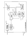
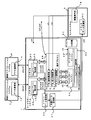
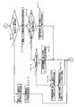
- a service providing quality control apparatus 500 maintains and manages definitions of activation states and operation orders of a plurality of business application system groups, and converts each element workflow part of a workflow to be controlled into a workflow. Collects and manages the descriptions of distributed element workflow parts in an environment where multiple workflow management systems that implement engines are managed and executed independently and distributed.
- An agreed service level information storage unit 501 for storing agreed service level information indicating service provision conditions of the entire workflow, defined as a state vector value, and an element workflow part that can be measured and calculated only by statistical processing, or the element workflow part
- a measurement statistic data calculation unit 502 for calculating a measurement statistic related to a service called from the system, sampling from the measurement statistic at a predetermined sampling period, and a current state vector value and a specified period of the measurement statistic immediately before the sampling time Based on the state observation unit 503 that calculates the history state vector value of the measurement statistic at the previous sampling time, and the state vector component that is synonymous with the target state vector value, based on the current state vector value and history state vector value of the measurement statistic State estimation vector values
- a simulation processing unit 504 that estimates after compensation at
- the control deviation is calculated by sequentially comparing the target state vector values to be determined, and a determination unit 506 for determining whether or not the control operation is necessary.
- the policy description management unit 505 After virtually changing the execution environment of the description of the entire workflow based on the policy description managed by the simulation, the simulation processing unit 504 and the determination unit 505 are re-executed, and the control deviation is less than or equal to a predetermined value up to a predetermined number of times.
- the adjustment unit 507 that adjusts the evaluation condition of the execution environment until it becomes the result of the adjustment of the evaluation condition by the adjustment unit 506 is no longer controlled
- a determination unit 508 that determines a change in the execution environment when the operation is not determined to be necessary;
- the service providing quality control apparatus 500 is connected to a plurality of workflow processing apparatuses 600 including a wf definition 602 for storing a description of an element workflow part and a workflow engine 601 for executing the element workflow part. Configure the provided quality control system.
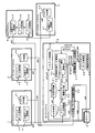
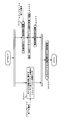
- FIG. 3 shows an example of an environment to which the service providing quality control apparatus according to the present embodiment is applied.
- the service providing quality control apparatus according to the present embodiment is applied to a case where a plurality of sub-networks including the Internet are connected by a router or the like under a set of management policies and security policies of the sub-networks. It is a general network environment that constitutes a network.
- the subnetwork 101 is connected to the subnetwork 102 and the subnetwork 103 via the router 106.
- the subnetwork 102 is connected to the subnetwork 105 via a router 108. Further, the subnetwork 105 is connected to the subnetwork 104 via the router 107.
- the sub-networks 101 to 105 may constitute the Internet, or may be local networks managed by companies or organizations.
- routers 106 to 108 are based on a unique policy, and may have a function as a firewall when connecting the Internet and a local network.
- the business application systems 7 to 12 are connected to any of the sub-networks 101 to 105.
- the workflow systems 1 to 3 that perform workflow processing by connecting the business application systems 7 to 12 and the proxy system 4 that performs various controls and the like on the configuration of the network are similar to any of the sub-networks 101 to 105.
- the monitor system 5 that provides the main functions of the service providing quality control apparatus based on the agreed service level is also connected to one of the sub-networks 101 to 105.
- the subnetwork 103 in which the business application systems 9 and 10 and the workflow system 2 are connected to the subnetwork 103 is arranged in one organization or department.
- the sub-network 104 to which the business application systems 11 and 12 and the Proxy system 4 are connected and the sub-network 5 to which the workflow system 3 is connected are arranged in one department. Assuming that
- the subnetwork 102 is an external network such as the Internet, and the monitor system 5 that provides a common function is connected to the subnetwork 102.
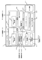
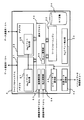
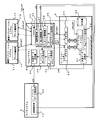
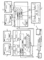
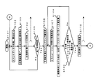
- FIG. 4 shows a configuration of the service providing quality control apparatus according to the present embodiment.
- the service providing quality control apparatus includes a plurality of workflow systems 1 and 2 based on a distributed workflow management method, a workflow system 3 arranged in an original implementation, a proxy system 4 that mediates the workflow system 3 to a distributed workflow management method, After collecting various event information from the workflow systems 1, 2 and the Proxy system 4, it has a management console 81 for organizing, integrating and storing, and an associated repository 6. Note that a plurality of uniquely implemented workflow systems 3 may be provided, and these may be intermediated by the Proxy system 4 together.
- the workflow system 1 communicates with a plurality of business application systems 7 and 8.
- the workflow system 2 communicates with a plurality of business application systems 9 and 10.
- the workflow system 3 communicates with a plurality of business application systems 11 and 12 via the Proxy system 4.
- the business application systems 7 to 12 have data communication units 13 to 18, respectively.
- the workflow system 1 includes an adapter 19 for communicating with the data communication unit 13 and a separate adapter 20 for communicating with the data communication unit 14.
- these adapters handle communication protocol differences and operations when necessary communication is performed with the business application systems 7 and 8.
- the operation proxy 48 acts as one of the control units when performing control.
- the functions of the adapters 19 and 20 may be included in the operation proxy 48 and mounted.
- the workflow system 2 includes an adapter 21 for communicating with the data communication unit 15 and a separate adapter 22 for communicating with the data communication unit 16.
- these adapters handle communication protocol differences and operations when necessary communication is performed with the business application systems 9 and 10.
- the workflow engine 32 communicates via the adapters 21 and 22, the operation is performed through the operation proxy 49.
- the functions of the adapters 21 and 22 may be included in the operation proxy 49 and mounted.
- the workflow system 3 includes an adapter 23 for communicating with the data communication unit 17 and a separate adapter 24 for communicating with the data communication unit 18.
- These adapters handle differences in communication protocols and operations when performing necessary communication with the business application systems 11 and 12 as a result of the workflow engine 37 included in the workflow system 3 operating the operation order.
- workflow system 3 is an existing workflow engine that is uniquely implemented, communication between the data communication unit 17 and the adapter 23 and communication between the data communication unit 18 and the adapter 24 are performed in the Proxy system 4. This is performed via the proxy unit 35.
- Workflow systems 1 to 3 may be configured on one computer or may be distributed on a plurality of computers.
- the behavior of the workflow engines 29 and 29 ′ is defined by a workflow definition 31 included in the workflow system 1.
- the workflow engines 29 and 29 ' may be another program execution body implemented by a virtualization technique or a grid. Alternatively, a plurality of programs may be activated in one execution object image such as threads and program processes.
- the workflow engines 29 and 29 ' may execute the same workflow definition, or may share and execute a part of a workflow definition. The form depends on the workflow system 1.
- the activation and stop of the workflow engines 29 and 29 ′ are controlled by the environment of the workflow system 1.
- the workflow definition 31 includes an event related to a processing request / processing response message from another workflow system 2 and the workflow system 3 communicated via the proxy system 4, and a plurality of business application systems 7 and 8.
- an event related to a process request / process response message generated as a result of communication occurs, it defines what state the workflow engine 29, 29 ′ is in and what process request / process response message is issued.
- the workflow definition 31 describes only the behaviors performed by the workflow engines 29 and 29 ', and starts with standardized forms such as WS-BPEL (Web Service Business Process Execution Language) and WDSL (Web Service Definition Language). It is described by the process and service description to be performed.
- the behavior of the workflow engine 32 is defined by a workflow definition 34 included in the workflow system 2.
- events related to processing request / processing response messages from other workflow systems 1 and the workflow system 3 communicated via the proxy system 4 and communication with a plurality of business application systems 9 and 10 are distributed.
- an event related to a processing request / processing response message that occurs as a result occurs, what kind of next state the workflow engine 32 is in and what processing request / processing response message is issued is defined.
- the workflow definition 34 describes only the behavior of the workflow engine 32, and is described by a process, service description, etc. including WS-BPEL and WSDL which are standardized formats.
- the behavior of the workflow engine 37 is defined by a workflow definition 39 included in the workflow system 3.
- processing requests communicated from other workflow systems 1 and 2 through the Proxy system 4 events related to processing response messages, and processing requests and processing communicated from the business application systems 11 and 12 through the Proxy system 4
- an event related to a response message occurs, it defines what kind of next state the workflow engine 37 enters and what kind of processing request / processing response message is issued.
- the workflow system 3 is an existing workflow engine that is uniquely implemented, the workflow definition 39 is not always described in WS-BPEL and WSDL, which are standardized formats. In that case, a workflow definition / service definition acquisition unit 59 described later converts them into standardized formats such as WS-BPEL and WSDL.
- Events relating to processing request / processing response messages generated in the workflow system 1 are detected by a plurality of event extraction units existing in the workflow system 1. All communications between the data communication unit 13 and the adapter 19 are detected by the Msg event extraction unit 25 installed in the adapter 19. Similarly, all communication between the data communication unit 14 and the adapter 20 is detected by the Msg event extraction unit 26 installed in the adapter 20. The behavior of the workflow engines 29 and 29 ′ is detected by the Eng event extraction unit 30.
- the event information extracted by the Msg event extraction units 25 and 26 and the Eng event extraction unit 30 is temporarily stored in the event data holding unit 40 in the workflow system 1 and appropriately sent to the monitoring system 5 by the common data transmission unit 41. Transferred.
- Events related to processing request / processing response messages generated in the workflow system 2 are detected by a plurality of event extraction units existing in the workflow system 2. All communications between the data communication unit 15 and the adapter 21 are detected by the Msg event extraction unit 27 installed in the adapter 21. Similarly, all communications between the data communication unit 16 and the adapter 22 are detected by the Msg event extraction unit 28 installed in the adapter 22. The behavior of the workflow engine 32 is detected by the Eng event extraction unit 33.
- the event information extracted by the Msg event extraction units 27 and 28 and the Eng event extraction unit 33 is temporarily stored in the event data holding unit 42 in the workflow system 2 and appropriately sent to the monitor system 5 by the common data transmission unit 43. Transferred.
- Collection of events related to processing request / processing response messages that occur in the workflow system 3 is an existing workflow engine that is uniquely implemented. Therefore, events related to processing requests / processing response messages that occur in the workflow systems 1 and 2 have a processing method. Different. Since the communication between the data communication unit 17 and the adapter 23 is performed via the proxy unit 35, the event related to the generated processing request / processing response message is connected to the proxy unit 35 in the Proxy system 4. It is detected by the event extraction unit 36. An event related to a processing request / processing response message that occurs in communication between the data communication unit 18 and the adapter 24 is also detected by the Prx event extraction unit 36.
- the event information extracted by the event detection unit 36 is temporarily stored in the event data holding unit 45 in the Proxy system 4.
- the behavior of the workflow engine 37 is detected by the Eng event extraction unit 38 arranged in the workflow system 3. Thereafter, the data related to the event is appropriately transmitted to the Proxy system 4 using the common data transmission unit 47 arranged in the workflow system 3.
- the Proxy system 4 collects data related to the event using its own common data receiving unit 46 and temporarily stores it in the event data holding unit 45 in the Proxy system 4.
- All data related to the event temporarily stored in the event data storage unit 45 is appropriately transferred to the monitor system 5 by the common data transmission unit 44.
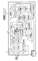
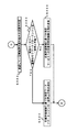
- the monitor system 5 includes a workflow definition / service definition acquisition unit 59, a workflow definition synthesis unit 60, a synthesis workflow definition 61, an event data reception unit 62, an event data association unit 63, and a measurement control amount management unit. 64, event / statistics storage data database (DB) 65, metadata management unit 66, measurement statistics data calculation unit 67, performance data management unit 68, activation control unit 69, state observation unit 70, simulation processing unit 71 with compensation function , Target state vector value management unit 72, detection unit 73, evaluation condition adjustment unit 74, policy description management unit 75, adjustment operation unit 76, measurement state vector value processing unit 77, long-term compensation detection unit 78, buffer unit 79, and execution conditions A designation unit 80 is included.
- DB event / statistics storage data database
- the workflow definition / service definition acquisition unit 59 receives the workflow definitions 31, 34, and 39 and performs partial conversion.
- the workflow definition / service definition acquisition unit 59 can access the repository 6 placed outside.
- the workflow definition synthesis unit 60 synthesizes an integrated workflow definition from all the workflow definitions obtained by the workflow definition / service definition acquisition unit 59.
- the combined workflow definition 61 stores and manages the combined workflow definition.
- the event data receiving unit 62 receives all data related to events from the workflow systems 1 and 2 and the Proxy system 4.
- the event / statistics storage DB 65 refers to the combined workflow definition 61 that stores and manages the integrated and combined workflow definitions, and organizes, holds, and associates all event data received by the event data receiving unit 62.
- the measurement control amount management unit 64 manages the event / statistics storage DB 65.
- the event data correlation unit 63 performs the actual processing of the previous correlation.
- the metadata management unit 66 uses only statistical processing to estimate the number of messages distributed per unit time, the number of messages rejected due to communication failure, and the number of integrated / synthetic workflow processes.
- the combined workflow definition 61 and the workflow definition integrated and synthesized from the repository 6 and its element description are extracted. Manage on memory.
- the measurement statistic data calculation unit 67 extracts related event data from all the event data stored in the event / statistics storage DB 65, and integrates and synthesizes the workflow definition managed on the metadata management unit 66. And a measurement statistic group are calculated with reference to the element description.
- the performance data management unit 68 calculates the measurement statistic group and then manages the calculation result on the memory in order to process the calculation result at high speed in subsequent evaluation / calculation.
- the measurement statistic data calculation unit 67 corresponds to the measurement statistic data calculation unit 502 in the configuration shown in FIG.
- the activation control unit 69 is specified from the management console 81 and is referred to when operating the service providing quality control apparatus 2.
- the execution condition specifying unit 80 manages various parameter value groups, and measurement statistics. A state is estimated by performing a simulation based on the group, and in order to perform control based on the simulation, a sampling period is designated, and a simulation processing unit 71 with a compensation function, which will be described later, is started.
- the state observation unit 70 calculates a vector value group consisting of measurement statistic groups measured immediately before and one sampling period before the control sampling period, for state estimation at an arbitrary time point regarding the agreed service level to be controlled. In association with the information obtained from the metadata management unit 66, it is obtained from the performance data management unit 68 and maintained.
- the state observation unit 70 corresponds to the state observation unit 503 in the configuration shown in FIG.
- the target state vector value management unit 72 manages the target value group and vector value group related to the agreed service level to be realized by the service providing quality control device.
- the target state value vector value management unit 72 corresponds to the agreed service level storage unit 501 in the configuration shown in FIG.
- the simulation processing unit with compensation function 71 designates a vector value group consisting of a group of measurement statistics and an operation amount to be given to various control unit units to be described later, and then estimates and evaluates a state regarding an agreed service level at an arbitrary time point based on those. I do.
- the simulation processing unit with compensation function 71 corresponds to the simulation processing unit 504 in the configuration shown in FIG.
- the detecting unit 73 is a vector of a group of vector values for a state related to the agreed service level at an arbitrary time estimated and evaluated by the simulation processing unit 71 with a compensation function and a vector of a target value group related to the agreed service level managed by the target state vector managing unit 72 The control deviation is obtained by comparing with the value group.
- the detection unit 73 corresponds to the determination unit 506 in the configuration illustrated in FIG.
- the evaluation condition adjusting unit 74 temporarily determines the amount of operation to be given to the various control device units as needed.
- the simulation processing unit with compensation function 71 is used for estimation / evaluation up to the allowable designated number of times, and adjustments are made on the control measures so that the vector value group of the target value group regarding the agreed service level can be satisfied.
- the evaluation condition adjustment unit 74 corresponds to the adjustment unit 507 in the configuration shown in FIG.
- the policy description management unit 75 manages policies and the like to be referred to when the evaluation condition adjustment unit 74 temporarily determines the operation amount.
- the policy description management unit 75 corresponds to the policy description management unit 505 in the configuration shown in FIG.
- the adjustment operation unit 76 is a level at which the control deviation calculated by the detection unit 73 satisfies the vector value group of the target value group related to the agreed service level (hereinafter, agreed service level) determined for each of the plurality of service users, or the evaluation condition After the adjustment unit 74 adjusts and determines the operation amount to be given to the various control device units, the actual operation amount is given to the various control device units when the level satisfies the vector value group of the target value group related to the agreed service level. Instruct.
- the adjustment operation unit 76 corresponds to the determination unit 508 in the configuration illustrated in FIG.
- the buffer unit 79 holds a vector value group regarding a state related to the agreed service level at the designated time point estimated and evaluated by the simulation processing unit with compensation function 71 when the adjustment operation unit 76 instructs the actual operation amount.
- the measurement state vector value processing unit 77 can correctly maintain a fixed parameter value group that is referred to when the simulation processing unit with compensation function 71 estimates and evaluates a vector value group regarding a state related to the agreed service level at a specified time.
- the measured vector value group corresponding to the vector value group for the state related to the agreed service level estimated / evaluated by the simulation processing unit with compensation function 71 is traced back to the past, and all of the event / statistic storage DB 65 stored in the event / statistic storage DB 65 Calculate and manage from event data.
- the long-term compensation detection unit 78 is an estimated vector value group corresponding to a vector value group for a state related to the agreed service level managed by the measurement state vector value processing unit 77, and after estimation / evaluation by the simulation processing unit 71 with a compensation function.
- the policy description management unit 75 manages the vector value group for the states related to the agreed service levels at a plurality of time points held in the buffer unit 79, and the evaluation condition adjustment unit 74 temporarily determines the operation amount. Update and maintain the policy to be referenced.
- the vector value group for the state relating to the agreed service level is usually defined in units that are synthesized and defined by the workflow synthesis unit 60 from all workflow definitions such as the workflow definitions 31, 34, 39, and managed as the synthesized workflow definition 61. Will be. Therefore, the workflow definition 31 level workflow is partially different, and therefore when there are a plurality of service users, a plurality of vector value groups are provided.
- the adjustment operation unit 76 instructs the actual operation amount to various control device units, a plurality of control operations may be performed.
- a plurality of control operations may be performed.
- the workflow system 1 there is another workflow engine 29 ′ equivalent to the workflow engine 29, and therefore, additional activation and stop of the workflow engine 29 ′ may be controlled according to the processing load status. .
- the operation proxy 48 also acts as one of the control device units.
- the operation proxy 48 is provided with a forced rejection unit 50, an input suppression unit 51, and a queue management unit 52.
- the operation is performed through the operation proxy 48. Therefore, the distribution of communication messages is temporarily suppressed by the input suppression unit 51, included in the queue management unit 52, or the communication messages included in the queue management unit 52 are maintained within the agreed service level. It rejects using the forced rejection part 50.
- rectification can be realized by suppression / rejection or the like.
- the operation proxy 49 that also functions as the control device unit and the proxy unit 35 described later, in implementing the entire unit managed by the composite workflow definition 61, the bottleneck part is identified and rectification is promoted By doing so, the throughput of the entire unit can be improved.
- the operation proxy 49 of the workflow system 2 also functions as one of the control devices. For this reason, the operation proxy 49 is provided with a forced rejection unit 53, an input suppression unit 54, and a queue management unit 55.
- the Proxy system 4 that intervenes in communication between the adapter 23 in the workflow system 3 and the data communication unit 17 and communication between the adapter 24 in the workflow system 3 and the data communication unit 18.
- the proxy unit 35 also functions as one of the control unit units.
- the proxy unit 35 is provided with a forcible leg unit 56 corresponding to the forcible rejection unit 50, an input control unit 57 corresponding to the input control unit 51, and a queue management unit 58 corresponding to the queue management unit 52. It has been.
- the workflow elements constituting the workflow definition synthesized by the workflow definitions 31 and 34 and the workflow synthesis unit 60 are a direct product subset expressed by a tuple of the following formula (1).
- a context set that indicates under which workflow definition is activated is represented by the following symbol (D)
- a calling side service set is represented by the following symbol (E)
- a called side service set is represented by the following symbol (F).
- D a context set that indicates under which workflow definition is activated
- E a calling side service set
- F a called side service set
- G a natural number set of 0 or more indicated by the following symbol
- H a natural number set of 0 or more shown by the following symbol (H) means the number of call repetitions.
- the relationship of the following formula (2) is established between the calling side service set and the called side service set.
- Workflow definition is expressed by the following formula (3) using a set of workflow elements.
- name for specifying an arbitrary workflow definition is a one-to-one mapping given by the following equation (4).
- the processing request message m 1 is transmitted to the operation proxy 48 based on the workflow definition 31.
- the processing request message m1 may be formed by a Web service or the like, and is defined using XML (eXtensible Markup Language) or the like.
- the operation proxy 48 When the operation proxy 48 receives the processing request message m1, the operation proxy 48 temporarily suppresses it by the input suppression unit 51 and then includes the processing request message m1 in the queue management unit 52 or includes the processing request message m1 in the queue management unit 52 and then forcibly rejects Either 50 is rejected or a processing request message m2 having the same content as the processing request message m1 is transmitted to the adapter 19 according to the content of the processing request message m1.
- Whether the operation proxy 48 performs suppression, rejection, or transmission to the adapter 19 depends on the contents of the control message group related to the operation amount that the adjustment operation unit 76 instructs to the various control device units.
- the processing request message group to be suppressed the type of the processing response message group, the operation amount expressing the quantitative degree of suppression, and the like are specified from the adjustment operation unit 76 by the suppression message c52.
- an operation amount expressing a quantitative degree such as a processing request message group to be rejected, a type of processing response message group, a rejection rate, and the like is sent from the adjustment operation unit 76 by a control message c51. Specified.
- the processing request message group and the processing response message group for which nothing is specified by the control messages c51 and c52 are considered to specify that normal communication is performed without any particular operation.
- the control message group related to the operation amount instructed by the adjustment operation unit 76 to the various control units includes a control message c50 instructing the environment of the workflow system 1.
- the environment of the workflow system 1 Upon receiving the control message c50, the environment of the workflow system 1 evaluates the activation / deactivation of the workflow engines 29 and 29 ′, and controls to activate / deactivate the workflow engine 29 and control the processing contents as necessary. In addition to transmitting the command c53, a control command 54 for starting and stopping the workflow engine 29 ′ and changing the processing content is also transmitted.
- the adapter 19 converts the processing request message m2 into a communication protocol and procedure that can be accepted by the business application system 7, and transmits it to the data communication unit 13 in the business application system 7 as a new processing request message m3.
- the data communication unit 13 receives the processing request message m3 and delivers it to the business application system 7. As a result, if necessary, a new processing response message m4 is generated and returned from the data communication unit 13 to the adapter 19.
- the adapter 19 converts the processing response message m4 into a predetermined communication protocol and procedure, and returns the processing response message m4 to the operation proxy 48 as the processing response message m5.
- the operation proxy 48 When the operation proxy 48 receives the processing response message m5, the operation proxy 48 temporarily suppresses it by the input suppression unit 51 and then includes the processing response message m5 in the queue management unit 52, or includes the processing response message m5 in the queue management unit 52 and then the forcible rejection unit 50, or the process response message m6 having the same content as the process response message m5 is returned to the workflow engine 29 or 29 ′ waiting for reception after the process request message m1 is transmitted. This is performed according to the content of the response message m5.
- the workflow engine 29 receives the processing response message m6, the next behavior is determined based on the workflow definition 31. For example, as a result, when communicating with the business application system 8, the processing request message m 7 is transmitted to the operation proxy 48 this time based on the workflow definition 31.
- the processing request message m7 may also be formed by a web service or the like and is defined using XML or the like.
- the operation proxy 48 When the operation proxy 48 receives the processing request message m7, the operation proxy 48 temporarily suppresses it by the input suppression unit 51 and then includes the processing request message m7 in the queue management unit 52 or includes it in the queue management unit 52 and then forcibly rejects Either 50 is rejected or the processing request message m8 having the same content as the processing request message m7 is transmitted to the adapter 20 according to the content of the processing request message m7.
- the adapter 20 converts the processing request message m8 into a communication protocol and procedure that can be accepted by the business application system 8, and transmits it as a new processing request message m9 to the data communication unit 14 in the business application system 8.
- the data communication unit 14 receives the processing request message m9 and delivers it to the business application system 8. As a result, if necessary, a new processing response message m10 is generated and returned from the data communication unit 14 to the adapter 20.
- the processing response message m10 is converted into a predetermined communication protocol and procedure, and returned to the operation proxy 48 as the processing response message m11.
- the operation proxy 48 When the operation proxy 48 receives the processing response message m11, the operation proxy 48 temporarily suppresses it by the input suppression unit 51 and then includes the processing response message m11 in the queue management unit 52 or includes the processing response message m11 in the queue management unit 52 and then the forcible rejection unit 50, or the processing response message m12 having the same content as the processing response message m11 is returned to the workflow engine 29 that is in a reception waiting state after the processing request message m7 is transmitted. Perform according to the contents of m11.
- the workflow engine 29 determines the next behavior based on the workflow definition 31, but may communicate with another workflow system 2.
- the processing request message m86 is transmitted to the operation proxy 48 based on the workflow definition 31 with the workflow system 2 as the destination.
- the processing request message m86 may also be formed by a Web service or the like, and is defined using XML or the like.
- the operation proxy 48 When the operation proxy 48 receives the processing request message m86, the operation proxy 48 temporarily suppresses it by the input suppression unit 51 and then includes the processing request message m86 in the queue management unit 52 or includes the processing request message m86 in the queue management unit 52 and then forcibly rejects 50 is rejected or sent to the workflow system 2 as a processing request message m25 having the same content as the processing request message m86, depending on the content of the processing request message m86.
- the workflow system 2 In response to the processing request message m25, the workflow system 2 transmits a processing response message m26 and sends it to the operation proxy 48.
- the operation proxy 48 When the operation proxy 48 receives the processing response message m26, the operation proxy 48 temporarily suppresses the input by the input suppression unit 51 and then includes the processing response message m26 in the queue management unit 52 or includes the processing response message m26 in the queue management unit 52. 50, or the processing response message m87 having the same content as the processing response message m26 is returned to the workflow engine 29 that is in a reception waiting state after the processing request message m86 is transmitted. This is performed according to the content of the message m26.
- Events related to processing request / processing response messages generated in the workflow system 1 are extracted by an event extraction unit existing in the workflow system 1.
- the adapter 19 is provided with an Msg event extraction unit 25.
- the Msg event extraction unit 25 detects this when the adapter 19 receives the processing request message m2, and records it as an event m17 related to the message. Further, the Msg event extraction unit 25 detects this when the adapter 19 converts the processing request message m2 into a communication protocol and procedure that can be accepted by the business application system 7, and transmits it as the processing request message m3. Record as event m18.
- the Msg event extraction unit 25 detects this when the adapter 19 receives the processing response message m4 from the data communication unit 13, and records it as an event m19 related to the message.
- the Msg event extraction unit 25 detects this when the adapter 19 converts the processing response message m4 and transmits it as the processing response message m5 to the operation proxy 48, and records it as an event m20 related to the message.
- the adapter 20 is equipped with an Msg event extraction unit 26.
- the Msg event extraction unit 26 detects the processing request message m8 in the same manner as the Msg event extraction unit 25, and records it as an event m21 related to the message. Further, the processing request message m9 is detected and recorded as an event m22 related to the message. Further, the processing response message m10 is detected and recorded as an event m23 related to the message. Further, the processing response message m11 is detected and recorded as an event m24 related to the message.
- the behavior of the workflow engines 29 and 29 ′ is detected by the Eng event extraction unit 30.
- the Eng event extraction unit 30 handles all of a series of events related to messages generated from the workflow engines 29 and 29 ′ and received messages.
- the processing request message m1 delivered from the workflow engine 29 to the operation proxy 48 toward the adapter 19 is detected by the Eng event extraction unit 30 and recorded as an event m13 related to the message in the engine.
- the processing response message m6 returned from the adapter 19 to the workflow engine 29 via the operation proxy 48 is detected by the Eng event extracting unit 30 and recorded as an event m14 related to the message in the engine.
- processing request message m7 delivered to the adapter 20 from the workflow engine 29 to the operation proxy 48 is detected by the Eng event extraction unit 30 and recorded as an event m15 related to the message in the engine.
- processing response message m12 returned from the adapter 20 to the workflow engine 29 via the operation proxy 48 is detected by the Eng event extraction unit 30 and recorded as an event m16 related to the message in the engine.
- the processing request message m86 transmitted from the work engine 29 to the operation proxy 48 for communication with the workflow system 2 is detected by the Eng event extraction unit 30 and recorded as an event m27 related to the message in the engine. Further, the processing response message m87 corresponding to the processing response message c52 from the workflow engine 2 is also detected by the Eng event extracting unit 30 and recorded as an event m28 related to the message in the engine.
- Events m17 to m20 related to messages recorded by the Msg event extracting unit 25, events m21 to m24 related to messages recorded by the Msg event extracting unit 26, and events m13 to m15 related to messages in the engine detected by the Eng event extracting unit 30 , M27, and m28 are recorded in the event data holding unit 40 in the workflow system 1 and temporarily stored. Thereafter, the event data transfer message m29 is appropriately created in a predetermined format by the common data transmission unit 41 and transferred to the monitor system 5.
- the monitor system 5 has an event data receiving unit 62 that receives all data related to events, and receives an event data transfer message m29.
- the workflow engine 37 When the workflow engine 37 communicates with the business application system 11, it transmits a processing request message m 30 to the adapter 23 based on the workflow definition 39.
- the processing request message m30 may be formed by a Web service. In this case, the processing request message m30 is defined using XML or the like.
- the workflow system 3 is an existing workflow engine that is uniquely implemented, Communication with the adapter 23 and communication between the data communication unit 18 and the adapter 24 are realized via the proxy unit 35 in the Proxy system 4 and are not necessarily performed by a Web service or the like.
- the adapter 23 converts the processing request message m30 into a communication protocol and procedure that can be accepted by the business application system 11, and transmits it as a new processing request message m31 toward the data communication unit 17 in the business application system 11.
- the proxy unit 35 Since communication between the workflow system 3 and the business application system 11 is realized via the proxy unit 35 in the Proxy system 4, the proxy unit 35 once receives the processing request message m 31 and sends the processing request message to the data communication unit 17. By retransmitting as m32, transmission of the processing request message from the adapter 23 to the data communication unit 17 is realized.
- the proxy unit 35 When the proxy unit 35 receives the processing request message m31, the proxy unit 35 temporarily suppresses it by the input control unit 57 and then includes the processing request message m31 in the queue management unit 58 or includes it in the queue management unit 58 and then forcibly rejects Either the rejection using 56 or the re-transmission as the processing request message m32 is performed according to the content of the processing request message m31.
- the processing request message group to be suppressed the type of the processing response message group, the operation amount expressing the quantitative degree of suppression, and the like are specified from the adjustment operation unit 76 by the control message c56.
- an operation amount expressing a quantitative degree such as a processing request message group to be rejected, a type of a processing response message group, a rejection rate, etc. is sent from the adjustment operation unit 76 by a control message c55. It is specified.
- processing request message group and the processing response message group that are not specified by the control messages c55 and c56 are specified to perform normal communication without any particular operation.
- the data communication unit 17 When the data communication unit 17 receives the processing request message m32, the data communication unit 17 delivers it to the business application system 11. As a result, if necessary, a new processing response message m33 is generated, and a response is sent from the data communication unit 17 to the adapter 23.
- the proxy unit 35 since communication between the business application system 11 and the workflow system 3 is realized via the proxy unit 35 of the Proxy system 4, the proxy unit 35 once receives the processing response message m 33 and further processes the response to the adapter 23. By retransmitting the message m34, transmission of the processing response message from the data communication unit 17 to the adapter 23 is realized.
- the proxy unit 35 When the proxy unit 35 receives the processing response message m33, the proxy unit 35 temporarily suppresses it by the input suppression unit 57 and then includes the response message m33 in the queue management unit 58 or after including the response message m33 in the queue management unit 58. Either the rejection using the forcible rejection unit 56 or the re-transmission as the processing response message m34 is performed according to the content of the processing response message m33.
- the adapter 23 When the adapter 23 receives the processing response message m34 from the proxy unit 35, the adapter 23 converts it into a predefined communication protocol and procedure, and returns the processing response message m35 to the workflow engine 37.
- the workflow engine 37 determines the next behavior based on the workflow definition 39. As a result, when communicating with the business application system 12, the processing request message m 36 is transmitted to the adapter 24 based on the workflow definition 39.
- the adapter 24 converts the processing request message m36 into a communication protocol and procedure that can be accepted by the business application system 12, and transmits it to the data communication unit 18 in the business application system 12 as a new processing request message m37.
- the proxy unit 35 Since communication between the workflow system 3 and the business application system 11 is realized through the proxy unit 35 in the Proxy system 4, the proxy unit 35 once receives the processing request message m 37 and requests a new processing request to the data communication unit 18. Transmission of the processing request message from the adapter 24 to the data communication unit 18 is realized by retransmitting the message m38.
- the proxy unit 35 When the proxy unit 35 receives the processing request message m37, the proxy unit 35 temporarily suppresses it by the input control unit 57 and then includes the processing request message m37 in the queue management unit 58 or includes the processing request message m37 in the queue management unit 58. Depending on the content of the processing request message m37, either the forcibly rejecting unit 56 is used later or the processing request message m38 is retransmitted.
- the data communication unit 18 delivers the processing request message m38 to the business application system 12 when receiving the processing request message m38. As a result, if necessary, a new processing response message m39 is generated and sent from the data communication unit 18 to the adapter 24.
- the proxy unit 35 since communication between the business application system 12 and the workflow system 3 is realized via the proxy unit 35 in the Proxy system 4, the proxy unit 35 once receives the processing response message m 39 and further toward the adapter 24. By retransmitting the processing response message m40, transmission of the processing response message from the data communication unit 18 to the adapter 24 is realized.
- the proxy unit 35 When the proxy unit 35 receives the processing response message m39, the proxy unit 35 temporarily suppresses it by the input suppression unit 57 and then includes the processing response message m39 in the queue management unit 58 or includes the processing response message m39 in the queue management unit 58. Depending on the content of the processing response message m39, either the forcibly rejecting unit 56 is used later or the processing response message m40 is retransmitted.
- the processing response message m40 when the processing response message m40 is received from the proxy unit 35, the processing response message m40 is converted into a predetermined communication protocol and procedure and returned to the workflow engine 37 as the processing response message m41.
- the workflow engine 37 determines the next behavior based on the workflow definition 39, and may communicate with another workflow system 2 at that time. In this case, based on the workflow definition 39, the processing request message m88 is transmitted to the proxy unit 35 with the workflow system 2 as the destination.
- the processing request message m88 is not necessarily made by a Web service or the like, but is defined by an arbitrary expression.
- the proxy unit 35 When the proxy unit 35 receives the processing request message m88, the proxy unit 35 temporarily suppresses it by the input suppression unit 57 and then includes the processing request message m88 in the queue management unit 58 or includes the processing request message m88 in the queue management unit 58. Depending on the content of the processing request message m88, either the forcibly rejecting unit 56 is used later or the processing request message m48 is sent to the workflow system 2.
- the result of the processing request message m48 is returned to the proxy unit 35 as a processing response message m49.
- the proxy unit 35 When the proxy unit 35 receives the processing response message m49, the proxy unit 35 temporarily suppresses it by the input suppression unit 57 and then includes the processing response message m49 in the queue management unit 58 or includes the processing response message m49 in the queue management unit 58. Either the forcible rejection unit 56 is used for the later rejection or the processing response message m89 having the same content as the processing response message m49 is returned to the workflow engine 37 that is in a reception waiting state after the processing request message m88 is transmitted. Depending on the content of the processing response message m49.
- the detection of event groups related to processing request / processing response messages generated in the workflow system 3 is an existing workflow engine that is uniquely implemented. Therefore, a method different from the normal processing method (a method different from the workflow systems 1 and 2) may be used. Adopted.
- the event related to the generated processing request / processing response message is a Prx event linked to the proxy unit 35 in the Proxy system 4. It is detected by the extraction unit 36. An event related to a processing request / processing response message generated by communication between the data communication unit 18 and the adapter 24 is also detected by the Prx event extraction unit 36.
- the Prx event extraction unit 36 detects this when the adapter 23 transmits the processing request message m31, the proxy unit 35 receives it, and transmits it to the data communication unit 17 as the processing request message m32. Record as event m50. In addition, the Prx event extraction unit 36 detects this when the data communication unit 17 transmits the processing response message m33, the proxy unit 35 receives it, and transmits it to the adapter 23 as the processing response message m34. Recorded as an event m51 related to the message.
- the Prx event extraction unit 36 detects this when the adapter 24 transmits the processing request message m37, the proxy unit 35 receives it, and transmits it to the data communication unit 18 as the processing request message m38. And recorded as an event m52 related to the message.
- the Prx event extraction unit 36 detects this when the data communication unit 18 transmits the processing response message m39, the proxy unit 35 receives it, and transmits it to the adapter 24 as the processing response message m40. Recorded as an event m53 related to the message.
- the event information extracted by the Prx event extraction unit 36 is temporarily stored in the event data holding unit 45 in the Proxy system 4.
- the behavior of the workflow engine 37 is detected by the Eng event extraction unit 38 arranged in the workflow system 3.
- the processing request message m30 delivered to the adapter 23 is detected by the Eng event extracting unit 38 and recorded as an event m42 related to the message in the engine.
- the processing response message m35 delivered from the adapter 23 is detected by the Eng event extracting unit 38 and recorded as an event m43 related to the message in the engine.
- processing request message m36 delivered to the adapter 24 is detected by the Eng event extracting unit 38 and recorded as an event m44 related to the message in the engine.
- processing response message m41 delivered from the adapter 24 is detected by the Eng event detection unit 38 and recorded as an event m45 related to the message in the engine.
- the communication with another workflow system 2 is handled in the same manner, and the processing request message m88 transmitted to the workflow system 2 is detected by the Eng event extraction unit 38 and recorded as an event m46 related to the message in the engine.
- a processing response message m89 returned as a result of the processing request message m88 is also detected by the Eng event extracting unit 38 and recorded as an event m47 related to the message in the engine.
- an event data transfer message m54 is created in a predetermined format using the common data transmission unit 47 arranged in the workflow system 3, and the data relating to the event is appropriately transferred to the Proxy system 4.
- the Proxy system 4 receives the event data transfer message m54 related to the event by using its own common data receiving unit 46, and temporarily stores it in the event data holding unit 45 in the Proxy system 4.
- the event data transfer message m55 is created in a predetermined format by the common data transmission unit 44 and is appropriately transferred to the monitor system 5
- the monitor system 5 is provided with an event data receiving unit 62 that receives all data related to the event, and receives the event data transfer message m55.
- FIG. 11 shows a procedure for collecting workflow definitions that are uniquely held in a distributed workflow engine and generating an integrated / synthesized workflow definition, and processing the measured data for control purposes. The outline of the procedure is shown.
- FIG. 15 shows a control procedure of the service providing quality control apparatus according to the present embodiment. A procedure for processing the measured data and providing it for control purposes will be described with reference to FIGS. 11 and 15.
- the behavior of the workflow engines 29 and 29 ′ included in the workflow system 1 is defined by the workflow definition 31.
- the workflow definition 31 describes only the behavior of the workflow engines 29 and 29 ′, and is described by processes, service descriptions and the like including WS-BPEL and WSDL which are standardized formats.
- the behavior of the workflow engine 32 included in the workflow system 2 is defined by the workflow definition 34.
- the workflow definition 34 describes only the behavior of the workflow engine 32, and is described by processes, service descriptions, and the like including WS-BPEL and WSDL, which are standardized formats.
- the behavior of the workflow engine 37 included in the workflow system 3 is defined by a workflow definition 39.
- the workflow system 3 is an existing workflow engine that is uniquely implemented, the workflow definition 39 is not always described in WS-BPEL and WSDL, which are standardized formats.
- the workflow definition 31 is appropriately transferred to the workflow definition / service definition acquisition unit 59 in the monitor system 5 as the definition transfer message m60, the workflow definition 34 as the definition transfer message m61, and the workflow definition 39 as the definition transfer message m62.
- the workflow definition / service definition acquisition unit 59 determines the format of the definition transfer message. If the definition transfer message m62 in a format other than the standard format WS-BPEL or WSDL is received, it is standardized by the processing system provided in advance in the workflow definition / service definition acquisition unit 59. Retain and manage after equivalent conversion to WS-BPEL and WSDL.
- the service providing quality control apparatus targets only those that can be equivalently converted to WS-BPEL and WSDL standard formats.
- the workflow definition / service definition acquisition unit 59 corresponds to the workflow definitions 31, 34, and 39 by WS-BPEL and WSDL that are standardized formats obtained by receiving or converting the definition transfer messages m60, m61, and m52. All the information is stored inside. It is also possible to save in the repository 6 provided outside.
- a workflow synthesis unit 60 that newly synthesizes an integrated workflow definition based on information corresponding to the workflow definitions 31, 34, and 39 managed by the workflow definition / service definition acquisition unit 59 and other information. And a combined workflow definition 61 for storing and managing the combined workflow definition.
- the workflow synthesis unit 60 starts the workflow definition / service definition acquisition unit 59 as appropriate in order to obtain all the workflow definitions as elements.
- the workflow definition / service definition acquisition unit 59 makes an inquiry m85 to the repository 6 so that, in addition to the information corresponding to the workflow definitions 31, 34, and 39 already held inside, elements of the integrated / synthetic workflow All remaining workflow definition / service definition information m64 is obtained. In the case of a configuration without the repository 6, this inquiry is not performed.
- the workflow definition / service definition acquisition unit 59 converts all the workflow definition / service definition information into the workflow definition / service definition information m64 and information corresponding to the workflow definitions 31, 34, and 39 that are elements of the integrated / synthetic workflow.
- the definition information m65 is transferred to the workflow composition unit 60.
- the workflow synthesis unit 60 generates an integrated / synthesized workflow definition and is integrated / synthesized together with all the workflow definition / service definition information m65 that is the original information for generating the integrated / synthesized workflow definition.
- a set m66 of workflow definitions is passed to the composite workflow definition 61. Note that a known method as disclosed in Japanese Patent Application Laid-Open No. 2007-257513 can be applied to the procedure by which the workflow synthesis unit 60 generates an integrated and synthesized workflow definition.
- the combined workflow definition 61 includes information corresponding to the workflow definitions 31, 34, 39, information corresponding to all the workflow definition / service definition information m64, and the integrated / synthesized workflow definition. Yes.
- the event information extracted by the various event extraction units of the workflow system 1 is temporarily stored in the event data holding unit 40 in the workflow system 1 and appropriately monitored by the common data transmission unit 41 as the event data transfer message m29. Forwarded to In the monitor system 5, the event data receiving unit 62 that receives all data related to the event receives and processes the event data transfer message m29.
- the event information extracted by the various event extraction units of the workflow system 2 is temporarily stored in the event data holding unit 42 in the workflow system 2, and appropriately, as the event data transfer message m 63 by the common data transmission unit 43, the monitor system 5. Forwarded to In the monitor system 5, the event data receiving unit 62 receives and processes the event data transfer message m63.
- event information extracted by various event extraction units of the Proxy system 4 is temporarily stored in the event data holding unit 45 in the Proxy system 4.
- event information extracted by various event extraction units in the workflow system 3 linked with the Proxy system 4 is transmitted from the common data transmission unit 47 in the workflow system 3 to the Proxy system 4 as an event data transfer message m54.
- the proxy system 4 is provided with a common data receiving unit 46, which receives the event data transfer message m54. Thereafter, all event information described in the event data transfer message m54 is temporarily stored in the event data holding unit 45.
- All the data related to the event temporarily stored in the event data holding unit 45 is appropriately transferred to the monitor system 5 as the event data transfer message m55 by the common data transmission unit 44.
- the event data receiving unit 62 receives and processes the event data transfer message m55.
- the event data receiving unit 62 delivers all the data m67 related to the event to the event data associating unit 63.
- the event data associating unit 63 refers to the combined workflow definition 61 that stores and manages the integrated and combined workflow definition, and searches and refers to the service definition / process definition information m68 that is managed internally, and all the data related to the event. Which service / process message instance each m67 corresponds to is organized and related, and a message instance group m69 currently managed in the event / statistics storage DB 65 is searched and related. Thereafter, it is stored in the event / statistics storage DB 65 as a record of a new message instance m70.
- the event / statistics storage DB 65 not only holds and manages each of all the data m67 related to the event, but also statistics such as the message circulation volume per unit time for each service and the number of messages rejected due to communication failure.
- a measurement statistic group corresponding to various parameter groups from which facts can be derived and grasped only by processing is calculated, and then maintained and managed. These mean parameters that represent the behavior of the service.
- the service here means an interface in which the data communication unit 13 for calling the business application system 7 and the data communication unit 14 for calling the business application system 8 are virtualized and defined by a WSDL service description or the like. .
- a data communication unit 15 for calling the business application system 9 a data communication unit 16 for calling the business application system 10, and a data communication unit 18 for calling the business application system 11 are provided in a WSDL service description or the like.
- a virtualized interface is also equivalent to a service.
- the measurement statistic group corresponding to the various parameter groups for each service must be estimated using simulation, such as the number of integrated / synthetic workflow processes that have a complex structure consisting of several selected services. If it can not be calculated, it must be measurable. Furthermore, there is a case where it is determined depending on time factors.
- a vector value group that represents a parameter group related to the agreed service level which will be described later, is obtained from a determinant ⁇ (i, s) (t) with respect to time t through a non-linear mapping and is represented by the following symbol (I)
- a set of evaluation parameters related to a workflow having a scalar quantity in all the workflow definition set elements is defined as a determinant (Y) of the following formula (6).
- workflow definition of Expression (6) may be any of the workflow definitions synthesized and integrated by the workflow definitions 31 and 34 and the workflow synthesis unit 60.
- This preprocessing corresponds to step S101 in FIG.
- the metadata management unit 66 includes an integrated / synthesized workflow definition m 73, information corresponding to all the workflow definitions 31, 34, and 39 that are the original information for generating the workflow definition m 73, and all other workflows.
- Information of the definition / service definition information m64 is extracted from the composite workflow definition 61 and the repository 6 as a set of definition information m74, and managed on the memory.
- the metadata management unit 66 obtains the relationship between all integrated / synthesized workflow definitions m73 and terminal service definitions from the set of definition information m74. This is defined as the cumulative call frequency taking into account, for example, a While loop and conditional branching. The maximum number of While Loops is counted as a frequency, each conditional branch is counted as a single frequency, and the determinant corresponding to the integrated and synthesized workflow definition and the terminal service definition calculated by standardizing with the maximum frequency. It is expressed by Thereafter, this information is also managed on the memory.
- a measurement statistic data calculation unit 67 that calculates a measurement statistic group obtains a measurement statistic group for each service definition. If the integrated / synthesized workflow definition matches another workflow element, if necessary and possible, set the corresponding measurement statistics group for each element workflow definition and each integrated / synthesized workflow definition. Ask. For this reason, the measurement statistic data calculation unit 67 generates metadata for the integrated / synthesized workflow definition list m75 and all the workflow definition / service definitions m76 that are the original information for generating each of the lists m75. Obtained from the management unit 66 and managed on the memory.
- the measurement statistic data calculation unit 67 measures the measurement control amount for managing the event / statistics storage DB 65.
- a search request m71 is appropriately transmitted to the data management unit 64. Since the search request m71 depends on the calculation content, the search request m71 does not always have the same content.
- the measurement control amount data management unit 64 searches the event / statistic storage DB 65 and transmits the result to the measurement statistics data calculation unit 67. Thereby, the measurement statistic data calculation unit 67 obtains a list m72 of event data related to the calculation target. This corresponds to step S102 in FIG.
- the measurement statistic data calculation unit 67 refers to the integrated / synthesized workflow definition list m75 and all the workflow definitions / service definitions m76 that are the original information for generating each of the lists m75. Then, a parameter group calculated as a measurement statistic group is sequentially calculated. This corresponds to step S103 in FIG.
- the calculated measurement statistic group is stored in the measurement control amount data management unit 64 and the performance data management unit 68. This corresponds to step S104 in FIG. As shown in FIG. 15, the above processing is performed for the number of parameters that configure and define the measurement statistics group (step S105).
- the measurement statistic data calculation unit 67 performs the calculation from the parameter 1.
- the measurement statistic data calculation unit 67 sends a search request m71 to the measurement control amount data management unit 64 that manages the event / statistics storage DB 65.
- the measurement control amount data management unit 64 searches the event / statistics storage DB 65, and as a result, the measurement statistics amount data calculation unit 67 obtains a list m72 of event data related to the calculation target (step S102). Thereafter, the measurement statistic data calculation unit 67 calculates the current value of the parameter 1 (step S103).
- the measurement statistic data calculation unit 67 transmits an update request m77 including the calculation result to the measurement control amount data management unit 64. Thereby, the calculation result of the parameter 1 is stored together with the time information in the event / statistic storage DB 65 (step S104).
- the measurement statistic data calculation unit 67 has a performance data management unit 68 that manages the values on the memory.
- a management request m81 corresponding to the update request m77 including the calculation result is transmitted.
- the performance data management unit 68 manages the calculation result of the parameter 1 together with the time information (step S104).
- the measurement statistic data calculation unit 67 makes a search different from the search request m71 to the measurement control amount data management unit 64 that manages the event / statistics storage DB 65. A request m71 ′ is transmitted. As a result, the measurement control amount data management unit 64 searches the event / statistics storage DB 65, and as a result, the measurement statistics data calculation unit 67 obtains a list m72 'of event data related to the calculation target (step S102). Thereafter, the measurement statistic data calculation unit 67 calculates the current value of parameter 2 (step S103).
- the measurement statistic data calculation unit 67 transmits an update request m 78 including the calculation result to the measurement control amount data management unit 64. Thereby, the calculation result of the parameter 2 is stored in the event / statistics storage DB 65 together with the time information (step S104).
- the measurement statistic data calculation unit 67 calculates the value to the performance data management unit 68 that manages the value on the memory in order to process the calculation result at high speed in subsequent evaluation / calculation.
- a management request m82 corresponding to the update request m78 including the result is transmitted.
- the performance data management unit 68 manages the calculation result of the parameter 2 together with the time information (step S104).
- the measurement statistic data calculation unit 67 measures the measurement control amount data for managing the event / statistics storage DB 65.
- a new search request m71 obtained by changing a part of the search request m71 is transmitted to the management unit 64.
- the measurement control amount data management unit 64 searches the event / statistics storage DB 65, and as a result, the measurement statistic data calculation unit 67 obtains a list m72 of event data related to the calculation target (step S102). Thereafter, the measurement statistic data calculation unit 67 calculates various values of the parameter 1 (step S103).
- the measurement statistic data calculation unit 67 manages the update request m79 including the calculation result as the measurement control variable data management. To the unit 64. Thereby, the calculation result at the designated time of parameter 1 and the calculation result regarding the statistical processing are stored together with the time information in the event / statistic storage DB 65 (step S104).
- the calculation result at the designated time of parameter 1 and the calculation result related to statistical processing are processed at high speed in subsequent evaluation / calculation, so that the measurement statistic data calculation unit 67 performs performance data for managing values on the memory.
- a management request m83 corresponding to the update request m79 including the measurement statistic calculation result is transmitted to the management unit 68.
- the performance data management unit 68 manages the calculation result at the designated time of the parameter 1 and the calculation result related to the statistical processing together with the time (step S104).
- the measurement statistic data calculation unit 67 measures the measurement control amount that manages the event / statistics storage DB 65.
- a new search request m71 ′ obtained by changing a part of the search request m71 ′ is transmitted to the data management unit 64.
- the measurement control amount data management unit 64 searches the event / statistics storage DB 65, and as a result, the measurement statistic data calculation unit 67 obtains a list m72 'of event data related to the calculation target (step S102). Thereafter, the measurement statistic data calculation unit 67 calculates various values of the parameter 2 (step S103).
- the measurement statistic calculation unit 67 sends an update request m80 including the calculation result to the measurement control amount data management unit 64.
- the calculation result at the designated time of parameter 2 and the calculation result related to the statistical processing are stored together with the time information in the event / statistic storage DB 65 (step S104).
- the measurement statistic calculation unit 67 uses performance data for managing values on the memory.
- a management request m84 corresponding to the update request m80 including the calculation result is transmitted to the management unit 68.
- the performance data management unit 68 manages the calculation result at the designated time point of the parameter 2 and the calculation result regarding the statistical processing together with the time information (step S104).
- FIGS. 12 and 13 show an operation at the time of service quality control of the service quality control apparatus according to the present embodiment.
- 15 to 17 are flowcharts showing the control procedure.
- FIG. 18 is a flowchart illustrating a procedure for selecting operation candidates.
- 19 to 21 are flowcharts showing a procedure for carrying out control operation formulation.
- the state observation unit 70 When the state observation unit 70 receives the activation request c1 corresponding to the sampling cycle from the activation control unit 69, the current value and the accumulated value / average value regarding the plurality of parameter groups managed by the performance data management unit 68 on the memory. Etc. For example, the calculation result c4 of the current parameter 1, the cumulative value / average value c5 of the parameter 1 up to the current time, the calculation result c6 of the current parameter 2 and the cumulative value / average value c7 of the parameter 2 up to the current time. As described above, the parameter 1 and the parameter 2 have a property that allows the facts to be grasped only by statistical processing, and are parameter groups that mean service behavior.
- the state observing unit 70 lists the integrated / synthesized workflow definition list c2 managed on the memory by the metadata management unit 66 and all the workflows that are the original information for generating each of the lists c2.
- a definition information set c3 of the definition / service definition is obtained.
- parameter 1 and parameter 2 are aggregated for each service definition, and a vector value having element 1 as parameter 1 and parameter 2 is defined.
- a matrix expressed by the above formula (5) in which the vector values of the service group are ranked for all services is defined.
- a matrix indicating the state of the sampled time is held as a state matrix c8 of the sampling time.
- a state matrix c9 that is one sampling period earlier than the sampling time of the state matrix c8 and is equivalent to the matrix c8 that is calculated and held and managed is continuously held. This corresponds to step S106 in FIG.
- the state observation unit 70 defines the “state matrix c8 at the sampling time”, the “state matrix c9 one cycle before the sampling time”, and “the element workflow that calls all services, and the workflow definitions 31, 34, 39 shows the relationship between the service group and the element workflow group corresponding to 39, definition information set c10 corresponding to definition information set c3, and “integrated / synthesized workflow definition list c2”.
- the workflow definition set c11 as an argument / input, an invocation command c12 for activating the compensation function-equipped simulation processing unit 71 is transmitted.
- the simulation processing unit 71 with a compensation function is configured for each set c11 of workflow definitions integrated and synthesized based on a time-corrected equivalent matrix derived from the state matrix c8 at the sampling time and the state matrix c9 one period before the sampling time.
- the vector value group c14 which means the parameter group regarding the agreed service level is estimated and calculated. Note that a plurality of values are calculated in a form in which the simulation time is compensated.
- FIG. 14 shows the configuration of the simulation processing unit 71 with a compensation function.
- the simulation processing unit with compensation function 71 has one or more behavior functions inside.
- a plurality of behavior functions 120 having the same image are generated according to the simulation processing time.
- the behavior function 120 also performs start-up management such as a procedure for estimation associated with feedforward control and management of the number of times of simulation execution including calculation time delay compensation associated with simulation.
- the behavior function 120 is composed of three parts. The first is related to the list c11 of workflow definitions that are defined, integrated, and synthesized for the element workflow in the set of definition information c10, and the sequential machine simulation units 121 and 121 that simulate the sequential mechanical behavior of the workflow. 'Is.
- the second is a service characteristic function calculation unit 124 that expresses the behavior characteristics of all terminal service groups in the definition information set c10 and simulates the behavior under specified conditions.
- the third is a processing system 130 provided in the behavior function 120 in order for the simulation processing unit 71 with a compensation function to calculate a vector value group based on a parameter relating to the agreed service level to be returned to the outside after the simulation is performed.
- the service characteristic function calculation unit 124 handles an end-of-line service group that has observability and linearity by defining equivalent behavior, whereas the sequential machine simulation units 121 and 121 ′ perform sequential mechanical functions of the workflow. The behavior is simulated and only the operation timing is treated equivalently.
- a plurality of sequential machine simulation units 121 and 121 ′ are generated according to the number of definitions of the integrated / synthesized workflow definition set c ⁇ b> 11, and are executed independently except for waiting restrictions on processing. In contrast, only one service characteristic function calculation unit 124 is generated.
- the service characteristic function calculation unit 124 holds pre-measurement characteristic data regarding the behavior of all end service groups.
- the characteristic data regarding the behavior of the business application system 7 is expressed by the business application system behavior characteristic constant 125. This may be a simple scalar quantity, or a vector quantity or tensor quantity that is a combination of predetermined parameter values.
- the characteristic data regarding the behavior of the business application system 8 is expressed by the business application system behavior characteristic constant 126.
- the characteristic data regarding the behavior of the business application system 9 is expressed by a business application system behavior characteristic constant 127.
- the characteristic data regarding the behavior of the business application system 10 is expressed by a business application system behavior characteristic constant 128.
- the service characteristic function calculation unit 124 when the parameter group of the measurement statistics group at a certain point is given to the service characteristic function calculation unit 124, another parameter group to be evaluated is calculated based on the business application system behavior characteristic constants 125 to 128. For example, a parameter group such as a service request arrival rate required for each service is given to the service characteristic function calculation unit 124 to calculate a parameter group such as an average response time.
- the service characteristic function calculation unit 124 is a function for calculating an equivalent behavior. For this reason, even if the service has a complicated configuration, it can be handled as a model. However, only those that have linearity and the property that can be observed and equivalent behavior can be defined. For example, the business application system 7 and the business application system 10 have some relationship that is not even defined as a table. Depending on the variation of the parameter group of the business application system 7, some variation is caused in the business application system 10 as a causal relationship. When seen, it becomes possible to handle its behavioral characteristics and the like.
- business application system behavior characteristic constants 125 to 128 can be held fixedly, they are normally set at the time of startup, and are held as appropriate constants on the memory during startup of the simulation processing unit with compensation function 71.
- Each of the sequential machine simulation units 121 and 121 ′ is generated based on each integrated and synthesized workflow definition. They internally have element workflow model groups 122 and 123 called by the integrated / synthesized workflow definition.
- the element workflow model groups 122 and 123 are defined by equivalently converting the workflow definitions 31, 34, and 39 that are information described in WS-BPEL.
- the description method of the element workflow model groups 122 and 123 is defined by a Petri net, a sequential machine, or the like.
- the Petri net is used.
- the element workflow models 122 and 123 may be realized by other methods such as a sequential machine.
- the sequential machine simulation unit 121 When the processing in the simulation processing unit with compensation function 71 is started, the sequential machine simulation unit 121 is activated, and for each of the set c11 of workflow definitions integrated and synthesized with respect to the element workflow model group 122 positioned at the head. Fire a Petri net token according to the expected service request arrival rate. Multiple tokens are generated.
- the sequential machine simulation unit 121 executes the action at that time.
- the service characteristic function calculation unit 124 is set based on a time-compensated equivalent matrix derived from the state matrix c9 one period before the sampling time and the state matrix c8 of the sampling time. call. Thereafter, the service characteristic function calculation unit 124 calculates another parameter group to be evaluated, and sends the parameter group c80 to the processing system 130 together with the designation of the token. Thereafter, the service characteristic function calculation unit 124 returns the processing to the sequential machine simulation unit 121.
- the parameter group c80 corresponds to the average response time for the service request arrival rate required for each service.
- the processing system 130 receives the calculated parameter group c80 together with the token designation. Thereafter, a plurality of generated parameter groups c80 are collected for each token, and calculation processing such as summation is performed for each element of the parameter group c80 to obtain a calculation parameter group c81.
- This calculation process uses different mathematical formulas depending on the contents of the parameters. By repeating the above series of procedures, it is possible to simulate the execution contents for one integrated and synthesized workflow definition process.
- the processing system 130 Since a plurality of tokens are generated, by performing statistical processing on the calculation parameter group c81, the processing system 130 generates a vector value group c14 that represents a parameter group related to the agreed service level for each set c11 of the integrated and synthesized workflow definitions. It can be calculated.
- the simulation processing unit with compensation function 71 Upon receiving this result, the simulation processing unit with compensation function 71 returns the vector value group c14, which means a group of parameters related to the agreed service level, to the outside after the simulation is performed.
- the behavior function 120 in the simulation processing unit 71 with a compensation function performs a procedure for calculation time delay compensation accompanying simulation and estimation accompanying feedforward.
- the value of the vector value group c14 that means a parameter group related to the agreed service level for each set c11 of the integrated / synthesized workflow definition also changes in accordance with the compensation condition referred to at the time of compensation.
- the parameter group related to the agreed service level is defined by a determinant having the same type as the above equation (6), but includes calculation time delay compensation accompanying simulation and estimation accompanying feedforward. Computation time delay compensation associated with the simulation, estimation method associated with feedforward, and behavior definition with respect to the time axis will be described later with reference to FIG.
- the simulation processing unit with compensation function 71 repeatedly performs p times (p is an integer of 1 or more) about steps S107 and S108 in FIG. 15 (step S109).
- p is an integer of 1 or more
- the estimated total number of calculations by the simulation processing unit with compensation function 71 is executed at maximum 2p times in one sampling period of control, and the first half of them is continuously performed at this stage. carry out.
- a buffer unit stores a vector value group c14 ′ having the same value as “a vector value group c14 that means a parameter group related to the agreed service level for each set c11 of integrated and synthesized workflow definitions”. It is output together with the time to 79 and managed / held. This corresponds to step S110 in FIG.
- the simulation processing unit with compensation function 71 uses the vector value group c14 as an argument.
- a restart command c15 for activating the detection unit 73 is transmitted to the detection unit 73.
- the detection unit 73 reads in advance the “vector value group c16 of the target value group related to the agreed service level” decided for each of a plurality of service users managed by the target state vector value management unit 72 in the initialization process after startup. It is out.
- the vector value group c16 of the target value group related to the agreed service level is mainly composed of three parts.
- the first is the vector value group itself of the target value group related to the agreed service level, and the second is that the target state vector value management unit 72 registers the vector group c16 of the target value group related to the agreed service level in the management console 81.
- the third information is information corresponding to relative information between parameter value groups constituting the vector value group of the target value group related to the agreed service level.
- evaluation values are specified for all elements of the evaluation parameter set for all workflows with a scalar quantity, and are regarded as constant with no time variation. This is defined as a target state vector value whose control target is SLA information.
- the detection unit 73 calculates eigenvalues for priority evaluation in advance.
- the detection unit 73 upon receiving the restart command c15 from the simulation processing unit 71 with compensation function, receives a priority evaluation eigenvalue (expression (9)) calculated from the vector value group c16 of the target value group related to the agreed service level. )) And the vector value group c14 (formula (6)), a new control deviation matrix is estimated and calculated.
- control deviation is expressed as a deviation width with respect to the target value expressed in Expression (9).
- no special evaluation function is used in calculating the deviation.
- various parameter definitions are devised so that simple differences can be defined.
- the control condition is determined based on the control deviation calculated by equation (12). This corresponds to step S111 in FIG. In this procedure, in order to evaluate whether or not the vector value group c14 is sufficient and exceeds all of the vector value group c16 of the target value group, it is performed for all the vector value group components (step S112). ).
- the vector value group c14 is sufficient, there are cases where it does not exceed all the vector value groups c16 of the target value group.
- the relative information between the parameter value groups constituting the vector value group c16 of the target value group related to the agreed service level may be used to determine whether or not to have a significant influence.
- the detection unit 73 determines the evaluation condition adjustment unit 74 when the control deviation is not satisfactory as a result of determining the control condition, or when the control condition is not changed even if the control deviation is satisfied in advance. It will be started (step S113 / No). In FIG. 16, [No] is obtained when the control deviation is not satisfactory. Furthermore, if the control condition is not changed even if the control deviation is satisfied in advance, [YES ⁇ control condition change flag not set ⁇ ] is set (step S113 / Yes).
- the detection unit 73 transmits an activation command c17.
- necessary information such as the eigenvalue of the priority evaluation given by the following equation (13) and the compensation estimated value of the simulation time of the control deviation matrix given by the above equation (12) is passed as an argument.
- the simulation processing unit with compensation function 71 Prior to the transmission of the start command c17, it is determined whether or not the simulation processing unit with compensation function 71 has been performed a predetermined number of times or more within one sampling period of control (step S114).
- step S114 / Yes if p has been performed for the specified number of times or more (step S114 / Yes), it is regarded as an operation failure. As a result, as described in step S115 in FIG. 16, the control condition is not changed, and an alarm c91 for performing step S116 in FIG. 16 is transmitted.
- the simulation processing unit with compensation function 71 has not been executed more than the specified number of times (step S114 / No), and when the evaluation condition adjustment unit 74 is activated in response to the activation command c17, the control operation is started. To do.
- the evaluation condition adjustment unit 74 performs processing corresponding to step S117 in FIG. 16 based on the procedure shown in FIG.
- step S117 The process in step S117 will be described in detail.
- the evaluation condition adjustment unit 74 calculates a matrix value (matrix value defined by the above formula (7)) for the call frequency for each service definition from the integrated / synthesized workflow definition and a list of all workflow definitions / service definitions. )
- Related data c82 is extracted from the metadata management unit 66 and read. This corresponds to step S201 in FIG.
- the evaluation condition adjustment unit 74 obtains an estimated value of the simulation time compensation of the control deviation matrix expressed by Expression (12), which is designated as an argument when the detection unit 73 transmits the start command c17. This corresponds to step S202 in FIG.
- the evaluation condition adjustment unit 74 obtains the eigenvalue of the priority evaluation expressed by the expression (13) specified as an argument when the detection unit 73 transmits the activation command c17.
- the expression (13) superimposes the evaluation, it is calculated by a simple product of the expression (10) and the expression (11). This corresponds to step S203 in FIG.
- evaluation condition adjustment unit 74 selects a control operation target, it is necessary to take a bird's-eye view of the overall evaluation of the integrated and synthesized workflow definition level integration process. This is expressed by the following formula (14) at an arbitrary time t.
- the evaluation condition adjustment unit 74 can estimate the degree of influence of the service on the arbitrary time t + ⁇ t compensated through the above equations (16) and (7). This corresponds to step S204 in FIG.
- the evaluation condition adjustment unit 74 takes out the corresponding measurement statistic data c83 managed by the performance data management unit 68 for evaluation of evaluation sensitivity / bottleneck. This corresponds to step S205 in FIG.
- the evaluation condition adjustment unit 74 calculates the service impact modeling based on the evaluated deviation vector (Equation (16)) and the matrix value calculated for the call frequency (Equation (7)). 17). This corresponds to step S206 in FIG.
- the evaluation condition adjustment unit 74 defines an evaluation equation that is linearly combined based on the modeling of the service influence calculated by the equation (17) and the measured statistical data c83 as the following equation (18).
- the influence of the service is estimated from the point of the comprehensive process, but there are cases where it is not appropriate in terms of sensitivity and bottleneck. Therefore, a parameter that is an appropriate scalar quantity that means a bottleneck is selected from Expression (5), and is expressed as Expression (18) as a vector related to the end service.
- the weighting parameter at the time of the linear combination is a characteristic value that is measured and specified at the time of calibration performed at a stage before the control is performed, or a target parameter at the time of autonomous adjustment described later. This corresponds to step S207 in FIG.
- the evaluation condition adjustment unit 74 defines a non-linear map to be rearranged in a certain order. Then, each evaluation component (18) expressed as a vector value of the service is compared with each other, and service evaluation is performed through mutual comparison or the like.
- the mutual comparison method may be a method in which the vector component of the evaluation formula is regarded as a scalar quantity and is simply sorted in size.
- the evaluation condition adjustment unit 74 specifies a service to be controlled. This corresponds to step S208 in FIG.
- the evaluation condition adjustment unit 74 selects and designates an operation candidate service. This corresponds to step S209 in FIG. Thus, the control operation target selection procedure is completed (step S210).
- the evaluation condition adjustment unit 74 performs a process corresponding to step S118 in FIG. This is because, in order to determine an appropriate operation amount, when the evaluation is performed p times using the correction processing-equipped simulation processing unit 71, a temporary operation amount to be added is recorded every time until success, and a temporary operation amount to be further added when failure occurs. By specifying the operation amount, the provisional operation conditions are made stricter. Here, information on the position of the temporarily operated service is also read.
- the evaluation condition adjustment unit 74 performs a process corresponding to step S119 in FIG. Details of the processing are shown in the flowcharts of FIGS.
- the evaluation condition adjustment unit 74 obtains policy definition information c19 for the control operation from the policy description management unit 75 in order to obtain an application order for the control operation and an evaluation function.
- the evaluation condition adjustment unit 74 acquires information regarding the position of the temporarily operated service, which is grasped at step S118 in FIG. This is selected from the service group to be operated specified in step S208 of FIG. This operation corresponds to step S302 in FIG.
- the evaluation condition adjustment unit 74 determines whether or not there is a designation for the amount of operation that has been performed, obtained at step S118 of FIG. 16 (step S303). In the case of the first operation (step S303 / No), since there is no designation regarding the amount of operation that has been performed in particular, the control deviation condition determination (step S307) by the detection unit in step S111 in FIG. move on.
- step S303 when one or more operations have been performed (step S303 / Yes), an operation that can be performed next to the performed operation condition is further determined (step S304). This determination is made based on the policy definition information c19 for the control operation.
- step S304 If there is an operation that can be performed next (step S304 / exist), the evaluation condition adjustment unit 74 determines the condition of the control deviation by the detection unit in step S111 of FIG. 16 (step S307). Proceed to
- step S304 if there is no operation that can be performed next (step S304 / does not exist), the process proceeds to step S305 in FIG. In this state, there is no designation for the amount of operation that has already been performed, but there is still a possibility that there may be an operation that can be performed as a result of the estimation calculation by simulation once and the determination of the control condition by the detection unit 73. , An alarm c84 for executing step S305 in FIG. 19 is transmitted. Thereafter, the evaluation condition adjustment unit 74 moves the process to step S306 in FIG. 19 and ends the temporary setting amount setting of the series of control device unit groups.
- the evaluation condition adjustment unit 74 determines whether or not the condition is satisfied in the control deviation condition determination by the detection unit in step S111 of FIG. 16 (step S307). .
- step S307 / No If the condition determination does not match (step S307 / No), [NO] is selected, and whether or not to determine the policy definition information c19 for the control operation with priority over the default designation as the next determination is determined. Judgment is made (step S312). The meaning of default designation will be described later.
- priority is given (step S312 / Yes)
- [YES] is selected and the process proceeds to step S313 in FIG.
- step S312 / No On the other hand, when priority is not given (step S312 / No), [NO] is selected and the process proceeds to step S315 in FIG.
- step S307 if it is matched, [YES] is selected (step S307 / Yes), and the next It is determined whether or not the policy definition information c19 for the control operation is prioritized and determined over the default designation that is the determination (step S308).
- [YES] is selected, and the process proceeds to step S309 in FIG. If priority is not given to this (step S308 / No), [NO] is selected, and the process proceeds to step S322 in FIG.
- step S307 / Yes When the condition of the control deviation is determined by the detection unit in step S111 in FIG. 16 (step S307 / Yes), the environment is sufficient. Therefore, it is necessary to determine whether or not more efficient service execution can be performed. Therefore, it is evaluated whether or not effective use can be implemented by reducing the CPU resources and memory resources of the service execution processing system.
- the first one relates to resource operations such as addition of CPU resources and memory resources of the service execution processing system.
- This is referred to as a “control operation method by resource operation”.
- the environment of the workflow system 1 of FIG. 12 receives the control message c50, the activation / deactivation of the workflow engines 29, 29 ′ is evaluated, and the workflow engine 29 is activated / deactivated as necessary.
- This corresponds to transmitting a control command c53 for performing control such as changing the control, and similarly, starting / stopping the workflow engine 29 ', and transmitting a control command c54 for performing control such as changing processing contents.
- the second one relates to implementing message input suppression for the service execution processing system, and is based on the rectification of the service processing group on the upstream side of the bottleneck processing. This is referred to as a “control operation method by rectification for constraints”. Specifically, after an arbitrary message is received by the proxy unit 35, before the corresponding message is transmitted, the input suppression unit 57 temporarily suppresses the corresponding message according to the content, and the received arbitrary message is queued by the queue management unit 58. It is equivalent to including it.
- the third is to release the CPU resources and memory resources of the service execution processing system by forcibly rejecting the service in the implementation status within a predetermined range. Specifically, before sending the corresponding message after receiving the arbitrary message of the proxy unit 35, it is temporarily suppressed by the input suppression unit 57 according to the content, and forcibly rejected using the forced rejection unit 56 It is equivalent to doing. This is referred to as “control operation method by forced rejection”.
- the fourth is to dynamically change the calling order of the end services so as to satisfy the vector value group c16 of the target value group related to the agreed service level.
- the end service call definition can be made parallel and realized. This is called “control operation method by reorganization”.
- the above-mentioned default designation means that the first, second and third of the above four types of operation methods are shown in FIG. 20, FIG. 21, Step S317, Step S321, Step S319, Step S320, Step S324, Step It means something organized like S325.
- the policy definition information c19 for the control operation it is defined as an arbitrary evaluation function including the above four types of operation methods. Even when selecting “YES” as a priority when deciding whether to prioritize the policy definition information c19 for the control operation over the default designation and proceeding to steps S313 and S314 in FIG. Similarly, the first, second, and third of the above four types of operation methods are also implemented, and when there are more effective operation methods, the operation methods can be used.
- step S313 in FIG. 20 the operation amount that has been executed is determined based on the policy definition information c19 for the control operation grasped at step S118 in FIG. Thereafter, the policy definition information c19 for the control operation is referred again, the next operation is specified, and the process proceeds to step S314 in FIG.
- step S309 in FIG. 19 the operation amount that has been executed is determined based on the policy definition information c19 for the control operation grasped at step S118 in FIG. Thereafter, the policy definition information c19 for the control operation is referred again, the next operation is specified, and the process proceeds to step S310 in FIG.
- step S315 the operation amount that has been executed is determined based on the policy definition information c19 for the control operation that is grasped at step S118 in FIG. Thereafter, the policy definition information c19 for the control operation is referred to again to determine information on the service position where the next operation / provisional operation was performed.
- step S316 it is possible to reduce the number of processing services per unit workflow engine by adding the number of processing engines to the workflow engine and related processing systems that communicate with the service for which temporary operation is performed. It is determined whether or not it is possible (step S316).
- step S316 / Yes when the number of processing units can be added (step S316 / Yes), [YES] is selected, and the process proceeds to step S317 in FIG.
- step S316 If it is impossible to add the number of processing units to the workflow engine that communicates with the service that performs the provisional operation or the related processing system (step S316 / No), select [NO] and relate to the suppression operation. A determination is made (step S318).
- the suppression operation corresponds to the second “control operation method by rectification with respect to constraints” among the above four types of operation methods.
- step S318 / No if the suppression operation has not already been performed for the service for which the temporary operation is performed (step S318 / No), first, to perform the suppression operation preferentially, [NO] is selected and the step The process proceeds to S321. Since the suppression operation implements message input suppression to the service execution processing system, it is safer because no message is rejected and so on, so it is tried preferentially.
- the forced rejection operation corresponds to the third “control operation method by forced rejection” among the above-described four types of operation methods.
- step S307 / Yes the condition is determined by the control unit 73 in step S111 in FIG. 16
- step S308 / No the default designation is given priority without giving priority to the policy definition information c19 for the control operation.
- step S322 the executed operation amount is determined based on the policy definition information c19 for the control operation grasped at step S118 in FIG. Thereafter, the policy definition information c19 for the control operation is referred to again, and information on the position of the service that has been subjected to the next operation or the temporary operation is also determined.
- step S322 the environment is sufficient as described above. Therefore, in the case of default designation, it is possible to reduce the number of processing for the workflow engine and related processing systems that communicate with the service for which temporary operation is performed, and to increase the number of processing services per unit workflow engine. It is determined whether or not it is possible in the configuration (step S323). Here, when the number of processing units can be reduced (step S323 / Yes), [YES] is selected, and the process proceeds to step S324 in FIG.
- step S323 / No When it is impossible to reduce the number of processing units for the workflow engine that communicates with the service that performs the temporary operation and the related processing system (step S323 / No), [NO] is selected and step S325 in FIG. Proceed to
- step S314 in FIG. 20 the evaluation condition adjustment unit 74 specifies the next operation specified by the policy definition information c19 for the control operation, and adds the temporary operation amount description to be added to the temporary control operation list specification information c21. Thereafter, the process proceeds to step S311 in FIG.
- the evaluation condition adjustment part 74 designates suppression operation in order to implement message input suppression with respect to the service execution processing system which performs temporary operation. At that time, based on an arbitrary evaluation function, a suppression time that is a parameter related to the suppression operation, a ratio regarding suppression, and the like are determined. Thereafter, the evaluation condition adjustment unit 74 adds the temporary operation amount description to be added to the temporary operation list designation information c21. Thereafter, the process proceeds to step S311 in FIG.
- step S319 of FIG. 20 the evaluation condition adjustment unit 74 designates a forced rejection operation in order to perform a forced rejection operation for a service for which a temporary operation is performed. At that time, parameters such as an allowable number of forced rejections are determined based on an arbitrary evaluation function. Thereafter, the evaluation condition adjustment unit 74 adds the temporary operation amount description to be added to the temporary control operation list designation information c21. Thereafter, the process proceeds to step S311 in FIG.
- step S320 of FIG. 20 the evaluation condition adjustment unit 74 performs an estimation regarding the compensation operation caused by the forced rejection operation. Thereafter, the evaluation condition adjustment unit 74 adds an additional simulation condition to the temporary control operation list designation information c21 as a temporary operation amount description to be added. Thereafter, the process proceeds to step S311 in FIG.
- step S310 of FIG. 19 the evaluation condition adjustment unit 74 specifies the next operation specified by the policy definition information c19 for the control operation, and adds the temporary operation amount description to be added to the temporary control operation list specification information c21. Thereafter, the process proceeds to step S311 in FIG.
- step S324 of FIG. 21 the evaluation condition adjustment unit 74 designates a workflow engine for communicating with a service for which a temporary operation is performed, and an operation for reducing the number of processes for the related processing system. At that time, the number of processing units is determined based on an arbitrary evaluation function. Thereafter, the evaluation condition adjustment unit 74 adds the temporary operation amount description to be added to the temporary control operation list designation information c21. Thereafter, the process proceeds to step S311 in FIG.
- the evaluation condition adjustment unit 74 specifies an arrival rate suppression release operation for the specified service in order to change message input suppression for the service execution processing system that performs the temporary operation. At that time, evaluation regarding the release operation is performed based on an arbitrary evaluation function, and the content of the release operation is determined. Since the rectification is lost by releasing the suppression, the position of the service that is the bottleneck may change. However, by canceling unnecessary suppression, it is possible to relatively increase the capacity available for a workflow engine that communicates with a service that performs a temporary operation and related processing systems.
- the evaluation condition adjustment unit 74 adds the temporary operation amount description to be changed / released to the temporary control operation list designation information c21. Thereafter, the process proceeds to step S311 in FIG.
- step S311 of FIG. 19 information on the temporary operation service position updated as a result of processing in steps S314, S317, S321, S319, S320, S310, S324, and S325 is added to the temporary control operation list designation information c21. Thereafter, the process proceeds to step S306.
- step S306 in FIG. 19 when the number of evaluations that have already been made has not reached p times, the evaluation condition adjustment unit 74 performs time compensation and then performs temporary compensation operation list designation information c21. Is added to the argument, and a restart command c20 for restarting the simulation processing unit with compensation function 71 is transmitted. Thereby, the process corresponding to step S119 in FIG. 16 is terminated.
- the evaluation condition adjustment unit 74 internally stores information corresponding to the temporary control operation list designation information c21 as step S120 in FIG.
- the evaluation condition adjustment unit 74 internally stores information corresponding to the temporary control operation list designation information c21 as step S120 in FIG.
- the evaluation condition adjustment unit 74 sets a control condition change flag in step S121 of FIG. 16 in order to indicate that the control condition has been changed. Then, the evaluation condition adjustment unit 74 ends the process.
- the simulation processing unit with compensation function 71 obtains the policy definition information c13 for the control operation managed by the policy description management unit 75 as reference information of the temporary control operation list designation information c21 as necessary.
- the simulation processing unit with compensation function 71 then performs processing for all integrated / synthesized workflow definitions based on a set c11 of integrated / synthesized workflow definitions corresponding to the integrated / synthesized workflow definition list c2. Step S122 of FIG. 16 is performed.
- a determinant represented by the following formula (19) is obtained.
- This is a set of all observable (strictly “measurable”) selectable parameter sets having a scalar quantity for the compensated time t + ⁇ t 1 , and all service sets that are observable (the symbol (A) above).
- ⁇ (I, s) (t + ⁇ t 1 ) expressed in a matrix form are varied according to a certain policy, and are obtained through the same non-linear mapping as the above expression (6), and all evaluation parameter sets ( (Scalar amount), which means that all elements of the process definition set (the symbol (I)) have a real number estimated value.
- the identifier C means evaluation after the control operation.
- the detection unit 73 obtains “the vector value group c16 of the target value group related to the agreed service level” determined for each of the plurality of service users in the same manner as the previous time. Has been read in advance. Then, similarly to the previous time, a new control deviation matrix is calculated, and the control condition is determined based on the new control deviation. This corresponds to the loop returned to step S111 in FIG.
- the detection unit 73 As a result of determining the control condition based on the temporary control operation list designation information c21, the detection unit 73 satisfies the control deviation and the control condition is changed (Yes in step S113), the evaluation condition adjustment unit 74 is Instead of starting, the adjustment operation unit 76 is started.
- the detection unit 73 In FIG. 13, in order to activate the adjustment operation unit 76, the detection unit 73 transmits an activation command c18. In this case, it is designated in the form of [YES ⁇ control condition change flag set ⁇ ] in FIG.
- the adjustment operation unit 76 designates actual operation amounts to various control device unit groups. Therefore, the temporary control operation list designation corresponding to the temporary control operation list designation information c21 stored internally in the evaluation condition adjustment unit 74 is performed. The information c22 is read, the temporary control operation list designation information c22 is determined, and is transmitted after being converted into a control message that handles the actual operation amount. This corresponds to step S124 in FIG.
- the adjustment control unit 76 has finished a series of control operations, the control condition change flag is reset and returned to the initial state in step S125 of FIG. Then, the adjustment operation unit 76 ends the process.
- the various control unit groups execute the actual control operation in step S126 of FIG.
- control message c52 transmitted to the input suppression unit 51 in the operation proxy 48 or the input suppression unit in the proxy unit 35
- a control message c56 and the like transmitted to 57.
- the processing request message group to be suppressed the specification of the type of the processing response message group, the metrics expressing the quantitative degree of the suppression, and the like are specified, and the actual control operation is performed in response thereto. .
- control message c51 transmitted to the forced rejection unit 50 in the operation proxy 48 or the proxy unit 35
- control message c55 transmitted to the forcible rejection unit 56.
- control messages c51 and c55 the processing request message group to be rejected, the specification of the type of the processing response message group, the metrics expressing the quantitative degree such as the rejection rate, etc. are specified, and in response to this, the actual control operation is performed. Is done.
- control message c50 transmitted to the environment of the workflow system 1 in the case of the operation of adding or subtracting the number of processes for the workflow engine specified in step S317 of FIG. There is.
- the environment of the workflow system evaluates the activation / deactivation of the workflow engines 29 and 29 ′, and controls the activation / deactivation of the workflow engine 29 and the change of processing contents as necessary.
- a control command c54 for performing control such as starting / stopping the workflow engine 29 ′ and changing processing contents is also transmitted.
- the activation control unit 69 is referred to in a stage where the simulation processing unit with compensation function 71 estimates and evaluates a vector value group regarding a state related to the agreed service level determined for each of a plurality of service users at a specified time. Long-term compensation processing, which is one of the autonomous adjustments, is started so that correct parameter value groups can be maintained correctly.
- the start control unit 69 transmits a start command c23 for starting the measurement state vector value processing unit 77 for the long-term compensation processing.
- This operation corresponds to step S401 in FIG. 15 that is executed upon completion of step S104 in FIG. This operation is performed in parallel with the operation of FIG. Note that the procedure 21 is not necessarily activated in accordance with all sampling cycles, and it may be activated once in a plurality of sampling cycles.
- the measurement state vector value processing unit 77 obtains an actually measured vector value group corresponding to the vector value group for the state related to the agreed service level estimated and evaluated by the simulation processing unit 71 with compensation function, from the event / statistics storage DB 65. Is calculated retroactively from all the event data stored in or any valid event data.
- the measurement state vector value processing unit 77 receives the activation command c23, the integrated / synthesized workflow definition list c24 managed on the memory by the metadata management unit 66 and A set of definition information c25 of all the workflow definitions / service definitions that is the original information for generating each of the lists c24 is obtained.
- the measurement state vector value processing unit 77 obtains current values, cumulative values, average values, and the like regarding a plurality of parameter groups managed by the performance data management unit 68 on the memory. For example, the calculation result of the current parameter 1 and the cumulative value / average value c26 of the parameter 1 up to the current time, the detection result of the current parameter 2 and the cumulative value / average value c27 of the parameter 2 up to the current time.
- the measurement state vector value processing unit 77 includes an integrated / synthesized workflow definition list c24 and a set of definition information c25 of all workflow definitions / service definitions that are the original information for generating each of the lists c24. Based on the above, the event / statistics storage DB 65 is searched, all the related event data c85 is obtained, and the parameter group corresponding to the workflow definition list c24 integrated and synthesized retroactively is calculated and agreed. It converts into the measured vector value group c86 regarding the state regarding a service level.
- the measured vector value group c86 related to the state related to the agreed service level is different from the vector value group related to the state related to the agreed service level determined for each of a plurality of service users at the designated time points estimated and evaluated by the simulation processing unit with compensation function 71.
- the measured state vector value processing unit 77 records and holds the measured vector value group c86 regarding the state related to the agreed service level by itself.
- FIG. 17 corresponds to step S402.
- the measurement state vector value processing unit 77 transmits an activation command c28 for activating the long-term compensation detection unit 78.
- an activation command c28 for activating the long-term compensation detection unit 78.
- information corresponding to the actually measured vector value group c86 is passed as an argument and the actually measured vector value group c29. This corresponds to step S403 in FIG.
- the long-term compensation detection unit 78 is stored in the actual measurement vector value group c29 corresponding to the actual measurement vector value group c86 related to the state related to the agreed service level managed by the measurement state vector value processing unit 77 and the buffer unit 79, and is a simulation processing unit with a compensation function. Compared with the vector value group about the state regarding the agreed service level determined for each of the plurality of service users estimated and evaluated by 71.
- the long-term compensation detection unit 78 obtains a vector value group c30 that means a parameter related to the agreed service level from the buffer unit 79.
- the vector value group c30 has the same content as the vector value group c14 'which means a parameter group related to the agreed service level for each set c11 of workflow definitions integrated and synthesized. In FIG. 17, this corresponds to step S404 executed upon completion of step S110 in FIG.
- the long-term compensation detection unit 78 compares the measured vector value group c29 with the vector value group c30 that means a parameter group related to the agreed service level.
- the policy description update command c31 and the compensation condition update command c32 are transmitted to the policy description management unit 75.
- the policy description management unit 75 When the policy description management unit 75 receives the policy description update command c31 and the compensation condition formula update command c32, the policy description management unit 75 updates and maintains the identification parameter of the policy definition information c19 for the control operation, the compensation condition formula, and the like. Thereby, the estimation / evaluation of the simulation processing unit with compensation function 71 can maintain a certain accuracy. This corresponds to step S405 in FIG.
- the activation control unit 69 is activated, and the long-term compensation processing performed by the long-term compensation detection unit 78 ends.
- the monitor system 5 is provided with an execution condition designation unit 80 that manages various execution conditions and various parameter value groups that are referred to when the service providing quality control apparatus is operated.
- the execution condition designating unit 80 manages a series of parameters such as a sampling period, address information, and the like so that the activation control unit 69 performs digital control.
- the management console 81 When the management console 81 is used to update the parameters managed by the execution condition specifying unit 80, the start command c65 is transmitted to the execution condition specifying unit 80, and the command content to be updated and the parameter name to be updated A group, a parameter value group c66, and the like are designated.
- the update result is managed by the execution condition specifying unit 80 and displayed on the management console 81.
- the start command c65 is transmitted to the execution condition specifying unit 80, and the command contents to be searched and the parameter name group to be searched, Information c67 specifying the response format is specified.
- the search result is displayed on the management console 81.
- the target value group related to the agreed service level determined for each of the plurality of service users to be realized by the service providing quality control device is managed by the target state vector value management unit 72 as a vector value group. This is part of what is commonly referred to as SLA.
- the vector value group of the target value group related to the agreed service level has a structure equivalent to the vector value group c16 of the target value group related to the agreed service level, and is largely composed of three parts.
- the first is the vector value group itself of the target value group related to the agreed service level
- the second is equivalent to information related to the relative priority
- the third is a parameter constituting the vector value group of the target value group related to the agreed service level. This corresponds to relative information between value groups.
- the activation command c64 is transmitted to the target state vector value management unit 72.
- the update result is managed by the target state vector value management unit 72 and displayed on the management console 81.
- the start command c64 includes, as arguments, a vector value group c63 of a target value group related to the agreed service level, its specific information c87, and the like.
- the specific information c87 corresponds to the integrated / synthesized workflow definition m73 managed by the metadata management unit 66 and all the workflow definition / service definition information used as the original information for generating the workflow definition m73.
- the information is associated with the specific information c87 and is associated with the integrated / synthesized workflow indicated by the specific information c87, the relative priority information about other workflows / other services, c62, and the specific information c87.
- an activation command c89 is transmitted to the target state vector value management unit 72.
- the start command c89 includes specific information c87 and information c90 specifying the response format as arguments.
- the search result is displayed on the management console 81.
- the control content to be realized by the service providing quality control apparatus is managed by the policy description management unit 75 and includes four types of operation methods.
- the policy description management unit 75 is defined as policy definition information c19 for the control operation, and is expressed by an identification parameter, a compensation conditional expression, or the like.
- the initial control data of the service providing quality control device must be designated from the outside.
- the activation command c60 is transmitted to the policy description management unit 75.
- the start command c60 includes a specified parameter value group c61 as an argument.
- the update result is managed by the policy description management unit 75 and displayed on the management console 81.
- FIG. 23 shows a functional module configuration for executing a control method for realizing service provision quality control based on the agreed service level according to the present embodiment.
- the control target 200 such as service provision quality or the agreed service level determined for each of a plurality of service users, and the control target 200 by controlling the control target 200 by performing an actually determined operation
- Various measurement statistics representing physical phenomena that can be measured only by statistical processing without being estimated using simulation among physical phenomena related to the control target 200, such as the control device unit 223 that works on maintenance and the message circulation amount per unit time
- a measurement statistic data calculation unit 203 that calculates a group, a metadata management unit 201 that manages a formal meaning related to an event that represents a physical phenomenon, and a measurement control amount data management unit 204 that manages all the events that are generated in association with each other. After calculating the measurement statistics group, manage the calculation results for use in subsequent calculations. Including performance data management unit 202.
- a sampling period is designated for performing digital control
- a start control unit 205 for starting various modules, and performance data management for estimating a state at an arbitrary point in time for the control target 200
- Various types of information are obtained from the unit 202, and a vector value group consisting of measurement statistic groups measured immediately before in the sampling period of digital control is composed of the current state vector value 207 and measurement statistics measured before one sampling period.
- a state observation unit 206 that calculates and holds the vector value group as the history state vector value 208 is included.
- a target state vector value 216 that represents a target value group related to a control target of the control target 200 as a vector value group, a current state vector value 207, a history state vector value 208, and the like will be described later.
- the simulation processing unit with compensation function 211 and the simulation processing unit with compensation function 211 that estimates and evaluates the state of the control target 200 at any point of time based on these are estimated.
- It also includes a detection unit 217 that compares the estimated state vector value 215 related to the state of the control target 200 to be determined with the estimated state vector value 215 and the target state vector value 216 to obtain a control deviation, and makes a determination.
- the control operation amount to be given to the control unit 223 is provisionally determined as needed and temporarily stored as a candidate operation vector amount 221. Then, the change condition vector value 212 is calculated, estimated and evaluated again up to the allowable specified number of times using the simulation processing unit with compensation function 211, and the control operation amount is specified and adjusted until the control deviation does not require the control operation.
- An evaluation condition adjustment unit 218 to perform, and a policy description unit 219 that is referred to when the evaluation condition adjustment unit 218 temporarily determines a control operation amount are included.
- the candidate operation vector amount 221 that is a temporarily determined control operation amount is used as a final control operation. It includes an adjustment operation unit 220 that converts it into a fixed operation vector 222 that is a quantity.
- the compensation condition 210 referred to in the estimation stage, the policy description unit 219, and the like so that the simulation processing unit with compensation function 211 can accurately estimate and evaluate the state of the control target at the specified time. So that the measured state vector value group corresponding to the state vector value of the control target is retroactively calculated from all the events and the measured state vector 213 is calculated, A long-term compensation detection unit 214 that updates and maintains the compensation condition 210 and the policy description unit 219 based on the measurement state vector 213 is included.
- the functional module that executes this control method is defined as a larger functional module, it is classified into a measuring instrument 224, a state estimator 225, a regulator 226, a controller 227, and a long-term compensator 228.
- the measuring instrument 224 the metadata management unit 201, the performance data management unit 202, the measurement statistic data calculation unit 203, and the measurement control amount data management unit 204 are each classified as one functional module.
- the state estimator 225 includes an activation control unit 205, a state observation unit 206, a current state vector value 207, a history state vector value 208, a partial function of the simulation processing unit with compensation function 211, and a compensation condition 210.
- the adjuster 226 includes a partial function of the simulation processing unit 211 with a compensation function, a compensation condition 210, an estimated state vector 215, a target state vector 216, a detection unit 217, a change condition vector 212, an evaluation condition adjustment unit 218, a policy description. Part 219 is included.
- the controller 227 includes a control unit 223, a candidate operation vector 221, a fixed operation vector 222, and an adjustment operation unit 220.
- the long-term compensator 228 includes a measurement state vector 213, a measurement state vector value processing unit 209, a compensation condition 210, a long-term compensation detection unit 214, and an estimated state vector value 215.
- the metadata management unit 201 corresponds to the metadata management unit 66 in the monitor system 5 in FIG.
- the performance data management unit 202 corresponds to the performance data management unit 68 in the monitor system 5 in FIG.
- the measurement statistic data calculation unit 203 corresponds to the measurement statistic data calculation unit 67 in the monitor system 5 in FIG.
- the measurement statistic data management unit 204 corresponds to the measurement control amount data management unit 64 in the monitor system 5 in FIG.
- the activation control unit 205 corresponds to the activation control unit 69 in the monitor system 5 in FIG.
- the state observation unit 206 corresponds to the state observation unit 70 in the monitor system 5 in FIG.
- the current state vector value 207 corresponds to the sampling time state matrix c8 in the monitor system 5 of FIG.
- the history state vector value 208 corresponds to the state matrix c9 one cycle before the sampling time in the monitor system 5 of FIG.
- the simulation processing unit with compensation function 211 corresponds to the simulation processing unit with compensation function 71 in the monitor system 5 in FIG.
- the compensation condition 210 is used by the simulation processing unit 71 with the compensation function of the same name in the monitor system 5 of FIG. 13, and is not specifically defined in FIG.
- the estimated state vector value 215 corresponds to the vector value group c14 in the monitor system 5 of FIG.
- the target state vector value 216 corresponds to a vector group c16 of a target value group related to the agreed service level determined for each of a plurality of service users managed by the target state vector value management unit 72 in the monitor system 5 of FIG.
- the detection unit 217 corresponds to the detection unit 73 in the monitor system 5 in FIG.
- the change condition vector value 212 corresponds to a part of the temporary control operation list designation information c21 of the temporary operation amount description handled by the evaluation condition adjustment unit 74 in the monitor system 5 of FIG.
- Evaluation condition adjustment unit 218 corresponds to evaluation condition adjustment unit 74 in monitor system 5 in FIG.
- the policy description unit 219 corresponds to a policy or the like that is managed by the policy description management unit 75 in the monitor system 5 of FIG. 13 and is referred to when the evaluation condition adjustment unit 74 temporarily determines the operation amount.
- the control device unit 223 corresponds to the forcible rejection unit 56 and the input suppression unit 57 in the Proxy system 4 in FIG.
- the candidate operation vector amount 221 corresponds to temporary control operation list designation information c22 handled by the evaluation condition adjustment unit 74 in the monitor system 5 of FIG.
- the fixed operation vector amount 222 corresponds to temporary control operation list designation information c22 handled by the evaluation condition adjustment unit 74 in the monitor system 5 of FIG.
- the adjustment operation unit 220 corresponds to the adjustment operation unit 76 in the monitor system 5 of FIG.
- the measurement state vector value 213 corresponds to the actually measured vector value group c29 in the monitor system 5 of FIG.
- the measurement state vector value processing unit 209 corresponds to the measurement state vector value processing unit 77 in the monitor system 5 of FIG.
- the long-term compensation detection unit 214 corresponds to the long-term compensation detection unit 78 in the monitor system 5 of FIG.
- the measurement control amount data management unit 204 uses an event that represents a physical phenomenon that can be measured only by statistical processing, without being estimated using simulation as a physical amount, as a scalar amount along with the time, and is arbitrarily selected. In association with each other's context, and fetched as event information i30.
- the measurement statistic data calculation unit 203 calculates various measurement statistic groups that represent physical events that can be measured only by statistical processing, without being estimated using simulations, among physical events related to the control target 200.
- the calculation is performed in units of categories to which events indicating physical events managed by the metadata management unit 201 belong. In the case of FIG. 13, this is for each service definition.
- the measurement statistic calculation unit 203 obtains a measurement statistic group for each category unit. For this reason, information i3 having a formal meaning related to a category unit or a management unit handled by the control target 200 is obtained from the metadata management unit 201. Such information corresponds to the number of dimensions of the vector value. Further, the information i4 corresponds to the integrated / synthesized workflow definition list m75 in FIG. 13 and all the workflow definition / service definitions m76 that are the original information for generating the list.
- the measurement statistic data calculation unit 203 associates the event managed for each information i3 such as the formal meaning corresponding to the information i4 and manages the data i1 related to the event from the measurement statistic data management unit 204 that manages the event. And sequentially calculates a parameter group i2 defined as a parameter group defined as a measurement statistic group.
- the data i1 related to the event corresponds to the data list m72 of events related to the calculation target in FIG.
- the parameter group i2 defined as the calculated measurement statistic group is passed to the performance data management unit 202.
- the parameter group i2 defined as the calculated measurement statistic group corresponds to the update request m77 in FIG. This process is performed for the number of parameters constituting and defining the measurement statistic group, and is managed including the time.
- the state observation unit 206 When the state observation unit 206 receives the activation request i9 corresponding to the sampling period from the activation control unit 205, the state observation unit 206 configures and defines a plurality of measurement statistics managed by the performance data management unit 202. And i6 such as cumulative value / average value is obtained.
- the activation request i9 corresponds to the activation request c1 in FIG. 13, and the current value and cumulative value / average value i6 relating to the parameter group corresponds to the calculation result c4 and the like in FIG.
- the state observation unit 206 obtains information i5 from the metadata management unit 201, such as a category unit and a formal meaning related to the management unit handled by the control target 200.
- the information i5 corresponds to the integrated / synthesized workflow definition list c2 and a set of definition information c3 of all workflow definitions / service definitions that are the original information for generating each of the lists c2.
- the current values for the parameter group, i6, etc. are accumulated for each category unit, a vector value group consisting of measurement statistics groups is calculated for each category unit, and the vector value group is calculated for all category units.
- the matrix ordered by is defined as in the above equation (5).
- the state observing unit 206 formalizes the current state vector value i11 having the same value as the current state vector value 207, the history state vector value i12 having the same value as the history state vector value 208, and the management unit handled by the category unit or the control target 200.
- the simulation function unit with compensation function 211 is activated with information i10 equivalent to information i5 such as a meaning as an argument / input.
- the information i10 corresponds to an argument of the activation command c12 in FIG.
- the simulation processing unit 211 with a compensation function refers to the set steady value i13 of the compensation condition 210, includes a procedure for estimation accompanying feedforward, and an operation time delay compensation associated with the simulation, and executes the simulation within the specified number of times. Then, an estimated value i14 is calculated, and an estimated state vector value 215 relating to the state of the control target 200 at an arbitrary time point is generated. This corresponds to the vector value group c14 which means a parameter group related to the agreed service level in FIG.
- the simulation processing unit 211 with a compensation function performs calculation for the calculation time delay compensation associated with the simulation and the estimation associated with the feedforward.
- FIG. 22 conceptually shows the processing behavior with respect to the time axis.
- the horizontal axis 250 in FIG. 22 represents an observable real real continuous time and is represented by a real variable t.
- the curve 251 is a trajectory of the scalar quantity transition described by the scalar function obtained by extracting any one component from the vector function with respect to the observable real number continuous time t indicating the state of the controlled object 200.
- the period 253 means a sampling period of digital control and is defined by a constant T.
- the time 252 is a time value representing the q-th sampling time represented by the variable q with respect to the sampling period T, and is represented by the following formula (20).
- the time 255 means an average measurement evaluation time, and means an average time cost required to calculate a condition related to the control operation using the simulation processing unit with compensation function 211. This is expressed by a constant T e (ave) .
- the control operation period is expressed by a constant f ⁇ .
- the constant f ⁇ is preferably 0.
- the time 256 normally represents the sum of the average measurement period and the control operation period, and is represented by the following formula (22). ⁇ + T e (ave) (22)
- the simulation processing unit with compensation function 211 performs the calculation for estimation as a total of arbitrary 2p times for one sampling period.
- the constant p is an estimated state vector 215 relating to a state at an arbitrary time of the controlled object 200 estimated by the simulation processing unit with compensation function 211 using the detection unit 217, an estimated state vector 215, and a target state vector 216. Is equivalent to the maximum number of loops for determining and determining the control deviation.
- the reason for calculating and determining the maximum p control deviations using the detection unit 217 in this control method is that the state of the control object 200 at any point in time has nonlinearity and is not easily formulated, for example. This is because it is premised to allow trial and error for the control operation although it is extremely difficult and has a certain amount of policy.
- the control deviation determination condition may not be satisfied by p times.
- the time 256 means the maximum allowable measurement evaluation period, and means a time limit that is allowable for the simulation processing unit with compensation function 211 to be executed a specified number of times.
- T e (max) time 256 is expressed by the following equation (23).
- control deviation is calculated and determined using the detection unit 217, it is necessary to perform time compensation for the time when the simulation processing unit 211 with a compensation function is activated.
- the time obtained by dividing the average measurement evaluation period T e (ave) by the estimated calculation total number 2p by the simulation processing unit with compensation function 211 is defined as a unit time.
- the estimation calculation is continuously performed in the first p times, and the evaluation condition adjustment unit 218 temporarily sets the control operation amount in the second p times. Calculation of state estimation related to the control target 200 at the time to be set is performed.
- the control target 200 under the situation where the evaluation condition adjustment unit 218 temporarily sets the control operation amount using the state related to the control target 200 estimated and calculated in the first half p times as an input. Estimate the state about.
- the matrix value (K) of the above equation (5) at the time of t t 0 + T (q ⁇ 2) t 0 + T (q ⁇ 1), Based on (L), compensation is performed using linear extrapolation, and a value expressed by the following equation (27) is estimated using the simulation processing unit with compensation function 211.
- the display format (Z) means an estimated value.
- the display format (Z) means an estimated value at the compensation time ⁇ t in which the simulation time is compensated.
- the detection unit 217 determines based on the above equation (27) estimated at the time 259 calculated by the above equation (26), and the above equation (12) ), Equation (17), and Equation (18) are used to determine the service to be controlled, and then the evaluation condition adjustment unit 218 provisionally determines the control operation amount, and the following equation ( 33) is re-estimated.
- the display format (Z) means an estimated value at the compensation time ⁇ t when the simulation time is compensated, and the identifier C means an evaluation after the control operation.
- control operation is evaluated in the same form as the above expression (12), and the control deviation represented by the following symbol (M) is evaluated.
- M the control deviation represented by the following symbol
- the detection unit 217 determines based on the following equation (36) estimated at the time represented by the following equation (35), and is controlled using the above equations (12), (17), and (18).
- the evaluation condition adjustment unit 218 tentatively determines the control operation amount, and re-estimates the following equation (37) using the simulation processing unit with compensation function 211.
- the display format (J) means an estimated value at the compensation time ⁇ t in which the simulation time is compensated, and the identifier C means an evaluation after the control operation.
- control deviation (display format (M)) that means the evaluation after the control operation is evaluated in the same type as the above formula (12).
- the transient phenomenon in FIG. 20 will be described. Usually, even if a control operation is performed on a control target, it is not always immediately desirable. For this reason, a transient phenomenon occurs with respect to time.
- the period from when the control operation is executed until the scalar quantity transition indicated by the scalar function is stabilized is called a transition period.
- the time 257 means the time until the transient phenomenon is stabilized, and is expressed by the following formula (38).
- t t 0 + T (q ⁇ 1) + T e (max) + ⁇ (38)
- the processing for calculating the equations (37) to (37) corresponds to step S108 in FIG. Although it is expressed by an equation of the same type as the above equation (6), it is a time compensation value.
- the simulation processing unit 211 with a compensation function repeatedly performs the processing corresponding to steps S107 and S108 in FIG. Note that, as shown in FIG. 22, the estimated state vector value 215 related to the state of the control target 200 at an arbitrary time varies depending on the set steady value i13 of the compensation condition 210.
- the simulation processing unit with compensation function 211 activates the detection unit 217 for the purpose of evaluating the estimated state vector 215.
- the arguments and inputs at that time correspond to the arguments of the restart command c15 in FIG.
- the detection unit 217 holds a target state vector value 216 defined for each management unit handled by the control target 200 in advance.
- the detection unit 217 calculates a priority eigenvalue in advance.
- the detection unit 217 calculates the control deviation matrix from the vector value i17 equivalent to the vector value group 216 of the target value group and the simulation time compensation from the vector value i16 equivalent to the estimated state vector value 215. Estimate and calculate.
- Detecting unit 217 determines a control condition based on the control deviation. There can be several criteria for this. If the control deviation is not satisfactory as a result of determining the control condition, the evaluation condition adjustment unit 218 is activated.
- the simulation processing unit with compensation function 211 when the simulation processing unit with compensation function 211 has not been executed more than the specified number of times, the simulation processing unit with compensation function 211 is activated. At that time, the evaluation condition adjustment unit 218 provisionally determines the control operation amount based on the policy description unit 219.
- a method of selecting the control device unit 223 as a control candidate from a plurality of control device groups and a method of selecting the content of the operation method are important.
- control deviation values are rearranged and related to the largest control deviation value among the management units handled by the control target 200.
- One example is to select the control unit 223 that handles the management unit.
- other methods are also applicable.
- a method of determining the type and size of the control operation amount itself is important.
- the type of the control operation amount itself is described in the policy description unit 219, and is mainly selected from four methods.
- the management unit related to the largest control deviation value is moved, or the processing deviation of the physical event related to the management unit is caused by causing the control deviation value to be a phenomenon. Is to strengthen locally. This corresponds to the above-described “control operation method by resource operation”.
- the management unit related to the largest control deviation value is moved to smooth the processing capacity of physical events related to management units other than that management unit, and control This is a method of improving the processing capability of physical events related to the target 200 as a whole. This corresponds to the above-described “control operation method by rectification for constraints”.
- a physical event related to the control target 200 is reduced by reducing the largest control deviation value among the management units handled by the control target 200. This is a method for forcibly giving up a part of the process and keeping the processing capacity to an acceptable level. This corresponds to the “control operation method by forced rejection” described above.
- the fourth is to change the processing procedure related to the management unit by moving the management unit related to the largest control deviation value among the management units handled by the controlled object 200 or decreasing the control deviation value. It is to disperse the processing capacity of physical events over time. This corresponds to the “control operation method by reorganization” described above.
- the example of the procedure of the control operation amount corresponds to the procedure of FIG.
- the latest information is recorded by the update information i23.
- the update information i23 adds the specified contents every time the simulation processing unit with compensation function 211 is repeatedly called up to a specified number of times, and is tightened.
- the temporarily determined control operation amount is calculated as i21, and then the evaluation condition adjustment unit 218 generates a change condition vector value 212. Thereafter, the reference destination is designated by the argument i19 so as to refer to the change condition vector 212, and the simulation processing unit with compensation function 211 is restarted.
- the simulation processing unit with compensation function 211 refers to the vector value i22 having the same value from the change condition vector value 212, and estimates the state of the control target 200 after the control operation at the time of compensation when the simulation time is compensated.
- the state vector value 215 is recalculated.
- the detection unit 217 is activated again and determines the control condition based on the recalculated control deviation. As a result of the determination of the control condition, if the control deviation is satisfied and the control condition is changed, the adjustment operation unit 220 is activated instead of the evaluation condition adjustment unit 218. Necessary information at that time is passed by an argument i24.
- the argument i24 corresponds to the argument of the activation command c18 in FIG.
- the adjustment operation unit 220 obtains a vector value i25 from the candidate operation vector amount 221 in order to instruct an actual operation amount to various control device unit groups after activation. Thereafter, the adjustment operation unit 220 converts the vector value i25 into a vector value i26 that is equivalent to the final operation amount 222, which is the final control operation amount. Then, the control device unit 223 is activated with the necessary information as an argument i27.
- the control device unit 223 normally has a plurality, and extracts a necessary scalar quantity or vector value i28 from the fixed operation vector quantity 222 and executes each control operation.
- the control target 200 is controlled according to the control operation amount i29 of each control device unit 223 to obtain a desired state.
- the necessary scalar value or vector value i ⁇ b> 28 is the control message c ⁇ b> 51 transmitted to the forcible rejection unit 50 in the operation proxy 48 or the control message transmitted to the forcible rejection unit 56 in the proxy unit 35. c55.
- the activation control unit 205 can appropriately maintain the compensation condition 210, the policy description unit 219, and the like referred to in the estimation stage so that the simulation processing unit with compensation function 211 can accurately estimate and evaluate the state of the control target at the specified time.
- the measurement state vector value processing unit 209 is activated at a specified time period. In this case, necessary arguments are passed i33.
- the measurement state vector value processing unit 209 When the measurement state vector value processing unit 209 is activated, the measurement state vector value processing unit 209 obtains a current value, a cumulative value, an average value, and the like i31 regarding a parameter group that configures and defines a plurality of measurement statistics groups managed by the performance data management unit 202. . Further, the measurement state vector value processing unit 209 obtains information i32 such as a formal meaning related to a category unit or a management unit handled by the control target 200 from the metadata management unit 201.
- the measurement state vector value processing unit 209 verifies an actual measurement vector value group corresponding to the state vector value of the control target 200 from all events retroactively, and calculates a vector value i34 having the same value as the measurement state vector 213. . Thereafter, a measurement state vector value 213 is generated.
- the measurement state vector value processing unit 209 activates the long-term compensation detection unit 214.
- Arguments necessary at that time are passed i36.
- the long-term compensation detection unit 214 includes a vector value i34 having the same value as the measurement state vector 213, a vector value i37 having the same value as the estimated state vector value 215 related to the state at the corresponding time of the control countermeasure 200 generated by the simulation processing unit with compensation function 211. Is read and compared.
- the simulation processing function sequentially compares the estimated and calculated state estimated vector values p times at the future time with the target state vector value whose control target is SLA information, and calculates the control deviation. Since the control is performed by determining / detecting whether or not a control operation is necessary, complicated execution conditions can be handled. Also, the structure of the controlled object and the evaluation function / execution function is clear. Therefore, it is possible to solve the above-mentioned problems such as “lack of control plan correction / verification function”, “lack of evaluation function of appropriate control plan”, and “lack of control-oriented evaluation function / execution function”.
- FIG. 24 shows the configuration of the service providing quality control apparatus according to the present embodiment.
- the present embodiment is an example in the case where a service provider operating body holds a service providing quality control device based on an agreed service level and defines it as a service.
- the configurations of the workflow system 1, the workflow system 2, the workflow system 3, the proxy system 4, and the monitor system 5 are the same as those in the first embodiment. These are managed by the service delivery platform operator / mashup service operator 110.
- the service providing quality management device is connected to the business application systems 7-12.
- the operation of the service provision quality control device is the same as that of the first embodiment. Even when the service provider management body holds the service provision quality control device and defines it as a service, the “control plan correction / verification function”
- the “control plan correction / verification function” We defined multiple business application system groups as service groups while solving the problems of “lack”, “lack of evaluation function for proper control plan”, “lack of control-oriented evaluation function / execution function”
- Service provision that provides a service user that starts a business process and a service group that is called from the business user when the management system and business process management system are arbitrarily linked to implement and operate as a business process. Service based on the agreed service level negotiated with the contractor You can maintain the screw provide quality.
- FIG. 25 shows the configuration of the service provision quality control apparatus according to the present embodiment.
- the present embodiment is an example in the case where a service provider operating body holds a service providing quality control device based on an agreed service level and defines it as a service.
- the configurations of the workflow system 1, the workflow system 2, the workflow system 3, the proxy system 4, the monitor system 5, and the business application systems 7 to 12 are the same as those in the first embodiment. These are managed by the application service provider / service provider operator 111.
- the operation of the service provision quality control device is the same as that of the first embodiment. Even when the service provider management body holds the service provision quality control device and defines it as a service, the “control plan correction / verification function”
- the “control plan correction / verification function” We defined multiple business application system groups as service groups while solving the problems of “lack”, “lack of evaluation function for proper control plan”, “lack of control-oriented evaluation function / execution function”
- Service provision that provides a service user that starts a business process and a service group that is called from the business user when the management system and business process management system are arbitrarily linked to implement and operate as a business process. Service based on the agreed service level negotiated with the contractor You can maintain the screw provide quality.
- the simulation is performed using the history state of the measurement statistics one cycle before the sampling time.
- the simulation is not limited to one cycle before the sampling time. It is also possible to perform a simulation using the history state of the measured statistics.
- the present invention can be variously modified.
- a procedure for collecting workflow definitions uniquely held in a distributed workflow engine and generating an integrated and synthesized Wf definition It is the figure which described the procedure outline for processing the measured data and providing for the purpose of control. It is the figure which described the procedure outline at the time of implementing the service provision quality control based on an agreement service level among the service provision quality control apparatuses which are the suitable forms of this invention. It is the figure which described the procedure outline at the time of implementing the service provision quality control based on an agreement service level among the service provision quality control apparatuses which are the suitable forms of this invention.
- i32 Information on formal meanings related to management unit i34 Vector value equivalent to measurement state vector value i38, i39 Information to be corrected and updated m1, m2, m3, m7, m8, m9, m25 , M30, m31, m32, m36 M37, m38, m48, m86, m88 Processing request messages m4, m5, m6, m10, m11, m12, m26, m33, m34, m35, m49, m87, m89 Processing response messages m13, m14, m15, m16, m17 , M18, m19, m20, m21, m22, m23, m24, m27, m28, m39, m40, m41, m47 Event m29, m54, m55, m63 Event data transfer message m42, m43, m44, m45,
Landscapes
- Engineering & Computer Science (AREA)
- Computer Networks & Wireless Communication (AREA)
- Signal Processing (AREA)
- Quality & Reliability (AREA)
- Management, Administration, Business Operations System, And Electronic Commerce (AREA)
- Stored Programmes (AREA)
Abstract
Description
さらに、特許文献1にて想定しているサービス品質や呼び出し関係に関連する複雑な構造や、平均応答時間、要求棄却率の時間変動を計測し、制御対象の状態を推定するためのシミュレーション等の仕組みは、この構成要素として定義されていない。
そして、評価の一つとして宛先が指定されている処理要求の平均応答時間と内部キューに保持されている処理要求数の積算結果とを最大待ち時間と比較して制御内容を決めることが可能である。
しかし、特許文献5のような簡潔な評価方式及び制御内容では、サービス品質や呼び出し関係に関連する複雑な構造への対応が難しい。
本発明を好適に実施した第1の実施形態について説明する。
図3に、本実施形態に係るサービス提供品質制御装置が適用される環境の一例を示す。本実施形態に係るサービス提供品質制御装置が適用されるのは、インターネットを含めた複数のサブネットワークが、そのサブネットワークの持つ管理ポリシ、セキュリティポリシの集合の下で、ルータ等によって結合されて大きなネットワークを構成している一般的なネットワーク環境である。
サービス提供品質制御装置は、分散ワークフロー管理方式に基づく複数のワークフローシステム1、2、及び独自実装で配置されるワークフローシステム3、並びにワークフローシステム3の分散ワークフロー管理方法への仲介を行うProxyシステム4、ワークフローシステム1、2及びProxyシステム4から各種イベント情報を収集した後、整理、統合、格納するための管理コンソール81、関連するリポジトリ6を有する。なお、独自実装のワークフローシステム3を複数備え、これらをProxyシステム4がまとめて仲介するようにしても良い。
通常、ワークフロー定義31は、ワークフローエンジン29、29’の実施する挙動のみを記述し、標準化された形式であるWS-BPEL(Web Service Business Process Execution Language)及びWDSL(Web Service Definition Language)を始めとするプロセス、サービス記述等で記述される。
通常、ワークフロー定義34は、ワークフローエンジン32の挙動のみを記述し、標準化された形式であるWS-BPELとWSDLを始めとするプロセス、サービス記述等で記述される。
なお、ワークフローシステム3は、独自実装の既存のワークフローエンジンであるため、ワークフロー定義39は、標準化された形式であるWS-BPEL及びWSDLで記述されるとは限らない。その場合、後述するワークフロー定義・サービス定義取得部59が、それらを標準化された形式、例えばWS-BPEL及びWSDLなどに変換する。
ここで、ワークフロー定義31、34等から呼び出される全てのサービス集合を下記記号(A)で表現する。また、行列式の成分表示等で利用される自然数集合を下記記号(B)で表現する。これに対して、時刻や各種パラメータ値が実数を取る場合、その実数集合を下記記号(C)で表現する。


図9、図10、図11及び図15を用いて、合意サービス水準に基づくサービス提供品質制御装置の計測時の動作を説明する。


本実施形態に係るサービス提供品質制御装置の制御時の動作について、図12~図21を用いて説明する。
図12、13に、本実施形態に係るサービス品質制御装置のサービス品質制御時の動作を示す。図15~17は、制御手順を示すフローチャートである。図18は、操作候補を選別する際の手順を示すフローチャートである。図19~21は、制御操作策定を実施する手順を示すフローチャートである。
一つ目は、定義情報一式c10のうち、要素ワークフローについて定義及び統合・合成されたワークフロー定義の一覧c11に関連し、ワークフローの持つ順序機械的な挙動をシミュレートする順序機械シミュレーション部121、121’である。


評価条件調整部74は、統合・合成されたワークフロー定義と全てのワークフロー定義・サービス定義の一覧とから個々のサービス定義に関する呼出度数について計算した行列値(上記式(7)で定義される行列値)に関するデータc82をメタデータ管理部66から取り出して読み込む。これは図18のステップS201に相当する。


図13において、起動制御部69は、補償機能付きシミュレーション処理部71が指定時点で複数サービス利用者ごとに取り決めた合意サービス水準に関する状態についてのベクトル値群を推定・評価する段階で参照する固定的なパラメータ値群を正しく維持できるように、自律調整の一つである長期補償処理を起動する。
図12、13を用いて、本実施形態に係る合意サービス水準に基づくサービス提供品質制御装置の初期設定時、設定時の動作を具体的に説明する。
本実施形態に係る合意サービス水準に基づくサービス提供品質制御を実現するため制御方法を実行する機能モジュール構成を図23に示す。
計測制御量データ管理部204は、制御対象200に関する物理現象のうち、シミュレーションを利用して推定せずに、統計処理のみで計測できる物理事象を意味するイベントを時刻とともにスカラ量として、かつ、任意のコンテキストに従って関連づけてイベント情報i30として取り込む。
計測統計量計算部203は、カテゴリ単位ごとに計測統計量群を求める。このため、メタデータ管理部201からカテゴリ単位や、制御対象200で扱う管理単位に関する形式的な意味の情報i3を入手する。これらの情報はベクトル値の次元数に相当する。また、情報i4は、図13では統合・合成されたワークフロー定義一覧m75と、これを生成するための元情報となった全てのワークフロー定義・サービス定義m76に相当する。
t(q+1)=t0+T(q-1) ・・・(20)
t(q)=t0+Tq ・・・(21)
Δ+Te (ave) ・・・(22)
t=t0+T(q-1)+Te (max) ・・・(23)
Te (ave)/2p<Tc ・・・(24)
t=t0+T(q-1)+Te (max)/2p ・・・(25)
t=t0+T(q-1)+Te (ave)/2p ・・・(26)


t=t0+T(q-1)+Te (ave)/p ・・・(28)

t=t0+T(q-1)+r・Te (ave)/2p ・・・(30)


t=t0+T(q-1)+Te (max)+τ ・・・(38)
本発明を好適に実施した第2の実施形態について説明する。
図24に、本実施形態に係るサービス提供品質制御装置の構成を示す。本実施形態においては、合意サービス水準に基づくサービス提供品質制御装置をサービスプロバイダ運営体が保持して、サービスとして定義する場合の例である。
本発明を好適に実施した第3の実施形態について説明する。
図25に、本実施形態に係るサービス提供品質制御装置の構成を示す。本実施形態においては、合意サービス水準に基づくサービス提供品質制御装置をサービスプロバイダ運営体が保持して、サービスとして定義する場合の例である。
例えば、上記実施形態においては、サンプリング時刻1周期前の計測統計量の履歴状態を用いてシミュレーションを行う場合を例としたが、サンプリング時刻の1周期前に限定されることはなく、規定周期前の計測統計量の履歴状態を用いてシミュレーションを行うことも可能である。
このように、本発明は様々な変形が可能である。
4 Proxyシステム
5 モニタシステム
6 リポジト、
7、8、9、10、11、12 業務アプリケーションシステム
13、14、15、16、17、18 データ通信部
19、20、21、22、23、24 アダプタ
25、26、27、28Msgイベント抽出部
29、29’、32、37 ワークフローエンジン
30、33、38 Engイベント抽出部
31、34、39、 ワークフロー定義
35 プロキシ部
36 Prxイベント抽出部
40、42、45、47 イベントデータ保持部
41、43、44、46 共通データ送信部
48、49操作プロキシ
50、53、56 強制棄却部
51、54、57 投入抑制部
52、55、58 キュー管理部
59 ワークフロー定義・サービス定義取得部
60 Wf合成部
61 合成Wf定義
62 イベントデータ受信部
63 イベントデータ関係付け部
64 計測制御量データ管理部
65 イベント・統計格納DB
66 メタデータ管理部
67 計測統計量データ計算部
68 パフォーマンスデータ管理部
69 起動制御部
70 状態観測部
71 補償機能付きシミュレーション処理部
72 目標状態ベクトル値管理部
73 検出部
74 評価条件調整部
75 ポリシ記述管理部
76 調整操作部
77 計測状態ベクトル値処理部
78 長期補償検出部
79 バッファ部
80 実施条件指定部
81 管理コンソール
101、102、103、104、105 サブネットワーク
106、107、108 ルータ
110 サービスデリバリプラットフォーム運営体・マッシュアップサービス運営体
111 アプリケーションサービスプロバイダ・サービスプロバイダ運営体
120 挙動関数
121、121’ 順序機械シミュレーション部
122 要素ワークフローモデル群
123 要素ワークフローモデル群
124 サービス特性関数計算部
125、126、127、128 業務アプリケーションシステム挙動特性定数
130 処理系
200 制御対象
201 メタデータ管理部
202 パフォーマンスデータ管理部
203 計測統計量データ計算部
204 計測制御量データ管理部
205 起動制御部
206 状態観測部
207 現状態ベクトル値
208 履歴状態ベクトル値
209 計測状態ベクトル値処理部
210 補償条件
211 補償機能付きシミュレーション処理部
212 変更条件ベクトル値
213 計測状態ベクトル値
214 長期補償検出部
215 推定状態ベクトル値
216 目標状態ベクトル値
217 検出部
218 評価条件調整部
219 ポリシ記述部
220 調整操作部
221 候補操作ベクトル量
222 確定操作ベクトル量
223 制御装置部
224 計測器
225 状態推定器
226 調整器
227 制御器
228 長期補償器
250 横軸
251 曲線
252、254、255、256、257、259、260、261 時刻
253 期間
258 1回目の単位時刻
c1 起動要求
c2、c24 統合・合成されたワークフロー定義の一覧
c3、c25 全てのワークフロー定義・サービス定義の定義情報一式
c4 現時点のパラメータ1の算出結果
c5 現時点迄のパラメータ1の累積値、平均値
c6 現時点のパラメータ2の算出結果
c7 現時点迄のパラメータ2の累積値、平均値
c8 サンプリング時刻状態行列
c9 サンプリング時刻1周期前の状態行列
c10 定義情報一式
c11 統合・合成されたワークフロー定義の一式
c12、c17、c18、c23、c28、c60、c64、c65、c89 起動(Invoke)コマンド
c13、c19 制御操作に対するポリシ定義情報
c14、c14’、c30 合意サービス水準に関するパラメータ群を意味するベクトル値群
c15、c20 再起動(Invoke)コマンド
c16、c63 合意サービス水準に関する目標値群のベクトル値群
c21、c22 仮制御操作一覧指定情報
c26 現時点のパラメータ1算出結果、現時点迄のパラメータ1累積値、平均値
c27 現時点のパラメータ2算出結果、現時点迄のパラメータ2累積値、平均値
c29 実測ベクトル値群
c31 ポリシ記述更新コマンド
c32 補償条件式更新コマンド
c50、c51、c52、c55、c56 制御メッセージ
c53、c54 制御コマンド
c61 指定パラメータ値群
c62 相対優先度に関する情報
c66 更新するべきパラメータ名群とパラメータ値群
c67 応答形式を指定した情報
c80 パラメータ群
c81 算パラメータ群
c82 サービス定義に関する呼出度数について計算した行列値に関するデータ
c83 計測統計量データ
c84、c91 アラーム
c85 全てのイベントデータ
c86 合意サービス水準に関する状態に関する実測ベクトル値群
c87 特定情報
c88 パラメータ値群間の相対情報
c90 応答形式を指定した情報
i1 イベントに関するデータ
i2 パラメータ群
i3 形式的な意味等の情報
i4、i10 情報
i5 形式的な意味等の情報
i6 パラメータ群に関する現在の値、並びに累積値、平均値等
i7、i11 現状状態ベクトル値
i8、i12 履歴状態ベクトル値
i9 起動要求
i13 設定定常値
i14 推定値
i16、i37 推定状態ベクトル値と同値なベクトル値
i17 目標値群のベクトル値と同値なベクトル値
i18、i19、i24、i27、i33、i36 引数
i21 仮決めされた制御操作量
i23 更新情報
i25 該当ベクトル値
i26 ベクトル値
i28 必要なスカラ値、もしくはベクトル値
i29 制御操作量
i30 イベント情報
i31 現在の値、並びに累積値、平均値等
i32 管理単位に関する形式的な意味等の情報
i34 計測状態ベクトル値と同値のベクトル値
i38、i39 補正更新する情報
m1、m2、m3、m7、m8、m9、m25、m30、m31、m32、m36、m37、m38、m48、m86、m88 処理要求メッセージ
m4、m5、m6、m10、m11、m12、m26、m33、m34、m35、m49、m87、m89 処理応答メッセージ
m13、m14、m15、m16、m17、m18、m19、m20、m21、m22、m23、m24、m27、m28、m39、m40、m41、m47 イベント
m29、m54、m55、m63 イベントデータ転送メッセージ
m42、m43、m44、m45、m46、m50、m51、m52、m53 メッセージに関するイベント
m60、m61、m62 定義転送メッセージ
m64 ワークフロー定義・サービス定義情報
m65 ワークフロー定義情報・サービス定義
m66 統合・合成されたワークフロー定義の一式
m67 イベントに関する全てのデータ
m68 サービス定義・プロセス定義情報
m69 メッセージインスタンス群
m70 メッセージインスタンス
m71、m71’ 検索要求
m72、m72’ イベントデータの一覧
m73 統合・合成されたワークフロー定義
m74 定義情報一式
m75 統合・合成されたワークフロー定義の一覧
m76 全てのワークフロー定義・サービス定義
m77、m78、m79、m80 更新要求
m81、m82、m83、m84 管理要求
m85 問い合わせ
Claims (21)
- 複数の業務アプリケーションシステム群の起動状態及び操作順序の定義を維持管理し、制御するワークフローのそれぞれの要素ワークフロー部分を、ワークフローエンジンを実装した複数のワークフロー管理システムが独立・分散して管理及び実行している環境下で、分散された前記要素ワークフロー部分の実行を統合監視する機能に伴い、全体ワークフローの記述に関するサービス提供品質、又は複数利用者ごとに取り決めた合意サービス水準を維持することを目的とする合意サービス水準制御装置であって、
前記全体ワークフローの記述ごとに制御目標の目標状態ベクトル値として定義された、前記全体ワークフローのサービス提供条件を示す合意サービス水準情報を格納する手段と、
可計測かつ統計処理のみで計算可能な要素ワークフロー部分又は当該要素ワークフロー部分から呼び出されるサービスに関する計測統計量を算出する計測統計量データ計算手段と、
前記計測統計量から所定のサンプリング周期でサンプリングを実施し、直前のサンプリング時刻における計測統計量の現状態ベクトル値及び規定周期前のサンプリング時刻における計測統計量の履歴状態ベクトル値を算出する状態観測手段と、
前記計測統計量の現状態ベクトル値及び前記履歴状態ベクトル値を基に、前記目標状態ベクトル値と同義の状態ベクトル成分からなる状態推定ベクトル値群を、外挿によって未来時刻で補償した上で推定するシミュレーション処理手段と、
制御操作に関するポリシ記述を管理するポリシ記述管理手段と、
前記シミュレーション処理手段が推定した状態推定ベクトル値と前記合意サービス水準情報を制御目標とする目標状態ベクトル値とを順次比較した上で制御偏差を算出し、制御操作が必要か否かを判断する判断手段と、
前記制御操作が必要と判断される場合には、前記ポリシ記述管理手段が管理する前記ポリシ記述に基づいて前記全体ワークフローの記述の実行環境を自装置内で仮想的に変化させた上で、前記シミュレーション処理手段及び前記判断手段を再実行し、所定回数を上限として前記制御偏差が所定値以下となるまで前記実行環境の評価条件を調整する調整手段と、
前記調整手段による評価条件の調整の結果、もはや前記制御操作が必要と判断されない場合に、実行環境の変化を確定させる手段とを有することを特徴とする合意サービス水準に基づくサービス提供品質制御装置。 - 前記分散された要素ワークフロー部分の記述を収集・管理する手段と、
収集した前記分散された要素ワークフロー部分の記述を合成し、前記全体ワークフローの記述を再生するワークフロー合成手段を含むことを特徴とする、請求項1記載のサービス提供品質制御装置。 - 前記シミュレーション処理手段は、前記サンプリング周期のうち、計測に許容される平均計測評価期間を2p(pは1以上の整数)に等期間で時分割して、p回未来時刻で補償した上で前記状態推定ベクトル値群を推定し、
前記調整手段は、前記p回を上限として実行環境の評価条件を調整することを特徴と請求項1又は2記載のサービス提供品質制御装置。 - 前記要素ワークフロー部分のうち、前記標準形式で記述されていないものを前記標準形式に変換する手段と、
前記要素ワークフロー部分の記述を所定の標準形式で管理する手段とを有することを特徴とする請求項1から3のいずれか1項記載の合意サービス水準に基づくサービス提供品質制御装置。 - 前記シミュレーション処理手段とは別の手順にて、該シミュレーション処理手段の推定結果と等価な等価データを算出する手段と、
前記シミュレーション処理手段の推定結果と前記等価データとを比較し、前記ポリシ記述及び前記シミュレーション処理手段が参照する補償条件の少なくとも一方を補償する必要があるか否かを判断する手段と、
前記ポリシ記述及び前記シミュレーション処理手段が参照する補償条件の少なくとも一方を定期的に捕正する長期補償手段とを有することを特徴とする請求項1から4のいずれか1項記載の合意サービス水準に基づくサービス提供品質制御装置。 - 前記目標状態ベクトル値と前記状態推定ベクトル値とを順次比較して制御偏差を算出する場合に、前記合意サービス水準情報に関する優先度、並びに、全体ワークフローの記述を構成する複数の要素ワークフロー部分の記述及びそこから呼び出されるサービス群の構成上の複雑さを評価した値、並びに、可計測かつ統計処理のみで計算可能な要素ワークフロー部分や該要素ワークフロー部分から呼び出されるサービスに関する計測統計量データの値を考慮して、ボトルネック箇所を特定する手段を有することを特徴とする請求項1から5のいずれか1項記載の合意サービス水準に基づくサービス提供品質制御装置。
- 前記ポリシ記述として、ワークフローエンジン数を仮決めで増減すること、当該ワークフローエンジンのサービス実行処理系に対するメッセージの投入を一時的に抑制し、ボトルネックとなっている処理を整流化すること、及び前記メッセージを棄却することの少なくともいずれかを含み、
当該ワークフローエンジンが実装された複数のワークフロー管理システム内、もしくは隣接する形で、前記メッセージの投入を一時的に抑制する手段、及び前記メッセージを棄却する手段を有することを特徴とする請求項1から6のいずれか1項記載の合意サービス水準に基づくサービス提供品質制御装置。 - 前記ポリシ記述において、前記全体ワークフローの記述ごとに、前記合意サービス水準情報を制御目標として満足できるように、前記要素ワークフロー部分の呼び出し部分、及びそこから呼び出されるサービス呼出定義部分を動的に並行可能化することを含むとともに、
末端のサービス呼出定義を並行可能化する手段を有することを特徴とする請求項7に記載の合意サービス水準に基づくサービス提供品質制御装置。 - 前記要素ワークフロー部分の記述を格納する手段及び該要素ワークフロー部分を実行するワークフローエンジンを備えた複数のワークフロー処理装置と、請求項1から8のいずれか1項記載の合意サービス水準に基づくサービス提供品質制御装置とを有することを特徴とするサービス提供品質制御システム。
- 明確に定義された制御対象及びそれに関係する物理事象のうち、可計測かつ統計処理のみで計算可能な計測統計量データ及び前記制御対象の制御目標で直接計測不可能な目標状態ベクトル値を定義する手順と、
前記計測制御量データから所定のサンプリング周期でサンプリングを実施し、直前のサンプリング時刻における計測統計量の現状態ベクトル値及び規定周期前のサンプリング時刻における計測統計量の履歴状態ベクトル値を算出する手順と、
前記計測統計量の前記現状態ベクトル値及び前記履歴状態ベクトル値を基に、前記目標状態ベクトル値と同義の状態ベクトル成分からなる状態推定ベクトル値群を、外挿によって未来時刻で補償した上でシミュレーションして推定する手順と、
前記シミュレーションによって推定された前記状態推定ベクトル値と前記目標状態ベクトル値とを順次比較して制御偏差を算出し、制御操作が必要であるか否かを判断する手順と、
前記制御操作が必要な場合に、前記制御偏差を満たすための制御操作量を仮決めする手順と、
仮決めした前記制御操作量を追加して、前記シミュレーションと同義の新たなシミュレーションを実施し、前記目標状態ベクトル値と同義の状態ベクトル成分からなる状態推定ベクトル値を算出した後、該状態推定ベクトル値を前記目標状態ベクトル値と比較して新たな制御偏差を算出し、更に制御操作量が必要な場合は、所定回数を上限として前記制御操作量が確定するまで、仮決めする制御操作量を追加・条件を厳しくする手順と、
前記制御操作量を追加する必要のない場合に、制御操作を実施する手順を含むことを特徴とするフィードフォワード制御方法。 - サービス提供条件を示す合意サービス水準情報を制御目標の目標状態ベクトル値として定義し、
前記制御偏差を満たすための制御操作として、サービス実行処理系の処理系の数、ハードウェア資源の割付け量増減、メッセージ投入抑制量の増減のいずれか一つ以上を含むことを特徴とする請求項10記載のフィードフォワード制御方法。 - 可計測かつ統計処理のみで計算可能なサービスに関する計測統計量データを持ち、サービス提供条件を示す合意サービス水準情報を制御目標の目標状態ベクトル値として定義する手順と、
前記サービスに関する計測制御量データを基に直前のサンプリング時刻における計測統計量の現状態ベクトル値及び規定周期前のサンプリング時刻における計測統計量の履歴状態ベクトル値を算出する手順と、
前記計測統計量の前記現状態ベクトル値及び前記履歴状態ベクトル値を基に、前記目標状態ベクトル値と同義の状態ベクトル成分からなる状態推定ベクトル値群を、外挿によって未来時刻で補償した上でシミュレーションして推定する手順と、
推定された状態推定ベクトル値と前記目標状態ベクトル値とを順次比較して制御偏差を算出し、制御操作の必要有無を判断する手順と、
前記制御操作が必要な場合に、前記制御偏差を満たすための制御操作として、サービス実行処理系の処理系の数、ハードウェア資源の割付け量増減、メッセージ投入抑制量の増減を仮決めする手順と、
仮決めされた当該処理系の数、ハードウェア資源の割付け量増減や、メッセージ投入抑制量増減の操作を仮想的に追加して、前記シミュレーションと同等の新たなシミュレーションによる推定を改めて実施し、前記サービス提供条件を示す合意サービス水準情報と比較し、これを満足するか否かを判断し、更に新たな処理系の数、ハードウェア資源の割付け量増減や、新たなメッセージ投入抑制量増減の操作が必要と判断される場合は、所定回数を上限として前記合意サービス水準情報を満足するまで、当該新たな処理系の数、ハードウェア資源の割付け量増減や、新たなメッセージ投入抑制量増減を仮想的に実施する手順と、
前記合意サービス水準情報を満足する場合に、実際に処理系の数、ハードウェア資源の割付け量増減や、新たなメッセージ投入抑制量増減を実施する制御操作を実施する手順とを実行することを特徴とする合意サービス水準に基づくサービス提供品質制御方法。 - コンピュータを、
複数業務アプリケーションシステム群の起動状態、操作順序の定義を維持管理し、制御するワークフローのそれぞれの要素ワークフロー部分を、ワークフローエンジンを実装した複数のワークフロー管理システムが独立・分散して管理、実行している環境下で、要素ワークフロー部分を実施する際に発生するイベント群を当該全体のワークフローの記述に明確に位置付け、当該イベント群以外のイベント群と関連付けてイベント格納手段に記録する手段と、
分散された要素ワークフロー部分の実行を統合監視する機能に伴い、前記全体のワークフローの記述ごとに、そのサービス提供条件を示す合意サービス水準情報を制御目標の目標状態ベクトル値として定義する手段と、
可計測かつ統計処理のみで計算可能な要素ワークフロー部分や当該要素ワークフロー部分から呼び出されるサービスに関する計測統計量データの計算手段と、
前記計測統計量データの計算手段が算出するデータから、所定のサンプリング周期でサンプリングを実施し、直前のサンプリング時刻における計測統計量の現状態ベクトル値及び規定周期前のサンプリング時刻における計測統計量の履歴状態ベクトル値を算出する状態観測に関する手段と、
前記計測統計量の前記現状態ベクトル値、及び前記履歴状態ベクトル値を基に、前記目標状態ベクトル値と同義の状態ベクトル成分からなる状態推定ベクトル値群を、外挿によって所定回数未来時刻で補償した上で推定するシミュレーション処理手段と、
制御操作に関するポリシ記述を管理する手段と、
前記シミュレーション処理によって推定した当該状態推定ベクトル値と前記合意サービス水準情報を制御目標とする目標状態ベクトル値とを順次比較して制御偏差を算出し、制御操作が必要であるか否かを判断する手段と、
前記制御操作が必要と判断される場合、前記ポリシ記述から、複数ワークフロー管理システムの内の特定要素ワークフロー部分を実行するワークフローエンジン数を仮決めで増減し、仮決めされた当該ワークフローエンジン数を仮想的に増減した上で前記シミュレーションと前記制御操作が必要であるか否かの判断とを再実行し、更に新たなワークフローエンジン数の増減が必要と判断される場合には、所定回数を上限として、前記制御偏差が満足できるまで、当該新たなワークフローエンジン数を増減する評価条件を調整する手段と、
前記調整手段による評価条件の調整の結果、もはや前記制御操作が必要でないと判断する場合、実際に当該ワークフローエンジン数を増減するための手続きに変換する調整操作に関する手段と、として機能させることを特徴とする合意サービス水準に基づくサービス提供品質制御プログラム。 - 前記コンピュータを、
分散する要素ワークフロー部分の記述を収集・管理する手段と、
複数の当該分散する要素ワークフロー部分の記述を合成し、全体のワークフローの記述を再生するワークフロー合成手段と、として機能させることを特徴とする請求項13記載の合意サービス水準に基づくサービス提供品質制御プログラム。 - 前記コンピュータを、
前記要素ワークフロー部分の記述を収集する手段と、
前記要素ワークフロー部分の記述を所定の標準形式で管理する手段と、
前記要素ワークフロー部分のうち、前記標準形式で記述されていないものを前記標準形式に変換する手段と、として機能させることを特徴とする請求項13又は14記載の合意サービス水準に基づくサービス提供品質制御プログラム。 - 前記コンピュータを、
前記シミュレーション処理手段とは別の手順にて、該シミュレーション処理手段の推定結果と等価な等価データを算出する手段と、
前記推定結果と前記等価データとを比較して、前記ポリシ記述及び前記シミュレーション処理手段が参照する補償条件の少なくとも一方を補償する必要があるか否かを判断する手段と、
前記ポリシ記述及び前記シミュレーション処理手段が参照する補償条件の少なくとも一方を定期的に捕正する長期補償手段と、として機能させることを特徴とする請求項13から15のいずれか1項記載の合意サービス水準に基づくサービス提供品質制御プログラム。 - 前記コンピュータを、
前記目標状態ベクトル値と前記状態推定ベクトル値とを順次比較して制御偏差を算出する場合に、前記合意サービス水準情報に関する優先度、並びに、全体ワークフローの記述を構成する複数の要素ワークフロー部分の記述及びそこから呼び出されるサービス群の構成上の複雑さを評価した値、並びに、可計測で統計処理のみで計算できる要素ワークフロー部分や該要素ワークフロー部分から呼び出されるサービスに関する計測統計量データの値を考慮して、ボトルネック箇所を特定する手段として機能させることを特徴とする請求項13から16のいずれか1項記載の合意サービス水準に基づくサービス提供品質制御プログラム。 - 前記ポリシ記述において、ワークフローエンジン数を仮決めで増減すること、当該ワークフローエンジンのサービス実行処理系に対するメッセージの投入を一時的に抑制し、ボトルネックとなっている処理を整流化すること、前記メッセージを棄却することを含み、
前記コンピュータを、
当該ワークフローエンジンが実装された複数のワークフロー管理システム内、もしくは隣接する形で、前記メッセージの投入を一時的に抑制する手段、及び前記メッセージを棄却する手段として機能させることを特徴とする請求項13から17のいずれか1項記載の合意サービス水準に基づくサービス提供品質制御プログラム。 - 前記ポリシ記述において、前記全体ワークフローの記述ごとに、前記合意サービス水準情報を制御目標として満足できるように、前記要素ワークフロー部分の呼び出し部分、及びそこから呼び出されるサービス呼出定義部分を動的に並行可能化することを含むとともに、
前記ワークフロー合成手段は、末端のサービス呼出定義を並行可能化する機能を有することを特徴とする請求項18に記載の合意サービス水準に基づくサービス提供品質制御プログラム。 - コンピュータに、
サービス提供品質、もしくは複数サービス利用者ごとに取り決めた合意サービス水準等を制御対象とし、可計測かつ統計処理のみで計算できるサービスに関する計測統計量データを持ち、サービス提供条件を示す合意サービス水準情報を制御目標の目標状態ベクトル値として定義する手順と、
前記サービスに関する計測制御量データを基に直前のサンプリング時刻における計測統計量の現状態ベクトル値及び規定周期前のサンプリング時刻における計測統計量の履歴状態ベクトル値を算出する手順と、
前記計測統計量の前記現状態ベクトル値及び前記履歴状態ベクトル値を基に、前記目標状態ベクトル値と同義の状態ベクトル成分からなる状態推定ベクトル値群を、外挿によって所定回数未来時刻で補償した上で推定する推定手順と、
推定された前記状態推定ベクトル値と前記目標状態ベクトル値とを順次比較して制御偏差を算出し、制御操作が必要か否かを判断する手順と、
前記制御操作が必要な場合に、制御操作として、サービス実行処理系の数、ハードウェア資源の割付け量増減、メッセージ投入抑制量の増減を仮決めする手順と、
仮決めされた前記処理系の数、ハードウェア資源の割付け量増減、メッセージ投入抑制量増減の操作を仮想的に追加して、前記推定手順と同義の新たな推定を改めて実施する手順と、
前記新たな推定結果が、前記合意サービス水準情報を満足するか否かを判断する手順と、
更に新たな処理系の数、ハードウェア資源の割付け量増減や、新たなメッセージ投入抑制量増減等の操作が必要と判断した場合に、所定回数を上限として前記合意サービス水準情報を満足するまで、当該新たな処理系の数、ハードウェア資源の割付け量増減や、新たなメッセージ投入抑制量増減を仮想的に実施する手順と、
前記合意サービス水準情報を満足する場合は、実際に処理系の数、ハードウェア資源の割付け量増減や、新たなメッセージ投入抑制量増減を実施する制御操作を実施する手順と、を実行させることを特徴とする合意サービス水準に基づくサービス提供品質制御プログラム。 - 請求項13から20のいずれか1項記載のサービス提供品質制御プログラムを記録した記録媒体。
Priority Applications (2)
| Application Number | Priority Date | Filing Date | Title |
|---|---|---|---|
| JP2009551596A JP5212381B2 (ja) | 2008-01-31 | 2009-01-30 | フィードフォーワード制御方法、サービス提供品質制御装置、システム、プログラム及びその記録媒体 |
| US12/865,685 US8966492B2 (en) | 2008-01-31 | 2009-01-30 | Service provision quality control device |
Applications Claiming Priority (2)
| Application Number | Priority Date | Filing Date | Title |
|---|---|---|---|
| JP2008-021544 | 2008-01-31 | ||
| JP2008021544 | 2008-01-31 |
Publications (1)
| Publication Number | Publication Date |
|---|---|
| WO2009096519A1 true WO2009096519A1 (ja) | 2009-08-06 |
Family
ID=40912862
Family Applications (1)
| Application Number | Title | Priority Date | Filing Date |
|---|---|---|---|
| PCT/JP2009/051573 WO2009096519A1 (ja) | 2008-01-31 | 2009-01-30 | フィードフォーワード制御方法、サービス提供品質制御装置、システム、プログラム及びその記録媒体 |
Country Status (3)
| Country | Link |
|---|---|
| US (1) | US8966492B2 (ja) |
| JP (1) | JP5212381B2 (ja) |
| WO (1) | WO2009096519A1 (ja) |
Cited By (2)
| Publication number | Priority date | Publication date | Assignee | Title |
|---|---|---|---|---|
| US20130301955A1 (en) * | 2010-11-08 | 2013-11-14 | Nec Corporation | Information processing device |
| JP2015512099A (ja) * | 2012-02-14 | 2015-04-23 | アマゾン テクノロジーズ インコーポレイテッド | 構成可能なワークフロー機能の提供 |
Families Citing this family (45)
| Publication number | Priority date | Publication date | Assignee | Title |
|---|---|---|---|---|
| US8903983B2 (en) | 2008-02-29 | 2014-12-02 | Dell Software Inc. | Method, system and apparatus for managing, modeling, predicting, allocating and utilizing resources and bottlenecks in a computer network |
| US8935701B2 (en) | 2008-03-07 | 2015-01-13 | Dell Software Inc. | Unified management platform in a computer network |
| US8250198B2 (en) * | 2009-08-12 | 2012-08-21 | Microsoft Corporation | Capacity planning for data center services |
| US8644146B1 (en) * | 2010-08-02 | 2014-02-04 | Sprint Communications Company L.P. | Enabling user defined network change leveraging as-built data |
| US20130247051A1 (en) * | 2010-12-07 | 2013-09-19 | Fan Sun | Implementation of a process based on a user-defined sub-task sequence |
| US8644437B2 (en) * | 2011-01-07 | 2014-02-04 | Massachusetts Institute Of Technology | Digital compensation of a nonlinear system |
| US8964901B2 (en) | 2011-01-07 | 2015-02-24 | Massachusetts Institute Of Technology | Analog/digital co-design methodology to achieve high linearity and low power dissipation in a radio frequency (RF) receiver |
| JP2012150661A (ja) * | 2011-01-19 | 2012-08-09 | Toshiba Corp | プロセッサ動作検査システム、及びその検査方法 |
| US8644391B2 (en) * | 2011-05-12 | 2014-02-04 | National Cheng Kung University | Space exploration method of reconfigurable motion compensation architecture |
| US8775593B2 (en) | 2011-06-29 | 2014-07-08 | International Business Machines Corporation | Managing organizational computing resources in accordance with computing environment entitlement contracts |
| US9760917B2 (en) | 2011-06-29 | 2017-09-12 | International Business Machines Corporation | Migrating computing environment entitlement contracts between a seller and a buyer |
| US8812679B2 (en) * | 2011-06-29 | 2014-08-19 | International Business Machines Corporation | Managing computing environment entitlement contracts and associated resources using cohorting |
| US20130006793A1 (en) | 2011-06-29 | 2013-01-03 | International Business Machines Corporation | Migrating Computing Environment Entitlement Contracts Based on Seller and Buyer Specified Criteria |
| US9646278B2 (en) | 2011-07-14 | 2017-05-09 | International Business Machines Corporation | Decomposing a process model in an enterprise intelligence (‘EI’) framework |
| US9659266B2 (en) | 2011-07-14 | 2017-05-23 | International Business Machines Corporation | Enterprise intelligence (‘EI’) management in an EI framework |
| US9639815B2 (en) * | 2011-07-14 | 2017-05-02 | International Business Machines Corporation | Managing processes in an enterprise intelligence (‘EI’) assembly of an EI framework |
| US9495222B1 (en) * | 2011-08-26 | 2016-11-15 | Dell Software Inc. | Systems and methods for performance indexing |
| US20130111430A1 (en) * | 2011-10-27 | 2013-05-02 | Yin Wang | Providing goods or services |
| US9305029B1 (en) | 2011-11-25 | 2016-04-05 | Sprint Communications Company L.P. | Inventory centric knowledge management |
| US8707316B1 (en) * | 2012-01-05 | 2014-04-22 | The Boeing Company | Methods and systems for mission-driven quality of service management |
| US10095994B2 (en) * | 2012-03-19 | 2018-10-09 | Sap Se | Service level agreement translation for service oriented systems |
| US9436921B2 (en) | 2012-06-21 | 2016-09-06 | International Business Machines Corporation | Intelligent service management and process control using policy-based automation and predefined task templates |
| US8958470B2 (en) | 2012-07-26 | 2015-02-17 | Massachusetts Institute Of Technology | Method and apparatus for sparse polynomial equalization of RF receiver chains |
| DE102012220109A1 (de) * | 2012-11-05 | 2014-05-08 | Deere & Company | Einrichtung zur Erfassung des Betriebszustands einer Arbeitsmaschine |
| US9736041B2 (en) * | 2013-08-13 | 2017-08-15 | Nec Corporation | Transparent software-defined network management |
| JP6357787B2 (ja) * | 2014-02-07 | 2018-07-18 | 日本電気株式会社 | データ処理装置 |
| US10375205B2 (en) * | 2014-04-16 | 2019-08-06 | Clarion Co., Ltd. | Data delivery system, control server, and data delivery method |
| KR102248787B1 (ko) * | 2014-08-28 | 2021-05-06 | 삼성전자 주식회사 | Gpu의 리소스에 대한 전력 소비 제어방법 및 장치 |
| JP6447054B2 (ja) * | 2014-11-27 | 2019-01-09 | 富士通株式会社 | 情報処理方法、及び情報処理プログラム |
| US9575803B2 (en) * | 2015-02-13 | 2017-02-21 | International Business Machines Corporation | Determining an ordering to use to open and close programs that call other programs |
| US10402765B1 (en) | 2015-02-17 | 2019-09-03 | Sprint Communications Company L.P. | Analysis for network management using customer provided information |
| US10453325B2 (en) | 2015-06-01 | 2019-10-22 | Apple Inc. | Creation of reminders using activity state of an application |
| US9603123B1 (en) * | 2015-06-04 | 2017-03-21 | Apple Inc. | Sending smart alerts on a device at opportune moments using sensors |
| US10235863B2 (en) | 2015-06-05 | 2019-03-19 | Apple Inc. | Smart location-based reminders |
| US20180217875A1 (en) * | 2016-02-17 | 2018-08-02 | Hitachi, Ltd. | Data processing system and data processing method |
| JP6801267B2 (ja) * | 2016-07-04 | 2020-12-16 | 富士通株式会社 | 評価プログラム、評価方法、評価装置および情報処理装置 |
| JP6766495B2 (ja) * | 2016-07-21 | 2020-10-14 | 富士通株式会社 | プログラム、コンピュータ及び情報処理方法 |
| US10193822B1 (en) * | 2016-08-18 | 2019-01-29 | Amazon Technologies, Inc. | Predictive auto-scaling and reactive auto-scaling for network accessible messaging services |
| EP3287960B1 (en) * | 2016-08-25 | 2024-05-15 | ABB Schweiz AG | Computer system and method to process alarm signals |
| US10545792B2 (en) * | 2016-09-12 | 2020-01-28 | Seven Bridges Genomics Inc. | Hashing data-processing steps in workflow environments |
| JP6803788B2 (ja) * | 2017-03-29 | 2020-12-23 | 三菱重工業株式会社 | 情報処理装置、情報処理方法およびプログラム |
| CN107944770B (zh) * | 2017-12-25 | 2021-07-06 | 泰康保险集团股份有限公司 | 照料护理服务的质量评估方法、装置、系统和服务器 |
| US11334050B2 (en) * | 2018-12-19 | 2022-05-17 | Francotyp-Postalia Gmbh | Authentication system and authentication method for executing a work process on an object |
| US11516096B2 (en) * | 2020-06-17 | 2022-11-29 | Red Hat, Inc. | Automatically managing performance of software in a distributed computing environment |
| US20220215142A1 (en) * | 2021-01-05 | 2022-07-07 | Capital One Services, Llc | Extensible Agents in Agent-Based Generative Models |
Citations (3)
| Publication number | Priority date | Publication date | Assignee | Title |
|---|---|---|---|---|
| JP2004528775A (ja) * | 2001-04-10 | 2004-09-16 | ネットヴィエムジー, インコーポレーテッド | インテリジェント配信に関するネットワークサービスレベルを保証するシステム及び方法 |
| JP2006508427A (ja) * | 2002-10-07 | 2006-03-09 | ガートナー インコーポレイテッド | ビジネスパフォーマンスを評価するための方法及びシステム |
| WO2006045337A1 (en) * | 2004-10-28 | 2006-05-04 | Telecom Italia S.P.A. | Method for managing resources in a platform for telecommunication service and/or network management, corresponding platform and computer program product therefor |
Family Cites Families (35)
| Publication number | Priority date | Publication date | Assignee | Title |
|---|---|---|---|---|
| JP3730740B2 (ja) * | 1997-02-24 | 2006-01-05 | 株式会社日立製作所 | 並列ジョブ多重スケジューリング方法 |
| US6240090B1 (en) * | 1997-12-19 | 2001-05-29 | Telefonaktiebolaget Lm Ericcson (Publ) | Self-configuring processors in an asynchronous transfer mode switch |
| US6633940B1 (en) * | 1999-10-11 | 2003-10-14 | Ati International Srl | Method and apparatus for processing interrupts in a computing system |
| US6741698B1 (en) * | 2000-01-27 | 2004-05-25 | Avaya Technology Corp. | Call management system using dynamic threshold adjustment |
| JP2001290516A (ja) | 2000-04-10 | 2001-10-19 | Toshiba Corp | 監視制御システム、制御装置のシミュレーション方法及び記憶媒体 |
| US20020083076A1 (en) * | 2000-10-30 | 2002-06-27 | Wucherer Thomas A. | Intelligent object builder |
| US7092929B1 (en) * | 2000-11-08 | 2006-08-15 | Bluefire Systems, Inc. | Method and apparatus for planning analysis |
| US7116639B1 (en) * | 2000-12-21 | 2006-10-03 | International Business Machines Corporation | System and method for determining network discrete utilization |
| US7324966B2 (en) * | 2001-01-22 | 2008-01-29 | W.W. Grainger | Method for fulfilling an order in an integrated supply chain management system |
| US7065496B2 (en) * | 2002-02-13 | 2006-06-20 | Tangoe, Inc. | System for managing equipment, services and service provider agreements |
| JP3750621B2 (ja) | 2002-03-19 | 2006-03-01 | 株式会社日立情報システムズ | トラフィック制御方法及びそのシステム |
| US7222245B2 (en) * | 2002-04-26 | 2007-05-22 | Hewlett-Packard Development Company, L.P. | Managing system power based on utilization statistics |
| US7496655B2 (en) * | 2002-05-01 | 2009-02-24 | Satyam Computer Services Limited Of Mayfair Centre | System and method for static and dynamic load analyses of communication network |
| US20040230404A1 (en) * | 2002-08-19 | 2004-11-18 | Messmer Richard Paul | System and method for optimizing simulation of a discrete event process using business system data |
| US7159221B1 (en) * | 2002-08-30 | 2007-01-02 | Unisys Corporation | Computer OS dispatcher operation with user controllable dedication |
| JP4051703B2 (ja) * | 2003-03-31 | 2008-02-27 | 日本電気株式会社 | シングルプロセッサ向けosによる並列処理システム、並列処理プログラム |
| US7523483B2 (en) * | 2003-05-12 | 2009-04-21 | I2 Technologies Us, Inc. | Determining a policy parameter for an entity of a supply chain |
| JP2004362449A (ja) | 2003-06-06 | 2004-12-24 | Mitsubishi Electric Corp | サービス提供装置及びサービスコーディネータ装置及びサービス提供方法及びサービスコーディネート方法及びプログラム及びプログラムを記録したコンピュータ読み取り可能な記録媒体 |
| JP2005184165A (ja) | 2003-12-17 | 2005-07-07 | Hitachi Ltd | トラフィック制御装置およびそれを用いたサービスシステム |
| JP2005196601A (ja) | 2004-01-09 | 2005-07-21 | Hitachi Ltd | 自律管理システム向けポリシシミュレータ |
| US20050188075A1 (en) * | 2004-01-22 | 2005-08-25 | International Business Machines Corporation | System and method for supporting transaction and parallel services in a clustered system based on a service level agreement |
| US8346909B2 (en) * | 2004-01-22 | 2013-01-01 | International Business Machines Corporation | Method for supporting transaction and parallel application workloads across multiple domains based on service level agreements |
| US8417499B2 (en) * | 2004-03-31 | 2013-04-09 | International Business Machines Corporation | Enabling real-time testing of on-demand infrastructure to predict service level agreement compliance |
| US8200805B2 (en) * | 2004-06-28 | 2012-06-12 | Neuse Douglas M | System and method for performing capacity planning for enterprise applications |
| US7430498B2 (en) * | 2004-09-07 | 2008-09-30 | The Boeing Company | System, method and computer program product for developing a system-of-systems architecture model |
| JP2007148469A (ja) | 2005-11-24 | 2007-06-14 | Hitachi Ltd | ビジネスプロセス定義を用いた事前リソース割り当て方法 |
| US20070180061A1 (en) * | 2006-02-02 | 2007-08-02 | International Business Machines Corporation | Methods and apparatus for interactive specification of context-sensitive sevice level agreements; for provisioning of resources required during service delivery events regulated by service level agreements; and for monitoring compliance with service level agreements during service delivery events |
| US8126756B2 (en) * | 2006-08-07 | 2012-02-28 | International Business Machines Corporation | Method and system for real time measurement data adjudication and service level evaluation |
| US7739094B1 (en) * | 2006-11-22 | 2010-06-15 | Cadence Design Systems, Inc. | Method and apparatus for designing an emulation chip using a selectable fastpath topology |
| US20080126751A1 (en) * | 2006-11-27 | 2008-05-29 | Shay Mizrachi | Scheduler hint method and system to improve network interface controller (nic) receive (rx) processing cache performance |
| KR100748187B1 (ko) * | 2007-06-01 | 2007-08-10 | 인하대학교 산학협력단 | 노드 가용도 예측 기반의 그리드 네트워크 혼잡 제어 장치및 방법 |
| US8312464B2 (en) * | 2007-08-28 | 2012-11-13 | International Business Machines Corporation | Hardware based dynamic load balancing of message passing interface tasks by modifying tasks |
| US8782779B2 (en) * | 2007-09-26 | 2014-07-15 | Hewlett-Packard Development Company, L.P. | System and method for achieving protected region within computer system |
| US20100254312A1 (en) * | 2008-12-11 | 2010-10-07 | Adapt4, Llc | Dynamically transformed channel set routing |
| US20130272121A1 (en) * | 2012-04-17 | 2013-10-17 | Cygnus Broadband, Inc. | Systems and methods for application-aware admission control in a communication network |
-
2009
- 2009-01-30 WO PCT/JP2009/051573 patent/WO2009096519A1/ja active Application Filing
- 2009-01-30 JP JP2009551596A patent/JP5212381B2/ja active Active
- 2009-01-30 US US12/865,685 patent/US8966492B2/en active Active
Patent Citations (3)
| Publication number | Priority date | Publication date | Assignee | Title |
|---|---|---|---|---|
| JP2004528775A (ja) * | 2001-04-10 | 2004-09-16 | ネットヴィエムジー, インコーポレーテッド | インテリジェント配信に関するネットワークサービスレベルを保証するシステム及び方法 |
| JP2006508427A (ja) * | 2002-10-07 | 2006-03-09 | ガートナー インコーポレイテッド | ビジネスパフォーマンスを評価するための方法及びシステム |
| WO2006045337A1 (en) * | 2004-10-28 | 2006-05-04 | Telecom Italia S.P.A. | Method for managing resources in a platform for telecommunication service and/or network management, corresponding platform and computer program product therefor |
Cited By (6)
| Publication number | Priority date | Publication date | Assignee | Title |
|---|---|---|---|---|
| US20130301955A1 (en) * | 2010-11-08 | 2013-11-14 | Nec Corporation | Information processing device |
| US9230314B2 (en) * | 2010-11-08 | 2016-01-05 | Nec Corporation | Information processing device having a function to control QoS of media analysis system |
| JP2015512099A (ja) * | 2012-02-14 | 2015-04-23 | アマゾン テクノロジーズ インコーポレイテッド | 構成可能なワークフロー機能の提供 |
| US9184988B2 (en) | 2012-02-14 | 2015-11-10 | Amazon Technologies, Inc. | Providing configurable workflow capabilities |
| US10324761B2 (en) | 2012-02-14 | 2019-06-18 | Amazon Technologies, Inc. | Providing configurable workflow capabilities |
| US10901791B2 (en) | 2012-02-14 | 2021-01-26 | Amazon Technologies, Inc. | Providing configurable workflow capabilities |
Also Published As
| Publication number | Publication date |
|---|---|
| JPWO2009096519A1 (ja) | 2011-05-26 |
| JP5212381B2 (ja) | 2013-06-19 |
| US8966492B2 (en) | 2015-02-24 |
| US20110004885A1 (en) | 2011-01-06 |
Similar Documents
| Publication | Publication Date | Title |
|---|---|---|
| JP5212381B2 (ja) | フィードフォーワード制御方法、サービス提供品質制御装置、システム、プログラム及びその記録媒体 | |
| CN103002005B (zh) | 云服务监测系统 | |
| US7937473B2 (en) | Resource-amount calculation system, and method and program thereof | |
| Hu et al. | Web service recommendation based on time series forecasting and collaborative filtering | |
| US20080184262A1 (en) | Method for Predicting Performance of Distributed Stream Processing Systems | |
| JP2011086295A (ja) | 応答時間に基づいてサービスリソース消費を推定すること | |
| CN108390775B (zh) | 一种基于spice的用户体验质量评价方法及系统 | |
| JP6007906B2 (ja) | システム性能予測方法、情報処理装置およびその制御プログラム | |
| CN105379204B (zh) | 用于选择数据路由的资源的方法和系统 | |
| CN110198339A (zh) | 一种基于QoE感知的边缘计算任务调度方法 | |
| Kumar et al. | Integrated lot sizing and safety stock placement in a network of production facilities | |
| US20030055940A1 (en) | Auto control of network monitoring and simulation | |
| CN113472659B (zh) | 转发路径的确定方法、装置及sdn控制器 | |
| CN105119751A (zh) | 一种基于环境实时感知的服务评估及选取方法 | |
| Wang et al. | Network-aware QoS prediction for service composition using geolocation | |
| Zhang et al. | Workload service requirements analysis: A queueing network optimization approach | |
| JP3791921B2 (ja) | ネットワーク・トレースを解析する方法、ネットワーク・トレースを解析するための処理装置、および該処理装置としてコンピュータを制御させるためのコンピュータ実行可能なプログラム、並びにネットワークにおけるノード間の時間差補正方法 | |
| Xiao et al. | Aoi-aware incentive mechanism for mobile crowdsensing using stackelberg game | |
| Liu et al. | Queueing-model-based adaptive control of multi-tiered web applications | |
| JP4872702B2 (ja) | 分散ワークフローシミュレーションシステム、方法、及び、プログラム | |
| Ma et al. | Improved differential search algorithm based dynamic resource allocation approach for cloud application | |
| CN111711702A (zh) | 一种基于通信拓扑的分布式协同交互方法及系统 | |
| Huang | The value-of-information in matching with queues | |
| CN107203871B (zh) | 基于Activiti与任务调度优化的海洋设备检定系统 | |
| AU2011221395A1 (en) | Performance monitoring system |
Legal Events
| Date | Code | Title | Description |
|---|---|---|---|
| 121 | Ep: the epo has been informed by wipo that ep was designated in this application |
Ref document number: 09705873 Country of ref document: EP Kind code of ref document: A1 |
|
| WWE | Wipo information: entry into national phase |
Ref document number: 2009551596 Country of ref document: JP |
|
| WWE | Wipo information: entry into national phase |
Ref document number: 12865685 Country of ref document: US |
|
| NENP | Non-entry into the national phase |
Ref country code: DE |
|
| 122 | Ep: pct application non-entry in european phase |
Ref document number: 09705873 Country of ref document: EP Kind code of ref document: A1 |