EP1804312A2 - Structure de connexion entre les cellules unitaires - Google Patents
Structure de connexion entre les cellules unitaires Download PDFInfo
- Publication number
- EP1804312A2 EP1804312A2 EP06127238A EP06127238A EP1804312A2 EP 1804312 A2 EP1804312 A2 EP 1804312A2 EP 06127238 A EP06127238 A EP 06127238A EP 06127238 A EP06127238 A EP 06127238A EP 1804312 A2 EP1804312 A2 EP 1804312A2
- Authority
- EP
- European Patent Office
- Prior art keywords
- ring
- unit cells
- connection structure
- battery
- flange
- Prior art date
- Legal status (The legal status is an assumption and is not a legal conclusion. Google has not performed a legal analysis and makes no representation as to the accuracy of the status listed.)
- Withdrawn
Links
- 238000007789 sealing Methods 0.000 claims abstract description 35
- 229910052751 metal Inorganic materials 0.000 claims description 104
- 239000002184 metal Substances 0.000 claims description 104
- 238000003466 welding Methods 0.000 claims description 73
- PXHVJJICTQNCMI-UHFFFAOYSA-N Nickel Chemical compound [Ni] PXHVJJICTQNCMI-UHFFFAOYSA-N 0.000 claims description 32
- 239000010949 copper Substances 0.000 claims description 20
- RYGMFSIKBFXOCR-UHFFFAOYSA-N Copper Chemical compound [Cu] RYGMFSIKBFXOCR-UHFFFAOYSA-N 0.000 claims description 14
- 239000000463 material Substances 0.000 claims description 14
- 239000011888 foil Substances 0.000 claims description 13
- 229910052759 nickel Inorganic materials 0.000 claims description 11
- 229910052782 aluminium Inorganic materials 0.000 claims description 10
- XAGFODPZIPBFFR-UHFFFAOYSA-N aluminium Chemical compound [Al] XAGFODPZIPBFFR-UHFFFAOYSA-N 0.000 claims description 10
- 229910052802 copper Inorganic materials 0.000 claims description 10
- 229910045601 alloy Inorganic materials 0.000 claims description 5
- 239000000956 alloy Substances 0.000 claims description 5
- 229920005989 resin Polymers 0.000 claims description 4
- 239000011347 resin Substances 0.000 claims description 4
- 239000003792 electrolyte Substances 0.000 claims description 3
- 238000004519 manufacturing process Methods 0.000 claims description 3
- 235000012054 meals Nutrition 0.000 claims 1
- 238000000034 method Methods 0.000 description 22
- 230000000694 effects Effects 0.000 description 6
- 239000007789 gas Substances 0.000 description 5
- 239000011889 copper foil Substances 0.000 description 4
- 230000007423 decrease Effects 0.000 description 3
- 238000005259 measurement Methods 0.000 description 3
- 230000005855 radiation Effects 0.000 description 3
- 230000006866 deterioration Effects 0.000 description 2
- 238000010438 heat treatment Methods 0.000 description 2
- 230000002401 inhibitory effect Effects 0.000 description 2
- 239000011148 porous material Substances 0.000 description 2
- UFHFLCQGNIYNRP-UHFFFAOYSA-N Hydrogen Chemical compound [H][H] UFHFLCQGNIYNRP-UHFFFAOYSA-N 0.000 description 1
- 230000005856 abnormality Effects 0.000 description 1
- 230000003466 anti-cipated effect Effects 0.000 description 1
- 238000005452 bending Methods 0.000 description 1
- OJIJEKBXJYRIBZ-UHFFFAOYSA-N cadmium nickel Chemical compound [Ni].[Cd] OJIJEKBXJYRIBZ-UHFFFAOYSA-N 0.000 description 1
- 238000001816 cooling Methods 0.000 description 1
- 230000003247 decreasing effect Effects 0.000 description 1
- 230000007547 defect Effects 0.000 description 1
- 230000002950 deficient Effects 0.000 description 1
- 238000007599 discharging Methods 0.000 description 1
- 239000001257 hydrogen Substances 0.000 description 1
- 229910052739 hydrogen Inorganic materials 0.000 description 1
- 230000010354 integration Effects 0.000 description 1
- 230000001678 irradiating effect Effects 0.000 description 1
- BFDHFSHZJLFAMC-UHFFFAOYSA-L nickel(ii) hydroxide Chemical compound [OH-].[OH-].[Ni+2] BFDHFSHZJLFAMC-UHFFFAOYSA-L 0.000 description 1
- 230000000191 radiation effect Effects 0.000 description 1
- 238000004904 shortening Methods 0.000 description 1
- 238000003860 storage Methods 0.000 description 1
- 229920003002 synthetic resin Polymers 0.000 description 1
- 239000000057 synthetic resin Substances 0.000 description 1
- 230000008719 thickening Effects 0.000 description 1
Images


Classifications
-
- H—ELECTRICITY
- H01—ELECTRIC ELEMENTS
- H01M—PROCESSES OR MEANS, e.g. BATTERIES, FOR THE DIRECT CONVERSION OF CHEMICAL ENERGY INTO ELECTRICAL ENERGY
- H01M50/00—Constructional details or processes of manufacture of the non-active parts of electrochemical cells other than fuel cells, e.g. hybrid cells
- H01M50/50—Current conducting connections for cells or batteries
-
- H—ELECTRICITY
- H01—ELECTRIC ELEMENTS
- H01M—PROCESSES OR MEANS, e.g. BATTERIES, FOR THE DIRECT CONVERSION OF CHEMICAL ENERGY INTO ELECTRICAL ENERGY
- H01M50/00—Constructional details or processes of manufacture of the non-active parts of electrochemical cells other than fuel cells, e.g. hybrid cells
- H01M50/10—Primary casings; Jackets or wrappings
- H01M50/147—Lids or covers
- H01M50/166—Lids or covers characterised by the methods of assembling casings with lids
- H01M50/171—Lids or covers characterised by the methods of assembling casings with lids using adhesives or sealing agents
-
- H—ELECTRICITY
- H01—ELECTRIC ELEMENTS
- H01M—PROCESSES OR MEANS, e.g. BATTERIES, FOR THE DIRECT CONVERSION OF CHEMICAL ENERGY INTO ELECTRICAL ENERGY
- H01M50/00—Constructional details or processes of manufacture of the non-active parts of electrochemical cells other than fuel cells, e.g. hybrid cells
- H01M50/10—Primary casings; Jackets or wrappings
- H01M50/102—Primary casings; Jackets or wrappings characterised by their shape or physical structure
- H01M50/107—Primary casings; Jackets or wrappings characterised by their shape or physical structure having curved cross-section, e.g. round or elliptic
-
- H—ELECTRICITY
- H01—ELECTRIC ELEMENTS
- H01M—PROCESSES OR MEANS, e.g. BATTERIES, FOR THE DIRECT CONVERSION OF CHEMICAL ENERGY INTO ELECTRICAL ENERGY
- H01M50/00—Constructional details or processes of manufacture of the non-active parts of electrochemical cells other than fuel cells, e.g. hybrid cells
- H01M50/20—Mountings; Secondary casings or frames; Racks, modules or packs; Suspension devices; Shock absorbers; Transport or carrying devices; Holders
-
- H—ELECTRICITY
- H01—ELECTRIC ELEMENTS
- H01M—PROCESSES OR MEANS, e.g. BATTERIES, FOR THE DIRECT CONVERSION OF CHEMICAL ENERGY INTO ELECTRICAL ENERGY
- H01M50/00—Constructional details or processes of manufacture of the non-active parts of electrochemical cells other than fuel cells, e.g. hybrid cells
- H01M50/30—Arrangements for facilitating escape of gases
-
- H—ELECTRICITY
- H01—ELECTRIC ELEMENTS
- H01M—PROCESSES OR MEANS, e.g. BATTERIES, FOR THE DIRECT CONVERSION OF CHEMICAL ENERGY INTO ELECTRICAL ENERGY
- H01M50/00—Constructional details or processes of manufacture of the non-active parts of electrochemical cells other than fuel cells, e.g. hybrid cells
- H01M50/50—Current conducting connections for cells or batteries
- H01M50/502—Interconnectors for connecting terminals of adjacent batteries; Interconnectors for connecting cells outside a battery casing
- H01M50/509—Interconnectors for connecting terminals of adjacent batteries; Interconnectors for connecting cells outside a battery casing characterised by the type of connection, e.g. mixed connections
- H01M50/51—Connection only in series
-
- H—ELECTRICITY
- H01—ELECTRIC ELEMENTS
- H01M—PROCESSES OR MEANS, e.g. BATTERIES, FOR THE DIRECT CONVERSION OF CHEMICAL ENERGY INTO ELECTRICAL ENERGY
- H01M50/00—Constructional details or processes of manufacture of the non-active parts of electrochemical cells other than fuel cells, e.g. hybrid cells
- H01M50/50—Current conducting connections for cells or batteries
- H01M50/502—Interconnectors for connecting terminals of adjacent batteries; Interconnectors for connecting cells outside a battery casing
- H01M50/514—Methods for interconnecting adjacent batteries or cells
- H01M50/516—Methods for interconnecting adjacent batteries or cells by welding, soldering or brazing
-
- H—ELECTRICITY
- H01—ELECTRIC ELEMENTS
- H01M—PROCESSES OR MEANS, e.g. BATTERIES, FOR THE DIRECT CONVERSION OF CHEMICAL ENERGY INTO ELECTRICAL ENERGY
- H01M50/00—Constructional details or processes of manufacture of the non-active parts of electrochemical cells other than fuel cells, e.g. hybrid cells
- H01M50/50—Current conducting connections for cells or batteries
- H01M50/502—Interconnectors for connecting terminals of adjacent batteries; Interconnectors for connecting cells outside a battery casing
- H01M50/514—Methods for interconnecting adjacent batteries or cells
- H01M50/517—Methods for interconnecting adjacent batteries or cells by fixing means, e.g. screws, rivets or bolts
-
- H—ELECTRICITY
- H01—ELECTRIC ELEMENTS
- H01M—PROCESSES OR MEANS, e.g. BATTERIES, FOR THE DIRECT CONVERSION OF CHEMICAL ENERGY INTO ELECTRICAL ENERGY
- H01M50/00—Constructional details or processes of manufacture of the non-active parts of electrochemical cells other than fuel cells, e.g. hybrid cells
- H01M50/50—Current conducting connections for cells or batteries
- H01M50/543—Terminals
-
- Y—GENERAL TAGGING OF NEW TECHNOLOGICAL DEVELOPMENTS; GENERAL TAGGING OF CROSS-SECTIONAL TECHNOLOGIES SPANNING OVER SEVERAL SECTIONS OF THE IPC; TECHNICAL SUBJECTS COVERED BY FORMER USPC CROSS-REFERENCE ART COLLECTIONS [XRACs] AND DIGESTS
- Y02—TECHNOLOGIES OR APPLICATIONS FOR MITIGATION OR ADAPTATION AGAINST CLIMATE CHANGE
- Y02E—REDUCTION OF GREENHOUSE GAS [GHG] EMISSIONS, RELATED TO ENERGY GENERATION, TRANSMISSION OR DISTRIBUTION
- Y02E60/00—Enabling technologies; Technologies with a potential or indirect contribution to GHG emissions mitigation
- Y02E60/10—Energy storage using batteries
-
- Y—GENERAL TAGGING OF NEW TECHNOLOGICAL DEVELOPMENTS; GENERAL TAGGING OF CROSS-SECTIONAL TECHNOLOGIES SPANNING OVER SEVERAL SECTIONS OF THE IPC; TECHNICAL SUBJECTS COVERED BY FORMER USPC CROSS-REFERENCE ART COLLECTIONS [XRACs] AND DIGESTS
- Y02—TECHNOLOGIES OR APPLICATIONS FOR MITIGATION OR ADAPTATION AGAINST CLIMATE CHANGE
- Y02P—CLIMATE CHANGE MITIGATION TECHNOLOGIES IN THE PRODUCTION OR PROCESSING OF GOODS
- Y02P70/00—Climate change mitigation technologies in the production process for final industrial or consumer products
- Y02P70/50—Manufacturing or production processes characterised by the final manufactured product
-
- Y—GENERAL TAGGING OF NEW TECHNOLOGICAL DEVELOPMENTS; GENERAL TAGGING OF CROSS-SECTIONAL TECHNOLOGIES SPANNING OVER SEVERAL SECTIONS OF THE IPC; TECHNICAL SUBJECTS COVERED BY FORMER USPC CROSS-REFERENCE ART COLLECTIONS [XRACs] AND DIGESTS
- Y10—TECHNICAL SUBJECTS COVERED BY FORMER USPC
- Y10T—TECHNICAL SUBJECTS COVERED BY FORMER US CLASSIFICATION
- Y10T29/00—Metal working
- Y10T29/49—Method of mechanical manufacture
- Y10T29/49002—Electrical device making
- Y10T29/49108—Electric battery cell making
Definitions
- the present invention relates to the connection structure which composes module batteries in which a plurality of cylindrical batteries are connected in series, and in particular, the present invention relates to the connection structure between unit cells in which electrical resistance between unit cells are greatly reduced and mechanical strength is improved.
- a metal case also acts as a negative terminal of the battery, and an aperture portion of the metal case is sealed by a sealing plate (or cap) which is a positive electrode terminal interposing an electrically insulating resin gasket therebetween.
- a sealing plate or cap
- the method of connecting the positive terminal of one unit cell and the negative terminal of another unit cell by spot welding interposing a connection body of a metal plate therebetween has been used up to the present.
- Patent document 1 Japanese Patent Laid-Open Publications No. Hei 10-106533 (Patent document 1) and No. 2000-149907 (Patent document 2) disclose projection welding method. Both methods provide projections at portions contacting in a plane thereby intensively loading welding current.
- the increased welding current causes the heat at the welding portion to rise, and the temperature in the batteries inevitably rises due to thermal conduction.
- the temperature rise in the batteries occurs, deformation of a rubber valve which releases gas outside when the in the internal gas pressure in the batteries abnormally rises or deformation of a gasket which tightly closes the batteries from outside occurs. Since these things become the causes for lowering the electrical characteristics, there is a limit of merely increasing welding current for the purpose of the firm welding.
- connection structure capable of greatly reducing the electrical resistance is required as a result of firm welding without badly affecting said electrical characteristics accompanying temperature rise at the time of welding nevertheless, capable of welding with a connection body for connecting unit cells, in particular, with a thick material with decreased electrical resistance.
- the present invention relates to a connection structure between unit cells connecting a plurality of batteries in series with bottomed cylindrical battery cases which function as electrode terminals on one side, sealing plates which close the opening portions of the battery cases which function as electrode terminals on another side, wherein the first ring made of a metal having a flange is jointed at a bottom portion of a battery case of one battery in a conductive manner, the second ring made of a metal having a flange is jointed at an upper portion of a sealing plate of another battery in a conductive manner, and said first ring made of a metal and said second ring made of a metal are fitted.
- the present invention also relates to a connection structure between unit cells connecting a plurality of batteries in series with bottomed cylindrical battery cases which function as electrode terminals on one side, sealing plates which close the opening portions of the battery cases which function as electrode terminals on another side, wherein the first ring made of a metal having a flange is jointed at a bottom portion of a battery case of one battery in a conductive manner, the second ring made of a metal having a flange is jointed at an upper portion of a sealing plate of another battery in a conductive manner, and a screw groove is formed in an outer side surface of a cylindrical portion of one of said first ring made of a metal and said second ring made of a metal and an inner side surface of a cylindrical portion of another of said first ring made of a metal and said second ring made of a metal, and said first and said second rings made of a metal are screw fitted.
- the present invention relates to the connection structure between unit cells, wherein a ventilating groove which ventilates to atmospheric air is provided on a jointed surface of at least one flange of said first ring made of a metal and said second ring made of a metal.
- connection structure between the unit cells of the present invention a sealing plate is enclosed by the ring made of a metal.
- a connecting groove connective to atmospheric air on a jointed surface of a flange inside of the ring, even when the inner pressure rises, the pressure can be relieved.
- the present invention relates to the connection structure between unit cells, wherein said first ring made of a metal and said second ring made of a metal are welded and the welding means laser welding here. Further, the present invention relates to the connection structure between unit cells, wherein a distance between a flange of said first ring made of a metal and a flange of said second ring made of a metal is not less than 3 mm, fixture is available at more than two portions between connected unit cells, and an insulating resin fixing frame for air flow is provided.
- laser welding is available which has little thermal conduction to the surroundings for the purpose of increasing mechanical strength and reducing electrical resistance at a connecting portion after fixing the ring made of a metal by fitting or screw fitting.
- connection structure between unit cells according to the present invention can elongate the distance of adjacent batteries since larger mechanical strength can be obtained by the latter structure. As a result, radiation effect between unit cells can be expected thereby inhibiting the temperature rise which is a cause of lowering the battery characteristics.
- the present invention relates to a manufacturing method of unit cells, comprising of jointing the first ring made of a metal having a flange to a bottom portion of a battery case of one battery in a conductive manner, and/or jointing the second ring made of a metal having a flange to an upper portion of a sealing plate of another battery in a conductive manner, and inserting generating element which includes electrodes, a separator, an electrolyte, connecting said electrodes to said battery case and said sealing plate electrically and closing the opening portion of said battery case with said sealing plate.
- unit cells are connected electrically in a state of sealing batteries after inserting generating element in a battery case.
- the ring made of a metal having a flange is welded to the bottomed cylindrical case or to the sealing plate before inserting an electrode and a separator which is generating element in a bottomed cylindrical case.
- the present invention has a structure of connecting unit cells with a ring made of a metal having a flange and compared with conventional connection structures, even when the distance between unit cells is elongated, the electrical resistance at a connecting portion does not increase.
- This structure allows to employ a welding method such as laser welding with high output density without contacting with a welding portion in welding between unit cells. Further, since welding with high output density is available, welding strength can be improved and welded portions can be concentrated, thereby capable of inhibiting the temperature rise around the welding portion.
- Fig.1 is a schematic cross-sectional view showing a state prior to the connection of the connection structure between unit cells of the present invention.
- the first ring made of a metal 1a having a flange is jointed at the bottom surface of a bottomed cylindrical case 2 together in a conductive manner beforehand.
- the second ring made of a metal 1b having a flange is jointed in the upper portion of the sealing plate 3 together in a conductive manner beforehand.
- Junction is preferably made for example, by welding.
- the sealing plate 3 and the second ring made of a metal 1b jointed together and integrated tightly close the battery interposing a gasket 4 therebetween.
- an inner diameter of the first ring made of a metal 1a and an outer diameter of the second ring made of a metal 1b are designed to have substantially the same size. Designed as such, the first ring made of a metal 1a and the second ring made of a metal 1b can be fitted with no space therebetween. Composed as such, a unit cell B1 and a unit cell B2 can be connected electrically and mechanically.
- metal foil for fitting in the gap between the first ring made of a metal 1a and the second ring made of a metal 1 b, electrical resistance can further be inhibited.
- Materials for metal foils are preferably aluminum (Al), copper (Cu), nickel (Ni), or alloys whose main materials are aluminum (Al), copper (Cu), and nickel (Ni).
- the present invention enables the application of laser welding or arc welding, a structure which can enhance contact strength can be realized.
- lowering in the electrical resistance by 0.2 to 0.3 m ⁇ which is an actual measurement value was acknowledged.
- the current sometimes reaches as high as 150 A, though instantaneously.
- the lowering of battery voltage by 30 to 45 mV can be calculated from said electrical resistance value, and therefore, lowering the electrical resistance at the connecting portion as disclosed in the present invention becomes the important factor for the batteries for hybrid electric vehicles.
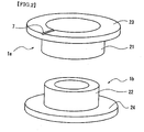
- Fig.2 shows the oblique view showing the first ring made of a metal 1a and the second ring made of a metal 1b and it was made clear that the fitting portion should have a cylindrical shape and its thickness should be not less than 1.5 mm considering the strength and the electrical resistance when fitted, and desirably, 2 to 3 mm, and that the lower limit of the thickness should be within the aforementioned range. Increasing the lower limit over the aforementioned range further improves strength and electrical resistance, however, the battery weight increases and high output is required for welding the fitting portion mentioned later and considering the bad effect caused by the temperature rise at the time of welding, as thickness of cylindrical portion, said designated range is appropriate.
- the length should be at least 3 mm. Therefore, it can be acknowledged that the pipe portion of the flange connection body inevitably has the length of not less than 3mm. However, to unnecessarily elongate the length causes the increase in electrical resistance at the connecting portion, and therefore, there is a reasonable upper limit. By this structure, the heating of the battery mentioned later can be inhibited.
- the thickness of flanges 23 and 24 of rings made of metal 1a and 1b which directly contact with the bottomed cylindrical battery case 2 which is also one electrode terminal or the sealing plate 3 which is also another electrode terminal at the time of integration by a spot welding is found to be effective for improvement in welding strength when said thickness is around 0.5 mm. Since this thickness is substantially the same as that of the material which composes a bottomed cylindrical battery case 2 and the sealing plate 3, it is desirable that the thickness of the flanges 23 and 24 is set to be substantially the same as that of the welded portion for securing the welding strength. Therefore, since the optimum value varies depending on the parts which compose the battery, the thickness of flanges 23 and 24 should be set based on the thickness of the bottomed cylindrical battery case 2 and the sealing plate 3.
- welding is available not only by the spot welding but also by the socalled inverter welding method using an inverter DC power source.
- stronger welding is available since structure of intensively applying a current to the protruded portion provided on the same radius of the welded surface of flanges 23 and 24 becomes available.
- the first ring made of a metal 1a can be directly welded in a bottomed cylindrical case 2 in the step before a power generating element and electrolyte are contained in the battery case 2.
- the second ring made of a metal 1b can be welded in a sealing plate 3.
- the welding part can be made firm.
- a ventilating groove 7 is hereby explained.
- a rubber valve 6 shown in Fig.1 is internally fitted in the sealing plate 3.
- the rubber valve 6 is deformed and the gas is exhausted from the inside.
- the ventilating groove 7 which can exhaust the gas outside is formed at least on one jointed surface of flanges 23 and 24.
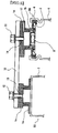
- the present invention by thickening the thickness of the cylindrical portions 21 and 22 of the first ring made of a metal 1a and the second ring made of a metal 1b, electrical resistance can be lowered. As a result, in the fitted state as shown in Fig.3, even when the distance A between flanges 23 and 24 is elongated, the ratio of the increase in electrical resistance becomes less. From this, as mentioned above, the laser welding is applicable to the fitting portion and further, since the structure in which at least one portion of the first ring made of a metal 1a and the second ring made of a metal 1b can be exposed is available, function with excellent heat radiation performance can be added.
- the fixing frame 18 is provided with the supporting portion 18a which can support on two portions or more thereby enabling welding of jointed portions or screw fitting portions and ventilating air.
- a screw groove (female screw) 8 is formed inside of a cylindrical portion of the first ring made of a metal 1a and a screw groove (male screw) 9 corresponding to the outside of a cylindrical portion of the second ring made of a metal 1b, thereby connecting the first ring made of a metal 1a and the second ring made of a metal 1b with a screw fitting as shown in Fig.4.
- a ventilating pore 17 is preferably provided on the second connector made of a metal 1 d to be fitted and screw fitted in the side with a sealing plate 3.
- Batteries to be measured are D sized batteries (cylindrical sealed batteries with an outer diameter of 17 mm and a height of 56 mm by the single size).
- the first ring made of a metal 1a was welded to a sealing plate 3 which is a positive electrode terminal.
- the thickness of a flange 23 of the first ring made of a metal 1a used here was 0.5 mm, and the outer diameter was 23 mm, the outer diameter of a cylindrical portion 21 was 17 mm, and the inner diameter was 13.8 mm.
- the second ring made of a metal 1b was welded to a bottom portion of a battery case 2 which is a negative electrode terminal.
- the thickness of a flange 24 of the second ring made of a metal 1b was 0.5 mm, and the outer diameter was 20 mm, and the outer diameter of a cylindrical portion 22 was 13.7 mm, and the inner diameter of was 10 mm.
- a connection system, the presence or absence of copper foils and of laser welding are as shown in the table 1.
- a metal foil used for lowering the electrical resistance of a fitting portion and a screw fitting portion a copper foil with a thickness of 20 ⁇ m was used.
- a laser welder manufactured by MIYACHI CORPORATION: type ML-2550A
- irradiation was applied for 0.1 second with an irradiating diameter of 0.6mm and with an output of 5.4kW.
- a female screw of M16 When connected by screw fitting, a female screw of M16 is formed in an inner side surface of a cylindrical portion of the first ring made of a metal 1a and a male screw of M16 is formed in an outer side surface of a cylindrical portion of the second ring made of a metal 1b.
- Table 1 Result of measurement of electrical resistance of a connection method and of a connection portion Connection system The presence of copper foil at a connecting portion Laser welding Electrical resistance at the connecting portion (m ⁇ ) Yes or No Number of laser points Fitting method Present Not present No -- 1.31 -- 0.81 Not present Yes 4 0.56 6 0.51 8 0.49 Screw fitting method Not present Present No -- 1.55 -- 0.82 Not present Yes 4 0.58 6 0.52 8 0.50
- the value of resistance when simply fitted or screw fitted was 1.31 to 1.55 m ⁇ . This value has no bad effect from the practical view point judging from that the voltage decreases by 65.5 to 77.5 mV when 50 A of current is applied by a nickel cadmium battery or nickel hydroxide battery practically used as a battery for large current and that the operation voltage of the battery is 1.2 V, the voltage decreases by more than 5 %.
Landscapes
- Chemical & Material Sciences (AREA)
- Chemical Kinetics & Catalysis (AREA)
- Electrochemistry (AREA)
- General Chemical & Material Sciences (AREA)
- Connection Of Batteries Or Terminals (AREA)
Applications Claiming Priority (1)
| Application Number | Priority Date | Filing Date | Title |
|---|---|---|---|
| JP2005375324A JP5015455B2 (ja) | 2005-12-27 | 2005-12-27 | 二次電池単電池間の接続構造 |
Publications (2)
| Publication Number | Publication Date |
|---|---|
| EP1804312A2 true EP1804312A2 (fr) | 2007-07-04 |
| EP1804312A3 EP1804312A3 (fr) | 2010-06-30 |
Family
ID=37872180
Family Applications (1)
| Application Number | Title | Priority Date | Filing Date |
|---|---|---|---|
| EP06127238A Withdrawn EP1804312A3 (fr) | 2005-12-27 | 2006-12-27 | Structure de connexion entre les cellules unitaires |
Country Status (5)
| Country | Link |
|---|---|
| US (1) | US7887947B2 (fr) |
| EP (1) | EP1804312A3 (fr) |
| JP (1) | JP5015455B2 (fr) |
| KR (1) | KR100825908B1 (fr) |
| CN (1) | CN100565976C (fr) |
Cited By (5)
| Publication number | Priority date | Publication date | Assignee | Title |
|---|---|---|---|---|
| EP2253037A2 (fr) * | 2008-02-15 | 2010-11-24 | Atieva, Inc. | Procédé de connexion électrique de bornes de cellule dans un bloc-piles |
| US9892868B2 (en) | 2013-06-21 | 2018-02-13 | Ioxus, Inc. | Energy storage device assembly |
| US9899643B2 (en) | 2013-02-27 | 2018-02-20 | Ioxus, Inc. | Energy storage device assembly |
| CN109065825A (zh) * | 2018-07-27 | 2018-12-21 | 深圳市瑞德丰精密制造有限公司 | 铜铝复合极块的成型工艺 |
| EP3052842B1 (fr) * | 2013-09-30 | 2020-01-22 | Danfoss A/S | Procédé de fixation d'un objet à un boîtier de vanne |
Families Citing this family (10)
| Publication number | Priority date | Publication date | Assignee | Title |
|---|---|---|---|---|
| KR100913174B1 (ko) * | 2007-04-04 | 2009-08-19 | 삼성에스디아이 주식회사 | 전지 모듈 |
| JP5423431B2 (ja) * | 2010-01-27 | 2014-02-19 | トヨタ自動車株式会社 | 蓄電モジュールの連結構造及び蓄電モジュールの製造方法 |
| US20130095370A1 (en) * | 2010-06-14 | 2013-04-18 | Panasonic Corporation | Battery assembly production method and battery assembly |
| JP6433029B2 (ja) * | 2013-02-27 | 2018-12-05 | アイオクサス, インコーポレイテッドIoxus,Inc. | エネルギー蓄積デバイス組立体 |
| KR20140123693A (ko) * | 2013-04-15 | 2014-10-23 | 삼성에스디아이 주식회사 | 배터리 팩 |
| KR102381778B1 (ko) * | 2015-02-16 | 2022-04-01 | 삼성에스디아이 주식회사 | 배터리 팩 |
| DE102015207550A1 (de) | 2015-04-24 | 2016-10-27 | Robert Bosch Gmbh | Zellverbinder mit Toleranzausgleich |
| CN107994197B (zh) * | 2017-11-24 | 2023-07-07 | 晶丰电子封装材料(武汉)有限公司 | 一种柱式可充电电池与基座的连接结构及连接方法 |
| KR102434896B1 (ko) | 2017-12-21 | 2022-08-22 | 주식회사 엘지에너지솔루션 | 전지들의 직렬 연결을 위한 전지 커넥터 및 이를 포함하는 전지팩 |
| DE102019200349A1 (de) * | 2019-01-14 | 2020-07-16 | Robert Bosch Gmbh | Batteriezellenverbinder zur seriellen Verschaltung von Batteriezellen |
Citations (2)
| Publication number | Priority date | Publication date | Assignee | Title |
|---|---|---|---|---|
| GB108849A (en) * | 1916-08-08 | 1918-02-28 | Svenska Ackumulator Ab | Improvements in Electric Batteries. |
| DE494929C (de) * | 1929-01-30 | 1930-03-31 | Gerhard Jaeger | Trockenbatterie mit mehreren hintereinandergeschalteten Elementen |
Family Cites Families (15)
| Publication number | Priority date | Publication date | Assignee | Title |
|---|---|---|---|---|
| JPS51162935U (fr) * | 1975-06-19 | 1976-12-25 | ||
| US4077268A (en) * | 1976-07-14 | 1978-03-07 | Hill John W | Garage door operator |
| JPS5564273U (fr) * | 1978-10-27 | 1980-05-01 | ||
| US4746220A (en) * | 1985-04-18 | 1988-05-24 | Noritake Co., Limited | Screw type extruding or kneading machine and screw used therein |
| JP2801922B2 (ja) * | 1989-03-29 | 1998-09-21 | 旭化成工業株式会社 | 非水系電池、およびそのリードタブの溶接方法 |
| JPH08222201A (ja) * | 1995-02-14 | 1996-08-30 | Toyota Autom Loom Works Ltd | 電 池 |
| JP3312853B2 (ja) | 1996-09-26 | 2002-08-12 | 松下電器産業株式会社 | 電池間接続構造 |
| JP2000077057A (ja) * | 1998-08-28 | 2000-03-14 | Ngk Insulators Ltd | リチウム二次電池 |
| JP3092923B2 (ja) | 1998-09-01 | 2000-09-25 | 松下電器産業株式会社 | 電池間接続構造、その方法、電池、電池モジュール、その製造方法 |
| JP3733009B2 (ja) | 2000-03-30 | 2006-01-11 | 三洋電機株式会社 | 組電池の製造方法および製造装置 |
| JP3723433B2 (ja) * | 2000-03-30 | 2005-12-07 | 三洋電機株式会社 | 組電池およびその製造方法 |
| US6844110B2 (en) * | 2000-05-24 | 2005-01-18 | Ngk Insulators, Ltd. | Lithium secondary cell and assembly thereof |
| FR2819105B1 (fr) * | 2001-01-04 | 2004-06-18 | Cit Alcatel | Systeme de raccordement electrique de generateurs electrochimiques |
| JP4356314B2 (ja) * | 2002-12-20 | 2009-11-04 | パナソニック株式会社 | 電池及び組電池 |
| US20050281611A1 (en) * | 2004-06-17 | 2005-12-22 | Seals-It | Seal component for use with a spherical rod end assembly |
-
2005
- 2005-12-27 JP JP2005375324A patent/JP5015455B2/ja not_active Expired - Fee Related
-
2006
- 2006-03-31 KR KR1020060029865A patent/KR100825908B1/ko active IP Right Grant
- 2006-06-06 CN CNB2006100879067A patent/CN100565976C/zh not_active Expired - Fee Related
- 2006-12-26 US US11/645,784 patent/US7887947B2/en not_active Expired - Fee Related
- 2006-12-27 EP EP06127238A patent/EP1804312A3/fr not_active Withdrawn
Patent Citations (2)
| Publication number | Priority date | Publication date | Assignee | Title |
|---|---|---|---|---|
| GB108849A (en) * | 1916-08-08 | 1918-02-28 | Svenska Ackumulator Ab | Improvements in Electric Batteries. |
| DE494929C (de) * | 1929-01-30 | 1930-03-31 | Gerhard Jaeger | Trockenbatterie mit mehreren hintereinandergeschalteten Elementen |
Cited By (7)
| Publication number | Priority date | Publication date | Assignee | Title |
|---|---|---|---|---|
| EP2253037A2 (fr) * | 2008-02-15 | 2010-11-24 | Atieva, Inc. | Procédé de connexion électrique de bornes de cellule dans un bloc-piles |
| EP2253037A4 (fr) * | 2008-02-15 | 2014-03-12 | Atieva Inc | Procédé de connexion électrique de bornes de cellule dans un bloc-piles |
| US9899643B2 (en) | 2013-02-27 | 2018-02-20 | Ioxus, Inc. | Energy storage device assembly |
| US9892868B2 (en) | 2013-06-21 | 2018-02-13 | Ioxus, Inc. | Energy storage device assembly |
| EP3052842B1 (fr) * | 2013-09-30 | 2020-01-22 | Danfoss A/S | Procédé de fixation d'un objet à un boîtier de vanne |
| US10814426B2 (en) | 2013-09-30 | 2020-10-27 | Danfoss A/S | Method for attaching an object to a structure |
| CN109065825A (zh) * | 2018-07-27 | 2018-12-21 | 深圳市瑞德丰精密制造有限公司 | 铜铝复合极块的成型工艺 |
Also Published As
| Publication number | Publication date |
|---|---|
| JP5015455B2 (ja) | 2012-08-29 |
| US7887947B2 (en) | 2011-02-15 |
| CN100565976C (zh) | 2009-12-02 |
| JP2007179816A (ja) | 2007-07-12 |
| KR20070068976A (ko) | 2007-07-02 |
| EP1804312A3 (fr) | 2010-06-30 |
| US20070184342A1 (en) | 2007-08-09 |
| CN1992389A (zh) | 2007-07-04 |
| KR100825908B1 (ko) | 2008-04-29 |
Similar Documents
| Publication | Publication Date | Title |
|---|---|---|
| US7887947B2 (en) | Connection structure between unit cells | |
| US7785377B2 (en) | Sealed battery and method for manufacturing the same | |
| US8404380B2 (en) | Inter-connector between unit cells and serial cell | |
| JP5528746B2 (ja) | 組電池 | |
| US9653722B2 (en) | Prismatic secondary battery | |
| US8211565B2 (en) | Secondary battery for medium and large size battery module | |
| US11108117B2 (en) | Sealed battery, battery module, and method of manufacturing battery module | |
| EP2228848A1 (fr) | Accumulateur de type cylindrique avec protection des languettes d'électrode | |
| KR20150014461A (ko) | 리튬 축전 배터리용 터미널 형성용 부싱 및 관련된 축전 배터리 | |
| EP3664181B1 (fr) | Batterie rechargeable cylindrique ayant une structure destinée à protéger contre un faisceau laser pour un soudage, et bloc-batterie comprenant cette dernière | |
| CN112838334B (zh) | 密闭型电池 | |
| US20240170809A1 (en) | Tab welding method, welding tool, battery cell, battery, and electric device | |
| JP7332999B2 (ja) | 密閉型電池 | |
| KR20150135163A (ko) | 고용량, 고출력 리튬이온전지 캡조립체 | |
| US20220085464A1 (en) | Terminal, secondary battery provided with same, and methods for producing same | |
| JP6994156B2 (ja) | 密閉型電池 | |
| CN217361685U (zh) | 电池、及包括该电池的电池组和车辆 | |
| KR101201815B1 (ko) | 이차 전지 | |
| US20220085469A1 (en) | Terminal for secondary battery and secondary battery provided with the terminal | |
| JP6764569B2 (ja) | 密閉型電池 | |
| KR20240034660A (ko) | 전지 및 전지의 제조 방법 | |
| JP4665427B2 (ja) | 扁平型密閉電池 | |
| KR20230057963A (ko) | 이차 전지 | |
| KR101583443B1 (ko) | 고용량, 고출력 리튬이온전지 캡조립체의 제조방법 | |
| CN117477253A (zh) | 端子及具备该端子的电池 |
Legal Events
| Date | Code | Title | Description |
|---|---|---|---|
| PUAI | Public reference made under article 153(3) epc to a published international application that has entered the european phase |
Free format text: ORIGINAL CODE: 0009012 |
|
| AK | Designated contracting states |
Kind code of ref document: A2 Designated state(s): AT BE BG CH CY CZ DE DK EE ES FI FR GB GR HU IE IS IT LI LT LU LV MC NL PL PT RO SE SI SK TR |
|
| AX | Request for extension of the european patent |
Extension state: AL BA HR MK YU |
|
| PUAL | Search report despatched |
Free format text: ORIGINAL CODE: 0009013 |
|
| AK | Designated contracting states |
Kind code of ref document: A3 Designated state(s): AT BE BG CH CY CZ DE DK EE ES FI FR GB GR HU IE IS IT LI LT LU LV MC NL PL PT RO SE SI SK TR |
|
| AX | Request for extension of the european patent |
Extension state: AL BA HR MK RS |
|
| 17P | Request for examination filed |
Effective date: 20101112 |
|
| AKX | Designation fees paid |
Designated state(s): FR |
|
| REG | Reference to a national code |
Ref country code: DE Ref legal event code: R108 Effective date: 20110208 Ref country code: DE Ref legal event code: 8566 |
|
| STAA | Information on the status of an ep patent application or granted ep patent |
Free format text: STATUS: THE APPLICATION IS DEEMED TO BE WITHDRAWN |
|
| 18D | Application deemed to be withdrawn |
Effective date: 20130702 |