EP1803878A2 - Decompression closure - Google Patents
Decompression closure Download PDFInfo
- Publication number
- EP1803878A2 EP1803878A2 EP20060026132 EP06026132A EP1803878A2 EP 1803878 A2 EP1803878 A2 EP 1803878A2 EP 20060026132 EP20060026132 EP 20060026132 EP 06026132 A EP06026132 A EP 06026132A EP 1803878 A2 EP1803878 A2 EP 1803878A2
- Authority
- EP
- European Patent Office
- Prior art keywords
- spring
- arrangement according
- bearing carriage
- decompression
- closure
- Prior art date
- Legal status (The legal status is an assumption and is not a legal conclusion. Google has not performed a legal analysis and makes no representation as to the accuracy of the status listed.)
- Granted
Links
- 230000006837 decompression Effects 0.000 title claims abstract description 60
- 238000006073 displacement reaction Methods 0.000 claims abstract description 9
- 239000004033 plastic Substances 0.000 claims description 14
- 229910052751 metal Inorganic materials 0.000 claims description 12
- 239000002184 metal Substances 0.000 claims description 12
- 230000006835 compression Effects 0.000 claims description 10
- 238000007906 compression Methods 0.000 claims description 10
- 125000006850 spacer group Chemical group 0.000 claims description 9
- 229910052782 aluminium Inorganic materials 0.000 claims description 2
- XAGFODPZIPBFFR-UHFFFAOYSA-N aluminium Chemical compound [Al] XAGFODPZIPBFFR-UHFFFAOYSA-N 0.000 claims description 2
- 230000006378 damage Effects 0.000 claims description 2
- 239000004696 Poly ether ether ketone Substances 0.000 claims 2
- 229920002530 polyetherether ketone Polymers 0.000 claims 2
- JUPQTSLXMOCDHR-UHFFFAOYSA-N benzene-1,4-diol;bis(4-fluorophenyl)methanone Chemical compound OC1=CC=C(O)C=C1.C1=CC(F)=CC=C1C(=O)C1=CC=C(F)C=C1 JUPQTSLXMOCDHR-UHFFFAOYSA-N 0.000 claims 1
- 210000003746 feather Anatomy 0.000 claims 1
- 238000010276 construction Methods 0.000 description 4
- 238000007789 sealing Methods 0.000 description 3
- 229910000639 Spring steel Inorganic materials 0.000 description 1
- 238000011161 development Methods 0.000 description 1
- 230000018109 developmental process Effects 0.000 description 1
- 230000008030 elimination Effects 0.000 description 1
- 238000003379 elimination reaction Methods 0.000 description 1
- 239000000463 material Substances 0.000 description 1
- 238000000034 method Methods 0.000 description 1
- 210000001331 nose Anatomy 0.000 description 1
- 229920000642 polymer Polymers 0.000 description 1
- 239000000047 product Substances 0.000 description 1
- 239000013589 supplement Substances 0.000 description 1
- 239000013585 weight reducing agent Substances 0.000 description 1
Images


Classifications
-
- E—FIXED CONSTRUCTIONS
- E05—LOCKS; KEYS; WINDOW OR DOOR FITTINGS; SAFES
- E05B—LOCKS; ACCESSORIES THEREFOR; HANDCUFFS
- E05B51/00—Operating or controlling locks or other fastening devices by other non-mechanical means
- E05B51/02—Operating or controlling locks or other fastening devices by other non-mechanical means by pneumatic or hydraulic means
- E05B51/023—Operating or controlling locks or other fastening devices by other non-mechanical means by pneumatic or hydraulic means actuated in response to external pressure, blast or explosion
-
- B—PERFORMING OPERATIONS; TRANSPORTING
- B64—AIRCRAFT; AVIATION; COSMONAUTICS
- B64C—AEROPLANES; HELICOPTERS
- B64C1/00—Fuselages; Constructional features common to fuselages, wings, stabilising surfaces or the like
- B64C1/18—Floors
-
- E—FIXED CONSTRUCTIONS
- E05—LOCKS; KEYS; WINDOW OR DOOR FITTINGS; SAFES
- E05C—BOLTS OR FASTENING DEVICES FOR WINGS, SPECIALLY FOR DOORS OR WINDOWS
- E05C5/00—Fastening devices with bolts moving otherwise than only rectilinearly and only pivotally or rotatively
- E05C5/02—Fastening devices with bolts moving otherwise than only rectilinearly and only pivotally or rotatively both moving axially and turning about their axis to secure the wing
-
- B—PERFORMING OPERATIONS; TRANSPORTING
- B64—AIRCRAFT; AVIATION; COSMONAUTICS
- B64C—AEROPLANES; HELICOPTERS
- B64C1/00—Fuselages; Constructional features common to fuselages, wings, stabilising surfaces or the like
- B64C2001/009—Fuselages; Constructional features common to fuselages, wings, stabilising surfaces or the like comprising decompression panels or valves for pressure equalisation in fuselages or floors
-
- E—FIXED CONSTRUCTIONS
- E05—LOCKS; KEYS; WINDOW OR DOOR FITTINGS; SAFES
- E05B—LOCKS; ACCESSORIES THEREFOR; HANDCUFFS
- E05B63/00—Locks or fastenings with special structural characteristics
- E05B63/0052—Locks mounted on the "frame" cooperating with means on the "wing"
-
- Y—GENERAL TAGGING OF NEW TECHNOLOGICAL DEVELOPMENTS; GENERAL TAGGING OF CROSS-SECTIONAL TECHNOLOGIES SPANNING OVER SEVERAL SECTIONS OF THE IPC; TECHNICAL SUBJECTS COVERED BY FORMER USPC CROSS-REFERENCE ART COLLECTIONS [XRACs] AND DIGESTS
- Y10—TECHNICAL SUBJECTS COVERED BY FORMER USPC
- Y10S—TECHNICAL SUBJECTS COVERED BY FORMER USPC CROSS-REFERENCE ART COLLECTIONS [XRACs] AND DIGESTS
- Y10S292/00—Closure fasteners
- Y10S292/65—Emergency or safety
-
- Y—GENERAL TAGGING OF NEW TECHNOLOGICAL DEVELOPMENTS; GENERAL TAGGING OF CROSS-SECTIONAL TECHNOLOGIES SPANNING OVER SEVERAL SECTIONS OF THE IPC; TECHNICAL SUBJECTS COVERED BY FORMER USPC CROSS-REFERENCE ART COLLECTIONS [XRACs] AND DIGESTS
- Y10—TECHNICAL SUBJECTS COVERED BY FORMER USPC
- Y10T—TECHNICAL SUBJECTS COVERED BY FORMER US CLASSIFICATION
- Y10T292/00—Closure fasteners
- Y10T292/08—Bolts
- Y10T292/0886—Sliding and swinging
-
- Y—GENERAL TAGGING OF NEW TECHNOLOGICAL DEVELOPMENTS; GENERAL TAGGING OF CROSS-SECTIONAL TECHNOLOGIES SPANNING OVER SEVERAL SECTIONS OF THE IPC; TECHNICAL SUBJECTS COVERED BY FORMER USPC CROSS-REFERENCE ART COLLECTIONS [XRACs] AND DIGESTS
- Y10—TECHNICAL SUBJECTS COVERED BY FORMER USPC
- Y10T—TECHNICAL SUBJECTS COVERED BY FORMER US CLASSIFICATION
- Y10T292/00—Closure fasteners
- Y10T292/08—Bolts
- Y10T292/1043—Swinging
- Y10T292/1075—Operating means
- Y10T292/1083—Rigid
Definitions
- the passage opening shutter plate is held at the edge each by a pivot lock latch L which is disposed on a bearing carriage Z of the decompression shutter X.
- the decompression closures X are fixed to the walls at the edges of the passage opening.
- the dissolved passage opening closure plate C (dashed line) can thereby be brought back into a position closing the passage opening by being pressed with its lower edge V on the upper sliding slope T of the pivot lock bolt L.
- the pivot lock bolt pivots in the direction opposite to -R until the leaf spring has returned to the latching position holding it. This process takes place with temporary deflection of the bearing carriage sideways in direction -D (against the force of the spiral spring).
- the coil spring returns the bearing carriage in a direction opposite to -D, with the outer end of the port closure latch L again in a closed position above the port port.
- the combined decompression closures are mounted on a (sealing) frame F ', which is arranged in the passage opening at the edge.
- the "outer” pivot lock L “of a decompression closure X” protrudes on the wall (W ') - top; the “inner” pivot lock L 'of the other decompression lock X' protrudes on the passage opening shutter (C ') top.
- the improvements relate to a weight reduction, simplification of assembly, a smaller number of individual parts, and thus also to a cost reduction.
- This decompression closure comprises a bearing carriage 3 and a base part 4.
- the bearing carriage 3 is reciprocable in straight grooves 5 (only one of these grooves can be seen in FIG. 1) of the base part 4.
- the bearing carriage 3 consists essentially of two side walls 3-1 and 3-2 and one of these in its lower part part connecting transverse plate 3-3; on it the pivot lock bolt 2 and the leaf spring 1 are arranged.
- the pivot lock bar 2 is rotatably supported on an axis A disposed between the side walls 3-1 and 3-2.
- the outwardly facing end of the swing lock bolt 2 has a sliding bevel S on which - as explained in connection with FIG.8 - the edge E of the passage opening closure plate slides along during opening, exerts a force and causes a pivoting and displacement of the bearing carriage ,
- a notch K is provided at the other end of the pivot lock bolt (see also FIG.2) at the other end of the pivot lock bolt (see also FIG.2) .
- notch K engages (locks) in the closed position of the swing lock bolt 2, the end 1-3 of the two-legged bent leaf spring 1 a.
- a spiral compression spring 6 is arranged in a recess 7 in the base part 4 below the bearing carriage 3.
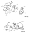
- FIG. 3A and FIG. 3B show perspective individual parts representations in two different directions of view of a bearing carriage 3 'of the decompression closure according to the invention in a two-part design.
- Both bearing slide parts 3-1 ', 3-2' each comprise a wall of the bearing carriage 3 '.
- the free ends e1, e2 and 23 of this Spacers in Aussparitch the wall of the bearing carriage part 3-2 'arranged.
- spacer elements have, for the remaining part of the spacer elements, a shoulder st1, st2, st3, which rests in the assembled bearing carriage on the inner wall of the bearing carriage part 3-2 '.
- the spacer d1 also forms the axis for the pivot lock bolt 2 '.
- FIG. 4 shows a perspective view of an assembly according to the invention 40 with two adjacent oppositely acting decompression closures 10 and 20th
- FIG. 5 shows a perspective view of this unit, in which for reasons of clarity, one of the decompression closures is not shown. This representation serves as a supplement to FIG. 4. The same parts bear the same reference numbers.
- the two decompression closures 10 and 20 (which in their construction with one exception correspond to the single compression closure according to FIG. 1) are arranged side by side on a common base part 30, acting in offset direction + F and + G.
- the exception is that both decompression closures 10 and 20 have a common spring 31 for the displacement of their bearing carriage 11 and 21.
- the outer end 12e of the swing lock latch 12 of one decompression lock 10 and the outer end 22e of the swing lock latch 22 of the other decompression lock 20 are offset in the opposite direction Directions + F and + G.
- the bearing slide guides of both decompression closures are parallel to each other.
- the groove guides for the decompression closure 10 are marked with 13.
- the bearing carriage 11 is pressed by this spring 31 in the + F direction, the bearing carriage 21 in the + G direction in an end position.
- the end position of the bearing carriage 11 is defined by the stop 32 (FIG. 5).
- the pivot lock 12 and 21 in the locking position when the corresponding leaf spring 14 and 24 engages in its retaining notch K (see also FIG 6).
- the two decompression closures 10 and 20 common coil spring 31 is arranged.
- a stopper is provided in each case.
- the stopper for the front end 31a is formed as a projection 23 on the side of the bearing carriage 21; the stop for its rear end 31b (not visible in FIGS. 4, 5 and 6) is correspondingly designed as a projection on the side of the bearing carriage 11.
- the imaginary axis of the compression spring extends parallel to the direction of displacement of the bearing carriage 11 and 21st
- the single decompression cap according to the invention is suitable for opening a porthole closure plate in one direction only, which may also be hinged.
- Decompression closures are used wherever rapid compensation of different pressures in two separate areas is required, especially in aircraft construction. Since in aircraft very high demands are placed on the heat resistance of parts, related decompression closures made of metal, preferably made of aluminum (die-cast), except the springs, for which spring steel is used anyway. For such decompression closures, a two-part construction is particularly advantageous because it requires a very advantageous assembly. With not too high requirements for heat resistance
- the decompression closures can also be made as plastic.
- the plastic material makes it possible to form spring lugs (p2 in FIG. 2) for fixing the retaining leaf spring in the plastic side walls of the bearing carriage, in particular in a one-piece design, ie resilient projections by means of which the retaining leaf spring can be fixed in position ,
- FIG.6 shows an individual perspective view of the assembly of the invention according to FIG. 4 with two adjacent opposing decompression closures.
- the items bear the same reference numerals as in FIGS. 4 and 5.
- FIG. 7A shows a perspective view of a arranged in an opening OP (FIG.7C) of a wall WA fürlouö Stammels HC with a (sealing) frame FR, on the units according to the invention for two adjacent oppositely acting decompression closures according to FIG. 4 are arranged.
- FIG. 7B shows a perspective view of the pushed into the upper area O fürlouö Stammels HC.
- FIG.7C shows a perspective view of the pressed into the lower region U with frame FR fürlouö Stammels HC.
- FIG. 7A, 7B and 7C serve to illustrate the schematic sectional view in FIG. 9 to the operation of the assembly with two adjacent in opposite directions acting decompression closures clearly supplemented by a perspective view.
- FIGS. Figures 7A, 7B and 7C are decompression closures according to the invention (indicated by the common spring 31 between the two bearing carriages (detail A in Figure 7A)).
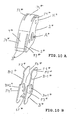
- FIG. 10A shows a perspective view of a pivot lock bolt 2 * consisting of a metal skeleton B * overmoulded with plastic PL *.
- FIG. 10B shows a perspective view of this metal skeleton B *.
- the metal skeleton is more resistant to heat than the plastic.
- the metal skeleton B * is designed such that, after heat-related destruction of the plastic - eg as a result of fire - the function of the pivot lock bolt maintains its pivotability about the axis A *, the Kraftbeetzschlagiana the sliding bevels S *, T * and the leaf spring -related detent position K *.
- the metal skeleton B * comprises two mutually parallel planar Wandelemenete B-1 *, B-2 *, which are interconnected by a web ST *, and having aligned bores BH1 *, BH2 * for receiving the pivot axis A *.
- the edge surfaces F1 *, F2 *, F3 *, F4 *; F5 *, F6 * of the wall elements are located on the surface of the area of the sliding bevels or on the surface of the latch area. These edge surfaces form a smooth surface with the adjacent plastic edge surfaces. These edge surfaces can also be provided with a thin plastic pad.
- the layer thickness must - if appropriate heat-related product requirements exist- be sized so that after heat-related elimination of the plastic, the sliding and pivoting function of the swing lock bolt is not affected.
Abstract
Description
Sogenannte Dekompressionsverschlüsse werden benötigt, um bei einem plötzlichen Druckanstieg in einem von 2 Bereichen einen schnellen Druckausgleich zu ermöglichen.So-called decompression closures are needed to allow rapid pressure equalization in the event of a sudden increase in pressure in one of 2 areas.
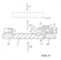
Die Funktion eines Dekompressionsverschlusses wird an folgendem Beispiel (FIG.8) erläutert:
- Zwei Bereiche (ein oberer Bereich O und ein unterer Bereich U) sind durch eine Wand W voneinander abgedichtet getrennt. In der Wand W ist lösbar eine Durchlaßöffnungs-Verschlußplatte C (hatch cover) abgedichtet angeordnet.
- Two areas (an upper area O and a lower area U) are separated from each other by a wall W. In the wall W is releasably arranged a passage opening closure plate C (hatch cover) sealed.
In beiden Bereichen O und U herrscht üblicherweise der gleiche Druck; tritt jetzt im unteren Bereich U eine Druckerhöhung auf, wird ( bei Erreichung eines bestimmten Druckwertes) die Durchlaßöffnungs-Verschlußplatte C in Richtung +P in den oberen Bereich O "geschleudert" (gedrückt), so daß durch die dann nicht mehr verschlossene Durchlaßöffnung ein schneller Druckausgleich erfolgen kann.In both areas O and U usually the same pressure prevails; If an increase in pressure now occurs in the lower region U, (when a certain pressure value has been reached) the passage opening closure plate C is "thrown" (pressed) in the direction + P into the upper region O, so that a faster passage through the then no longer closed passage opening Pressure equalization can be done.
Die Durchlaßöffnungs-Verschlußplatte wird randwärts jeweils von einem Schwenkverschluß-Riegel L gehalten, der auf einem Lagerschlitten Z des Dekompressionsverschlusses X angeordnet ist. Die Dekompressionverschlüsse X sind an den Rändern der Durchlaßöffnung an der Wand befestigt.
Wenn die Durchlaßöffnungs-Verschlußplatte C durch den Druckanstieg im unteren Bereich U in Richtung +P gegen den Schwenkverschluß-Riegel L drückt, löst sich eine diesen Riegel haltende Blattfeder (nicht dargestellt) aus einer Rastposition, und der Schwenkverschluß-Riegel L schwenkt in Richtung +R um die Achse A. Dabei drückt die obere Kante E der Durchlaßöffnungs-Verschlußplatte C gegen die Schräge S des Schwenkverschluß-Riegels L und verschiebt dabei den Lagerschlitten Z des Dekompressionsverschlusses X vorübergehend seitwärts in Richtung -D gegen die Kraft einer Spiral-Feder (nicht dargestellt).
Dadurch ist der Weg für die Durchlaßöffnungs-Verschlußplatte C in den oberen Bereich O freigegeben.The passage opening shutter plate is held at the edge each by a pivot lock latch L which is disposed on a bearing carriage Z of the decompression shutter X. The decompression closures X are fixed to the walls at the edges of the passage opening.
When the passage opening shutter plate C presses against the swing shutter latch L by the pressure increase in the lower region U in the direction + P, a leaf spring (not shown) holding this latch disengages from a detent position, and the swing-lock latch L pivots in direction + R about the axis A. At this time, the upper edge E of the port-opening shutter C presses against the slope S of the swing-latch L, temporarily displacing the carriage Z of the decompression shutter X sideways in the direction of D against the force of a spiral spring (not shown).
Thereby, the way for the passage opening shutter plate C in the upper area O is released.
Die gelöste Durchlaßöffnungs-Verschlußplatte C (gestrichelte Darstellung) kann dadurch wieder in eine die Durchlaßöffnung verschließende Position gebracht werden, indem sie mit ihrer unteren Kante V auf die obere Gleitschräge T des Schwenkverschluß-Riegels L gedrückt wird.
Dabei schwenkt der Schwenkverschluß-Riegel in Richtung entgegengesetzt zu -R , bis die Blattfeder wieder in die ihn haltende Rastposition gelangt ist. Dieser Vorgang erfolgt unter vorübergehendem Ausweichen des Lagerschlittens seitwärts in Richtung -D (gegen die Kraft der Spiralfeder).
Sobald die Durchlaßöffnungs-Verschlußplatte in eine die Durchlaßöffnung verschließende Position gelangt ist, drückt die Spiralfeder den Lagerschlitten in eine Richtung entgegengesetzt zu -D zurück, wobei das äußere Ende des Schwenkverschluß-Riegels L über der Durchlaßöffnungsverschluß-Platte wieder eine Verschlußposition einnimmt.
Diese Funktionsweise des Dekompressionsverschlusses bezieht sich sowohl auf den nachfolgend erwähnten Dekompressionsverschluß nach dem Stand der Technik gemäß
In this case, the pivot lock bolt pivots in the direction opposite to -R until the leaf spring has returned to the latching position holding it. This process takes place with temporary deflection of the bearing carriage sideways in direction -D (against the force of the spiral spring).
Once the port opening closure plate has entered a port closing position, the coil spring returns the bearing carriage in a direction opposite to -D, with the outer end of the port closure latch L again in a closed position above the port port.
This mode of operation of the decompression closure relates both to the decompression closure according to the prior art mentioned below
Bei entsprechender Kombination zweier entgegengesetzt wirkender Dekompressionsverschlüsse (s. FIG.9) zu einer Baueinheit - der Lagerschlitten des einen Dekompressionsverschlusses X' läßt sich seitwärts in Richtung -M, der Lagerschlitten des anderen Dekompressionsverschlusses X" läßt sich entgegengesetzt dazu in Richtung -N verschieben) - läßt sich erreichen,
daß die Durchlaßöffnungs-Verschlußplatte C' bei Druckanstieg im unteren Bereich U' in den oberen Bereich O' in Richtung +P' "geschleudert" (gedrückt) wird oder
daß die Durchlaßöffnungs-Verschlußplatte C' bei Druckanstieg im oberen Bereich O' in den unteren Bereich U' in Richtung -P' "geschleudert" wird, damit ein Druckausgleich erfolgen kann.With a suitable combination of two oppositely acting decompression closures (see FIG.9) to a structural unit - the bearing carriage of a decompression closure X 'leaves sideways towards -M, the bearing carriage of the other decompression stop X "can be opposite to move in the direction of -N) - can be achieved
that the passage opening shutter plate C 'in pressure increase in the lower region U' in the upper area O 'in the direction + P'"flung" (pressed) or
that the Durchlaßöffnungs-closure plate C 'at pressure rise in the upper region O' in the lower region U 'in the direction -P'"spun", so that a pressure equalization can take place.
Zu diesem Zweck sind die kombinierten Dekompressionsverschlüsse auf einem (Dichtungs-)Rahmen F' befestigt, welcher randwärts in der Durchlaßöffnung angeordnet ist. Der "äußere" Schwenkverschluß-Riegel L" des einen Dekompressionsverschlusses X" ragt auf die Wand (W')-Oberseite; der "innere" Schwenkverschluß-Riegel L' des anderen Dekompressionsverschlusses X' ragt auf die Durchlaßöffnungs-Verschlußplatten (C')-Oberseite.For this purpose, the combined decompression closures are mounted on a (sealing) frame F ', which is arranged in the passage opening at the edge. The "outer" pivot lock L "of a decompression closure X" protrudes on the wall (W ') - top; the "inner" pivot lock L 'of the other decompression lock X' protrudes on the passage opening shutter (C ') top.
Bei Druckanstieg im unteren Bereich U' öffnen die inneren Riegel L' und der Durchlaßöffnungs-Deckel C' wird in den oberen Bereich O' "geschleudert" (gedrückt).
Bei Druckanstieg im oberen Bereich O' öffnen die aüßeren Riegel L" und der Durchlaßöffnungs-Deckel C' samt Rahmen F' wird in den unteren Bereich U' (gedrückt).When the pressure increases in the lower area U ', the inner latches L' open and the Durchlaßöffnungs cover C 'is in the upper area O'"flung" (pressed).
When the pressure rises in the upper area O ', the outer bars L "open and the passage opening lid C' together with the frame F 'is pushed into the lower area U' (pressed).
Aus der
Dabei ist die Druckfeder in einer Wanne unterhalb des Lagerschlittens in einer Grundplatte angeordnet. Am Lagerschlitten ist eine Rastfeder befestigt. Ihr äußeres Ende hält den Verschlußriegel in Schließstellung, ihr inneres Ende ist derart in die Wanne an das Ende der Druckfeder geführt, daß sie die Verbindung zwischen Druckfeder und Lagerschlitten herstellt.
In dieser
The compression spring is arranged in a trough below the bearing carriage in a base plate. On the bearing carriage a detent spring is attached. Your outer end holds the locking latch in the closed position, its inner end is guided in such a way in the tub to the end of the compression spring, that it establishes the connection between compression spring and bearing carriage.
In this
Es ist Aufgabe der Erfindung, einen verbesserten Dekompressionsverschluß vorzusehen bzw. eine verbesserte Baueinheit mit zwei nebeneinanderliegenden entgegengesetzt wirkenden Dekompressionsverschlüssen vorzusehen.It is an object of the invention to provide an improved decompression closure or to provide an improved assembly with two adjacent oppositely acting decompression closures.
Diese Aufgabe wird durch die in den Ansprüchen 1 bzw. 8 angegebenen kennzeichnenden Merkmale gelöst.This object is achieved by the characterizing features specified in
Vorteilhafte Weiterbildungen sind in den Unteransprüchen gekennzeichnet.Advantageous developments are characterized in the subclaims.
Die Verbesserungen beziehen sich auf eine Gewichtsreduzierung, Montagevereinfachung, eine geringere Anzahl von Einzelteilen, und somit auch auf eine Kostenreduzierung.The improvements relate to a weight reduction, simplification of assembly, a smaller number of individual parts, and thus also to a cost reduction.
Ausführungsbeispiele der Erfindung sind in den Zeichnungen dargestellt und werden im folgenden näher beschrieben.Embodiments of the invention are illustrated in the drawings and will be described in more detail below.
Es zeigen:
- FIG. 1
eine perspektivische Darstellung eines erfindungsgemäßen Einzel-Dekompressionsverschlusses; - FIG. 2
eine Schnittdarstellung des erfindungsgemäßen Einzel-Dekompressionsverschlusses gemäß FIG.1; - FIG.3A, FIG. 3B
perspektivische Einzelteildarstellungen in zwei verschiedenen Blickrichtungen von einem Lagerschlitten in zweigeteilter Bauweise für den erfindungsgemäßen Dekompressionsverschluß; - FIG.4
eine perspektivische Darstellung einer erfindungsgemäßen Baueinheit mit zwei nebeneinanderliegenden entgegengesetzt wirkenden Dekompressionsverschlüssen; - FIG.5
eine perspektivische Darstellung einer erfindungsgemäßen Baueinheit für zwei nebeneinanderliegende entgegengesetzt wirkende Dekompressionsverschlüsse, von denen nur einer dargestellt ist; - FIG.6
eine perspektivische Einzelteildarstellung der erfindungsgemäßen Baueinheit gemäß FIG. 4 mit zwei nebeneinanderliegenden entgegengesetzt wirkenden Dekompressionsverschlüssen; - FIG. 7A
eine perspektivische Darstellung eines in einer Wandungsöffnung angeordneten Durchlaßöffnungs-Deckels mit einem Rahmen, auf dem erfindungsgemäße Baueinheiten für zwei nebeneinanderliegende entgegengesetzt wirkende Dekompressionsverschlüsse gemäß FIG. 4 angeordnet sind; - FIG. 7B
eine perspektivische Darstellung des in den oberen Bereich katapultierten Durchlaßöffnungs-Deckels mit Bezug auf FIG. 7A; - FIG. 7C
eine perspektivische Darstellung des in den unteren Bereich mit Rahmen katapultierten Durchlaßöffnungs-Deckels mit Bezug auf FIG.7B; - FIG.8
eine schematische Schnittdarstellung eines in einer Wandungsöffnung angeordneten Durchlaßöffnungs-Deckels mit Einzel-Dekompressions-Verschlüssen zur Erklärung der Wirkungsweise nach dem Stand der Technik; - FIG.9
eine schematische Schnittdarstellung eines in einer Wandungsöffnung mit Rahmen angeordneten Durchlaßöffnungs-Deckels zur Erklärung der Wirkungsweise nach dem Stand der Technik, wobei auf dem Rahmen Baueinheiten mit mit zwei nebeneinanderliegenden entgegengesetzt wirkenden Dekompressionsverschlüssen angeordnet sind. - FIG. 10A
eine perspektivische Darstellung eines Schenkverschluß-Riegels, bestehend aus einem mit Kunststoff umspritzten Metallskeletts. - FIG. 10B
eine perspektivische darstellung des Metallskeletts des Schwenkverschluß-Riegels gemäß FIG. 10A - FIG. 1 zeigt
eine perspektivische Darstellung eines erfindungsgemäßen Einzel-Dekompressionsverschlusses; - FIG. 2 eine Schnittdarstellung dieses Dekompressionsverschlusses.
- FIG. 1
a perspective view of a single decompression closure according to the invention; - FIG. 2
a sectional view of the individual decompression closure according to the invention according to FIG.1; - FIG. 3A, FIG. 3B
perspective individual parts representations in two different directions of view of a bearing carriage in two-part construction for the decompression according to the invention; - FIG.4
a perspective view of an assembly according to the invention with two adjacent oppositely acting decompression closures; - FIG.5
a perspective view of an assembly according to the invention for two adjacent oppositely acting decompression closures, of which only one is shown; - FIG.6
an individual perspective view of the assembly of the invention according to FIG. 4 with two adjacent oppositely acting decompression closures; - FIG. 7A
a perspective view of a arranged in a wall opening passage opening cover with a frame on which units according to the invention for two juxtaposed oppositely acting decompression closures according to FIG. 4 are arranged; - FIG. 7B
a perspective view of the catapulted in the upper region Durchlaßöffnungsdeckels with reference to FIG. 7A; - FIG. 7C
a perspective view of the catapulted in the lower area with passage through opening cover with reference to FIG. 7B; - FIG.8
a schematic sectional view of a arranged in a wall opening passage opening lid with single-decompression closures to explain the operation of the prior art; - FIG.9
a schematic sectional view of a arranged in a wall opening with frame passage opening lid to explain the operation of the prior art, wherein on the frame units are arranged with two adjacent oppositely acting Dekompressionsverschlüssen. - FIG. 10A
a perspective view of a Schenkverschluß-bolt, consisting of a plastic over-molded metal skeleton. - FIG. 10B
a perspective view of the metal skeleton of the pivot lock bolt according to FIG. 10A - FIG. 1 shows
a perspective view of a single decompression closure according to the invention; - FIG. 2 is a sectional view of this decompression closure.
Dieser Dekompressionsverschluß umfaßt einen Lagerschlitten 3 und ein Basisteil 4.This decompression closure comprises a bearing
Der Lagerschlitten 3 ist in geradgeführten Nuten 5 ( in FIG. 1 ist nur eine dieser Nuten erkennbar) des Basisteils 4 hin- und herbeweglich.The bearing
Der Lagerschlitten 3 besteht im wesentlichen aus zwei Seitenwänden 3-1 und 3-2 und einer diese in seinem unteren Bereich Teil verbindende Querplatte 3-3; auf ihm sind der Schwenkverschluß-Riegel 2 und die Blatt-Feder 1 angeordnet. Der Schwenkverschluß-Riegel 2 ist auf einer zwischen den Seitenwänden 3-1 und 3-2 angeordneten Achse A drehbar gelagert. Das nach außen weisende Ende des Schwenkverschluß-Riegels 2 hat eine Gleitschräge S, auf der - wie im Zusammenhang mit FIG.8 erläutert- beim Öffnungsvorgang die Kante E der Durchlaßöffnungs-Verschlußplatte entlanggleitet, dabei eine Kraft ausübt und eine Schwenkung und Verschiebung des Lagerschlittens bewirkt.The bearing
Am anderen Ende des Schwenkverschluß-Riegels (s. auch FIG.2) ist eine Kerbe K vorgesehen. In diese Kerbe K greift (rastet) in Verschlußstellung des Schwenkverschluß-Riegels 2 das Ende 1-3 der zweischenklig gebogenen Blattfeder 1 ein.At the other end of the pivot lock bolt (see also FIG.2) a notch K is provided. In this notch K engages (locks) in the closed position of the
Es ist Aufgabe der Rastfeder, durch Einrasten ihres Endes in die Kerbe des Schwenkverschluß-Riegels diesen in Schließstellung zu halten. Diese Rastverbindung ist lösbar. Der eine Schenkel 1-1 der Blattfeder 1 beaufschlagt federnd den Schwenkverschluß-Riegel 2; der andere Schenkel 1-2 dient ausschließlich der Fixierung der Blattfeder 1 im Lagerschlitten 3; er ist in diesem verschiebe- und abhebesicher angeordnet.It is the task of the detent spring to hold by snapping its end in the notch of the swing lock bolt this in the closed position. This locking connection is detachable. One leg 1-1 of the
Es ist Aufgabe der Blattfeder 1, durch Eingriff ihres Endes 1-3 in die Kerbe K des Schwenkverschluß-Riegels 2 diesen in Schließstellung zu halten.
Im Basisteil 4 ist in einer Aussparung 7 im Basisteil 4 unterhalb des Lagerschlittens 3 eine Spiral-Druckfeder 6 angeordnet.It is the task of the
In the base part 4, a
Es ist Aufgabe dieser Druckfeder 6, den Lagerschlitten 3 in die äußere Schließstellung (in Richtung -D gemäß FIG. 8) zu drücken.It is the task of this
Nachfolgend wird unter Einbeziehung von FIG.8 die Wirkungsweise dieses Dekompressionsverschlusses beschrieben:
In Schließstellung ragt das Ende des Schwenkverschluß-Riegels 2 über den Rand der Durchlaßöffnungs-Verschlußplatte. Bei Ansteigen des Druckes im unteren Bereich U über einen bestimmten Wert weicht die Durchlaßöffnungs-Verschlußplatte C in Richtung +P nach oben aus; dabei drückt ihre obere Kante E gegen die Gleitschräge S des Schwenkverschluß-Riegels 2. Dieser führt dabei eine Schwenkbewegung um seine Achse A in Richtung +R aus, wobei die Blattfeder 1 aus der Kerbe K ausrastet. Der Druck der Kante E auf die Gleitschräge S bewirkt, daß sich nunmehr der Lagerschlitten 3 gegen den Druck der Spiralfeder 6 in Richtung -D verschiebt. Hierdurch wird das zuvor noch über die Durchlaßöffnungs-Verschlußplatte C ragende äußere Ende des Schwenkverschluß-Riegels 2 zurückgezogen und der Weg ist frei: Die Durchlaßöffnungs-Verschlußplatte C kann nun ungehindert in den oberen Bereich O ausweichen. Der Druckausgleich zwischen dem unteren U und dem oberen Bereich O kann nun schnell -über die nicht mehr verschlossene Durchlaßöffnung -erfolgen.The mode of action of this decompression closure is described below, including FIG.
In the closed position, the end of the
Die FIG. 3A und FIG. 3B zeigen
perspektivische Einzelteildarstellungen in zwei verschiedenen Blickrichtungen von einem Lagerschlitten 3' des erfindungsgemäßen Dekompressionsverschlusses in zweigeteilter Bauweise.
Beide Lagerschlittenteile 3-1', 3-2' umfassen jeweils eine Wand des Lagerschlittens 3'.
Von dem Lagerschlittenteil 3-1' gehen Abstandselemente d1, d2 und d3 für die Verbindung beider Lagerschlittenteile aus.
Um beide Lagerschlittenteile verdrehfest miteinander verbinden zu können, sind die freien Enden e1, e2 und 23 dieser Abstandselemente in Ausparungen der Wand des Lagerschlittenteils 3-2' angeordnet.
Diese freien Enden der Abstandselemente weisen zum übrigen Teil der Abstandselemente einen Absatz st1, st2, st3 auf,
welcher im zusammengebauten Lagerschlitten an der Innenwand des Lagerschlittenteils 3-2' anliegt.
Das Abstandselement d1 bildet zugleich die Achse für den Schwenkverschluß- Riegel 2'.The FIG. 3A and FIG. 3B show
perspective individual parts representations in two different directions of view of a bearing carriage 3 'of the decompression closure according to the invention in a two-part design.
Both bearing slide parts 3-1 ', 3-2' each comprise a wall of the bearing carriage 3 '.
From the bearing carriage part 3-1 'go distance elements d1, d2 and d3 for the connection of both bearing carriage parts.
In order to connect both bearing slide parts rotationally together, the free ends e1, e2 and 23 of this Spacers in Aussparungen the wall of the bearing carriage part 3-2 'arranged.
These free ends of the spacer elements have, for the remaining part of the spacer elements, a shoulder st1, st2, st3,
which rests in the assembled bearing carriage on the inner wall of the bearing carriage part 3-2 '.
The spacer d1 also forms the axis for the pivot lock bolt 2 '.
FIG.4 zeigt
eine perspektivische Darstellung einer erfindungsgemäßen Baueinheit 40 mit zwei nebeneinanderliegenden entgegengesetzt wirkenden Dekompressionsverschlüssen 10 und 20.FIG. 4 shows
a perspective view of an assembly according to the
FIG. 5 zeigt
eine perspektivische Darstellung dieser Baueinheit, bei der aus Übersichtsgründen einer der Dekompressionsverschlüsse nicht mit dargestellt ist.
Diese Darstellung dient als Ergänzung zu FIG. 4. Dieselben Teile tragen dieselben Bezugszeichen.FIG. 5 shows
a perspective view of this unit, in which for reasons of clarity, one of the decompression closures is not shown.
This representation serves as a supplement to FIG. 4. The same parts bear the same reference numbers.
Die beiden Dekompressions-Verschlüsse 10 und 20 (welche in ihrer Bauart mit einer Ausnahme dem Einzelkompressionsverschluß gemäß FIG.1 entsprechen) sind nebeneinander - in versetzt entgegengerichteter Richtung +F und +G wirkend - auf einem gemeinsamen Basisteil 30 angeordnet. Die Ausnahme besteht darin, daß beide Dekompressions-Verschlüsse 10 und 20 eine gemeinsame Feder 31 für die Verschiebung ihrer Lagerschlitten 11 und 21 aufweisen.
Das äußere Ende 12e des Schwenkverschluß-Riegels 12 des einen Dekompressions-Verschlusses 10 und das äußere Ende 22e des Schwenkverschluß-Riegels 22 des anderen Dekompressions-Verschlusses 20 weisen in versetzt entgegengerichtete Richtungen +F und +G.The two
The
Die Lagerschlittenführungen beider Dekompressionsverschlüsse verlaufen parallel zueinander. Die Nutenführungen für den Dekompressionsverschluß 10 sind mit 13 gekennzeichnet.The bearing slide guides of both decompression closures are parallel to each other. The groove guides for the
Zwischen den Lagerschlitten 11 und 21 der beiden Dekompressionsverschlüsse 10 und 20 ist eine beide Lagerschlitten in Verschieberichtung +F und +G beaufschlagende gemeinsame Spiraldruckfeder 31 angeordnet.Between the bearing
Der Lagerschlitten 11 wird durch diese Feder 31 in Richtung +F, der Lagerschlitten 21 in Richtung +G in eine Endposition gedrückt. Die Endposition des Lagerschlittens 11 ist durch den Anschlag 32 definiert (FIG.5).
In der Endposition ist der Schwenkverschluß-Riegel 12 bzw. 21 in Verschlußposition, wenn die ihm entsprechende Blattfeder 14 bzw. 24 in seine Haltekerbe K eingreift (s. auch FIG. 6). Beim Öffnen des Dekompressionsverschlusses der Lagerschlitten 11 gegen die Kraft der Feder 31 in Richtung -F verschoben und der Lagerschlitten 21 des Dekompressionsverschlusses 20 gegen die Kraft der Feder 31 in Richtung -G.The bearing
In the end position, the
Zwischen den einander zugewandten Seiten der Lagerschlitten 11 und 21 ist die beiden Dekompressionsverschlüssen 10 und 20 gemeinsame Spiralfeder 31 angeordnet.
Für ihr vorderes Ende 31a und ihr hinteres Ende 31b ist jeweils ein Anschlag vorgesehen.
Der Anschlag für das vordere Ende 31a ist als Vorsprung 23 an der Seite des Lagerschlittens 21 ausgebildet;
der Anschlag für ihr hinteres Ende 31b (in FIG. 4,5 und 6 nicht erkennbar) ist entsprechend als Vorsprung an der Seite des Lagerschlittens 11 ausgebildet.
Die gedachte Achse der Druckfeder verläuft parallel zur Verschieberichtung der Lagerschlitten 11 und 21.Between the mutually facing sides of the bearing
For their
The stopper for the
the stop for its rear end 31b (not visible in FIGS. 4, 5 and 6) is correspondingly designed as a projection on the side of the bearing
The imaginary axis of the compression spring extends parallel to the direction of displacement of the bearing
Ein seitliches Ausweichen der Spiralfeder wird verhindert durch
- a) von ins Innere der Federenden reichende
von den Anschlägen 23 etc. ausgehende Nasen und/oder - b) durch an den sich gegenüberstehenden Lagerschlittenseiten angeordnete Vorsprünge 15, 25 und/oder
- c) durch ein zwischen den
Lagerschlitten angeordnetes FederBett 32.
- a) from reaching into the interior of the spring ends of the
attacks 23 etc. outgoing noses and / or - b) by arranged on the opposite bearing
carriage sides projections - c) by an arranged between the bearing carriage spring bed 32nd
Der erfindungsgemäße Einzel-Dekompresionsverschluß eignet sich für das Öffnen einer Durchlaßöffnung-Verschlußplatte in nur einer Richtung, welche auch mit Scharnieren befestigt sein kann.The single decompression cap according to the invention is suitable for opening a porthole closure plate in one direction only, which may also be hinged.
Die erfindungsgemäße Baueinheit mit zwei nebeneinanderliegenden entgegengesetzt wirkenden Dekompreessionsverschlüssen hingegen eignet sich zum Verschließen einer Durchlaßöffnungs-Verschlußplatte, welche sich in zwei entgegengesetzten Richtungen öffnen soll. (Hierbei sind keine Scharniere erforderlich). Eine solche Anwendung unter Verwendung eines (Dichtungs-)Rahmens ist nach dem Stand der Technik (
Dekompressionsverschlüsse werden überall dort eingesetzt, wo ein schneller Ausgleich von unterschiedlichen Drucken in zwei voneinander getrennten Bereichen erforderlich ist, insbesondere im Flugzeugbau.
Da im Flugzeugbau sehr hohe Anforderungen an die Hitzebeständigkeit von Teilen gestellt werden, sind diesbezügliche Dekompressionsverschlüsse aus Metall, vorzugsweise aus Aluminium (Druckguß) hergestellt, ausgenommen die Federn, für die ohnehin Federstahl verwendet wird. Für solche Dekompressionsverschlüsse ist eine zweiteilige Bauweise besonders vorteilhaft, da sie eine sehr vorteilhafte Montage bedingt.
Bei nicht allzu hohen Anforderungen an Hitzebeständigkeit können die Dekompressionsverschlüsse auch als Kunststoff hergestellt werden. Das Kunststoffmaterial gestattet es, insbesondere bei einer einteiligen Bauweise, zur Fixierung der Halte-Blattfeder in den Kunststoff-Seitenwänden des Lagerschlittens Federnasen (p2 in FIG. 2) auszubilden, d.h. federnde Vorsprünge, durch die die Halte-Blattfeder in ihrer Lage fixiert werden können.Decompression closures are used wherever rapid compensation of different pressures in two separate areas is required, especially in aircraft construction.
Since in aircraft very high demands are placed on the heat resistance of parts, related decompression closures made of metal, preferably made of aluminum (die-cast), except the springs, for which spring steel is used anyway. For such decompression closures, a two-part construction is particularly advantageous because it requires a very advantageous assembly.
With not too high requirements for heat resistance The decompression closures can also be made as plastic. The plastic material makes it possible to form spring lugs (p2 in FIG. 2) for fixing the retaining leaf spring in the plastic side walls of the bearing carriage, in particular in a one-piece design, ie resilient projections by means of which the retaining leaf spring can be fixed in position ,
FIG.6 zeigt
eine perspektivische Einzelteildarstellung der erfindungsgemäßen Baueinheit gemäß FIG. 4 mit zwei nebeneinanderliegenden entgegengesetzt wirkenden Dekompressionsverschlüssen. Die Einzelteile tragen die gleichen Bezugszeichen wie in den FIG. 4 und 5.FIG.6 shows
an individual perspective view of the assembly of the invention according to FIG. 4 with two adjacent opposing decompression closures. The items bear the same reference numerals as in FIGS. 4 and 5.
FIG. 7A zeigt
eine perspektivische Darstellung eines in einer Öffnung OP (FIG.7C) einer Wandung WA angeordneten Durchlaßöffnungs-Deckels HC mit einem (Dichtungs-)Rahmen FR, auf dem erfindungsgemäße Baueinheiten für zwei nebeneinanderliegende entgegengesetzt wirkende Dekompressionsverschlüsse gemäß FIG. 4 angeordnet sind.FIG. 7A shows
a perspective view of a arranged in an opening OP (FIG.7C) of a wall WA Durchlaßöffnungsdeckels HC with a (sealing) frame FR, on the units according to the invention for two adjacent oppositely acting decompression closures according to FIG. 4 are arranged.
FIG. 7B zeigt
eine perspektivische Darstellung des in den oberen Bereich O gedrückten Durchlaßöffnungs-Deckels HC.FIG. 7B shows
a perspective view of the pushed into the upper area O Durchlaßöffnungsdeckels HC.
FIG.7C zeigt
eine perspektivische Darstellung des in den unteren Bereich U mit Rahmen FR gedrückten Durchlaßöffnungs-Deckels HC.FIG.7C shows
a perspective view of the pressed into the lower region U with frame FR Durchlaßöffnungsdeckels HC.
Die FIG. 7A, 7B und 7C dienen dazu, die schematische Schnittdarstellung in FIG. 9 zur Wirkungsweise der Baugruppe mit zwei nebeneinanderliegenden in entgegengesetzte Richtungen wirkenden Dekompressionsverschlüssen anschaulich durch eine perspektivische Darstellung zu ergänzen. In den FIG. 7A, 7B und 7C sind erfindungsgemäße Dekompressionsverschlüsse (zu erkennen an der gemeinsamen Feder 31 zwischen den beiden Lagerschlitten (Detail A in FIG. 7A)).The FIG. 7A, 7B and 7C serve to illustrate the schematic sectional view in FIG. 9 to the operation of the assembly with two adjacent in opposite directions acting decompression closures clearly supplemented by a perspective view. In FIGS. Figures 7A, 7B and 7C are decompression closures according to the invention (indicated by the
FIG. 10A zeigt eine perspektivische Darstellung eines Schwenkverschluß-Riegels 2*, bestehend aus einem mit Kunststoff PL* umspritzten Metallskelett B*.FIG. 10A shows a perspective view of a
FIG. 10B zeigt
eine perspektivische Darstellung dieses Metallskeletts B*. Das Metallskelett ist hitzebeständiger als der Kunststoff. Das Metallskelett B* ist derart ausgebildet, daß es nach hitzebedingter Zerstörung des Kunststoffs - z.B. als Folge eines Brandes- die Funktion des Schwenkverschluß-Riegels aufrechterhält bezüglich seiner Schwenkbarkeit um die Achse A*, der Kraftbeaufschlagbarkeit der Gleitschrägen S*, T* und der Blattfeder-bezogenen Rastposition K*.FIG. 10B shows
a perspective view of this metal skeleton B *. The metal skeleton is more resistant to heat than the plastic. The metal skeleton B * is designed such that, after heat-related destruction of the plastic - eg as a result of fire - the function of the pivot lock bolt maintains its pivotability about the axis A *, the Kraftbeaufschlagbarkeit the sliding bevels S *, T * and the leaf spring -related detent position K *.
Das Metallskelett B* umfaßt zwei parallel zueinander angeordnete ebene Wandelemenete B-1*, B-2*, welche durch einen Steg ST* miteinander verbunden sind, und welche aufeinander ausgerichtete Bohrungen BH1*, BH2* zur Aufnahme der Schwenkachse A* aufweisen. Die Randflächen F1*, F2*, F3*, F4*; F5*, F6* der Wandelemente liegen an der Oberfläche des Bereiches der Gleitschrägen bzw. an der Oberfläche des Raststellenbereiches. Diese Randflächen bilden mit den benachbarten Kunststoff-Randflächen eine glatte Fläche.
Diese Randflächen können auch mit einer dünnen Kunststoffauflage versehen sein. Die Schichtdicke muß - falls entsprechende hitzebezogene Produktanforderungen vorliegen- so bemessen sein, daß nach hitzebedingten Fortfall des Kunststoffs die Gleit- und Schwenkfunktion des Schwenkverschluß-Riegels nicht beeinträchtigt ist.The metal skeleton B * comprises two mutually parallel planar Wandelemenete B-1 *, B-2 *, which are interconnected by a web ST *, and having aligned bores BH1 *, BH2 * for receiving the pivot axis A *. The edge surfaces F1 *, F2 *, F3 *, F4 *; F5 *, F6 * of the wall elements are located on the surface of the area of the sliding bevels or on the surface of the latch area. These edge surfaces form a smooth surface with the adjacent plastic edge surfaces.
These edge surfaces can also be provided with a thin plastic pad. The layer thickness must - if appropriate heat-related product requirements exist- be sized so that after heat-related elimination of the plastic, the sliding and pivoting function of the swing lock bolt is not affected.
Claims (16)
wobei die Verschiebung des Lagerschlittens durch die Kraftbeaufschlagung von Gleitschrägen desselben verursacht wird,
wobei der Dekompressions-Verschluß aus einer Verschluß-Stellung in eine Nicht- Verschluß-Stellung oder aus einer Nicht-Verschluß-Stellung in eine Verschluß-Stellung bringbar ist und
wobei beim Wechsel beider Stellungen der Lagerschlitten gegen die Kraft der seiner Verschiebung dienenden Feder vorübergehend verschiebbar ist,
dadurch gekennzeichnet,
daß die Blattfeder einarmig ist und das äußere Ende des Blattfederarmes den Schwenkverschluß-Riegel federnd beaufschlagt und in einer Rastkerbe des Schwenkverschluß-Riegels lösbar eingreift, oder
daß die Blattfeder (1) zwei winklig gebogene Schenkel (1-1, 1-2) aufweist, von denen der eine Schenkel (1-1) den Schwenkverschluß-Riegel (2) federnd beaufschlagt und in einer Rastkerbe (K) des Schwenkverschluß-Riegels (2) lösbar eingreift und von denen der andere Schenkel (1-2) ausschließlich der Fixierung der Blattfeder im Lagerschlitten (3) dient und in diesem verschiebe- und abhebesicher angeordnet ist.
wherein the displacement of the bearing carriage is caused by the application of the same to sliding inclines,
wherein the decompression closure from a closed position to a non-closure position or from a non-closure position can be brought into a closed position and
wherein when changing both positions of the bearing carriage against the force of its displacement serving spring is temporarily displaced,
characterized,
that the leaf spring is one-armed and the outer end of the leaf spring arm resiliently acts on the pivot lock latch and releasably engages in a notch of the pivot lock bolt, or
in that the leaf spring (1) has two bent legs (1-1, 1-2), of which one limb (1-1) acts resiliently on the pivoting closure latch (2) and in a latching notch (K) of the pivoting closure Riegel (2) releasably engages and of which the other leg (1-2) exclusively serves to fix the leaf spring in the bearing carriage (3) and in this displacement and Abhebesicher is arranged.
dadurch gekennzeichnet, daß
der andere Schenkel (1-2) der Blattfeder (1) durch seitliche Anschläge (s1,s2,3-1, 3-2) verschiebefest und durch ihn übergreifende Vorsprünge (p1,p2) abhebegesichert angeordnet ist. Arrangement according to claim 1,
characterized in that
the other leg (1-2) of the leaf spring (1) by means of lateral stops (s1, s2,3-1, 3-2) non-displaceable and arranged over it by means of projections (p1, p2) secured against lifting.
dadurch gekennzeichnet, daß
der Halteschenkel (1-2) zwischen zwei Wänden (3-1, 3-2) des Lagerschlittens (3) angeordnet ist und seitlich randwärts durch ihn übergreifende in den Wänden ausgebildete Federnasen (p2) abhebegesichert ist.Arrangement according to claim 2,
characterized in that
the retaining leg (1-2) between two walls (3-1, 3-2) of the bearing carriage (3) is arranged and laterally beyond the edge by him formed in the walls formed spring lugs (p2) is lifted off.
dadurch gekennzeichnet, daß
der Lagerschlitten (3') zweigeteilt (3-1', 3-2') ist.Arrangement according to one of claims 1 to 3,
characterized in that
the bearing carriage (3 ') is divided into two parts (3-1', 3-2 ').
dadurch gekennzeichnet, daß
beide Lagerschlittenteile (3-1', 3-2') jeweils eine Wand (W1', W2')des Lagerschlittens einschließen und daß mindestens ein Lagerschlittenteil Abstandselemente (d1,d2,d3) für die Verbindung beider Lagerschlittenteile aufweist.Arrangement according to claim 4,
characterized in that
both bearing slide parts (3-1 ', 3-2') each include a wall (W1 ', W2') of the bearing carriage and that at least one bearing slide part has spacer elements (d1, d2, d3) for the connection of both bearing slide parts.
dadurch gekennzeichnet,
daß mindestens zwei Abstandselemente (d1,d2) vorgesehen sind, deren freie Enden (e1,e2) in Ausparungen der Wand aufnehmbar sind, welche der Wand gegenüberliegt.Arrangement according to claim 5,
characterized,
in that at least two spacer elements (d1, d2) are provided whose free ends (e1, e2) can be received in recesses of the wall which are opposite the wall.
dadurch gekennzeichnet, daß
daß das aufnehmbare freie Ende (e1,e2) des Abstandselementes (d1,d2) zum übrigen Teil des Abstandselementes einen Absatz (st1, st2) aufweist, welcher an der Wand (W2') anstößt.Arrangement according to claim 6,
characterized in that
in that the receptable free end (e1, e2) of the spacer element (d1, d2) has, for the remainder of the spacer element, a shoulder (st1, st2) which abuts the wall (W2 ').
dadurch gekennzeichnet, daß
eines der Abstandselenente (d1) zugleich die Achse (A') für den Schwenkverschluß-Riegel (2') bildet.Arrangement according to one of claims 5 to 7,
characterized in that
one of the spacers (d1) at the same time forms the axis (A ') for the pivot lock bar (2').
dadurch gekennzeichnet, daß
zwei Dekompressions-Verschlüsse (10, 20) nebeneinander- in versetzt entgegengerichtete Richtungen (+F, +G) wirkend- auf einem Basisteil (30) angeordnet sind,
wobei das äußere Ende (12e) des Schwenk-Verschlußriegel (12) des einen Dekompressions-Verschlusses (10) und das äußere Ende (22e) des Schwenk-Verschlußriegel (22) des anderen Dekompressions-Verschlusses (20) versetzt und in entgegengerichtete Richtungen weisend angeordnet sind und daß zwischen den ihren Lagerschlitten (11,21) eine beide in Lagerschlitten-Verschieberichtung beaufschlagende gemeinsame Feder (31) angeordnet ist.Arrangement according to one of claims 1 to 8,
characterized in that
two decompression closures (10, 20) are arranged side by side in opposite directions (+ F, + G) acting on a base part (30),
the outer end (12e) of the pivot lock latch (12) of one decompression lock (10) and the outer end (22e) of the swing lock latch (22) of the other decompression lock (20) being offset and facing in opposite directions are arranged and that between the bearing carriage (11,21) a both acting in the bearing carriage displacement direction common spring (31) is arranged.
dadurch gekennzeichnet, daß die Feder (31) eine Spiral-Druckfeder ist.Arrangement according to claim 9,
characterized in that the spring (31) is a spiral compression spring.
dadurch gekennzeichnet, daß
die Feder (31) zwischen einem an der Lagerschlittenseite des einen Dekompressionsverschlusses (20) angeordneten ersten Vorsprung (23) als Anschlag für ihr erstes Ende (31a) und einem an der Lagerschlittenseite des anderen Dekompressionsverschlusses (10) angeordneten zweiten Vorsprung als Anschlag für ihr zweites Ende (31b) angeordnet ist.Arrangement according to claim 9 or 10,
characterized in that
the spring (31) between one on the bearing carriage side of a decompression closure (20) arranged first projection (23) as a stop for its first end (31 a) and arranged on the bearing slide side of the other decompression closure (10) second projection as a stop for its second end (31 b) is arranged.
dadurch gekennzeichnet, daß
die Feder (31) gegen seitliches Ausweichen gehindert ist
characterized in that
the spring (31) is prevented from lateral deflection
dadurch gekennzeichnet, daß
das Federbett (32) eine rillenartige Vertiefung aufweist.Arrangement according to claim 1 ^ 2,
characterized in that
the feather bed (32) has a groove-like depression.
daß das Basisteil und/oder der Lagerschlitten aus Kunststoff ,vorzugsweise aus Polyetheretherketone PEEK, oder aus Metall, vorzugsweise aus Aluminium-Druckguß, hergestellt ist.Arrangement according to one of claims 1 to 9, characterized
in that the base part and / or the bearing carriage are made of plastic, preferably of polyetheretherketone PEEK, or of metal, preferably of die-cast aluminum.
dadurch gekennzeichnet,
daß der Schwenkverschluß-Riegel (2*) ein mit Kunststoff (PL*) umspritztes Metallskelett (B*) aufweist, welches hitzebeständiger als der Kunststoff ist,
daß das Metallskelett (B*) derart ausgebildet ist, daß es nach hitzebedingter Zerstörung des Kunststoffs die Funktion des Schwenkverschluß-Riegels aufrechterhält bezüglich seiner Schwenkbarkeit um die Achse (A*), der Kraftbeaufschlagbarkeit der Gleitschrägen (S*, T*) und der Blattfeder-bezogenen Rastposition (K*).Arrangement according to claim 1;
characterized,
in that the pivot closure bar (2 *) has a metal skeleton (B *) encapsulated with plastic (PL *), which is more heat-resistant than the plastic,
that the metal skeleton (B *) is designed such that it maintains the function of the pivot lock bolt after heat-related destruction of the plastic its pivotability about the axis (A *), the Kraftbeaufschlagbarkeit the sliding bevels (S *, T *) and the leaf spring-related locking position (K *).
dadurch gekennzeichnet, daß
das Metallskelett (B*) zwei parallel zueinander angeordnete ebene Wandelemenete (B-1*, B-2*) umfaßt, welche durch einen Steg (ST*) miteinander verbunden sind, und welche aufeinander ausgerichtete Bohrungen (BH1*, BH2*) zur Aufnahme der Schwenkachse aufweisen,
und daß die Randflächen (F1*, F2*, F3*, F4*; F5*, F6') der Wandelemente an oder dicht unter der Oberfläche des Bereiches der Gleitschrägen bzw. an oder dicht unter der Oberfläche des Raststellenbereiches liegen.Arrangement according to claim 15,
characterized in that
the metal skeleton (B *) comprises two mutually parallel planar Wandelemenete (B-1 *, B-2 *), which are interconnected by a web (ST *), and which aligned bores (BH1 *, BH2 *) for Have recording of the pivot axis,
and that the edge surfaces (F1 *, F2 *, F3 *, F4 *, F5 *, F6 ') of the wall elements lie at or close to the surface of the area of the sliding bevels or at or just below the surface of the notch area.
Applications Claiming Priority (1)
| Application Number | Priority Date | Filing Date | Title |
|---|---|---|---|
| DE200520020308 DE202005020308U1 (en) | 2005-12-27 | 2005-12-27 | decompression |
Publications (3)
| Publication Number | Publication Date |
|---|---|
| EP1803878A2 true EP1803878A2 (en) | 2007-07-04 |
| EP1803878A3 EP1803878A3 (en) | 2010-12-01 |
| EP1803878B1 EP1803878B1 (en) | 2012-09-26 |
Family
ID=37667307
Family Applications (1)
| Application Number | Title | Priority Date | Filing Date |
|---|---|---|---|
| EP20060026132 Active EP1803878B1 (en) | 2005-12-27 | 2006-12-16 | Decompression closure |
Country Status (3)
| Country | Link |
|---|---|
| US (1) | US7533911B2 (en) |
| EP (1) | EP1803878B1 (en) |
| DE (1) | DE202005020308U1 (en) |
Cited By (3)
| Publication number | Priority date | Publication date | Assignee | Title |
|---|---|---|---|---|
| FR2956146A1 (en) * | 2010-02-09 | 2011-08-12 | Valeo Securite Habitacle | LOCK FOR OPENING OF MOTOR VEHICLE |
| DE102013114416A1 (en) * | 2013-12-18 | 2015-06-18 | Maco Technologie Gmbh | Window or door |
| DE102014007975A1 (en) | 2014-06-04 | 2015-12-31 | Airbus Operations Gmbh | Support core composite plate as well as decompression system |
Families Citing this family (10)
| Publication number | Priority date | Publication date | Assignee | Title |
|---|---|---|---|---|
| DE202005020309U1 (en) | 2005-12-27 | 2007-05-10 | S-Fasteners Gmbh | Connecting arrangement for superimposed layers of material |
| DE202006004081U1 (en) | 2006-03-13 | 2007-08-02 | S-Fasterners Gmbh | Arrangement for the detachable attachment of components to a ceiling or wall |
| DE202006019165U1 (en) * | 2006-12-20 | 2008-05-08 | S-Fasteners Gmbh | Arrangement with a locking element for a locking hook |
| DE202007000112U1 (en) | 2007-01-02 | 2008-05-15 | S-Fasteners Gmbh | Locking arrangement with a pivotable locking hook and a sliding support rod |
| EP2215321B1 (en) * | 2007-11-01 | 2013-07-31 | Adams Rite Aerospace | Decompression vent latching mechanism |
| DE102008022253A1 (en) * | 2008-05-06 | 2009-11-12 | Miva Technologies Gmbh | High-resolution photoplotting method and arrangement for the high-resolution recording of a computer-stored raster image on a planar photosensitive recording medium |
| IT1399631B1 (en) * | 2010-04-21 | 2013-04-26 | Elettrotecnica Rold Srl | "PUSH-PULL" CLOSING DEVICE |
| CN102971471B (en) * | 2010-06-29 | 2016-05-11 | 伊利诺斯工具制品有限公司 | Hood of vehicle latch components |
| DE202010010488U1 (en) | 2010-07-22 | 2010-10-14 | S-Fasteners Gmbh | Decompression closure with screw connection for holding components together |
| US9114869B1 (en) * | 2013-06-05 | 2015-08-25 | The Boeing Company | Decompression panel and latch |
Citations (3)
| Publication number | Priority date | Publication date | Assignee | Title |
|---|---|---|---|---|
| DE3922025C1 (en) | 1989-07-05 | 1990-08-09 | Messerschmitt-Boelkow-Blohm Gmbh, 8012 Ottobrunn, De | |
| EP0784141A1 (en) | 1996-01-13 | 1997-07-16 | Schwarz Verbindungs-Systeme GmbH | Decompression closure |
| DE10040410A1 (en) | 1999-08-24 | 2001-03-01 | Schwarz Verbindungs Sys Gmbh | Decompression lock with two-part slide element |
Family Cites Families (38)
| Publication number | Priority date | Publication date | Assignee | Title |
|---|---|---|---|---|
| US309181A (en) * | 1884-12-09 | And chaeles langbein | ||
| US1093637A (en) * | 1913-09-22 | 1914-04-21 | Edward L Lint | Lock. |
| DE1860948U (en) | 1961-10-04 | 1962-10-25 | Bbc Brown Boveri & Cie | REFRIGERATOR WITH OPEN LOCK. |
| US3523395A (en) | 1969-03-03 | 1970-08-11 | Johns Manville | Furnace construction system |
| US3571977A (en) * | 1969-06-27 | 1971-03-23 | Boeing Co | Access and pressure release door latch mechanism |
| CA1026132A (en) | 1974-03-06 | 1978-02-14 | Ralph A. Anderson | Ceramic elements and insulation assembly including such elements |
| WO1980000162A1 (en) | 1978-06-30 | 1980-02-07 | Omark Industries Inc | Anchoring means for insulation hangers |
| GB2050487B (en) | 1979-05-30 | 1983-03-09 | Hartwell Corp | Tension adjuster for flush type latches |
| US4352586A (en) | 1980-12-29 | 1982-10-05 | Ford Motor Company | Linkage system |
| EP0189569B1 (en) | 1984-12-22 | 1989-02-01 | EJOT Adolf Böhl GmbH & Co. KG | Fastening device |
| DE3623311A1 (en) | 1986-07-11 | 1988-01-21 | Kiekert Gmbh Co Kg | LOCKING BLOCK FOR A MOTOR VEHICLE DOOR LOCK AND METHOD FOR THE PRODUCTION THEREOF |
| DE8710288U1 (en) | 1987-07-28 | 1987-09-17 | Kiekert Gmbh & Co Kg, 5628 Heiligenhaus, De | |
| GB2219342B (en) | 1988-06-06 | 1992-04-01 | Phillips Plastics Corp | Releasable clip for retaining elongated members |
| US5217339A (en) | 1992-06-30 | 1993-06-08 | Performance Building Products, Inc. | Non-seating plate/fastener assembly |
| DE4239908C1 (en) | 1992-11-27 | 1994-03-10 | Daimler Benz Ag | Motor vehicle bonnet lock with rotary catch - has single locking hook at distance from inclined centring shaft wall slightly greater than locking-stirrup thickness |
| US5426905A (en) | 1993-09-13 | 1995-06-27 | The United States Of America As Represented By The Secretary Of The Navy | Insulation attachment stud for composite material substrate |
| US5704100A (en) | 1996-03-01 | 1998-01-06 | Federal-Hoffman, Inc. | Retaining clip system |
| CA2192527A1 (en) * | 1996-12-10 | 1998-06-10 | Trevor Hunt | Hood latch for an engine compartment |
| DE29808914U1 (en) | 1998-05-16 | 1998-08-06 | Schwarz Verbindungs Sys Gmbh | Mechanical locking arrangement |
| FR2789717B1 (en) * | 1999-02-16 | 2001-06-29 | Valeo Securite Habitacle | LOCK IN THREE PARTS, FOR A SUNLOCK OF A MOTOR VEHICLE |
| JP2000310210A (en) | 1999-04-26 | 2000-11-07 | Kokusai Byora Kk | Screw anchor |
| DE19943083C2 (en) | 1999-09-09 | 2003-11-20 | Kiekert Ag | Lock holder for a motor vehicle door lock |
| DE29920497U1 (en) | 1999-11-23 | 2000-02-17 | Schwarz Verbindungs Sys Gmbh | Vibration-damping detachable connection arrangement for two components with a pivot pin, a retaining spring and a vibration damper ring |
| DE29920499U1 (en) | 1999-11-23 | 2000-02-17 | Schwarz Verbindungs Sys Gmbh | Vibration-damping connection arrangement for releasably connecting two components with an unlocking part which can be displaced on a sleeve-guided bolt |
| US6866227B2 (en) * | 2001-10-04 | 2005-03-15 | Hartwell Corporation | Pressure responsive blowout latch with reservoir |
| DE20202681U1 (en) * | 2002-02-21 | 2002-05-08 | Schwarz Verbindungs Sys Gmbh | Detachable insert connection arrangement for a retaining groove |
| DE20218300U1 (en) | 2002-11-26 | 2003-02-13 | Schwarz Verbindungssysteme Gmb | Detachable snap / screw connection arrangement |
| DE20218302U1 (en) | 2002-11-26 | 2003-02-13 | Schwarz Verbindungssysteme Gmb | Cylinder pin guide bush with pin lock |
| DE20218301U1 (en) * | 2002-11-26 | 2003-02-13 | Schwarz Verbindungssysteme Gmb | Vibration damper ring insert arrangement, also in connection arrangements for components |
| DE20308234U1 (en) * | 2003-05-27 | 2003-08-21 | Schwarz Verbindungssysteme Gmb | Arrangement for receiving a releasably lockable insert element |
| DE20310503U1 (en) * | 2003-07-09 | 2003-09-18 | Schwarz Verbindungssysteme Gmb | Measuring point bolt |
| DE10355780B4 (en) | 2003-11-26 | 2007-11-29 | BÖCO Böddecker & Co. GmbH & Co. KG | Device for locking a first vehicle part to a second vehicle part |
| DE102004011183B4 (en) | 2004-03-08 | 2007-01-11 | Airbus Deutschland Gmbh | Combination holder |
| DE102006008655A1 (en) | 2005-02-27 | 2006-09-14 | Southco, Inc. | Rotary pawl latch for automotive field, has pawl pivotally attached to housing and moved between closed position and open position, where pawl is provided with biasing unit for biasing pawl towards open position |
| DE202005020309U1 (en) | 2005-12-27 | 2007-05-10 | S-Fasteners Gmbh | Connecting arrangement for superimposed layers of material |
| DE202006004081U1 (en) | 2006-03-13 | 2007-08-02 | S-Fasterners Gmbh | Arrangement for the detachable attachment of components to a ceiling or wall |
| DE202006019165U1 (en) | 2006-12-20 | 2008-05-08 | S-Fasteners Gmbh | Arrangement with a locking element for a locking hook |
| DE202007000112U1 (en) | 2007-01-02 | 2008-05-15 | S-Fasteners Gmbh | Locking arrangement with a pivotable locking hook and a sliding support rod |
-
2005
- 2005-12-27 DE DE200520020308 patent/DE202005020308U1/en not_active Expired - Lifetime
-
2006
- 2006-12-07 US US11/635,311 patent/US7533911B2/en active Active
- 2006-12-16 EP EP20060026132 patent/EP1803878B1/en active Active
Patent Citations (3)
| Publication number | Priority date | Publication date | Assignee | Title |
|---|---|---|---|---|
| DE3922025C1 (en) | 1989-07-05 | 1990-08-09 | Messerschmitt-Boelkow-Blohm Gmbh, 8012 Ottobrunn, De | |
| EP0784141A1 (en) | 1996-01-13 | 1997-07-16 | Schwarz Verbindungs-Systeme GmbH | Decompression closure |
| DE10040410A1 (en) | 1999-08-24 | 2001-03-01 | Schwarz Verbindungs Sys Gmbh | Decompression lock with two-part slide element |
Cited By (7)
| Publication number | Priority date | Publication date | Assignee | Title |
|---|---|---|---|---|
| FR2956146A1 (en) * | 2010-02-09 | 2011-08-12 | Valeo Securite Habitacle | LOCK FOR OPENING OF MOTOR VEHICLE |
| WO2011098459A1 (en) * | 2010-02-09 | 2011-08-18 | Valeo Securite Habitacle | Lock for a motor vehicle door leaf |
| CN102834576A (en) * | 2010-02-09 | 2012-12-19 | 法雷奥安全座舱公司 | Lock for a motor vehicle door leaf |
| CN102834576B (en) * | 2010-02-09 | 2015-01-21 | 法雷奥安全座舱公司 | Lock for a motor vehicle door leaf |
| DE102013114416A1 (en) * | 2013-12-18 | 2015-06-18 | Maco Technologie Gmbh | Window or door |
| DE102014007975A1 (en) | 2014-06-04 | 2015-12-31 | Airbus Operations Gmbh | Support core composite plate as well as decompression system |
| DE102014007975B4 (en) * | 2014-06-04 | 2016-06-02 | Airbus Operations Gmbh | Support core composite plate as well as decompression system |
Also Published As
| Publication number | Publication date |
|---|---|
| DE202005020308U1 (en) | 2007-05-03 |
| EP1803878A3 (en) | 2010-12-01 |
| US20070158955A1 (en) | 2007-07-12 |
| EP1803878B1 (en) | 2012-09-26 |
| US7533911B2 (en) | 2009-05-19 |
Similar Documents
| Publication | Publication Date | Title |
|---|---|---|
| EP1803878B1 (en) | Decompression closure | |
| WO2001081099A1 (en) | Ring-binder mechanism | |
| WO2012110203A1 (en) | Air flap arrangement | |
| DE2635907C3 (en) | Long-travel lock for swinging and folding side walls for tipper motor vehicles and their trailers | |
| EP0165268B1 (en) | Container, particularly for a transport installation | |
| EP2511632B1 (en) | Refrigeration and/or freezer device | |
| WO1990005827A1 (en) | Service hatch insertible in doors and walls | |
| EP1109983B1 (en) | Screw-on hinge with blocked position | |
| DE102015000197A1 (en) | Security door leaf | |
| WO2004095997A1 (en) | Partition | |
| DE2653106C2 (en) | Flap holder | |
| DE102007012152A1 (en) | Lever arm for door lock system or door drive system, has covering or screen provided for portion of guide rail, where lever arm also forming covering or screen for portion of rail and supported in or on guide rail in relocatable manner | |
| EP0252225B1 (en) | Fitting for a plate glass wing of a door or window | |
| EP1936083B1 (en) | Support device for the hinge of a closing unit | |
| DE202007019195U1 (en) | quick release | |
| DE4336203A1 (en) | Control cabinet with a frame made of frame legs | |
| DE2507910B2 (en) | Protection against incorrect operation for the operating linkage of a turn-tilt window | |
| EP0804671B1 (en) | Single-axis hinge | |
| DE8218793U1 (en) | FILING DEVICE FOR LETTER FOLDER OR THE LIKE | |
| AT394608B (en) | TURNTILT, TILT, FLAP OR TURN WINDOW OR DOOR | |
| DE202009005027U1 (en) | Band for pivotally connecting a wing to a frame | |
| DE102006022348A1 (en) | Hinge arrangement of a vehicle door with integrated holding mechanism of the door | |
| DE19621619C2 (en) | door lock | |
| EP0600104B1 (en) | Locking device for an actuating linkage | |
| DE19609331A1 (en) | Door hinge with stop mechanism |
Legal Events
| Date | Code | Title | Description |
|---|---|---|---|
| PUAI | Public reference made under article 153(3) epc to a published international application that has entered the european phase |
Free format text: ORIGINAL CODE: 0009012 |
|
| AK | Designated contracting states |
Kind code of ref document: A2 Designated state(s): AT BE BG CH CY CZ DE DK EE ES FI FR GB GR HU IE IS IT LI LT LU LV MC NL PL PT RO SE SI SK TR |
|
| AX | Request for extension of the european patent |
Extension state: AL BA HR MK YU |
|
| PUAL | Search report despatched |
Free format text: ORIGINAL CODE: 0009013 |
|
| AK | Designated contracting states |
Kind code of ref document: A3 Designated state(s): AT BE BG CH CY CZ DE DK EE ES FI FR GB GR HU IE IS IT LI LT LU LV MC NL PL PT RO SE SI SK TR |
|
| AX | Request for extension of the european patent |
Extension state: AL BA HR MK RS |
|
| 17P | Request for examination filed |
Effective date: 20110513 |
|
| RAP1 | Party data changed (applicant data changed or rights of an application transferred) |
Owner name: S-FASTENERS GMBH |
|
| AKX | Designation fees paid |
Designated state(s): DE FR GB |
|
| 17Q | First examination report despatched |
Effective date: 20110823 |
|
| REG | Reference to a national code |
Ref country code: DE Ref legal event code: R079 Ref document number: 502006012011 Country of ref document: DE Free format text: PREVIOUS MAIN CLASS: E05C0019020000 Ipc: E05B0051020000 |
|
| RIC1 | Information provided on ipc code assigned before grant |
Ipc: E05B 51/02 20060101AFI20111221BHEP Ipc: E05C 5/02 20060101ALI20111221BHEP Ipc: B64C 1/18 20060101ALI20111221BHEP |
|
| GRAP | Despatch of communication of intention to grant a patent |
Free format text: ORIGINAL CODE: EPIDOSNIGR1 |
|
| GRAS | Grant fee paid |
Free format text: ORIGINAL CODE: EPIDOSNIGR3 |
|
| GRAA | (expected) grant |
Free format text: ORIGINAL CODE: 0009210 |
|
| AK | Designated contracting states |
Kind code of ref document: B1 Designated state(s): DE FR GB |
|
| REG | Reference to a national code |
Ref country code: GB Ref legal event code: FG4D Free format text: NOT ENGLISH |
|
| REG | Reference to a national code |
Ref country code: DE Ref legal event code: R096 Ref document number: 502006012011 Country of ref document: DE Effective date: 20121122 |
|
| PLBE | No opposition filed within time limit |
Free format text: ORIGINAL CODE: 0009261 |
|
| STAA | Information on the status of an ep patent application or granted ep patent |
Free format text: STATUS: NO OPPOSITION FILED WITHIN TIME LIMIT |
|
| 26N | No opposition filed |
Effective date: 20130627 |
|
| REG | Reference to a national code |
Ref country code: DE Ref legal event code: R097 Ref document number: 502006012011 Country of ref document: DE Effective date: 20130627 |
|
| REG | Reference to a national code |
Ref country code: FR Ref legal event code: PLFP Year of fee payment: 10 |
|
| REG | Reference to a national code |
Ref country code: FR Ref legal event code: PLFP Year of fee payment: 11 |
|
| REG | Reference to a national code |
Ref country code: FR Ref legal event code: PLFP Year of fee payment: 12 |
|
| PGFP | Annual fee paid to national office [announced via postgrant information from national office to epo] |
Ref country code: DE Payment date: 20221221 Year of fee payment: 17 |
|
| PGFP | Annual fee paid to national office [announced via postgrant information from national office to epo] |
Ref country code: GB Payment date: 20231218 Year of fee payment: 18 |
|
| PGFP | Annual fee paid to national office [announced via postgrant information from national office to epo] |
Ref country code: FR Payment date: 20231219 Year of fee payment: 18 |