EP1803382B1 - Staubsauger und Methode zur Verminderung des damit erzeugten Lärms - Google Patents
Staubsauger und Methode zur Verminderung des damit erzeugten Lärms Download PDFInfo
- Publication number
- EP1803382B1 EP1803382B1 EP06014947A EP06014947A EP1803382B1 EP 1803382 B1 EP1803382 B1 EP 1803382B1 EP 06014947 A EP06014947 A EP 06014947A EP 06014947 A EP06014947 A EP 06014947A EP 1803382 B1 EP1803382 B1 EP 1803382B1
- Authority
- EP
- European Patent Office
- Prior art keywords
- flow path
- air
- blower fan
- fan unit
- vacuum cleaner
- Prior art date
- Legal status (The legal status is an assumption and is not a legal conclusion. Google has not performed a legal analysis and makes no representation as to the accuracy of the status listed.)
- Expired - Fee Related
Links
- 238000000034 method Methods 0.000 title claims description 7
- 239000000428 dust Substances 0.000 claims description 43
- 238000001914 filtration Methods 0.000 claims description 6
- 238000007599 discharging Methods 0.000 claims description 5
- 238000007664 blowing Methods 0.000 claims description 4
- 239000000463 material Substances 0.000 claims description 4
- 238000010521 absorption reaction Methods 0.000 claims description 3
- 238000001816 cooling Methods 0.000 claims 1
- 238000004140 cleaning Methods 0.000 description 1
- 230000007423 decrease Effects 0.000 description 1
Images


Classifications
-
- A—HUMAN NECESSITIES
- A47—FURNITURE; DOMESTIC ARTICLES OR APPLIANCES; COFFEE MILLS; SPICE MILLS; SUCTION CLEANERS IN GENERAL
- A47L—DOMESTIC WASHING OR CLEANING; SUCTION CLEANERS IN GENERAL
- A47L9/00—Details or accessories of suction cleaners, e.g. mechanical means for controlling the suction or for effecting pulsating action; Storing devices specially adapted to suction cleaners or parts thereof; Carrying-vehicles specially adapted for suction cleaners
- A47L9/0081—Means for exhaust-air diffusion; Means for sound or vibration damping
-
- A—HUMAN NECESSITIES
- A47—FURNITURE; DOMESTIC ARTICLES OR APPLIANCES; COFFEE MILLS; SPICE MILLS; SUCTION CLEANERS IN GENERAL
- A47L—DOMESTIC WASHING OR CLEANING; SUCTION CLEANERS IN GENERAL
- A47L9/00—Details or accessories of suction cleaners, e.g. mechanical means for controlling the suction or for effecting pulsating action; Storing devices specially adapted to suction cleaners or parts thereof; Carrying-vehicles specially adapted for suction cleaners
-
- A—HUMAN NECESSITIES
- A47—FURNITURE; DOMESTIC ARTICLES OR APPLIANCES; COFFEE MILLS; SPICE MILLS; SUCTION CLEANERS IN GENERAL
- A47L—DOMESTIC WASHING OR CLEANING; SUCTION CLEANERS IN GENERAL
- A47L5/00—Structural features of suction cleaners
- A47L5/12—Structural features of suction cleaners with power-driven air-pumps or air-compressors, e.g. driven by motor vehicle engine vacuum
- A47L5/22—Structural features of suction cleaners with power-driven air-pumps or air-compressors, e.g. driven by motor vehicle engine vacuum with rotary fans
- A47L5/36—Suction cleaners with hose between nozzle and casing; Suction cleaners for fixing on staircases; Suction cleaners for carrying on the back
- A47L5/362—Suction cleaners with hose between nozzle and casing; Suction cleaners for fixing on staircases; Suction cleaners for carrying on the back of the horizontal type, e.g. canister or sledge type
-
- A—HUMAN NECESSITIES
- A47—FURNITURE; DOMESTIC ARTICLES OR APPLIANCES; COFFEE MILLS; SPICE MILLS; SUCTION CLEANERS IN GENERAL
- A47L—DOMESTIC WASHING OR CLEANING; SUCTION CLEANERS IN GENERAL
- A47L9/00—Details or accessories of suction cleaners, e.g. mechanical means for controlling the suction or for effecting pulsating action; Storing devices specially adapted to suction cleaners or parts thereof; Carrying-vehicles specially adapted for suction cleaners
- A47L9/10—Filters; Dust separators; Dust removal; Automatic exchange of filters
-
- A—HUMAN NECESSITIES
- A47—FURNITURE; DOMESTIC ARTICLES OR APPLIANCES; COFFEE MILLS; SPICE MILLS; SUCTION CLEANERS IN GENERAL
- A47L—DOMESTIC WASHING OR CLEANING; SUCTION CLEANERS IN GENERAL
- A47L9/00—Details or accessories of suction cleaners, e.g. mechanical means for controlling the suction or for effecting pulsating action; Storing devices specially adapted to suction cleaners or parts thereof; Carrying-vehicles specially adapted for suction cleaners
- A47L9/22—Mountings for motor fan assemblies
Definitions
- the invention relates to a vacuum cleaner and a method for reducing noise generated thereby, and, more particularly, to a vacuum cleaner, which has a discharge flow path and a discharged-air filter optimally positioned to reduce noise.
- a vacuum cleaner is an apparatus, which cleans a room in such a manner that foreign matter such as dust and loose debris is drawn in along with air into a body by generating suction force, and removed through a dust collection unit and the like within the body.
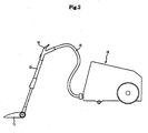
- a conventional vacuum cleaner includes a body 1 defining an outer appearance, a blower fan unit 2 positioned within the body 1 to generate suction force, and a dust collection unit 3 to filter foreign matter from air drawn into the body 1.
- the vacuum cleaner is operated in such a manner that suction force is generated by the blower fan unit 2 to draw foreign matter such as dust along with air into the body 1, and only the air is discharged to an outside of the body by filtering the foreign matter from the air via dust collection unit 3 positioned in the body 1, thereby cleaning a room.
- the blower fan unit 2 of the conventional vacuum cleaner includes a blower fan 2a to generate suction force while rotating, and a motor 2b to rotate the blower fan 2a.
- the blower fan 2a and the motor 2b are positioned to have a rotational axis disposed longitudinally in a front and rear direction such that air is drawn in from a front side, and is then discharged to a rear side. After being discharged to the rear side, the air is guided along a discharge flow path 6, passes through a discharged-air filter 5, and is then discharged to the outside of the body 1 via an air vent 4 positioned at a rear upper portion of the body 1.
- noise is generated due to various causes. Specifically, noise generated by rotation of the motor 2b, noise generated when air passes through the discharged-air filter 5 via the discharge flow path 6, and noise generated by friction between the air flowing at high speed within the discharge flow path 6 and a duct 7 defining the discharge flow path 6 are causes for the majority of the noise generated from the vacuum cleaner.
- the conventional vacuum cleaner has problems in that, since the length of the discharge flow path 6 from a discharge port 8 of the blower fan unit 2 to the air vent 4 is short, noise generated by rotation of the motor 2b is transferred to the outside of the body 1 without being sufficiently reduced, and in that, since the length from the discharged-air filter 5 to the air vent 4 is also short, the noise generated when air passes through the discharged-air filter 5 via the discharge flow path 6 is also transferred to the outside of the body 1 without being sufficiently reduced.
- DE-C-196 16156 discloses a vacuum cleaner with a lower housing part and an upper housing part forming a body.
- a dust collection chamber is provided in a front part of the vacuum cleaner and is used for filtering foreign material.
- a blower fan and a corresponding electric motor are provided and for discharging air, a corresponding air vent is also provided. This air vent is used for discharging air drawn into the housing of the vacuum cleaner.
- the discharged-air filter may be positioned at a location of the discharge flow path where the discharge flow path has the greatest cross-sectional area.
- the discharged-air filter may be positioned at a location of the discharge flow path where the discharge flow path has a greater cross-sectional area than that of the discharge port of the blower fan unit.
- the discharge port of the blower fan unit may have a greater area than that of the air vent.
- the discharge port of the blower fan unit may have an area of 7,000 mm 2 or more, and the air vent may have an area of 7,000 mm 2 or less.
- the door may be hinged at one side to the opening, while being hooked at the other side thereto.
- the dust collection unit may be a cylindrical cyclone device to separate the foreign matter via centrifugal force.
- the second flow path may be formed at both sides centered on the cyclone device.
- the discharge flow path may have a noise absorption material attached to an inner portion thereof.
- a vacuum cleaner according to a preferred embodiment of the invention includes a suction unit 11 to suck foreign matter together with air via suction force, and a body 10 to collect the foreign matter suctioned by the suction unit 11.
- the body 10 and the suction unit 11 are connected via a connection hose 12 and a connection pipe 13 such that the suction force generated from the body 10 is transferred to the suction unit 11 therethrough.
- the vacuum cleaner is further provided with a handle 14 between the connection hose 12 and the connection pipe 13 so as to be gripped by a user when using the vacuum cleaner.
- connection hose 12 is made of a stretchable corrugated pipe and the like.
- the connection hose 12 is connected at one end with the body 10, and at the other end with the handle 14 such that the suction unit 11 can be freely moved in a predetermined radius around the body 10.
- the connection pipe 13 has a predetermined length, and is connected at one end with the suction unit 11 while being connected at the other end with the handle 14 to allow the user to clean the floor using the vacuum cleaner while standing on the floor.
- the body 10 is connected at a front side with the connection hose 12 to allow air to flow thereto through the connection hose 12, and is formed at a rear upper portion with an air vent 15 through which, after having the foreign matter removed via a dust collection unit 20 in the body 10, the air is discharged to an outside of the body 10.
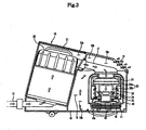
- the body 10 has an interior partitioned into a dust collection compartment 10a having the dust collection unit 20 positioned therein, a suction compartment 10b having a blower fan unit 30 and a discharge flow path 16 positioned therein, and a power source cord compartment 10c having a power source cord (not shown) positioned therein.
- the dust collection unit 20 is positioned in the dust collection compartment 10a to collect dust drawn into the dust collection compartment 10a via the connection hose 12.
- the dust collection unit 20 is implemented by a cyclone device which separates the foreign matter from the air drawn into the dust collection unit 20 using centrifugal force.
- the dust collection compartment 10a has a cover 21 hinged to an upper portion of the dust collection compartment 10a to allow the dust collection unit 20 to be detachably mounted to the dust collection compartment 10a.
- the blower fan unit 30 serves to generate suction force in the vacuum cleaner, and is positioned in the suction compartment 10b such that a rotational axis of the blower fan unit 30 is disposed up and down therein.
- the blower fan unit 30 includes a blower fan 31 to generate the suction force, and a motor 32 to rotate the blower fan 31.
- the blower fan unit 30 has an interior partitioned into a blowing part 30a having the blower fan 31 positioned therein, and a driving part 30b having the motor 32 positioned therein.
- a suction side of the blower fan unit 30 is communicated with a discharge side of the dust collection unit 20 via the connection pipe 17 to generate the suction force in the dust collection unit 20.
- the blower fan 31 of the blower fan unit 30 is constituted by a centrifugal fan which suctions air in an axial direction, and then discharges in a radial direction.
- the air discharged from the blowing fan 31 cools the motor 32 while passing through the driving part 30b, and is then discharged in the radial direction through a plurality of discharge outlets 34 formed on an outer periphery of a motor case 33 surrounding the motor 32.
- the air After being discharged through the discharge outlets 34 of the blower fan unit 30, the air flows along an inner flow path 41 defined within a case 40 surrounding the blower fan unit 30, and is discharged through a discharge port 42 formed at a lower portion of the blower fan unit 30. Then, the air is discharged through the air vent 15 via a discharge flow path 16.
- the discharge flow path 16 refers to a flow path of air from the discharge port 42 of the blower fan unit 30 to the air vent 15.
- a space defined between the dust collection unit 20 and the blower fan unit 30 constitutes a portion of the discharge flow path 16.
- the discharge flow path 16 is bent a number of times, and include a first flow path 16a which is defined from the discharge port 42 of the blower fan unit 30 to the space between the dust collection unit 30 and the blower fan unit 20, a second flow path 16b which extends from the first flow path 16a and is defined in the space between the dust collection unit 30 and the blower fan unit 20, and a third flow path 16c from the second flow path 16b to the air vent 15.
- the invention utilizes the space defined therebetween as a portion of the discharge flow path 16, and thus secures an enough length of the discharge flow path 16 to enable satisfactory reduction of noise generated from the motor 32 without increasing the size of the body 10.
- a discharged-air filter 18 is positioned in the discharge flow path 16 to filter the foreign matter which is not filtered by the dust collection unit 20.
- the discharged-air filter 18 is positioned in the first flow path 16a or the second flow path 16b.
- the discharged-air filter 18 is positioned in the first flow path 16a or the second flow path 16b having a relatively larger cross-sectional area, it is possible to secure a sufficient area of the discharged-air filter 18, thereby reducing pressure loss occurring when the air passes through the discharged-air filter 18.
- the first flow path 16a or the second flow path 16b has a greater cross-sectional area than that of the discharge port 42 of the blower fan unit 30, and the discharge port 42 of the blower fan unit 30 has a greater cross-sectional area than that of the air vent 15.
- the discharge port 42 of the blower fan unit 30 has an area of 7,000 mm 2 or more, and the air vent 15 has an area of 7,000 mm 2 or less.
- the cross-sectional area of the discharge flow path 16 gradually increases and then decreases from the discharge port 42 of the blower fan unit 30 to the air vent 15.
- the discharge flow path 16 has a noise absorption material attached to an inner portion thereof to absorb noise. That is, the discharge flow path 16 has the structure, which can expand, resonate, and absorb the noise as in a muffler of a vehicle, and thus significantly reduces the noise generated from the body 10.
- the second flow path 16b of the discharge flow path 16 is mainly formed at both sides centered on the dust collection unit 20 as shown in FIG. 4 .
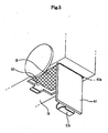
- the body 10 Since the discharged-air filter 18 is mainly positioned in the first flow path 16a or the second flow path 16b, the body 10 has an opening 50 which is formed in a bottom surface 19 to exchange the discharged-air filter therethrough, and opened and closed by a door 51, as shown in FIG. 5 .
- the door 51 is coupled at one side thereof to the opening 50 by a hinge 51 a, while being coupled at the other side thereto by a hook 51 b.
- the vacuum cleaner according to the invention has a sufficient length of the discharge flow path so that noise generated from the motor is sufficiently reduced as the air is discharged through the air vent after passing along the discharge flow path.
- the discharged-air filter is separated a predetermined distance from the air vent so that noise generated due to air passing through the discharged-air filter is sufficiently reduced.
Claims (12)
- Staubsauger, umfassend:einen Körper (10);eine Staubsammeleinheit (20), die in dem Körper (10) angeordnet ist, um Fremdkörper zu filtern;eine Windradgebläseeinheit (30), die ein Windradgebläse (31) und einen Motor (32) umfasst, um eine Saugkraft zu erzeugen;eine Luftöffnung (15), durch die Luft, die in den Körper (10) gesaugt wird, ausgegeben wird; undeinen Ausgabeströmungsweg (16), um die Luft, die durch einen Ausgabeanschluss (42) der Windradgebläseeinheit (30) ausgegeben wird, zu der Luftöffnung (15) zu leiten, wobei der Ausgabeströmungsweg (16) einen Zwischenraum umfasst, der zwischen der Staubsammeleinheit (20) und der Windradgebläseeinheit (30) angeordnet ist, wobeider Ausgabeströmungsweg (16) mehrmals gebogen ist und der Ausgabeströmungsweg umfasst:dadurch gekennzeichnet, dasseinen ersten Strömungsweg (16a), der von dem Ausgabeanschluss (42) der Windradgebläseeinheit (30) zu dem Zwischenraum ausgebildet ist, der sich zwischen der Staubsammeleinheit (20) und der Windradgebläseeinheit (30) befindet;einen zweiten Strömungsweg (16b), der sich von dem ersten Strömungsweg (16a) erstreckt und in dem Zwischenraum zwischen der Staubsammeleinheit (20) und der Windradgebläseeinheit (30) ausgebildet ist, undeinen dritten Strömungsweg (16c) von dem zweiten Strömungsweg (16b) zu der Luftöffnung,
ein Ausgabeluftfilter (18) in dem ersten Strömungsweg (16a) oder dem zweiten Strömungsweg (16b) angeordnet ist, um die Fremdkörper in der Luft zu filtern, die durch den Ausgabeanschluss (42) der Windradgebläseeinheit ausgegeben wird, und der Körper (10) eine Öffnung (50) aufweist, die in einer Unterseite (19) ausgebildet ist, um den Ausgabeluftfilter (18) durch diese zu wechseln, und mit einer Tür (51) geöffnet und geschlossen wird. - Staubsauger nach Anspruch 1, dadurch gekennzeichnet, dass der Ausgabeluftfilter (18) an einer Stelle des Ausgabeströmungsweges (16) angeordnet ist, an der der Ausgabeströmungsweg die größte Querschnittsfläche hat.
- Staubsauger nach Anspruch 1, dadurch gekennzeichnet, dass der Ausgabeluftfilter (18) an einer Stelle des Ausgabeströmungsweges (16) angeordnet ist, an der der Ausgabeströmungsweg eine größere Querschnittsfläche als jene des Ausgabeanschlusses (42) der Windradgebläseeinheit (30) hat.
- Staubsauger nach Anspruch 3, dadurch gekennzeichnet, dass der Ausgabeanschluss (42) der Windradgebläseeinheit (30) eine größere Fläche hat als jene der Luftöffnung (15).
- Staubsauger nach Anspruch 4, dadurch gekennzeichnet, dass der Ausgabeanschluss (42) der Windradgebläseeinheit (30) eine Fläche von wenigstens 7.000 mm2 und die Luftöffnung eine Fläche von höchstens 7.000 mm2 hat.
- Staubsauger nach Anspruch 1, dadurch gekennzeichnet, dass die Tür (51) an einer Seite der Öffnung (50) angeschlagen ist, während sie an der anderen Seite derselben verriegelt wird.
- Staubsauger nach Anspruch 1, dadurch gekennzeichnet, dass die Staubsammeleinheit (20) eine zylindrische Zyklonvorrichtung ist, um die Fremdkörper durch Zentrifugalkraft zu trennen.
- Staubsauger nach Anspruch 6, dadurch gekennzeichnet, dass der zweite Strömungsweg (16b) auf beiden Seiten zentriert an der Zyklonvorrichtung ausgebildet ist.
- Staubsauger nach Anspruch 1, dadurch gekennzeichnet, dass der Ausgabeströmungsweg (16) ein Schallabsorptionsmaterial hat, das an einem Innenabschnitt desselben angebracht ist.
- Verfahren zum Reduzieren des Geräusches, das von einem Staubsauger erzeugt wird, umfassend:Saugen von Luft, die Fremdkörper enthält, zu einem Staubsammelabteil (10a), in dem sich eine Staubsammeleinheit (20) befindet;Weiterleiten und Filtern der Luft von der Staubsammeleinheit (20) mit Hilfe eines Saugabteils (10b), in dem sich eine Windradgebläseeinheit (30) und ein Ausgabeströmungsweg (16) befinden,wobei ein Zwischenraum zwischen der Staubsammeleinheit (20) und der Windradgebläseeinheit (30) den Ausgabeströmungsweg (16) bildet, unddie Windradgebläseeinheit (30) ein Windradgebläse (31) umfasst, das einen Gebläseteil (30a), um eine Saugkraft zu erzeugen, und einen Motor (32) hat, der über einen Antriebsteil (30b) verfügt, um das Windradgebläse (31) zu drehen, das darin angeordnet ist;Erzeugen der Saugkraft, um die Luft aus dem Windradgebläse (31) auszugeben, während der Motor gekühlt wird, wenn die Luft und die Fremdkörper den Antriebsteil (30b) durchlaufen;Ausgeben der Luft durch eine Vielzahl von Ausgabeauslässen (34), die in einem Außenumfang eines Motorgehäuses (40) ausgebildet sind, das den Motor (32) umgibt;Leiten der Luft entlang eines inneren Leitungsweges (41), der in einem Gehäuse (40) ausgebildet ist, das die Windradgebläseeinheit (30) umgibt; undAusgeben der Luft durch einen Ausgabeanschluss (42), der an einem unteren Abschnitt der Windradgebläseeinheit (30) ausgebildet ist, über den Ausgabeleitungsweg (16), der den Ausgabeanschluss (42) der Windradgebläseeinheit mit einer Luftöffnung (15) verbindet, wobei das Leiten der Luft durch den Ausgabeströmungsweg umfasst:dadurch gekennzeichnet, dassLeiten der Luft durch einen ersten Strömungsweg (16a), der von dem Ausgabeanschluss (42) der Windradgebläseeinheit (30) zu dem Zwischenraum zwischen der Staubsammeleinheit (20) und der Windradgebläseeinheit (30) ausgebildet ist,Leiten der Luft durch einen zweiten Strömungsweg (16b), der sich von dem ersten Strömungsweg (16a) erstreckt und in dem Zwischenraum zwischen der Staubsammeleinheit (20) und der Windradgebläseeinheit (30) ausgebildet ist;Leiten der Luft durch einen dritten Strömungsweg (16c) von dem zweiten Strömungsweg (16b); undAusgeben der Luft durch die Luftöffnung (15),
das Verfahren weiterhin das Positionieren eines Ausgabeluftfilters (18) in dem ersten Strömungsweg (16a) oder dem zweiten Strömungsweg (16b), um die Luft zu filtern, und das Wechseln des Ausgabeluftfilters (18) durch eine Öffnung (50) umfasst, die in einer Unterseite (19) eines Körpers (10) des Staubsaugers ausgebildet ist, wobei die Öffnung (50) durch eine Tür (51) geöffnet und geschlossen wird. - Verfahren nach Anspruch 10, bei dem sich während des Leitens und Filterns die Luft durch den Ausgabeströmungsweg nicht linear bewegt.
- Verfahren nach Anspruch 10, bei dem sich während des Leitens und Filterns die Luft durch den Ausgabeströmungsweg nicht linear bewegt.
Applications Claiming Priority (1)
| Application Number | Priority Date | Filing Date | Title |
|---|---|---|---|
| KR1020050131050A KR101353311B1 (ko) | 2005-12-27 | 2005-12-27 | 진공청소기 |
Publications (3)
| Publication Number | Publication Date |
|---|---|
| EP1803382A2 EP1803382A2 (de) | 2007-07-04 |
| EP1803382A3 EP1803382A3 (de) | 2008-09-03 |
| EP1803382B1 true EP1803382B1 (de) | 2013-03-20 |
Family
ID=37832041
Family Applications (1)
| Application Number | Title | Priority Date | Filing Date |
|---|---|---|---|
| EP06014947A Expired - Fee Related EP1803382B1 (de) | 2005-12-27 | 2006-07-18 | Staubsauger und Methode zur Verminderung des damit erzeugten Lärms |
Country Status (5)
| Country | Link |
|---|---|
| US (1) | US7774898B2 (de) |
| EP (1) | EP1803382B1 (de) |
| KR (1) | KR101353311B1 (de) |
| CN (1) | CN1989890B (de) |
| RU (1) | RU2323674C1 (de) |
Cited By (1)
| Publication number | Priority date | Publication date | Assignee | Title |
|---|---|---|---|---|
| EP3449790B1 (de) * | 2017-09-05 | 2022-03-23 | Nidec Corporation | Motormodul und staubsauger |
Families Citing this family (25)
| Publication number | Priority date | Publication date | Assignee | Title |
|---|---|---|---|---|
| SE533268C2 (sv) | 2008-12-17 | 2010-08-03 | Electrolux Ab | Dammsugare |
| CA2658025A1 (en) * | 2009-03-11 | 2010-09-11 | G.B.D. Corp. | Portable surface cleaning apparatus |
| US9433332B2 (en) | 2013-02-27 | 2016-09-06 | Omachron Intellectual Property Inc. | Surface cleaning apparatus |
| US9265395B2 (en) | 2010-03-12 | 2016-02-23 | Omachron Intellectual Property Inc. | Surface cleaning apparatus |
| JP2012055499A (ja) * | 2010-09-09 | 2012-03-22 | Panasonic Corp | 電気掃除機 |
| CN102894931B (zh) * | 2011-07-29 | 2016-03-23 | 莱克电气股份有限公司 | 具有改良型电机罩的吸尘器 |
| FR2979814B1 (fr) * | 2011-09-12 | 2013-08-23 | Seb Sa | Aspirateur comportant un silencieux et un diffuseur d'air |
| CN102309285A (zh) * | 2011-09-14 | 2012-01-11 | 江苏美的春花电器股份有限公司 | 一种静音吸尘器 |
| KR101397054B1 (ko) * | 2012-08-31 | 2014-05-20 | 엘지전자 주식회사 | 진공청소기 |
| US9591958B2 (en) | 2013-02-27 | 2017-03-14 | Omachron Intellectual Property Inc. | Surface cleaning apparatus |
| US9320401B2 (en) | 2013-02-27 | 2016-04-26 | Omachron Intellectual Property Inc. | Surface cleaning apparatus |
| GB2513662B (en) * | 2013-05-03 | 2015-10-21 | Dyson Technology Ltd | Compressor flow path |
| EP2870905B1 (de) * | 2013-11-11 | 2019-01-02 | NELA razvojni center d.o.o. Podruznica OTOKI | System zum Reduzieren von Staubsaugerlärm und -schwingungen |
| EP3207845B1 (de) * | 2014-10-13 | 2019-09-04 | Jiangsu Midea Cleaning Appliances Co., Ltd. | Luftkanalstruktur und oberflächenreinigungsvorrichtung damit |
| KR101509738B1 (ko) * | 2014-10-27 | 2015-04-14 | 주식회사코네트인더스트리 | 진공청소기용 더스트컨테이너 조립체 |
| KR101684796B1 (ko) * | 2015-08-18 | 2016-12-08 | 엘지전자 주식회사 | 흡입 유닛 |
| EP3383241B1 (de) * | 2015-12-04 | 2022-05-18 | Aktiebolaget Electrolux | Vakuumreiniger |
| FR3046046B1 (fr) | 2015-12-23 | 2017-12-22 | Seb Sa | Geometrie d'un circuit aeraulique pour un aspirateur a main |
| JP2018064849A (ja) * | 2016-10-21 | 2018-04-26 | 日本電産株式会社 | モータモジュールおよび掃除機 |
| US11478116B2 (en) | 2018-01-15 | 2022-10-25 | Omachron Intellectual Property Inc | Surface cleaning apparatus |
| JP7085424B2 (ja) * | 2018-07-04 | 2022-06-16 | シャープ株式会社 | 電気掃除機 |
| US11013384B2 (en) | 2018-08-13 | 2021-05-25 | Omachron Intellectual Property Inc. | Cyclonic air treatment member and surface cleaning apparatus including the same |
| US11192122B2 (en) | 2018-08-13 | 2021-12-07 | Omachron Intellectual Property Inc. | Cyclonic air treatment member and surface cleaning apparatus including the same |
| US11006799B2 (en) | 2018-08-13 | 2021-05-18 | Omachron Intellectual Property Inc. | Cyclonic air treatment member and surface cleaning apparatus including the same |
| RU193170U1 (ru) * | 2019-08-08 | 2019-10-15 | Максим Юрьевич Минаков | Вытяжка для удаления пыли в салонах красоты с ногтевым сервисом |
Family Cites Families (20)
| Publication number | Priority date | Publication date | Assignee | Title |
|---|---|---|---|---|
| US3866263A (en) * | 1973-04-17 | 1975-02-18 | Hoover Co | Cleaner with auxiliary air flow |
| DE9006336U1 (de) | 1990-06-05 | 1991-10-02 | Siemens Ag, 8000 Muenchen, De | |
| KR930001867A (ko) * | 1991-07-26 | 1993-02-22 | 배순훈 | 저소음 진공청소기 |
| KR930008363B1 (ko) * | 1991-08-12 | 1993-08-31 | 대우전자 주식회사 | 저소음 진공청소기 |
| KR0138969B1 (ko) * | 1993-09-15 | 1998-05-15 | 김광호 | 진공청소기 |
| KR970009718A (ko) * | 1995-08-31 | 1997-03-27 | 배순훈 | 진공 청소기의 배기 유로를 길게한 흡음방 |
| DE19616156C1 (de) | 1996-04-23 | 1997-10-02 | Fakir Werk Gmbh & Co | Staubsauger |
| JP3654330B2 (ja) * | 1997-10-27 | 2005-06-02 | 株式会社大宇エレクトロニクス | 低騒音真空掃除機 |
| US6735817B2 (en) * | 1998-01-09 | 2004-05-18 | Royal Appliance Mfg. Co. | Upright vacuum cleaner with cyclonic air flow |
| RU2150226C1 (ru) | 1998-04-21 | 2000-06-10 | Акционерное общество "Нижегородский машиностроительный завод" | Пылесос |
| CN2408819Y (zh) * | 2000-02-23 | 2000-12-06 | 泰怡凯电器(苏州)有限公司 | 旋风式真空吸尘器 |
| KR100357516B1 (ko) * | 2000-06-30 | 2002-10-18 | 삼성광주전자 주식회사 | 배기환류 청소기 |
| KR100389289B1 (ko) * | 2000-09-22 | 2003-06-27 | 주식회사 대우일렉트로닉스 | 진공청소기 |
| US6532621B2 (en) * | 2001-01-12 | 2003-03-18 | Royal Appliance Mfg. Co. | Vacuum cleaner with noise suppression features |
| JP3635657B2 (ja) * | 2001-01-22 | 2005-04-06 | ツインバード工業株式会社 | サイクロン式掃除機 |
| CA2332195A1 (en) * | 2001-01-24 | 2002-07-24 | Alexandre Plomteux | Quiet central vacuum power unit |
| GB0203147D0 (en) * | 2002-02-11 | 2002-03-27 | Dyson Ltd | An exhaust assembly |
| KR100500848B1 (ko) * | 2003-07-07 | 2005-07-12 | 삼성광주전자 주식회사 | 진공청소기용 모터 조립체 및 이를 구비하는 진공청소기 |
| KR100555205B1 (ko) | 2003-12-31 | 2006-03-03 | 삼성광주전자 주식회사 | 진공청소기 |
| KR100725515B1 (ko) | 2005-12-15 | 2007-06-08 | 삼성광주전자 주식회사 | 모터 소음저감구조를 갖는 진공청소기 |
-
2005
- 2005-12-27 KR KR1020050131050A patent/KR101353311B1/ko not_active IP Right Cessation
-
2006
- 2006-07-12 US US11/484,703 patent/US7774898B2/en not_active Expired - Fee Related
- 2006-07-18 EP EP06014947A patent/EP1803382B1/de not_active Expired - Fee Related
- 2006-07-27 RU RU2006127372/11A patent/RU2323674C1/ru not_active IP Right Cessation
- 2006-07-28 CN CN2006101087101A patent/CN1989890B/zh not_active Expired - Fee Related
Cited By (1)
| Publication number | Priority date | Publication date | Assignee | Title |
|---|---|---|---|---|
| EP3449790B1 (de) * | 2017-09-05 | 2022-03-23 | Nidec Corporation | Motormodul und staubsauger |
Also Published As
| Publication number | Publication date |
|---|---|
| CN1989890A (zh) | 2007-07-04 |
| CN1989890B (zh) | 2011-01-19 |
| RU2323674C1 (ru) | 2008-05-10 |
| US20070143952A1 (en) | 2007-06-28 |
| EP1803382A2 (de) | 2007-07-04 |
| EP1803382A3 (de) | 2008-09-03 |
| KR20070068941A (ko) | 2007-07-02 |
| RU2006127372A (ru) | 2008-02-10 |
| KR101353311B1 (ko) | 2014-01-24 |
| US7774898B2 (en) | 2010-08-17 |
Similar Documents
| Publication | Publication Date | Title |
|---|---|---|
| EP1803382B1 (de) | Staubsauger und Methode zur Verminderung des damit erzeugten Lärms | |
| EP3209175B1 (de) | Handstaubsauger | |
| EP1803381B1 (de) | Staubsager | |
| KR101892653B1 (ko) | 전기청소기 | |
| KR101821908B1 (ko) | 전기청소기 | |
| EP1857032B1 (de) | Staubsauger mit primärer und sekundären Zykloneinheiten | |
| EP1074212B1 (de) | Staubsauger | |
| US7556661B2 (en) | Dust collection unit and vacuum cleaner with same | |
| CN110074718B (zh) | 手持式吸尘器 | |
| WO2014050614A1 (ja) | 電気掃除機 | |
| JP4823875B2 (ja) | 電気掃除機の吸込口体 | |
| KR20060122521A (ko) | 진공청소기 | |
| JP4937984B2 (ja) | 電気掃除機 | |
| US20230022866A1 (en) | Dust collector and cleaner having the same | |
| JP4078154B2 (ja) | 電気掃除機 | |
| CN111588303B (zh) | 吸尘器 | |
| CN107212809B (zh) | 垃圾桶式吸尘器 | |
| EP2789282A1 (de) | Elektrischer staubsauger | |
| AU2006249292B2 (en) | Vacuum cleaner | |
| KR200192862Y1 (ko) | 업라이트 진공청소기의 배기부구조 | |
| KR100677878B1 (ko) | 진공청소기 | |
| JP2010094246A (ja) | 電気掃除機の吸込口体 | |
| KR20070048875A (ko) | 진공 청소기 | |
| KR101256102B1 (ko) | 진공청소기 | |
| KR100577277B1 (ko) | 진공청소기 |
Legal Events
| Date | Code | Title | Description |
|---|---|---|---|
| PUAI | Public reference made under article 153(3) epc to a published international application that has entered the european phase |
Free format text: ORIGINAL CODE: 0009012 |
|
| AK | Designated contracting states |
Kind code of ref document: A2 Designated state(s): AT BE BG CH CY CZ DE DK EE ES FI FR GB GR HU IE IS IT LI LT LU LV MC NL PL PT RO SE SI SK TR |
|
| AX | Request for extension of the european patent |
Extension state: AL BA HR MK YU |
|
| PUAL | Search report despatched |
Free format text: ORIGINAL CODE: 0009013 |
|
| AK | Designated contracting states |
Kind code of ref document: A3 Designated state(s): AT BE BG CH CY CZ DE DK EE ES FI FR GB GR HU IE IS IT LI LT LU LV MC NL PL PT RO SE SI SK TR |
|
| AX | Request for extension of the european patent |
Extension state: AL BA HR MK RS |
|
| 17P | Request for examination filed |
Effective date: 20090216 |
|
| 17Q | First examination report despatched |
Effective date: 20090313 |
|
| AKX | Designation fees paid |
Designated state(s): DE FR GB |
|
| GRAP | Despatch of communication of intention to grant a patent |
Free format text: ORIGINAL CODE: EPIDOSNIGR1 |
|
| RAP1 | Party data changed (applicant data changed or rights of an application transferred) |
Owner name: SAMSUNG ELECTRONICS CO., LTD. |
|
| GRAS | Grant fee paid |
Free format text: ORIGINAL CODE: EPIDOSNIGR3 |
|
| GRAA | (expected) grant |
Free format text: ORIGINAL CODE: 0009210 |
|
| AK | Designated contracting states |
Kind code of ref document: B1 Designated state(s): DE FR GB |
|
| REG | Reference to a national code |
Ref country code: GB Ref legal event code: FG4D |
|
| REG | Reference to a national code |
Ref country code: DE Ref legal event code: R096 Ref document number: 602006035139 Country of ref document: DE Effective date: 20130516 |
|
| PLBE | No opposition filed within time limit |
Free format text: ORIGINAL CODE: 0009261 |
|
| STAA | Information on the status of an ep patent application or granted ep patent |
Free format text: STATUS: NO OPPOSITION FILED WITHIN TIME LIMIT |
|
| 26N | No opposition filed |
Effective date: 20140102 |
|
| REG | Reference to a national code |
Ref country code: DE Ref legal event code: R097 Ref document number: 602006035139 Country of ref document: DE Effective date: 20140102 |
|
| REG | Reference to a national code |
Ref country code: DE Ref legal event code: R082 Ref document number: 602006035139 Country of ref document: DE Representative=s name: PFENNING, MEINIG & PARTNER MBB PATENTANWAELTE, DE |
|
| REG | Reference to a national code |
Ref country code: FR Ref legal event code: PLFP Year of fee payment: 11 |
|
| REG | Reference to a national code |
Ref country code: FR Ref legal event code: PLFP Year of fee payment: 12 |
|
| REG | Reference to a national code |
Ref country code: FR Ref legal event code: PLFP Year of fee payment: 13 |
|
| PGFP | Annual fee paid to national office [announced via postgrant information from national office to epo] |
Ref country code: FR Payment date: 20180622 Year of fee payment: 13 |
|
| PGFP | Annual fee paid to national office [announced via postgrant information from national office to epo] |
Ref country code: GB Payment date: 20180621 Year of fee payment: 13 Ref country code: DE Payment date: 20180620 Year of fee payment: 13 |
|
| REG | Reference to a national code |
Ref country code: DE Ref legal event code: R119 Ref document number: 602006035139 Country of ref document: DE |
|
| GBPC | Gb: european patent ceased through non-payment of renewal fee |
Effective date: 20190718 |
|
| PG25 | Lapsed in a contracting state [announced via postgrant information from national office to epo] |
Ref country code: GB Free format text: LAPSE BECAUSE OF NON-PAYMENT OF DUE FEES Effective date: 20190718 Ref country code: DE Free format text: LAPSE BECAUSE OF NON-PAYMENT OF DUE FEES Effective date: 20200201 |
|
| PG25 | Lapsed in a contracting state [announced via postgrant information from national office to epo] |
Ref country code: FR Free format text: LAPSE BECAUSE OF NON-PAYMENT OF DUE FEES Effective date: 20190731 |