EP1801547B1 - Verfahren und Vorrichtung zur Bestimmung der Position eines ersten Teils relativ zu einem zweiten - Google Patents
Verfahren und Vorrichtung zur Bestimmung der Position eines ersten Teils relativ zu einem zweiten Download PDFInfo
- Publication number
- EP1801547B1 EP1801547B1 EP06077188A EP06077188A EP1801547B1 EP 1801547 B1 EP1801547 B1 EP 1801547B1 EP 06077188 A EP06077188 A EP 06077188A EP 06077188 A EP06077188 A EP 06077188A EP 1801547 B1 EP1801547 B1 EP 1801547B1
- Authority
- EP
- European Patent Office
- Prior art keywords
- optical
- diffractive
- code
- signal
- support
- Prior art date
- Legal status (The legal status is an assumption and is not a legal conclusion. Google has not performed a legal analysis and makes no representation as to the accuracy of the status listed.)
- Not-in-force
Links
- 238000000034 method Methods 0.000 title claims abstract description 45
- 230000003287 optical effect Effects 0.000 claims abstract description 124
- 230000033001 locomotion Effects 0.000 claims abstract description 13
- 230000005540 biological transmission Effects 0.000 claims abstract description 11
- 238000001514 detection method Methods 0.000 claims description 30
- 238000004422 calculation algorithm Methods 0.000 claims description 11
- 125000004122 cyclic group Chemical group 0.000 claims description 6
- 230000001360 synchronised effect Effects 0.000 claims description 2
- 230000000295 complement effect Effects 0.000 description 10
- 239000000463 material Substances 0.000 description 9
- 230000006870 function Effects 0.000 description 8
- 238000012545 processing Methods 0.000 description 8
- 230000008901 benefit Effects 0.000 description 7
- 239000000470 constituent Substances 0.000 description 6
- 230000001747 exhibiting effect Effects 0.000 description 6
- 238000004519 manufacturing process Methods 0.000 description 5
- 238000004458 analytical method Methods 0.000 description 4
- 230000008859 change Effects 0.000 description 4
- 238000006073 displacement reaction Methods 0.000 description 4
- 238000009826 distribution Methods 0.000 description 4
- 238000005259 measurement Methods 0.000 description 4
- 238000004364 calculation method Methods 0.000 description 3
- 238000012937 correction Methods 0.000 description 3
- 238000011161 development Methods 0.000 description 3
- 229920003229 poly(methyl methacrylate) Polymers 0.000 description 3
- 239000004926 polymethyl methacrylate Substances 0.000 description 3
- 230000009471 action Effects 0.000 description 2
- 239000000853 adhesive Substances 0.000 description 2
- 230000007547 defect Effects 0.000 description 2
- 238000005516 engineering process Methods 0.000 description 2
- 239000013307 optical fiber Substances 0.000 description 2
- 230000000737 periodic effect Effects 0.000 description 2
- 239000004417 polycarbonate Substances 0.000 description 2
- 229920000515 polycarbonate Polymers 0.000 description 2
- 230000000717 retained effect Effects 0.000 description 2
- 238000005070 sampling Methods 0.000 description 2
- 230000007704 transition Effects 0.000 description 2
- 238000007514 turning Methods 0.000 description 2
- 230000005856 abnormality Effects 0.000 description 1
- 238000009825 accumulation Methods 0.000 description 1
- 230000003044 adaptive effect Effects 0.000 description 1
- 238000004378 air conditioning Methods 0.000 description 1
- 230000002547 anomalous effect Effects 0.000 description 1
- 230000003466 anti-cipated effect Effects 0.000 description 1
- 238000013459 approach Methods 0.000 description 1
- 238000003491 array Methods 0.000 description 1
- 201000009310 astigmatism Diseases 0.000 description 1
- 230000009286 beneficial effect Effects 0.000 description 1
- 230000015556 catabolic process Effects 0.000 description 1
- 238000006243 chemical reaction Methods 0.000 description 1
- 230000001427 coherent effect Effects 0.000 description 1
- 230000005494 condensation Effects 0.000 description 1
- 238000009833 condensation Methods 0.000 description 1
- 238000011109 contamination Methods 0.000 description 1
- 238000006731 degradation reaction Methods 0.000 description 1
- 230000006866 deterioration Effects 0.000 description 1
- 230000001627 detrimental effect Effects 0.000 description 1
- 230000000694 effects Effects 0.000 description 1
- 239000011521 glass Substances 0.000 description 1
- 238000005286 illumination Methods 0.000 description 1
- 230000010365 information processing Effects 0.000 description 1
- 238000003754 machining Methods 0.000 description 1
- 239000011159 matrix material Substances 0.000 description 1
- 238000001393 microlithography Methods 0.000 description 1
- 238000005457 optimization Methods 0.000 description 1
- 239000011368 organic material Substances 0.000 description 1
- 230000003071 parasitic effect Effects 0.000 description 1
- 230000002093 peripheral effect Effects 0.000 description 1
- 239000010453 quartz Substances 0.000 description 1
- 230000009467 reduction Effects 0.000 description 1
- 238000004092 self-diagnosis Methods 0.000 description 1
- 229910052710 silicon Inorganic materials 0.000 description 1
- 239000010703 silicon Substances 0.000 description 1
- VYPSYNLAJGMNEJ-UHFFFAOYSA-N silicon dioxide Inorganic materials O=[Si]=O VYPSYNLAJGMNEJ-UHFFFAOYSA-N 0.000 description 1
- 229920002994 synthetic fiber Polymers 0.000 description 1
- 230000009466 transformation Effects 0.000 description 1
- 230000001052 transient effect Effects 0.000 description 1
- 239000012780 transparent material Substances 0.000 description 1
Images







Classifications
-
- G—PHYSICS
- G01—MEASURING; TESTING
- G01D—MEASURING NOT SPECIALLY ADAPTED FOR A SPECIFIC VARIABLE; ARRANGEMENTS FOR MEASURING TWO OR MORE VARIABLES NOT COVERED IN A SINGLE OTHER SUBCLASS; TARIFF METERING APPARATUS; MEASURING OR TESTING NOT OTHERWISE PROVIDED FOR
- G01D5/00—Mechanical means for transferring the output of a sensing member; Means for converting the output of a sensing member to another variable where the form or nature of the sensing member does not constrain the means for converting; Transducers not specially adapted for a specific variable
- G01D5/26—Mechanical means for transferring the output of a sensing member; Means for converting the output of a sensing member to another variable where the form or nature of the sensing member does not constrain the means for converting; Transducers not specially adapted for a specific variable characterised by optical transfer means, i.e. using infrared, visible, or ultraviolet light
- G01D5/32—Mechanical means for transferring the output of a sensing member; Means for converting the output of a sensing member to another variable where the form or nature of the sensing member does not constrain the means for converting; Transducers not specially adapted for a specific variable characterised by optical transfer means, i.e. using infrared, visible, or ultraviolet light with attenuation or whole or partial obturation of beams of light
- G01D5/34—Mechanical means for transferring the output of a sensing member; Means for converting the output of a sensing member to another variable where the form or nature of the sensing member does not constrain the means for converting; Transducers not specially adapted for a specific variable characterised by optical transfer means, i.e. using infrared, visible, or ultraviolet light with attenuation or whole or partial obturation of beams of light the beams of light being detected by photocells
- G01D5/347—Mechanical means for transferring the output of a sensing member; Means for converting the output of a sensing member to another variable where the form or nature of the sensing member does not constrain the means for converting; Transducers not specially adapted for a specific variable characterised by optical transfer means, i.e. using infrared, visible, or ultraviolet light with attenuation or whole or partial obturation of beams of light the beams of light being detected by photocells using displacement encoding scales
Definitions
- the present invention relates to the general technical field of systems or devices allowing a relative movement between two components to be determined and measured, for example a displacement between a mobile part and a fixed part.
- EP-A-0512864 discloses a method for sensing the relative position of two members by scanning an optical beam over an encoded pattern on one member and by using a read head secure to the other member.
- EP-A-0729013 discloses displacement detection using a light source for illuminating a phase type diffraction grating, generating interference fringes, and generating a periodic signal from the received light.
- the present invention which relates to a method for determining the position of one of two moving components relatively to each other, consisting of:
- Diffractive optical coding further has advantages which are also expressed in the devices for applying the method, and which will be mentioned in more detail in the following text.
- the optical signal may be defined by the first diffraction order, the complementary signals in the same diffraction order being however retained in order to maintain the intensities of the detected light spots substantially constant. Interpretation errors are thereby avoided, related to a non-constant intensity of the spots to be detected and to be analyzed. Uniformization of the diffracted energy resulting from this facilitates the reading of the position which consequently is more reliable. A portion of the diffractive portion is read, and the complementary portion in the same diffraction order is not read, but used for counter-balancing the excess energy in order to uniformize the intensity.
- the conjugate order corresponding to the first diffraction order may however also be read and compared with the latter. With this, it is possible to carry out a check of the optical code obtained by reading the first diffraction order, as there is redundancy between both pieces of information.
- diffraction orders may however be used, for specifying, completing or checking the read-out of the optical signals.
- the information that is indicative of the quality of the signal may include error detecting and correcting codes such as parity codes, information facilitating checksum operations, and information facilitating polynomial redundancy checks.
- error detecting and correcting codes such as parity codes, information facilitating checksum operations, and information facilitating polynomial redundancy checks.
- parity (even or odd) codes enable the counting of the quantity of "ones" in a word, and a parity code is indicative of whether there are an even or odd number of "ones.”
- the receiving system may count the number of ones and compare the resulting count to the parity bit. In such a system, a disagreement may indicate an error and thus the system may assess the signal as unreliable (i.e., exhibiting poor quality). It should be noted that this method can detect single-bit errors and some multiple bit errors, but may be unable to correct the signal or otherwise improve its quality without additional means for doing so.
- the information that is indicative of the quality of the signal may also include information facilitating checksum operations.
- Checksums can be used on groups of data words wherein the sum of the data words is calculated and stored with the data.
- the receiving system calculates the same checksum and compares it with the received checksum.
- a disagreement may indicate an error and thus the system may assess the signal as unreliable (i.e., exhibiting poor quality).
- the information that is indicative of the quality of the signal may also include information facilitating cyclic redundancy checks using polynomials.
- complex polynomials may be utilized that can not only detect, but in some cases correct, single- or multiple-bit errors.
- the position corresponding to the last detection is stored. If need be, this allows anomalous movements to be detected, for example occurring during failure or deterioration of a mechanical part involved in the movement or in the determination of the position.
- optical code formed by each optical signal in the case in point appears as optical structures, on the base of which bits 0 and 1 of an electronic code are generated by means for detecting and reading said structures.
- Such an optical signal is extremely interesting as it is insensitive to vibrations, offsets (for example, it is translationally invariant with a Fourier diffractive support).
- each detected and read signal is submitted to an algorithm for calculating the position of the diffractive support relatively to the beam.
- the algorithm changes according to the relative displacement velocity.
- each detected and read optical code is compared with electronic codes stored in a memory table and which allow the position of the diffractive support to be determined on a one-to-one basis.
- Each code in fact corresponds to a unique position. It then needs to be identified, i.e., each code needs to be delimited in practice.
- the diffractive optical code may include at least one starting optical structure and at least one end optical structure delimiting the read-out area of the optical signal corresponding to a determined position of the diffractive support relatively to the beam.
- each optical code corresponding to a position of the diffractive support may include at least one optical synchronization structure, the detection of which allows the triggering of the read-out phase for the optical signal integrating the code of a position of the diffractive support relatively to the beam. This phase is then only carried out when the delimitation of the code is confirmed by the optical synchronization signal.
- a method includes the step of assessing the quality of the optical signal and/or of the position information interpreted from the optical signal. In another exemplary embodiment, a method includes the further step of correcting the position information to create a position signal having improved reliability.
- a system employing the described method includes means for assessing the quality of the optical signal and/or of the position information interpreted from the optical signal.
- a system employing the described method includes means for correcting the position information to create a position signal having improved reliability.
- each optical code corresponding to an identifiable position may finally include at least one optical calibration structure used for the purpose of diagnosing proper read-out operation.
- Said optical structures in fact consist of at least one light spot, the intensity of which may be measured.
- the analysis of these optical structures and of the signal which they form allows the system to conclude as to whether an adequate read-out is possible or not.
- the light spot forming the optical structure may assume different, more or less complex shapes.
- the codes defining the position of a component relatively to the other comply, in the order of their succession, with the GRAY code.
- the change of a single light spot at a known location therefore provides considerable simplification of the positioning analysis.
- the changes in intensity of at least one of the optical structures forming the optical signals may further be coded by an analog/digital converter, authorizing a binary or grey-level read-out with which the resolution of the measurement may be further refined.
- the light source may be pulsed according to a frequency controlled by the velocity of the moving component, the read-out being then synchronized with the generation of the light beam(s).
- the use of an optical synchronization signal may be omitted.
- the method reported above may be applied to any type of relative motion, and notably to relative rotation of two components. Under this assumption, it consists of determining the angular position of one of the components relatively to the other.
- the accuracy of the measurement depends on dimensional, manufacturing considerations, and also obviously on the desired definition for the signal: according to one possibility, the number of optical spots or structures used for coding the angular position, is at least equal to 12 to provide an angular resolution less than 0.1° and an accuracy of the same order of magnitude.
- the 4,096 possibilities provided by 12 bits actually allow a resolution of this order.
- a diffractive support including mounting means on a first component in relative motion with respect to a second component, and provided with at least one diffractive track, either continuous or not, said diffraction track having means for diffracting by reflection and/or by transmission, the light beam emitted by at least one light source, fixed with respect to the second component.
- the diffraction of the light rays may be obtained via different routes.
- the diffractive track may for example have an etched relief in the constituent material of the diffractive support, capable of diffracting the incident beam(s) and of generating an optical signal, the reading of which allows the position of the first component relatively to the second component to be identified, by identifying the code formed by the signal.
- the diffractive track may be obtained by modulating the transparence of the support, for example by applying an opaque material onto certain locations on a transparent support, to obtain the same result.
- the diffractive track may also be obtained by modulating the refractive index or even by a combining the mentioned solutions.
- modulation of the reliefs or of the opaque material the geometry and the distribution of which are calculated by a computer, generates a particular diffracted optical signal under the action of at least one light beam, said signal forming an optical code consisting of optical structures defining a unique position of the support at any time.
- the diffractive support may thus be made with known materials, with large reproducibility and without altering the accuracy and/or the resolution of the determination of each position. Large importance is attached to the selection of these materials, which preferably should be inexpensive and easy to machine.
- these materials may be polycarbonate, PMMA, and more generally all optically adequate materials.
- each track is divided into areas with an individualized diffractive structure generating a code corresponding to a unique position of the support, each area including a plurality of elementary shapes with a parallelogrammic aspect, positioned as a periodic or aperiodic grid.
- the diffractive support may for example include :
- the disk may include three diffractive tracks, the first one being used for defining the optical code, the second one being used for defining a synchronization signal and the third one being used for defining a calibration signal.
- each track is then divided into angular sectors with equal surfaces, delimiting said individualized diffractive structures.
- the angular sectors may have dimensions of the order of 10 ⁇ m to 100 ⁇ m.
- the dimensions of the disk are then provided so that each track comprises at least 3,600 angular sectors, so as to meet the requirement of a resolution less than 0.1°.
- the disk is not necessarily flat, and it may include, on its periphery, a tapered portion, one of the tilted surfaces of which includes at least one diffractive track. With such a tilted surface, it is possible for example, to optimize the positioning and/or the orientation of the light source and of the detection means.
- the diffractive track may be positioned on a cylindrical surface, for example the rotary shaft of a steering column. Bonding of a diffractive track thereon, the support of which is flexible, may then be contemplated.
- the information that is indicative of the quality of the signal may include error detecting and correcting codes such as parity codes, information facilitating checksum operations, and information facilitating polynomial redundancy checks.
- error detecting and correcting codes such as parity codes, information facilitating checksum operations, and information facilitating polynomial redundancy checks.
- parity (even or odd) codes enable the counting of the quantity of "ones" in a word, and a parity code is indicative of whether there are an even or odd number of "ones.”
- the receiving system may count the number of ones and compare the resulting count to the parity bit. In such a system, a disagreement may indicate an error and thus the system may assess the signal as unreliable (i.e., exhibiting poor quality). It should be noted that this method can detect single-bit errors and some multiple bit errors, but may be unable to correct the signal or otherwise improve its quality without additional means for doing so.
- the information that is indicative of the quality of the signal may also include information facilitating checksum operations.
- Checksums can be used on groups of data words wherein the sum of the data words is calculated and stored with the data.
- the receiving system calculates the same checksum and compares it with the received checksum.
- a disagreement may indicate an error and thus the system may assess the signal as unreliable (i.e., exhibiting poor quality).
- the information that is indicative of the quality of the signal may also include information facilitating cyclic redundancy checks using polynomials.
- complex polynomials may be utilized that can not only detect, but in some cases correct, single- or multiple-bit errors.
- this position-measuring device includes means for storing the obtained position, so as to use it in the subsequent processing of the information for example.
- the incident beam is preferably obtained from a coherent light source, for example a laser diode.
- the optical circuit used may comply with multiple configurations according to the application and to constraints, for example in structures or in bulkiness.
- the light beam(s) may thus be sent towards the diffractive support(s) via at least one relay optical component of the mirror, lens, prism, diffractive component, reflective component, refractive component type, and/or via at least one optical guiding component of the optical fiber or waveguide type, the object being the optimization of the positioning and bulkiness of the whole of the constituent components of the measuring device.
- Optical components as mentioned may also be used at the output of the diffractive support(s).
- Said light beam(s) may, depending on the case, also pass through at least one unit exerting a collimating, focusing or astigmatism function.
- the dimensions of each light beam may thereby be adapted to the size of the individualized diffractive structures.
- the light beam(s) may further be sent to the diffractive support(s) via at least one conformation diaphragm. Illumination of the adjacent diffractive structures which may generate erroneous codes or parasitic interferences is thereby avoided.
- the means for detecting and reading the diffracted optical codes may consist of photodetectors of the array strip, grid or pixel matrix type, CCD sensors, photodiodes, or even photoelectric or photovoltaic cells, positioned on the trajectory of the rays diffracted by the diffractive support(s).
- the number and the arrangement of the pixels or sensors are defined, according to the application, depending of the accuracy and/or the rapidity which the information processing should achieve.
- the photodetectors may be positioned so that each optical spot or structure obtained at the location where a diffracted ray encounters a pixel array, covers at least 3 pixels. With this, the obtained optical signals may be better detected. Conversely, a gain in processing rapidity may be obtained by detection with only one cell.
- the number of pixels between two adjacent spots is set to at least three pixels.
- the detection unit is a photodetector component which exists on the market.
- the light beam(s) are directed at an incidence normal to the diffractive support, although this may mean that this feature involves a more cumbersome optical circuit, i.e., comprising more components than the relay optical components for directing the beam(s).
- the circuit followed by the beam(s) may be simplified as the latter is more directly turned towards the support.
- the device may further include synchronization means for detecting and reading an optical code generated by an individualized diffractive structure exclusively when the ray emitted by the light source is centered on said structure for example.
- synchronization means may include specific photodetectors dedicated to detecting optical structures obtained independently from those forming the code of the position to be measured, for example, light spots positioned on at least one diffractive track specifically dedicated to synchronization.
- An application in which the different hitherto contemplated parts of the invention are particularly of interest, is the measurement of the rotary movement of at least a diffractive support permanently attached to a rotary shaft.
- the invention on the whole may perfectly be applied to a steering column of a vehicle.
- the present invention relates to a method for determining the position of one of two components in relative motion to each other.
- the method uses optical means.
- an exemplary functional flow chart is schematized in Fig. 1 .
- step (e 1 ) consists of directing at least one light ray emitted by a light source onto a diffractive support (1) provided for generating an optical signal.
- the latter is indicative of the positioning of the support relatively to a fixed mark.
- the optical signal is produced by the diffracted support (4) by transmission and/or by reflection.
- the method consists of detecting and reading at least one constituent optical code of the signal.
- This diffracted signal corresponds to a unique position of the diffractive support (1) and includes information indicative of its quality.
- the optical code according to step (e 3 ) is then compared via a memory table with prerecorded data corresponding to positions. With this method, according to step (e 4 ), a position may thereby be assigned to each detected optical code.
- the information that is indicative of the quality of the signal may include error detecting and correcting codes such as parity codes, information facilitating checksum operations, and information facilitating polynomial redundancy checks.
- error detecting and correcting codes such as parity codes, information facilitating checksum operations, and information facilitating polynomial redundancy checks.
- parity (even or odd) codes enable the counting of the quantity of "ones" in a word, and a parity code is indicative of whether there are an even or odd number of "ones.”
- the receiving system may count the number of ones and compare the resulting count to the parity bit. In such a system, a disagreement may indicate an error and thus the system may assess the signal as unreliable (i.e., exhibiting poor quality). It should be noted that this method can detect single-bit errors and some multiple bit errors, but may be unable to correct the signal or otherwise improve its quality without additional means for doing so.
- the information that is indicative of the quality of the signal may also include information facilitating checksum operations.
- Checksums can be used on groups of data words wherein the sum of the data words is calculated and stored with the data.
- the receiving system calculates the same checksum and compares it with the received checksum.
- a disagreement may indicate an error and thus the system may assess the signal as unreliable (i.e., exhibiting poor quality).
- the information that is indicative of the quality of the signal may also include information facilitating cyclic redundancy checks using polynomials.
- complex polynomials may be utilized that can not only detect, but in some cases correct, single- or multiple-bit errors.
- error detection may be implemented in a digital system through the use of error detecting codes and error correcting codes. These codes may involve inserting redundant information into a sequence of digital numbers. The redundant information is calculated according to specific rules that allow errors of a certain magnitude within the sequence to be detected, and in some cases, corrected. Examples of error detecting and correcting codes include: even parity, odd parity, checksums, and Cyclic Redundancy Checks (CRC).
- CRC Cyclic Redundancy Checks
- an error detecting or error correcting code may be included within each Computer Generated Hologram on the sensor disk.
- each position encoded within the disk includes redundant information that facilitates execution of an error detecting or error correcting algorithm.
- Such algorithms enable the self-diagnosis of a wide variety of transient or permanent errors, and in some cases, facilitate the correction of those errors.
- a particularly unique aspect of this implementation involves taking advantage of the fact that this is a position sensor, and that a time sampling of positions reveals that these are not a random sequence of numbers. Specifically, if the disk is at position ⁇ 1 at time t1, then if it is sampled again a very short time later, then ⁇ 1- ⁇ ⁇ ⁇ 2 ⁇ ⁇ 1 + ⁇ , where ⁇ is the maximum amount the position can change during the time interval. Therefore, even if a relatively simple error detecting code is utilized, such as parity, then there is the opportunity to do internal correction, at least to some level of degraded accuracy.
- a gray code is used to encode the position information.
- a gray code is devised so that each transition from one position to the next involves a change in only one bit.
- An example 3-bit gray code sequence is:
- assigning the position may quite simply result, according to step (e 6 ), in storing the new position, thereby detected and read.
- the cycle for determining the position may resume according to a pre-established frequency.
- the present invention also relates to a calculation algorithm, a flow chart of which is e.g. schematized as an example in Fig. 2 .
- This algorithm comprises a series of instructions I1, I2, I3, I4, I4, I5 being used for applying the determination method according to the invention.
- the first instruction I1 is directed to detecting the properties of diffracted light spots or optical structures.
- the algorithm allows an electronic status to be associated with each diffracted optical code.
- the diffracted optical code read by the detectors is then processed by calculation means, so as to be able to convert it into a distance or an angular deviation according to an instruction 14.
- this distance or angular deviation is stored.
- An exemplary diffractive support (1) according to the invention is for example illustrated in Fig. 3a or in Fig. 3b .
- Said diffractive support includes means for mounting on a first component in relative motion with respect to a second component, as well as at least one diffracted track (2, 3) either continuous or not.
- the diffractive tracks (2) or (3) have diffracting means by reflection and/or by transmission of the light emitted by at least one light source, fixed relatively to the second component.
- the diffractive support (1) for example includes a rigid disk and a means for mounting (1a) it on a rotary shaft as well as at least one ring-shaped diffractive track (2) or (3) extending over 360°.
- the diffractive tracks (2) or (3) for example have a relief etched into the constituent material of said support (1), the reading of which allows the position of the first component (i.e. the diffractive support) to be identified relatively to a second component (fixed mark).
- the diffractive support (1) consists of a synthetic material of the polycarbonate, PMMA (polymethyl methacrylate) type or of any other organic material having adequate optical properties.
- the diffractive tracks (2) or (3) may also be obtained with an opaque material added to certain locations on a transparent support.
- the light intensity of the wave front diffracted by the diffractive support and focused on the detection means is read.
- the reading allows the position of the first component to be identified relatively to the second component.
- the relief or the opaque material, the shape and distribution of which are calculated by computer, generate a particular diffracted optical signal under the action of a light source, said signal being an optical code defining a particular position of the support.
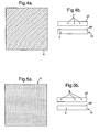
- Each track (2, 3) is divided into areas of individualized diffractive structures (4, 5) for example illustrated in Figs. (4a) and (5a ), and generating a code corresponding to a unique position of the support (1).
- the diffractive tracks (2, 3) may also be produced with transparency or refractive index modulation.
- Fig. 3b shows an exemplary embodiment in which the rigid disk only includes a single diffractive track (2).
- the latter may however consist of several adjacent diffractive annular sectors.
- the disks may be subject to error due to manufacturing imperfections, dirt, damage or degradation.
- other potential sources of bit errors include manufacturing imperfections in the encoded disk, damage occurring after manufacture, accumulation of foreign matter such as dirt on a lens, mirror, or sensing array, electrical noise, abnormalities in the signal processing algorithms that could cause misinterpretation of a 1 or 0; and mechanical misalignment of the components.
- These sources of error include scratches, blemishes or other physical defects in the disk itself, scratches, blemishes or other physical defects in the detector array, electrical transients (noise) throughout the system, calculation errors in the adaptive threshold algorithms or other parts of the software, A/D conversion errors, and foreign contamination (dirt) of the signal anywhere throughout the optical path.
- each obtained code is for example materialized in Figs. (4b) and (5b ).
- Each area of individualized diffractive structure for example includes a plurality of elementary shapes positioned as a grid of these shapes, for example as 128 x 128 or 128 x 256.
- the optical signal forming the optical code defining a particular position of the support relatively to the beam for example consists of diffractive light spots (6, 7, 8, 9), i.e., in the case in point, light spots of the first diffraction order and, if necessary, of its conjugate (not shown). The following diffraction orders are not utilized but retained in the diffracted optical signal.
- FIG. 4b An exemplary first diffraction order is marked by reference 10 in Figs. 4b and 5b .
- the use of the second diffraction order and, if need be, its conjugate order, may also be contemplated.
- each diffracted track (2) or (3) is divided into angular sectors with equal surfaces forming the individualized diffractive structures.
- the angular sectors have dimensions of the order of 10 ⁇ m to 100 ⁇ m.
- Each diffracted track (2) or (3) preferably comprises at least 3,600 angular sectors in order to obtain accuracy less than 0.1° in determining the position of the support.
- the diffractive track (2, 3) is positioned on a self-adhesive support.
- the latter may then be added, or more particularly adhered, onto any support and notably onto a support with a cylindrical aspect of the steering column shaft type.
- the dimensions of the diffractive support (1) may thereby be adapted to a location or to a particular shape. Reduced bulkiness and a large flexibility to use are obtained for the diffractive support (1).
- Figs. 6-9 four successive positions of a diffracting support, relatively to a fixed mark, have been schematized.
- This fixed mark is materialized by a fixed diaphragm and/or collimating unit (12) associated with the light source.
- the diffractive support (1) includes individualized diffractive structures (13) and the displacement is materialized behind the unit (12) in Figs. 6-9 .
- a diffracted code (10) which varies according to the position of the individualized diffractive structure (13) and consequently of the diffractive support (1) relatively to the collimating unit.
- the diffracted code (1) which corresponds to the first diffraction order therefore has a development transcribed via detection means with a threshold level, which measure light intensity variations for example. Three light spots reaching a maximum intensity level Imax as well as a spot without light are thereby obtained in Fig. 6 . A code in the form of 1 1 1 0 is thereby obtained via transformation means of the analog/digital converter type.
- an angular deviation of the individualized diffraction structure (13) is expressed by another light distribution over the diffraction spots. Three light spots with reduced light intensity but with a level larger than the minimum detection level Io, are thereby obtained.
- the fourth spot then passes from a spot without light to a spot with low intensity less than the minimum level Io.
- the thereby obtained digital optical code thus remains unchanged.
- further rotation of the individualized diffractive structure (13) is expressed by a distribution of the light intensity in the first diffraction order so as none of said light spots are detected. The detected intensity actually is less than the minimum level Io.
- the optical code translated as 0 0 0 0, is thereby obtained.
- the 0 levels are very conspicuous and materialized by dotted lines in Figs. 6-9 and levels 1 are materialized by bold lines.
- a unique optical code is thereby obtained according to a level of resolution determined by the system.
- the present invention also relates to a device for measuring the position of a first component in relative motion with respect to a second component.
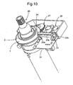
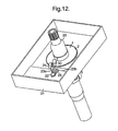
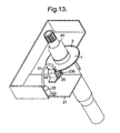
- a device for measuring the position of a first component in relative motion with respect to a second component Such a measuring device and more specifically different alternative embodiments of this device are for example illustrated in Figs. 10-17 .
- a steering column (20) onto which the diffracted support (1) is added.
- the latter for example has on its periphery a ring-shaped diffractive track (2).
- the diffractive support (1) is permanently attached to a rotary shaft by any known means.
- the measuring device according to the invention is positioned adjacent to the diffractive support (1) on a fixed support (21).
- the measuring device includes a light source (22) emitting an incident beam (23a) crossing the diffractive track (2).
- the illustrated exemplary embodiment thus operates by transmission on the diffractive support (1).
- the incident beam (23a) is diffracted at (23b) by the diffractive track (2).
- This diffracted beam (23b) is then guided via an assembly (24) for example including a wave guide and mirrors, towards detection means (25).
- the latter are controlled by adequate electronic means, with which the different optical codes diffracted by the diffractive support (1) during its rotation may be analyzed.
- a set of gears (27) is also provided for driving a complementary diffractive support at a different rotational velocity, thereby enabling the number of revolutions to be counted and the absolute position to be coded over the whole steering wheel travel i.e., as a rule, plus or minus 4 or 5 revolutions,.
- the detection and reading means (25) are positioned at least partly directly under a peripheral area of the diffractive support (1).
- the light source (22) emits an incident beam (23a) which is notably directed via a set of mirrors (24) onto the upper surface of the diffractive track (2).
- the diffracted code optical signal is then read by transmission under the diffractive support (1).
- the diffractive support (1) is associated with a toothed wheel (28), which drives a complementary set of gears (29).
- a set of gears (29) is also provided, the function of which is identical with that of the set of gears (27).
- the diffractive track may be directly added onto the toothed wheel (28) which thereby forms the diffractive support.
- the toothed wheel (28) is made in a transparent material for the incident beam (23a).
- the measuring device comprises an optical unit (30) with which a diaphragm may be made in order to conform the incident optical beam (23a).
- the fixed light source (22) is associated with an optical guide (31) sending the light ray onto the diffractive track (2).
- the diffracted beam (23b) is then read by the detection means (25) by transmission.
- the optical guide (31) is for example made with optical fibers.
- the diffractive support (1) is positioned under the toothed wheel (28).
- the fixed light source (22) is also positioned under the diffractive support (1) and emits an incident beam tilted relatively to the normal so as to obtain a diffracted beam directed towards the reading means (25).
- the positioning and the orientation of the fixed light source (22) on the one hand and of the reading detection means (25) on the other hand may be optimized.
- a diffractive track (2) positioned on an annular section for example extending taperwise relatively to the axis of rotation. With diffraction by reflection on this tapered section including the diffractive track (2), it is also possible to optimize the positioning of the light source (22) on the one hand and that of the detection means (25) on the other hand.
- the steering column (20) is permanently attached to a toothed wheel (33) and the diffractive support (1) is not directly mounted on said steering column (20). It is rotationally mounted on the fixed support (21) and driven into rotation by the toothed wheel (33) via an intermediate toothed wheel (34).
- the fixed light source (22) is positioned on the fixed support (21) and under the diffractive support (1).
- the incident beam is thereby diffracted by the track (2) by transmission and guided via a set of mirrors (24) towards the detection and reading means (25), which are associated with electronic processing and analysis means (26) which are also provided on said fixed support (21).
- This exemplary embodiment of the device for measuring and determining the position of the diffractive support (1) has the advantage of merging the components of the device into a fixed sub-assembly adjacent to the steering column (20). The thereby achieved sub-assembly may thus be manufactured and assembled distinctly from the assembling of the steering column (20).
- Fig. 16 Another exemplary embodiment according to the invention is for example illustrated in Fig. 16 .
- the incident beam (23a) is directed with a determined angle of incidence onto a mirror (36).
- the latter then redirects the incident beams (23a) onto the diffractive track (2) which emits par transmission the diffracted beam towards the reading and detection means (25).
- the mirror (36) By turning the mirror (36), it is possible to optimize the relative positioning between the light source (22) and the reading and detection means (25).
- the rotation of the diffractive support (1) also drives an additional set of gears (37), the function of which is identical with that of the set of gears (27).
- the diffractive track (2) is directly added to the steering column (20) and more particularly onto a cylindrical portion.
- the diffractive track is for example added via a self-adhesive support onto this cylindrical portion.
- the light source (22) thus emits the incident beam (23a) towards the diffractive track (2) along a direction extending substantially in a plane normal to the axis of rotation R.
- the diffractive track (2) does almost not increase the radial bulkiness of the steering column (20).
- the latter is associated with a toothed wheel (38) as well as with an additional set of gears (39), the function of which is identical with that of the set of gears (27).
- Fig. 18 illustrates an exemplary embodiment of a measuring device according to the invention.
- an incident beam (50) passes through a fixed diaphragm (51).
- the incident beam (50) is sent onto diffractive supports (52, 53) which may move according to movements illustrated by the arrows D.
- the incident beam is diffracted at (51) by the diffractive support. It is then focused by the lens (55). Light spots (50a, 50b) corresponding to portions of the constituent signal of the selected diffraction order and of its conjugate are thereby obtained in a plane (56) containing fixed detection means. Diffraction order 0 is marked on the optical axis AO with reference (58).
- FIG. 19 an example of conformation of the incident beam (50) is seen for example.
- the incident beam (50) thereby covers two distinct diffractive supports (1c, 1d).
- the diffractive supports (1c, 1d) include diffractive tracks (52, 53) with annular extension, respectively.
- the second diffractive support (1d) in this case, for example by turning in the direction R 2 at a lower velocity than the first diffractive support (1c) rotating in the R 1 direction, allows the number of revolutions to be counted for parts in relative rotation.
- a complementary diffractive track (59) is also provided on the first diffractive support (1c) allowing light synchronization spots to be generated, as well as another complementary diffractive track (60) allowing light calibration spots to be generated for example.
- the incident optical beam (50) for example from a laser source, partially covers because of its conformation, the diffractive tracks (52, 53) for a specific position in a specific rotational revolution.
- the basic geometrical shapes, constituent of the diffractive components, are recorded for example on computer files and are ready to be manufactured for example by microlithography on a silicon, quartz, or glass wafer.
- the diffracted optical signal according to the method in accordance with the invention is illustrated as an example in Fig. 20 .
- the latter shows light spots, the intensity of which is more or less intense, where the diffraction order 0 (58) localized on the optical axis A0, may be identified as well as the first positive diffraction order (61a) and the first negative diffraction order (61b).
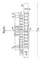
- Fig. 21 illustrates a detail of a diffracted optical signal created on the detection means after focusing with the fixed lens (55).
- a coded optical signal on the detection means comprising a main coded signal (64) on 12 bits, synchronization signals (65) (light spots), and 4-bit optical counting signals (66) reflecting the number of revolutions accomplished by one of the two components in relative rotation.
- optical calibration signals are also found on the detection array (68).
- Fig. 21 also shows complementary diffracted optical signals (70), not considered in this example by the detection means, but being used for uniformizing the intensity of the detected light spots.
Landscapes
- Physics & Mathematics (AREA)
- General Physics & Mathematics (AREA)
- Length Measuring Devices By Optical Means (AREA)
- Optical Transform (AREA)
- Paper (AREA)
- Vehicle Body Suspensions (AREA)
- Apparatus For Radiation Diagnosis (AREA)
Claims (14)
- Verfahren zum Ermitteln der Position von einer von zwei Komponenten in relativer Bewegung in Bezug aufeinander unter Verwendung von optischen Mitteln und umfassend:Richten von wenigstens einem Lichtstrahl, der von einer an einer Komponente angebrachten Lichtquelle emittiert wird, auf einen an der zweiten Komponente angebrachten diffraktiven Träger, der so berechnet und hergestellt ist, dass er ein optisches Signal erzeugt, das die Positionierung des genannten Trägers anzeigt, wobei das optische Signal von dem diffraktiven Träger in Transmission und/oder in Reflexion erzeugt wird und wobei das optische Signal eine Information aufweist, die seine Qualität anzeigt;Erkennen und Lesen von wenigstens einem von dem genannten Signal gebildeten optischen Code, der einer eindeutigen Position des diffraktiven Trägers relativ zu dem Strahl entspricht und wobei der Code eine Information aufweist, die die Qualität des Signals anzeigt;Prüfen der Qualität des Signals;Zuordnen einer Position zu jedem erkannten optischen Code undAusgeben eines Signals, das die genannte Position anzeigt, an den genannten Benutzer;dadurch gekennzeichnet, dass jeder erkannte und gelesene optische Code zum Ermitteln der Position des diffraktiven Trägers mit in einer Speichertabelle gespeicherten elektronischen Codes verglichen wird,und dadurch, dass jeder einer Position des diffraktiven Trägers entsprechende optische Code wenigstens eine optische Synchronisationsstruktur aufweist, deren Erkennung die Auslösung der Lesephase des optischen Signals zulässt, das den Code einer Position des diffraktiven Trägers relativ zu dem Strahl integriert.
- Verfahren nach Anspruch 1, bei dem die die Qualität des Signals anzeigende Information ein Paritätscode ist.
- Verfahren nach Anspruch 1, bei dem die die Qualität des Signals anzeigende Information ein Prüfsummencode ist.
- Verfahren nach Anspruch 1, bei dem die die Qualität des Signals anzeigende Information eine zyklische Redundanz ist.
- Verfahren nach Anspruch 1, bei dem der von jedem optischen Signal gebildete optische Code als optische Strukturen erscheint, auf deren Basis Bits eines elektronischen Codes von Mitteln zum Erkennen und Lesen der genannten Strukturen erzeugt werden.
- Verfahren nach Anspruch 1, bei dem der beugungsoptische Code wenigstens eine optische Anfangsstruktur und wenigstens eine optische Endstruktur aufweist, die den Lesebereich für das optische Signal begrenzen, der einer Position des diffraktiven Trägers relativ zu dem Strahl entspricht.
- Verfahren nach Anspruch 5, bei dem jeder erkannte und gelesene Code einem Algorithmus unterzogen wird zum Berechnen der Position des diffraktiven Trägers relativ zu dem Strahl.
- Verfahren nach Anspruch 1, bei dem jeder optische Code, der einer identifizierbaren Position entspricht, wenigstens eine optische Kalibrierungsstruktur hat, die zum Zweck der Diagnose einer richtigen Ausleseoperation verwendet wird.
- Verfahren nach Anspruch 8, bei dem die optischen Strukturen aus wenigstens einem Lichtpunkt bestehen, dessen Lichtstärke gemessen wird.
- Verfahren nach Anspruch 5, bei dem die Codes, die die Position einer Komponente relativ zu der anderen definieren, in ihrer Reihenfolge mit dem GRAY-Code übereinstimmen.
- Verfahren nach Anspruch 9, bei dem die Helligkeitsvariationen von wenigstens einem der Punkte, die die optischen Strukturen bilden, mit Hilfe eines Analog-Digital-Umsetzers codiert werden, wobei binäres oder Graupegel-Auslesen bereitgestellt wird.
- Verfahren nach Anspruch 1, bei dem die Lichtquelle gemäß einer Frequenz gepulst wird, die von der Geschwindigkeit der in Bewegung befindlichen Komponenten gesteuert wird, wobei das Auslesen mit der Erzeugung des/der Lichtstrahl(en) synchronisiert wird.
- Verfahren nach Anspruch 1, ferner umfassend den Schritt des Ermittelns der Winkelposition von einer der Komponenten im Verhältnis zueinander.
- Verfahren nach Anspruch 1, bei dem die Anzahl optischer Punkte oder Strukturen, die zum Codieren der Winkelposition verwendet wird, wenigstens gleich 12 ist, um eine Winkelauflösung von weniger als 0,1° bereitzustellen.
Applications Claiming Priority (1)
| Application Number | Priority Date | Filing Date | Title |
|---|---|---|---|
| US11/317,744 US7476843B2 (en) | 2005-12-23 | 2005-12-23 | Method for determining the position of a first moving component relative to a second component and device for applying said method |
Publications (2)
| Publication Number | Publication Date |
|---|---|
| EP1801547A1 EP1801547A1 (de) | 2007-06-27 |
| EP1801547B1 true EP1801547B1 (de) | 2009-03-18 |
Family
ID=37762275
Family Applications (1)
| Application Number | Title | Priority Date | Filing Date |
|---|---|---|---|
| EP06077188A Not-in-force EP1801547B1 (de) | 2005-12-23 | 2006-12-07 | Verfahren und Vorrichtung zur Bestimmung der Position eines ersten Teils relativ zu einem zweiten |
Country Status (4)
| Country | Link |
|---|---|
| US (2) | US7476843B2 (de) |
| EP (1) | EP1801547B1 (de) |
| AT (1) | ATE426146T1 (de) |
| DE (1) | DE602006005776D1 (de) |
Families Citing this family (8)
| Publication number | Priority date | Publication date | Assignee | Title |
|---|---|---|---|---|
| EP1862773A1 (de) * | 2006-05-31 | 2007-12-05 | Delphi Technologies, Inc. | Kontaktloser Schalter |
| US8886471B2 (en) | 2008-06-26 | 2014-11-11 | Infineon Technologies Ag | Rotation sensing method and system |
| DE102009040790B4 (de) * | 2009-09-09 | 2012-10-25 | Universität Stuttgart | Verfahren zur optischen Kompensation der Maßspurdezentrierung bei Drehwinkelsensoren |
| EP2636998B1 (de) * | 2012-03-08 | 2014-05-14 | Siemens Aktiengesellschaft | Messwertgeber zum Erhalt einer Positionsinformation und Verfahren zu dessen Betrieb |
| US9134142B2 (en) * | 2013-03-14 | 2015-09-15 | Charles R. Kirk | Rotary encoder with free floating flexible sensor carrier |
| EP3399336B1 (de) | 2017-05-05 | 2022-03-16 | Leuze electronic GmbH + Co. KG | Positioniervorrichtung |
| DE102019101966A1 (de) * | 2019-01-28 | 2020-07-30 | Valeo Schalter Und Sensoren Gmbh | Positionserfassungseinrichtung für eine Lichtsignalumlenkeinrichtung einer optischen Messvorrichtung zur Erfassung von Objekten, Lichtsignalumlenkeinrichtung, Messvorrichtung und Verfahren zum Betreiben einer Positionserfassungseinrichtung |
| CN119940442B (zh) * | 2025-04-07 | 2025-06-10 | 清华大学 | 大规模可重构衍射光计算芯片系统与架构 |
Family Cites Families (17)
| Publication number | Priority date | Publication date | Assignee | Title |
|---|---|---|---|---|
| DE8717558U1 (de) * | 1987-02-21 | 1989-02-23 | Dr. Johannes Heidenhain Gmbh, 8225 Traunreut | Lichtelektrische Positionsmeßeinrichtung |
| US5066130A (en) * | 1988-05-10 | 1991-11-19 | Canon Kabushiki Kaisha | Displacement measuring apparatus |
| US5021646A (en) * | 1990-01-25 | 1991-06-04 | Spectra-Physics, Inc. | Remote optical path for capillary electrophoresis instrument |
| GB9109890D0 (en) * | 1991-05-08 | 1991-08-21 | Marconi Gec Ltd | Apparatus and method for sensing the relative position of two members |
| US6093928A (en) * | 1994-12-22 | 2000-07-25 | Ohtomo; Fumio | Position measuring rotary incremental optical encoder |
| EP0729013B1 (de) | 1995-02-21 | 2002-07-17 | Canon Kabushiki Kaisha | Vorrichtung zur Bestimmung einer Verschiebung und deren Verwendung in einer Einrichtung zur Antriebsregelung |
| JPH10185624A (ja) * | 1996-12-25 | 1998-07-14 | Harmonic Drive Syst Ind Co Ltd | 光学式ポテンショメータ |
| US5965879A (en) * | 1997-05-07 | 1999-10-12 | The United States Of America As Represented By The Administrator Of The National Aeronautics And Space Administration | Method and apparatus for ultra-high-sensitivity, incremental and absolute optical encoding |
| US5936236A (en) * | 1997-11-26 | 1999-08-10 | Renco Encoders, Inc. | Method for generating a synthetic reference signal for comparison with scanning signals of a position measuring device |
| US6424407B1 (en) | 1998-03-09 | 2002-07-23 | Otm Technologies Ltd. | Optical translation measurement |
| EP1003012B3 (de) * | 1998-11-19 | 2011-04-20 | Dr. Johannes Heidenhain GmbH | Optische Positionsmesseinrichtung |
| KR20050014795A (ko) * | 2002-03-06 | 2005-02-07 | 어드밴스드 포토메트릭스, 인크. | 복사 인코딩 및 분석을 위한 방법 및 장치 |
| US6963063B2 (en) * | 2003-05-22 | 2005-11-08 | Renco Encoders Inc. | Use of non-interdigitated commutation sensors on Opto-ASICS to achieve low CPR non-standard encoder resolutions |
| US7112781B2 (en) * | 2004-04-21 | 2006-09-26 | Avago Technologies Ecbu Ip (Singapore) Pte. Ltd. | Absolute encoder |
| US7126109B2 (en) * | 2004-06-14 | 2006-10-24 | Gsi Group Corporation | Encoder scale error compensation employing comparison among multiple detectors |
| ES2322151T3 (es) * | 2004-12-30 | 2009-06-17 | Delphi Technologies Inc. | Procedimiento de determinacion de la posicion de un primer elemento en movimiento relativo a un segundo elemento y dispositivo para implementar dicho procedimiento. |
| US7462815B2 (en) * | 2005-12-13 | 2008-12-09 | Avago Technologies General Ip (Singapore) Pte. Ltd. | Absolute encoder utilizing a code pattern carrier having a varying mixture of phosphors deposited thereon |
-
2005
- 2005-12-23 US US11/317,744 patent/US7476843B2/en not_active Expired - Fee Related
-
2006
- 2006-12-07 AT AT06077188T patent/ATE426146T1/de not_active IP Right Cessation
- 2006-12-07 DE DE602006005776T patent/DE602006005776D1/de active Active
- 2006-12-07 EP EP06077188A patent/EP1801547B1/de not_active Not-in-force
-
2008
- 2008-12-05 US US12/315,705 patent/US7842913B2/en not_active Expired - Fee Related
Also Published As
| Publication number | Publication date |
|---|---|
| US7476843B2 (en) | 2009-01-13 |
| EP1801547A1 (de) | 2007-06-27 |
| DE602006005776D1 (de) | 2009-04-30 |
| US7842913B2 (en) | 2010-11-30 |
| US20070146730A1 (en) | 2007-06-28 |
| ATE426146T1 (de) | 2009-04-15 |
| US20090147271A1 (en) | 2009-06-11 |
Similar Documents
| Publication | Publication Date | Title |
|---|---|---|
| US7842913B2 (en) | Method for determining the position of a first moving component relative to a second component and device for applying said method | |
| US5107107A (en) | Laser optical disk position encoder with active heads | |
| JP5479236B2 (ja) | ロータリーエンコーダ | |
| US8085394B2 (en) | Optoelectronic longitudinal measurement method and optoelectronic longitudinal measurement device | |
| JP2010501068A (ja) | 軸周りの回転角度を測定する光電子角度センサとその測定方法 | |
| US7538312B2 (en) | Method for determining the position of a first moving component relatively to a second component and device for applying said method | |
| JPH02285214A (ja) | 測長器及びそれに用いるスケール部材 | |
| JPH067062B2 (ja) | 位置検出装置 | |
| US10502593B1 (en) | Linear and rotary multitrack absolute position encoder and methods using the same | |
| US7586621B2 (en) | Displacement-measuring optical scale and optical encoder using same | |
| US8637804B2 (en) | Rotary position encoder | |
| JP2009535634A (ja) | ロータリエンコーダ装置 | |
| US5602388A (en) | Absolute and directional encoder using optical disk | |
| Chen et al. | High-precision digital rotary encoder based on dot-matrix gratings | |
| US8093546B2 (en) | Out-of-round coder | |
| US10963724B2 (en) | Absolute position encoder using a focused laser beam to detect position code words | |
| JP4908764B2 (ja) | 光学式エンコーダ | |
| EP3563118B1 (de) | System und verfahren zur optischen codierung | |
| JP6875923B2 (ja) | スケール装置および二軸変位検出装置 | |
| EP2275782B1 (de) | Absoluter Drehgeber mit hoher Auflösung | |
| US20080074672A1 (en) | High Resolution position coder | |
| JP2010066129A (ja) | アブソリュート型リニアエンコーダとアクチュエータ | |
| JPH08226804A (ja) | 変位情報検出装置及びこれを用いたドライブ制御装置 | |
| JPH09126723A (ja) | 変位情報検出装置 | |
| JPS63293413A (ja) | エンコ−ダ |
Legal Events
| Date | Code | Title | Description |
|---|---|---|---|
| PUAI | Public reference made under article 153(3) epc to a published international application that has entered the european phase |
Free format text: ORIGINAL CODE: 0009012 |
|
| AK | Designated contracting states |
Kind code of ref document: A1 Designated state(s): AT BE BG CH CY CZ DE DK EE ES FI FR GB GR HU IE IS IT LI LT LU LV MC NL PL PT RO SE SI SK TR |
|
| AX | Request for extension of the european patent |
Extension state: AL BA HR MK YU |
|
| 17P | Request for examination filed |
Effective date: 20071227 |
|
| AKX | Designation fees paid |
Designated state(s): AT BE BG CH CY CZ DE DK EE ES FI FR GB GR HU IE IS IT LI LT LU LV MC NL PL PT RO SE SI SK TR |
|
| 17Q | First examination report despatched |
Effective date: 20080208 |
|
| GRAP | Despatch of communication of intention to grant a patent |
Free format text: ORIGINAL CODE: EPIDOSNIGR1 |
|
| RTI1 | Title (correction) |
Free format text: METHOD FOR DETERMINING THE POSITION OF A FIRST MOVING COMPONENT RELATIVE TO A SECOND COMPONENT AND DEVICE FOR APPLYING SAID METHOD |
|
| GRAS | Grant fee paid |
Free format text: ORIGINAL CODE: EPIDOSNIGR3 |
|
| GRAA | (expected) grant |
Free format text: ORIGINAL CODE: 0009210 |
|
| AK | Designated contracting states |
Kind code of ref document: B1 Designated state(s): AT BE BG CH CY CZ DE DK EE ES FI FR GB GR HU IE IS IT LI LT LU LV MC NL PL PT RO SE SI SK TR |
|
| REG | Reference to a national code |
Ref country code: GB Ref legal event code: FG4D |
|
| REG | Reference to a national code |
Ref country code: CH Ref legal event code: EP |
|
| REG | Reference to a national code |
Ref country code: IE Ref legal event code: FG4D |
|
| REF | Corresponds to: |
Ref document number: 602006005776 Country of ref document: DE Date of ref document: 20090430 Kind code of ref document: P |
|
| PG25 | Lapsed in a contracting state [announced via postgrant information from national office to epo] |
Ref country code: LT Free format text: LAPSE BECAUSE OF FAILURE TO SUBMIT A TRANSLATION OF THE DESCRIPTION OR TO PAY THE FEE WITHIN THE PRESCRIBED TIME-LIMIT Effective date: 20090318 Ref country code: FI Free format text: LAPSE BECAUSE OF FAILURE TO SUBMIT A TRANSLATION OF THE DESCRIPTION OR TO PAY THE FEE WITHIN THE PRESCRIBED TIME-LIMIT Effective date: 20090318 Ref country code: SI Free format text: LAPSE BECAUSE OF FAILURE TO SUBMIT A TRANSLATION OF THE DESCRIPTION OR TO PAY THE FEE WITHIN THE PRESCRIBED TIME-LIMIT Effective date: 20090318 Ref country code: NL Free format text: LAPSE BECAUSE OF FAILURE TO SUBMIT A TRANSLATION OF THE DESCRIPTION OR TO PAY THE FEE WITHIN THE PRESCRIBED TIME-LIMIT Effective date: 20090318 |
|
| PG25 | Lapsed in a contracting state [announced via postgrant information from national office to epo] |
Ref country code: PL Free format text: LAPSE BECAUSE OF FAILURE TO SUBMIT A TRANSLATION OF THE DESCRIPTION OR TO PAY THE FEE WITHIN THE PRESCRIBED TIME-LIMIT Effective date: 20090318 Ref country code: LV Free format text: LAPSE BECAUSE OF FAILURE TO SUBMIT A TRANSLATION OF THE DESCRIPTION OR TO PAY THE FEE WITHIN THE PRESCRIBED TIME-LIMIT Effective date: 20090318 Ref country code: AT Free format text: LAPSE BECAUSE OF FAILURE TO SUBMIT A TRANSLATION OF THE DESCRIPTION OR TO PAY THE FEE WITHIN THE PRESCRIBED TIME-LIMIT Effective date: 20090318 Ref country code: SE Free format text: LAPSE BECAUSE OF FAILURE TO SUBMIT A TRANSLATION OF THE DESCRIPTION OR TO PAY THE FEE WITHIN THE PRESCRIBED TIME-LIMIT Effective date: 20090618 |
|
| NLV1 | Nl: lapsed or annulled due to failure to fulfill the requirements of art. 29p and 29m of the patents act | ||
| PG25 | Lapsed in a contracting state [announced via postgrant information from national office to epo] |
Ref country code: BE Free format text: LAPSE BECAUSE OF FAILURE TO SUBMIT A TRANSLATION OF THE DESCRIPTION OR TO PAY THE FEE WITHIN THE PRESCRIBED TIME-LIMIT Effective date: 20090318 |
|
| PG25 | Lapsed in a contracting state [announced via postgrant information from national office to epo] |
Ref country code: CZ Free format text: LAPSE BECAUSE OF FAILURE TO SUBMIT A TRANSLATION OF THE DESCRIPTION OR TO PAY THE FEE WITHIN THE PRESCRIBED TIME-LIMIT Effective date: 20090318 Ref country code: ES Free format text: LAPSE BECAUSE OF FAILURE TO SUBMIT A TRANSLATION OF THE DESCRIPTION OR TO PAY THE FEE WITHIN THE PRESCRIBED TIME-LIMIT Effective date: 20090629 Ref country code: EE Free format text: LAPSE BECAUSE OF FAILURE TO SUBMIT A TRANSLATION OF THE DESCRIPTION OR TO PAY THE FEE WITHIN THE PRESCRIBED TIME-LIMIT Effective date: 20090318 Ref country code: PT Free format text: LAPSE BECAUSE OF FAILURE TO SUBMIT A TRANSLATION OF THE DESCRIPTION OR TO PAY THE FEE WITHIN THE PRESCRIBED TIME-LIMIT Effective date: 20090827 |
|
| PG25 | Lapsed in a contracting state [announced via postgrant information from national office to epo] |
Ref country code: IS Free format text: LAPSE BECAUSE OF FAILURE TO SUBMIT A TRANSLATION OF THE DESCRIPTION OR TO PAY THE FEE WITHIN THE PRESCRIBED TIME-LIMIT Effective date: 20090718 Ref country code: SK Free format text: LAPSE BECAUSE OF FAILURE TO SUBMIT A TRANSLATION OF THE DESCRIPTION OR TO PAY THE FEE WITHIN THE PRESCRIBED TIME-LIMIT Effective date: 20090318 Ref country code: RO Free format text: LAPSE BECAUSE OF FAILURE TO SUBMIT A TRANSLATION OF THE DESCRIPTION OR TO PAY THE FEE WITHIN THE PRESCRIBED TIME-LIMIT Effective date: 20090318 |
|
| PLBE | No opposition filed within time limit |
Free format text: ORIGINAL CODE: 0009261 |
|
| STAA | Information on the status of an ep patent application or granted ep patent |
Free format text: STATUS: NO OPPOSITION FILED WITHIN TIME LIMIT |
|
| PG25 | Lapsed in a contracting state [announced via postgrant information from national office to epo] |
Ref country code: DK Free format text: LAPSE BECAUSE OF FAILURE TO SUBMIT A TRANSLATION OF THE DESCRIPTION OR TO PAY THE FEE WITHIN THE PRESCRIBED TIME-LIMIT Effective date: 20090318 Ref country code: BG Free format text: LAPSE BECAUSE OF FAILURE TO SUBMIT A TRANSLATION OF THE DESCRIPTION OR TO PAY THE FEE WITHIN THE PRESCRIBED TIME-LIMIT Effective date: 20090618 |
|
| 26N | No opposition filed |
Effective date: 20091221 |
|
| PG25 | Lapsed in a contracting state [announced via postgrant information from national office to epo] |
Ref country code: MC Free format text: LAPSE BECAUSE OF NON-PAYMENT OF DUE FEES Effective date: 20100701 |
|
| REG | Reference to a national code |
Ref country code: IE Ref legal event code: MM4A |
|
| PG25 | Lapsed in a contracting state [announced via postgrant information from national office to epo] |
Ref country code: IE Free format text: LAPSE BECAUSE OF NON-PAYMENT OF DUE FEES Effective date: 20091207 Ref country code: GR Free format text: LAPSE BECAUSE OF FAILURE TO SUBMIT A TRANSLATION OF THE DESCRIPTION OR TO PAY THE FEE WITHIN THE PRESCRIBED TIME-LIMIT Effective date: 20090619 |
|
| PG25 | Lapsed in a contracting state [announced via postgrant information from national office to epo] |
Ref country code: IT Free format text: LAPSE BECAUSE OF FAILURE TO SUBMIT A TRANSLATION OF THE DESCRIPTION OR TO PAY THE FEE WITHIN THE PRESCRIBED TIME-LIMIT Effective date: 20090318 |
|
| PG25 | Lapsed in a contracting state [announced via postgrant information from national office to epo] |
Ref country code: LU Free format text: LAPSE BECAUSE OF NON-PAYMENT OF DUE FEES Effective date: 20091207 |
|
| PG25 | Lapsed in a contracting state [announced via postgrant information from national office to epo] |
Ref country code: HU Free format text: LAPSE BECAUSE OF FAILURE TO SUBMIT A TRANSLATION OF THE DESCRIPTION OR TO PAY THE FEE WITHIN THE PRESCRIBED TIME-LIMIT Effective date: 20090919 |
|
| REG | Reference to a national code |
Ref country code: CH Ref legal event code: PL |
|
| PG25 | Lapsed in a contracting state [announced via postgrant information from national office to epo] |
Ref country code: TR Free format text: LAPSE BECAUSE OF FAILURE TO SUBMIT A TRANSLATION OF THE DESCRIPTION OR TO PAY THE FEE WITHIN THE PRESCRIBED TIME-LIMIT Effective date: 20090318 |
|
| PG25 | Lapsed in a contracting state [announced via postgrant information from national office to epo] |
Ref country code: CY Free format text: LAPSE BECAUSE OF FAILURE TO SUBMIT A TRANSLATION OF THE DESCRIPTION OR TO PAY THE FEE WITHIN THE PRESCRIBED TIME-LIMIT Effective date: 20090318 |
|
| PG25 | Lapsed in a contracting state [announced via postgrant information from national office to epo] |
Ref country code: LI Free format text: LAPSE BECAUSE OF NON-PAYMENT OF DUE FEES Effective date: 20101231 Ref country code: CH Free format text: LAPSE BECAUSE OF NON-PAYMENT OF DUE FEES Effective date: 20101231 |
|
| PGFP | Annual fee paid to national office [announced via postgrant information from national office to epo] |
Ref country code: DE Payment date: 20131230 Year of fee payment: 8 Ref country code: GB Payment date: 20131227 Year of fee payment: 8 |
|
| PGFP | Annual fee paid to national office [announced via postgrant information from national office to epo] |
Ref country code: FR Payment date: 20131217 Year of fee payment: 8 |
|
| REG | Reference to a national code |
Ref country code: DE Ref legal event code: R119 Ref document number: 602006005776 Country of ref document: DE |
|
| GBPC | Gb: european patent ceased through non-payment of renewal fee |
Effective date: 20141207 |
|
| REG | Reference to a national code |
Ref country code: FR Ref legal event code: ST Effective date: 20150831 |
|
| PG25 | Lapsed in a contracting state [announced via postgrant information from national office to epo] |
Ref country code: GB Free format text: LAPSE BECAUSE OF NON-PAYMENT OF DUE FEES Effective date: 20141207 Ref country code: DE Free format text: LAPSE BECAUSE OF NON-PAYMENT OF DUE FEES Effective date: 20150701 |
|
| PG25 | Lapsed in a contracting state [announced via postgrant information from national office to epo] |
Ref country code: FR Free format text: LAPSE BECAUSE OF NON-PAYMENT OF DUE FEES Effective date: 20141231 |