EP3563118B1 - System und verfahren zur optischen codierung - Google Patents
System und verfahren zur optischen codierung Download PDFInfo
- Publication number
- EP3563118B1 EP3563118B1 EP17887137.2A EP17887137A EP3563118B1 EP 3563118 B1 EP3563118 B1 EP 3563118B1 EP 17887137 A EP17887137 A EP 17887137A EP 3563118 B1 EP3563118 B1 EP 3563118B1
- Authority
- EP
- European Patent Office
- Prior art keywords
- encoder
- substrate
- light
- disc
- optical
- Prior art date
- Legal status (The legal status is an assumption and is not a legal conclusion. Google has not performed a legal analysis and makes no representation as to the accuracy of the status listed.)
- Active
Links
Images


Classifications
-
- G—PHYSICS
- G01—MEASURING; TESTING
- G01D—MEASURING NOT SPECIALLY ADAPTED FOR A SPECIFIC VARIABLE; ARRANGEMENTS FOR MEASURING TWO OR MORE VARIABLES NOT COVERED IN A SINGLE OTHER SUBCLASS; TARIFF METERING APPARATUS; MEASURING OR TESTING NOT OTHERWISE PROVIDED FOR
- G01D5/00—Mechanical means for transferring the output of a sensing member; Means for converting the output of a sensing member to another variable where the form or nature of the sensing member does not constrain the means for converting; Transducers not specially adapted for a specific variable
- G01D5/26—Mechanical means for transferring the output of a sensing member; Means for converting the output of a sensing member to another variable where the form or nature of the sensing member does not constrain the means for converting; Transducers not specially adapted for a specific variable characterised by optical transfer means, i.e. using infrared, visible, or ultraviolet light
- G01D5/32—Mechanical means for transferring the output of a sensing member; Means for converting the output of a sensing member to another variable where the form or nature of the sensing member does not constrain the means for converting; Transducers not specially adapted for a specific variable characterised by optical transfer means, i.e. using infrared, visible, or ultraviolet light with attenuation or whole or partial obturation of beams of light
- G01D5/34—Mechanical means for transferring the output of a sensing member; Means for converting the output of a sensing member to another variable where the form or nature of the sensing member does not constrain the means for converting; Transducers not specially adapted for a specific variable characterised by optical transfer means, i.e. using infrared, visible, or ultraviolet light with attenuation or whole or partial obturation of beams of light the beams of light being detected by photocells
- G01D5/347—Mechanical means for transferring the output of a sensing member; Means for converting the output of a sensing member to another variable where the form or nature of the sensing member does not constrain the means for converting; Transducers not specially adapted for a specific variable characterised by optical transfer means, i.e. using infrared, visible, or ultraviolet light with attenuation or whole or partial obturation of beams of light the beams of light being detected by photocells using displacement encoding scales
- G01D5/34707—Scales; Discs, e.g. fixation, fabrication, compensation
- G01D5/34715—Scale reading or illumination devices
-
- G—PHYSICS
- G01—MEASURING; TESTING
- G01D—MEASURING NOT SPECIALLY ADAPTED FOR A SPECIFIC VARIABLE; ARRANGEMENTS FOR MEASURING TWO OR MORE VARIABLES NOT COVERED IN A SINGLE OTHER SUBCLASS; TARIFF METERING APPARATUS; MEASURING OR TESTING NOT OTHERWISE PROVIDED FOR
- G01D5/00—Mechanical means for transferring the output of a sensing member; Means for converting the output of a sensing member to another variable where the form or nature of the sensing member does not constrain the means for converting; Transducers not specially adapted for a specific variable
- G01D5/26—Mechanical means for transferring the output of a sensing member; Means for converting the output of a sensing member to another variable where the form or nature of the sensing member does not constrain the means for converting; Transducers not specially adapted for a specific variable characterised by optical transfer means, i.e. using infrared, visible, or ultraviolet light
- G01D5/32—Mechanical means for transferring the output of a sensing member; Means for converting the output of a sensing member to another variable where the form or nature of the sensing member does not constrain the means for converting; Transducers not specially adapted for a specific variable characterised by optical transfer means, i.e. using infrared, visible, or ultraviolet light with attenuation or whole or partial obturation of beams of light
- G01D5/34—Mechanical means for transferring the output of a sensing member; Means for converting the output of a sensing member to another variable where the form or nature of the sensing member does not constrain the means for converting; Transducers not specially adapted for a specific variable characterised by optical transfer means, i.e. using infrared, visible, or ultraviolet light with attenuation or whole or partial obturation of beams of light the beams of light being detected by photocells
- G01D5/347—Mechanical means for transferring the output of a sensing member; Means for converting the output of a sensing member to another variable where the form or nature of the sensing member does not constrain the means for converting; Transducers not specially adapted for a specific variable characterised by optical transfer means, i.e. using infrared, visible, or ultraviolet light with attenuation or whole or partial obturation of beams of light the beams of light being detected by photocells using displacement encoding scales
- G01D5/34707—Scales; Discs, e.g. fixation, fabrication, compensation
-
- G—PHYSICS
- G01—MEASURING; TESTING
- G01D—MEASURING NOT SPECIALLY ADAPTED FOR A SPECIFIC VARIABLE; ARRANGEMENTS FOR MEASURING TWO OR MORE VARIABLES NOT COVERED IN A SINGLE OTHER SUBCLASS; TARIFF METERING APPARATUS; MEASURING OR TESTING NOT OTHERWISE PROVIDED FOR
- G01D5/00—Mechanical means for transferring the output of a sensing member; Means for converting the output of a sensing member to another variable where the form or nature of the sensing member does not constrain the means for converting; Transducers not specially adapted for a specific variable
- G01D5/26—Mechanical means for transferring the output of a sensing member; Means for converting the output of a sensing member to another variable where the form or nature of the sensing member does not constrain the means for converting; Transducers not specially adapted for a specific variable characterised by optical transfer means, i.e. using infrared, visible, or ultraviolet light
- G01D5/32—Mechanical means for transferring the output of a sensing member; Means for converting the output of a sensing member to another variable where the form or nature of the sensing member does not constrain the means for converting; Transducers not specially adapted for a specific variable characterised by optical transfer means, i.e. using infrared, visible, or ultraviolet light with attenuation or whole or partial obturation of beams of light
- G01D5/34—Mechanical means for transferring the output of a sensing member; Means for converting the output of a sensing member to another variable where the form or nature of the sensing member does not constrain the means for converting; Transducers not specially adapted for a specific variable characterised by optical transfer means, i.e. using infrared, visible, or ultraviolet light with attenuation or whole or partial obturation of beams of light the beams of light being detected by photocells
- G01D5/347—Mechanical means for transferring the output of a sensing member; Means for converting the output of a sensing member to another variable where the form or nature of the sensing member does not constrain the means for converting; Transducers not specially adapted for a specific variable characterised by optical transfer means, i.e. using infrared, visible, or ultraviolet light with attenuation or whole or partial obturation of beams of light the beams of light being detected by photocells using displacement encoding scales
- G01D5/34746—Linear encoders
-
- G—PHYSICS
- G01—MEASURING; TESTING
- G01D—MEASURING NOT SPECIALLY ADAPTED FOR A SPECIFIC VARIABLE; ARRANGEMENTS FOR MEASURING TWO OR MORE VARIABLES NOT COVERED IN A SINGLE OTHER SUBCLASS; TARIFF METERING APPARATUS; MEASURING OR TESTING NOT OTHERWISE PROVIDED FOR
- G01D5/00—Mechanical means for transferring the output of a sensing member; Means for converting the output of a sensing member to another variable where the form or nature of the sensing member does not constrain the means for converting; Transducers not specially adapted for a specific variable
- G01D5/26—Mechanical means for transferring the output of a sensing member; Means for converting the output of a sensing member to another variable where the form or nature of the sensing member does not constrain the means for converting; Transducers not specially adapted for a specific variable characterised by optical transfer means, i.e. using infrared, visible, or ultraviolet light
- G01D5/32—Mechanical means for transferring the output of a sensing member; Means for converting the output of a sensing member to another variable where the form or nature of the sensing member does not constrain the means for converting; Transducers not specially adapted for a specific variable characterised by optical transfer means, i.e. using infrared, visible, or ultraviolet light with attenuation or whole or partial obturation of beams of light
- G01D5/34—Mechanical means for transferring the output of a sensing member; Means for converting the output of a sensing member to another variable where the form or nature of the sensing member does not constrain the means for converting; Transducers not specially adapted for a specific variable characterised by optical transfer means, i.e. using infrared, visible, or ultraviolet light with attenuation or whole or partial obturation of beams of light the beams of light being detected by photocells
- G01D5/347—Mechanical means for transferring the output of a sensing member; Means for converting the output of a sensing member to another variable where the form or nature of the sensing member does not constrain the means for converting; Transducers not specially adapted for a specific variable characterised by optical transfer means, i.e. using infrared, visible, or ultraviolet light with attenuation or whole or partial obturation of beams of light the beams of light being detected by photocells using displacement encoding scales
- G01D5/34776—Absolute encoders with analogue or digital scales
- G01D5/34792—Absolute encoders with analogue or digital scales with only digital scales or both digital and incremental scales
-
- G—PHYSICS
- G01—MEASURING; TESTING
- G01D—MEASURING NOT SPECIALLY ADAPTED FOR A SPECIFIC VARIABLE; ARRANGEMENTS FOR MEASURING TWO OR MORE VARIABLES NOT COVERED IN A SINGLE OTHER SUBCLASS; TARIFF METERING APPARATUS; MEASURING OR TESTING NOT OTHERWISE PROVIDED FOR
- G01D5/00—Mechanical means for transferring the output of a sensing member; Means for converting the output of a sensing member to another variable where the form or nature of the sensing member does not constrain the means for converting; Transducers not specially adapted for a specific variable
- G01D5/26—Mechanical means for transferring the output of a sensing member; Means for converting the output of a sensing member to another variable where the form or nature of the sensing member does not constrain the means for converting; Transducers not specially adapted for a specific variable characterised by optical transfer means, i.e. using infrared, visible, or ultraviolet light
- G01D5/32—Mechanical means for transferring the output of a sensing member; Means for converting the output of a sensing member to another variable where the form or nature of the sensing member does not constrain the means for converting; Transducers not specially adapted for a specific variable characterised by optical transfer means, i.e. using infrared, visible, or ultraviolet light with attenuation or whole or partial obturation of beams of light
- G01D5/34—Mechanical means for transferring the output of a sensing member; Means for converting the output of a sensing member to another variable where the form or nature of the sensing member does not constrain the means for converting; Transducers not specially adapted for a specific variable characterised by optical transfer means, i.e. using infrared, visible, or ultraviolet light with attenuation or whole or partial obturation of beams of light the beams of light being detected by photocells
- G01D5/36—Forming the light into pulses
- G01D5/38—Forming the light into pulses by diffraction gratings
-
- G—PHYSICS
- G01—MEASURING; TESTING
- G01M—TESTING STATIC OR DYNAMIC BALANCE OF MACHINES OR STRUCTURES; TESTING OF STRUCTURES OR APPARATUS, NOT OTHERWISE PROVIDED FOR
- G01M15/00—Testing of engines
- G01M15/04—Testing internal-combustion engines
- G01M15/06—Testing internal-combustion engines by monitoring positions of pistons or cranks
-
- G—PHYSICS
- G11—INFORMATION STORAGE
- G11B—INFORMATION STORAGE BASED ON RELATIVE MOVEMENT BETWEEN RECORD CARRIER AND TRANSDUCER
- G11B7/00—Recording or reproducing by optical means, e.g. recording using a thermal beam of optical radiation by modifying optical properties or the physical structure, reproducing using an optical beam at lower power by sensing optical properties; Record carriers therefor
- G11B7/004—Recording, reproducing or erasing methods; Read, write or erase circuits therefor
- G11B7/0065—Recording, reproducing or erasing by using optical interference patterns, e.g. holograms
-
- G—PHYSICS
- G11—INFORMATION STORAGE
- G11B—INFORMATION STORAGE BASED ON RELATIVE MOVEMENT BETWEEN RECORD CARRIER AND TRANSDUCER
- G11B7/00—Recording or reproducing by optical means, e.g. recording using a thermal beam of optical radiation by modifying optical properties or the physical structure, reproducing using an optical beam at lower power by sensing optical properties; Record carriers therefor
- G11B7/007—Arrangement of the information on the record carrier, e.g. form of tracks, actual track shape, e.g. wobbled, or cross-section, e.g. v-shaped; Sequential information structures, e.g. sectoring or header formats within a track
- G11B7/00772—Arrangement of the information on the record carrier, e.g. form of tracks, actual track shape, e.g. wobbled, or cross-section, e.g. v-shaped; Sequential information structures, e.g. sectoring or header formats within a track on record carriers storing information in the form of optical interference patterns, e.g. holograms
-
- G—PHYSICS
- G11—INFORMATION STORAGE
- G11B—INFORMATION STORAGE BASED ON RELATIVE MOVEMENT BETWEEN RECORD CARRIER AND TRANSDUCER
- G11B7/00—Recording or reproducing by optical means, e.g. recording using a thermal beam of optical radiation by modifying optical properties or the physical structure, reproducing using an optical beam at lower power by sensing optical properties; Record carriers therefor
- G11B7/08—Disposition or mounting of heads or light sources relatively to record carriers
- G11B7/083—Disposition or mounting of heads or light sources relatively to record carriers relative to record carriers storing information in the form of optical interference patterns, e.g. holograms
-
- G—PHYSICS
- G11—INFORMATION STORAGE
- G11B—INFORMATION STORAGE BASED ON RELATIVE MOVEMENT BETWEEN RECORD CARRIER AND TRANSDUCER
- G11B7/00—Recording or reproducing by optical means, e.g. recording using a thermal beam of optical radiation by modifying optical properties or the physical structure, reproducing using an optical beam at lower power by sensing optical properties; Record carriers therefor
- G11B7/08—Disposition or mounting of heads or light sources relatively to record carriers
- G11B7/09—Disposition or mounting of heads or light sources relatively to record carriers with provision for moving the light beam or focus plane for the purpose of maintaining alignment of the light beam relative to the record carrier during transducing operation, e.g. to compensate for surface irregularities of the latter or for track following
- G11B7/0925—Electromechanical actuators for lens positioning
- G11B7/093—Electromechanical actuators for lens positioning for focusing and tracking
-
- G—PHYSICS
- G11—INFORMATION STORAGE
- G11B—INFORMATION STORAGE BASED ON RELATIVE MOVEMENT BETWEEN RECORD CARRIER AND TRANSDUCER
- G11B7/00—Recording or reproducing by optical means, e.g. recording using a thermal beam of optical radiation by modifying optical properties or the physical structure, reproducing using an optical beam at lower power by sensing optical properties; Record carriers therefor
- G11B7/12—Heads, e.g. forming of the optical beam spot or modulation of the optical beam
- G11B7/13—Optical detectors therefor
- G11B7/131—Arrangement of detectors in a multiple array
-
- G—PHYSICS
- G11—INFORMATION STORAGE
- G11B—INFORMATION STORAGE BASED ON RELATIVE MOVEMENT BETWEEN RECORD CARRIER AND TRANSDUCER
- G11B7/00—Recording or reproducing by optical means, e.g. recording using a thermal beam of optical radiation by modifying optical properties or the physical structure, reproducing using an optical beam at lower power by sensing optical properties; Record carriers therefor
- G11B7/12—Heads, e.g. forming of the optical beam spot or modulation of the optical beam
- G11B7/135—Means for guiding the beam from the source to the record carrier or from the record carrier to the detector
- G11B7/1353—Diffractive elements, e.g. holograms or gratings
-
- G—PHYSICS
- G11—INFORMATION STORAGE
- G11B—INFORMATION STORAGE BASED ON RELATIVE MOVEMENT BETWEEN RECORD CARRIER AND TRANSDUCER
- G11B7/00—Recording or reproducing by optical means, e.g. recording using a thermal beam of optical radiation by modifying optical properties or the physical structure, reproducing using an optical beam at lower power by sensing optical properties; Record carriers therefor
- G11B7/12—Heads, e.g. forming of the optical beam spot or modulation of the optical beam
- G11B7/135—Means for guiding the beam from the source to the record carrier or from the record carrier to the detector
- G11B7/1372—Lenses
- G11B7/1374—Objective lenses
Definitions
- the disclosure relates generally to optical shaft and linear encoders, and particularly to an optical disc encoder system and a linear scale encoder system.
- Rotary optical encoders are often used to measure the angular position of a motor shaft.
- Presently known rotary optical encoders devices employ optical detectors to monitor the motion of a disc that is attached to the motor shaft.
- the optical detectors and an associated light source are mounted within a read station, or head, which are fixed or locked in a stationary position with respect to the encoder housing.
- the disc has a series of light and dark lines encoded on its surface which are illuminated in the region of the optical detectors by the light source. The portion of the disc demarcated is referred to as the track.
- the amount of illumination impinging on the optical detector surfaces fluctuates.
- the amount of shaft rotation is determined by counting the number of intensity fluctuation sensed by the detector. Since the angular width of the lines is known at a particular radius on the disc, the arc length viewed by the head and the associated angular rotation of the disc may be determined.
- the first arrangement is a transmissive scheme wherein opaque lines are encoded on a transparent disc.
- the light source is placed opposite the optical detectors with the disc rotating between the two.
- a mask between the disc and the detectors may be employed and collimating optics to form a proper illumination beam may be used.
- a second arrangement is to place the detectors and the light source on the same side of the disc.
- the disc is constructed in a way that the disc reflects varying amounts of light back to the optical detectors.
- a variation on this arrangement involves applying the principles of interferometry.
- the disc is grooved so that the stripes on the disc lie in two planes distanced by a fraction of a wavelength of light.
- a third arrangement is similar, but is based upon principles of diffraction and interferometry. In this approach the disc is constructed so that it acts as a diffraction grating.
- US 2011/139971 A1 discloses a rotary position encoder for determining a rotary position of a shaft including a rigid substrate having a planar surface and mounted on the shaft to rotate with the shaft; an optical disc having at least a transparent polycarbonate layer and a reflective layer on the transparent polycarbonate layer, affixed to the planar surface of the substrate, the optical disc having a first circumferential track encoded therein having binary data; an optics assembly for interrogating the optical dis and providing an output signal indicative of data received from the interrogation of the optical disc; and a tracking motor for driving the optics assembly radially with respect to the optical disc.
- US 5,107,107 discloses an angular position encoder that minimizes the effects of eccentricity and other misalignments between a disc and the read stations by employing heads which incorporate beam steering optics with the ability to actively track the disc in directions along the disc radius and normal to its surface.
- the device adapts features prevalent in optical disc technology toward the application of angular position sensing. A reflective disc and the principles of interferometry are employed.
- the servo controlled steering optics move so as to acquire a track on the disc lying at a predetermined radius and distance below the head, and then adjust position and orientation in order to maintain view of the disc track as required.
- the device is actively self-aligning.
- US 5,825,023 discloses an auto-focus laser incremental encoder for measuring linear or rotary motion or position of an object.
- An optical read head focuses three laser beams on the surface of a scaling grating.
- the grating is a reflection type grating where the height difference between adjacent pixels is one quarter of the wavelength of the laser light whereby the pitch of the grating can be detected by interferometric reflection.
- the third beam acts to provide an autofocus and is reflected from a smooth part of the grating between the two sections of reflective grating.
- an improved optical encoder that uses an optical pick-up unit that provides for a degree of freedom in at least one of the tracking and focus axes that are unavailable in conventional optical encoders to improve the encoders' performance.
- the encoder employs an optical disc marked with pits and lands which may be arranged in a spiral pattern.
- the optical disc is mounted on the shaft whose motion is to be monitored by the optical encoder.
- the encoder may be arranged to read the markings on the optical disc using the three-beam pickup method.
- a marked optical substrate may be marked to detect linear motion corresponding to motion of the substrate.
- One embodiment relates to an optical encoder that includes a light focusing element, a light detector that receives light from a substrate containing markings via the light focusing element and converts the received light into at least one electrical signal; a servomechanism that adjusts a position of the light focusing element based on the at least one electrical signal; and a processor that receives the at least one electrical signal and is adapted to report motion of the substrate based on the received at least one electrical signal.
- One embodiment relates to an optical encoder that includes an encoder optical reading head comprising a light focusing element; and a dynamic steering actuator adapted to control positioning of the encoder optical reading head in response to light from a substrate containing markings so as to adjust focus and tracking of the light focusing element when reading data from an optical disc encoded with spiral data pattern track; whereby the encoder optical reading head is self-aligning.
- One embodiment relates to an optical encoder that includes an optical disc mounted on a shaft, the optical disc containing pit and land markings, an optical pickup unit for an optical disc that receives light from the optical disc and supplies as an output an electrical signal representative of the received light, that includes a reading head objective lens, and dynamic steering actuators that control the focus and tracking of the reading head objective lens and a processor that receives as an input the electrical signal from the optical pickup unit and reports motion of the substrate based on the received at least one electrical signal.
- One embodiment relates to an optical encoder that employs a self-aligning optical disc reading head to read data from an optical substrate carrying information encoded in pits and lands to determine a position of the optical substrate based on reading of the information by the optical disc reading head.
- One embodiment relates to a method for use in an optical encoder having a light focusing element; a light detector that receives light from a substrate containing markings via the light focusing element and converts the received light into at least one electrical signal; and a servomechanism adapted to adjust a position of the light focusing element based on the at least one electrical signal; wherein the method comprises: responsive to the at least one electrical signal, adjusting the position of the light focusing element; and providing an electrical indication of motion of the substrate, the motion being determined based on the received at least one electrical signal.
- Another embodiment relates to a method for use in an optical encoder having an optical reading head that includes a light focusing element, the method comprising: controlling a position of the encoder optical reading head in response to light from a substrate containing markings so as to adjust focus and tracking of the light focusing element when reading data from an optical substrate; and providing an electrical indication of motion of the optical substrate, the motion being determined based on light received at at least one optical to electrical converter in the encoder optical reading head.
- an encoder disc with a spiral data pattern track is employed. Because optical storage discs use mainly spiral data pattern tracks, the disclosed encoder allows reusing the optical storage production tools infrastructures in manufacturing the encoder disc and steering head.
- the disc and the encoder body have no direct physical connection. Further, no internal bearings are used, thus concerns about wear and lubrication are eliminated. Greater reliability is afforded as well, and concerns about contamination in clean environments are reduced.
- the encoder optical reading head incorporates dynamic steering actuators governing the focus and tracking of the reading head objective lens acquiring the encoder disc spiral data pattern track so the encoder reading head is actively self-aligning.
- the encoder reading head is actively self-aligning.
- warp and wobble in the disc are easily accommodated.
- External vibration which might introduce misalignment between the encoder body and the disc, is also accommodated through the use of the focus and tracking actuators.
- LOD Laser Optical Disc
- an encoder disc with a spiral data pattern track is employed.
- a disc with a spiral track pattern layout can ensure that the two flanking beams of the three beams method of optical disc pick-up are projected on the track's data patterns, which maintain a 1/4 cycle phase shift between each other. That is, the encoder quadrature signals generated from the two flanking beams allow extracting of direction discrimination out of the quadrature signals.
- the spiral track pattern disc also allows maintaining the required specified encoder density/resolution, which is the number of cycles/periods per revolution.
- the central beam of the three beams is projected on a disc area where grooves with no data pattern is introduced, except for possible index sign/signs, so that the focus and tracking error signals are not distorted as they might have been at low shaft encoder speeds when focusing on tracks with a data pattern.
- Optical Pick-Ups such as, for example, the beam size method, the Foucault method and the knife edge focus method OPU.
- OPU optical storage focus and tracking methods
- the beam size method the beam size method
- the Foucault method and the knife edge method focus and tracking beams are projected on grooves area with no data pattern (except for possible index mark/marks as explained above and hereafter) on the disc/scale.
- the quadrature signals could be derived from either the three beams flanking sub beams cells or any other unrequired optical storage pick-up cells to be used for the disclosed encoders.
- the dedicated beams and the photodetector cells for the tilt measurement used in some optical storage pick-ups, may take the role of the flanking beams and the tracking photodetector cells E and F, the six segments detector array ( FIG.
- Optical storage drives are typically adapted to operate with the disc rotating at a relatively high speed, either at constant linear velocity (CLV) mode or at constant angular velocity (CAV) mode.
- optical encoders typically must support any speed from zero to any desired speed.
- special care should be taken while operating the optical encoder disc/scale at full stop or running it at slow speeds. For example, data pattern on the track, on which the focus beam is projected, disturbs the focus performance when the encoder disc rotates at slow speeds, where the track pattern special frequencies fall within the focus actuator servo loop bandwidth.
- Another disclosed embodiment utilizes the advantages of the OPU head degrees of freedom in the tracking and focus axes in the optical encoder's field for improving the encoder' performance.
- the detector array of the well-known optical storage three beam method pick-up head includes two flanking elements which receive the reflections generated by the flanking beams.
- the radial position of the track relative to the main beam in the three-beam method may be determined using differential amplifiers which compare the level of illumination falling on each of the two skewed flanking elements.
- error signals are generated and fed back to the tracking actuator magnetic coil, which governs the radial position of the beam steering optics.
- Auxiliary tracking error information is also derived by evaluating the distribution of the illumination on the 4 central elements of the photo detector.
- the three beams are skewed, so the two flanking beams are over spiral tracks, which their pattern is in quadrature phase shift (90 degree out-of-phase) for extracting direction discrimination.
- the flanking beams skewing tracking technique described in the previous paragraph, cannot be implemented.
- the auxiliary tracking error information derived by evaluating the distribution of the main beam illumination on the 4 central elements of the photo detector is used, while the flanking beams are over tracks, which their pattern is in a 90 degree out-of-phase, generating the quadrature signals for extracting direction discrimination.
- Other possible approaches for generating the out of phase quadrature signals for direction discrimination will be discussed herein below.
- FIG. 1 and FIG. 4 show non-limiting embodiments in the form of a rotary and a linear encoder, respectively.
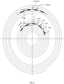
- One embodiment of such an encoder disc is schematically shown in FIG. 2 .
- One possible variation of the relative position of three spots on the data pattern surface of the encoder disc is shown in FIG. 3 (a figure identical to FIG. 2 on which the position of the three spots is shown).
- FIG. 1 illustrates an isometric plan view of a portion of a typical optical rotary encoder 100 according to an embodiment.
- the typical optical rotary encoder comprises an encoder disc 110 configured to be encoded.
- the encoder further comprises voice coil actuators 120 controlling an objective lens 130 tracking and focusing axes.
- the half mirror plate 140 reflects the input beam from the laser diode 170 passing through the diffraction grating 160, which generates the three beams out of it, towards the objective lens 130 that focuses the three beams on the encoder disc 110.
- the half mirror plate 140 also transmits the laser beam reflected back from the encoder disc 110 passing through the objective lens 130 towards the photodetector array IC 150.
- FIG. 2 demonstrates one possible disc spiral track layout.
- FIG. 3 represents the case of a three-beam method OPU (Optical Pick-Up), where the OPU three beams are projected on the disc along the disc radius.
- OPU Optical Pick-Up
- the spiral track patterns upon which the two flanking beams are projected are 'm' pitches (mp) apart from each other.
- the annotations of FIG. 2 and FIG. 3 represent the case where the track pattern layout corresponds to an encoder disc with n periods/cycles per revolution.
- the central beam of the three beams is projected on a disc grooves area where no data pattern is introduced, except for optional index signs, so that the focus and tracking error signals are not distorted as they might have been at low shaft encoder speeds in the case of focusing on tracks with a data pattern.
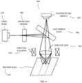
- FIG. 4 illustrates an isometric plan view of a portion of a typical optical linear encoder 400 according to another embodiment.
- the typical optical linear encoder comprises scaling grating 410 configured to be encoded.
- the encoder further comprises voice coil actuators 420 controlling an objective lens 430 tracking and focusing axes.
- the half mirror plate 440 reflects the input beam from the laser diode 470 passing through the diffraction grating 460, which generates the three beams out of it, towards the objective lens 430 that focuses the three beams on the encoder scale grating 410.
- the half mirror plate 440 also transmits the laser beam reflected back from the encoder scale grating 410 passing through the objective lens 430 towards the photodetector array IC 450.
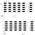
- FIG. 5 illustrates the tracks layout and the relative position of the three beam spots on the data pattern surface of an encoder linear scale according to an embodiment where ⁇ is the data track pattern period, p is the pitch between data pattern tracks and m is the number of data pattern track pitches distance between the three beam flanking beams.
- the three beams central beam of the embodiment is projected on free of data pattern tracks grooves region (except for possible index mark/marks as explained above and hereafter).
- the height difference between the pits and lands of the encoder phase grating disc/scale is one-quarter of the laser wavelength.
- the length of the pits and lands of the encoder disc spiral or linear scale track pattern should be slightly less than the focused spot size of the laser beam.
- the limited spiral pattern section width in the radial direction ensures that the above spot size relative to the pit length is maintained with the pit length variations as a function of the spiral radius required for keeping the encoder specified density (the number of cycles/periods per revolution).
- the design of the disc spiral track pattern layout may be such that the two flanking beams are projected on track's data patterns, which maintain a 1/4 cycle phase shift between each other. That is, the encoder quadrature type signals generated from the two flanking beams allow extracting of direction discrimination out of the quadrature signals.
- the disc design also allows maintaining the required specified encoder density/resolution, n, which is the number of cycles/periods per revolution.
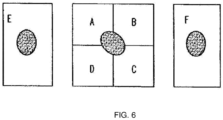
- the six segments (A, B, C, D, E, F) detector array of the well-known optical storage three beam method pick-up head includes two flanking elements (E and F), which receive the reflections generated by these skewed flanking beams is shown in FIG. 6 in connection with the use made of the three-beam method in various embodiments of the optical encoder disclosed herein.
- the radial position of the track relative to the main beam in the three-beam method may be determined using differential amplifiers which compare the level of illumination falling on each of the two flanking elements.
- error signals are generated and fed back to the tracking actuator magnetic coil which governs the radial position of the beam steering optics.
- Auxiliary tracking error information is also derived by evaluating the distribution of the illumination on the 4 central elements (A, B, C, D) of the photodetector array of FIG. 6 .
- the focus error signal which governs the pick-up head focus actuator, is also derived by evaluating the distribution of the main beam illumination on the 4 central elements (A, B, C, D) of the photo detector array.
- skewing the three beams is employed so the two flanking beams are over tracks, which their pattern is in quadrature phase shift (90 degrees out-of-phase) for extracting direction discrimination.
- the flanking beams skewing tracking technique described in the previous paragraph, cannot be implemented.
- the auxiliary tracking error information derived by evaluating the distribution of the main beam illumination on the 4 central elements of the photo detector is used, while the flanking beams are over tracks, which their pattern is in 90 degree out-of-phase, generating the quadrature signals for extracting direction discrimination.
- the encoder spiral pattern layout is such that the pits and lands are equal in length, up to the slight change with the track radius required to maintain the specified number of cycles per revolution. Designing the OPU diffraction grating is such that rotation in the appropriate angle will skew the two side beams in the appropriate angle to generate the desired quadrature signals for extraction of direction discrimination.
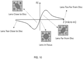
- the well-known astigmatic three beams method focus error (FE) for a typical arrangement of four quadrants detector is demonstrated herein in FIG. 10 in connection with the use made of the three-beam method in various embodiments of the optical encoder disclosed herein.
- the objective lens is astigmatic diagonally, giving the lens a different focal point along each diagonal.
- the spot on the detector is circular.
- the spot moves toward one or the other focal point, thus shortening the spot along one axis and lengthening it along the other, which creates an elliptical spot as is shown in FIG. 10 .
- the error is linear with distance close from the track, within a range of about 10 ⁇ m. Beyond this point, the reflected signal becomes diffuse and the FE signal goes back to zero.
- the spot is circular at focus and elliptical when away, while the focus-error signal is small in magnitude when the objective lens is far away from the disc or close to the disc as the reflected beam becomes diffuse and the FE signal goes back to zero.
- the FE signal can be supplemented with another signal measure to optimize focus position for the read processes.
- FIG. 11 illustrates measured focus error S-curves signals (FE) which may be employed in various embodiments.
- FIG. 7 illustrates the placement of groove, land, pits, and corresponding locations of the detectors as they may be positioned above the disc in the read head, including main detectors versus side detectors half a track away, as may be employed in various embodiments.
- the pits are placed at the center of the groove.
- the side detectors help measures more accurate tracking error signals.
- Each side detector can be either one detector (like the E and F detectors of FIG. 6 that are used in the most common case of the three-beam method and which may be used in various embodiments) or a set of two (as shown on FIG. 7 , which may be used in various embodiments) or four photo diode detectors (which may be used in various embodiments).
- the main detectors are placed to be receiving a signal substantially from the center of the tracks, while the side detectors are placed to be receiving a signal substantially from the center of the land, which is also called the half-track.
- This diagram shows three tracks.
- FIG. 8 and FIG. 9 show the tracking error (TE) signals of the well-known differential phase detect (DPD) and the differential push pull (DPP) methods, respectively, which may be used in various embodiments. These TE signals are calculated from the intensity reaching each quadrant of the main (central), e.g., four quadrant detector shown in FIG. 7 .
- DPD differential phase detect
- DPP differential push pull
- FIG. 8 shows the tracking error (TE) signal, based on differential phase detect (DPD) method, when sweeping the lens over tracks.
- the differential phase detector (DPD) requires data pits on the disc and is not applicable to a blank disc, since blank discs have no pits.
- the signals S1 and S2 plotted versus time are aligned; that is, the phase shift between the signals is zero.
- the detector deviates to the left or the right, a phase difference between the diagonal terms is present.
- the tracking error signal is capable of showing only the distance from the track center or half-track center. Sweeping the lens over tracks generates a tracking error signal that can be used to count the number of half-tracks.
- FIG. 9 shows the tracking error (TE) signal, based on differential push pull (DPP) method, when sweeping the lens over tracks.
- DPP differential push-pull
- the differential push-pull (DPP) which does not require that the disc contain data pits but instead relies on the difference in reflective properties between the region where data is supposed to be written, called the groove, and the remainder of the disc, that is, the land.
- the intensity of light received at the detectors on the left side is compared against the ones on the right side. With four detectors, this comparison is given by A + D - (B + C).
- the tracking error calculated in this method has a sinusoidal appearance.
- zero crossings can be used to count the number of half-tracks during a radial seek move, which represents the radial traveled distance.
- the measured radial traveled distance along with the required offsetting voltage to the tracking actuator and the tracking error signal information is used for compensating/reducing the encoder accuracy sensitivity to expansion with temperature shift as is explained later bellow.
- the dedicated beams and the photodetector cells for the tilt measurement may take the role of the flanking beams and the tracking photodetector cells E and F of the above well-known three beams pick-up method and be used as the reading photodetector cells of the quadrature signals.
- the encoder disc spiral quadrature data pattern section width is limited and the tilt effect at it is negligible and there is no need for the use of the tilt measurement in this case.
- the focus and tracking beams are projected on grooves area with no data pattern (except for index mark/marks as explained above and hereafter) on the disc/scale.
- the encoder head objective lens hits in some point the wall of the OPU reading head radial axis mechanical range end.
- the following embodiments are applicable engineering alternative solutions for preventing the head objective lens from hitting the radial tracking mechanical range end:
- Data pattern on the track, on which the focus beam is projected disturbs the focus performance when the encoder disc rotates at slow speeds, where the track pattern special frequencies fall within the focus actuator servo loop bandwidth.
- the embodiments include, for example:
- the OPU reading head degree of freedoms in the tracking and focus axes could farther be used in the optical encoders' field for improving the encoders' performances.
- the embodiment of implementing the optical encoder reading pick-up head with dynamic self-aligning auto focus eliminates the limitation ((1) above) and cost of maintaining the encoder scale stringent flatness/straightness requirements over a long encoder scale length (either the scale flatness/straightness itself or its assembled flatness/straightness). This keeps the scale within the reading pick-up head lens DOF along the whole scale length.
- the following techniques utilizing the unique pick-up head tracking axis degree of freedom for reducing the encoder accuracy sensitivity ((2) above) to expansion with temperature, may be implemented in the disclosed encoders:
- an adaptive focus servo loop bandwidth that is narrowed with the reduced encoder disc speed (as mentioned above) is implemented.
- This technique which ensures undisturbed focus servo loop performance at low encoder disc speed even when the focus beam is on a patterned data track, allows laying out a simpler encoder disc spiral pattern.
- the three beams are skewed so the two flanking beams are over tracks, which are in quadrature phase shift for extracting direction discrimination, with the adaptive focus servo loop bandwidth technique, it's possible to generate the quadrature (1/4 cycle phase shift) signals while aligning the three beams on the same track without skewing the beams and using the central four quadrature detector for both focusing and tacking. It's done by designing the OPU diffraction grating element, which generate the three beams, so that the two flanking beams projected on the encoder disc spiral track maintain a distance between each other of k ⁇ +3/4 ⁇ , where ⁇ is the period of one encoder cycle and k is an integer (0, 1, 2, 3).
- controlling the displacement distance between the satellite beam spots is implemented through the design and/or rotation of the diffraction grating element.
- the pits and lands are laid up on the spiral track in equal lengths ( ⁇ /2) up to the required slight incremental change in length as function of the disc radius in order to keep the desired specified encoder density, which is the number of cycles/periods per revolution of the encoder.
- multi-turn position encoders also measure multiple rotations or turns.
- an encoder disc spiral pattern layout may be utilized to implement a multi-turn type of encoder. More specifically, by employing a spiral type disc with unique indexing, e.g., for each turn of the spiral, for both measuring the encoder angular position per revolution and the number of encoder disc turns the functionality otherwise achieved by conventional multi-turn position encoders is achieved.
- the main beam is used to read the index and the flanking beams are used for the number of cycles per revolution as explained herein.
- An encoder disc for use in the disclosed laser encoder can be fabricated from a wafer by a lithographic technique. To improve the reflectivity of the wafer, a high reflectance metal layer, typically aluminum or gold could be used as a covering.
- the encoder disc can also be fabricated from glass.
- the most convenient way to fabricate the encoder disc is to utilize the state of the art optical storage like Compact Disc (CD), Digital Versatile Disc (DVD), and Blue Ray (BR) construction. This would make mass production easy and the cost would be very low.
- An improved modification of the optical storage production tools, like the ones of CD and DVD, etc., to support flexible encoder disc diameters will allow using the existing optical storage manufacturing tools while accommodating the desired flexibility of producing variety of encoder disc diameters of different optical encoder's production batches.
- a manufacturing flexibility of programming the tools jobs to producing series of discs of variable diameters and volumes is desirable.
- the optical storage OPU (Optical Pick-Up) objective lens is optimized by design to compensate the beam optical path towards the information layer within the disc PC (Poly Carbonate) layer.
- Existing conventional optical encoder discs with concentric data track pattern on their surface can also be read by the optical disc OPU utilizing the advantages of its additional dynamic degrees of freedom. It is possible to use the existing optical storage OPU objective lens as is for reading the current common used encoder scale/disc technology while introducing the necessary offset voltage to the objective lens focusing actuator.
- Using a modified optical storage OPU objective lens design without the above built in compensation for the optical path within the disc PC, which will be used for the existing conventional encoder disc, is also an alternative in which the above required offset voltage to the objective lens focusing actuator is unnecessary.
- the index track could be placed also in an inner radius to the AQB (A quad B; the A and B quadrature tracks that maintain 1/4 cycle/period phase shift between them) tracks, for example, as it is common in conventional encoder, and not only in between the AQB tracks: one flanking beam will read the outmost radius AQB track, the central beam will read the inner radius AQB track - using the central beam four quadrant sum signal and also will produce the focus error signal - and the other flanking beam will read the Index track.
- Another alternative is using glass CD/DVD/BR discs as the optical encoder disc if higher thermal stability with temperature shifts is desired. A glass plate of this kind is used in HDD (Hard Disc Drive), which is highly stable against heat.
- a glass encoder disc plate, on which multiple tracks of DVD-like pit marks, for example, are coded, is an existing process. Formation of pit marks tracks on a glass plate is an existing process, and it's done by plasma cutting machine. Glass CD/DVD discs are made this way today.
- the encoder quadrature pattern may be laid out on the disc in a way that provides multiple encoder resolutions on the same scale/disc unit. That is, for example, an encoder disc with multi-resolution encoder zones is achievable by changing the encoder resolution every predetermined number of pitches along the encoder disc spiral pattern. Such a disc may be implemented through the use of software to write the pattern on the disc. Positioning the OPU read head above the flexible desired encoder resolution zone is achieved by applying the appropriate offset voltage to the OPU read head objective lens tracking actuator or possibly moving the whole head towards the desired encoder density zone.
- the encoder electronics may use the existing optical storage drive chip set or part of it for processing and interpreting the encoder focusing, tracking and quadrature data, taking advantage of their low price because of their high production volumes for the optical storage market segment.
- the various embodiments disclosed herein can be implemented using hardware, firmware, software, or any combination thereof.
- the software is preferably implemented as an application program tangibly embodied on a program storage unit or computer readable medium consisting of parts, or of certain devices and/or a combination of devices.
- the application program may be uploaded to, and executed by, a machine comprising any suitable architecture.
- the machine is implemented on a computer platform having hardware such as one or more central processing units (“CPUs"), a memory, and input/output interfaces.
- CPUs central processing units
- the computer platform may also include an operating system and microinstruction code.
- a non-transitory computer readable medium is any computer readable medium except for a transitory propagating signal.
- Software shall be construed broadly to mean any type of instructions, whether referred to as software, firmware, middleware, microcode, hardware description language, or otherwise. Instructions may include code (e.g., in source code format, binary code format, executable code format, or any other suitable format of code).
Landscapes
- Physics & Mathematics (AREA)
- General Physics & Mathematics (AREA)
- Optics & Photonics (AREA)
- Chemical & Material Sciences (AREA)
- Engineering & Computer Science (AREA)
- Combustion & Propulsion (AREA)
- Optical Transform (AREA)
Claims (14)
- Optischer Encoder (100, 400), der Folgendes umfasst:ein Lichtfokussierungselement (130, 430);einen Lichtdetektor (150, 450), der zum Empfangen von Licht von einem Substrat (110, 410), das Positionsmarkierungen enthält, über das Lichtfokussierungselement (130, 430) und zum Umwandeln des empfangenen Lichts in wenigstens ein elektrisches Signal eingerichtet ist;einen Servomechanismus (120, 420), der eine Position des Lichtfokussierungselements (130, 430) basierend auf dem wenigstens einen elektrischen Signal anpasst; undeinen Prozessor, der das wenigstens eine elektrische Signal empfängt und zum Berichten einer Bewegung des Substrats (110, 410) basierend auf dem empfangenen wenigstens einen elektrischen Signal eingerichtet ist;wobei der optische Encoder (100, 400) ferner Folgendes umfasst:ein optisches Element (160, 460), das Licht, das von einer Lichtquelle stammt, in wenigstens einen zentralen Strahl und zwei flankierende Strahlen aufteilt, und wobei elektrische Repräsentationen einer Reflexion der flankierenden Strahlen von dem Substrat (110, 410) verwendet werden, um die berichtete Bewegung zu bestimmen; wobei die Bewegung eine Winkel- oder Linearentfernung ist, die durch das Substrat zurückgelegt wird;wobei der optische Encoder (100, 400) ferner dadurch gekennzeichnet ist, dass:
das Lichtfokussierungselement (130, 430) durch den Servomechanismus (120, 420) lateral mit Bezug auf das Substrat (110, 410) beweglich ist. - Optischer Encoder nach Anspruch 1, wobei das Lichtfokussierungselement durch den Servomechanismus zu dem Substrat hin oder von dem Substrat weg beweglich ist.
- Optischer Encoder nach Anspruch 1, wobei die Lichtquelle ein Laser ist.
- Optischer Encoder nach Anspruch 1, wobei das Substrat als eine Scheibe geformt ist und wobei die Positionsmarkierungen Lands (Flächen) und Pits (Gruben) sind, die in Spiralspuren angeordnet sind, zwischen denen Spiralhalbspur-Lands sind.
- Optischer Encoder nach Anspruch 1, wobei der Aktor den Fokus des Lichts anpasst, das an dem Lichtdetektor empfangen wird, indem die Position des Lichtfokussierungselements angepasst wird.
- Optischer Encoder nach Anspruch 1, der ferner Folgendes umfasst:eine Lichtquelle; undeine Halbspiegelplatte (140, 404), die Licht von der Lichtquelle zu dem Substrat reflektiert und von dem Substrat reflektiertes Licht zu dem Lichtdetektor durchlässt.
- Optischer Encoder nach Anspruch 1, wobei der Servomechanismus die Position des Lichtfokussierungselements aktiv als Reaktion auf Temperaturvariationen anpasst.
- Optischer Encoder nach Anspruch 1, wobei das Substrat ein Optische-Scheibe-Substrat ist.
- Optischer Encoder nach Anspruch 1, wobei das Lichtfokussierungselement aktiv durch den Servomechanismus positioniert wird, um beliebiges von Folgendem zu kompensieren: thermische Änderungen des Substrats und Ebenheitsvariationen des Substrats.
- Optischer Encoder nach Anspruch 1, wobei das Substrat mit beliebigem von Folgendem codiert ist: Informationen zum Bereitstellen einer absoluten Position, so dass der optische Encoder als ein Absolut-Encoder betreibbar ist, Informationen, die ein niederauflösendes Absolut-Encoder-Muster repräsentieren, das zur Verwendung beim Vornehmen von groben absoluten Messungen verwendbar ist, und Informationen, die ein hochauflösendes inkrementelles Encoder-Quadraturmuster zur Verwendung beim Vornehmen feiner Messungen repräsentieren, und Informationen, die ein grobes Absolut-Encoder-Muster zur Verwendung in einer Initialisierungsprozedur repräsentieren, und Informationen, die ein hochauflösendes inkrementelles Encoder-Quadraturmuster zur Verwendung beim Vornehmen von hochauflösenden Positionsmessungen repräsentieren.
- Optischer Encoder nach Anspruch 1, der ferner Folgendes umfasst: die Lichtquelle (170, 470).
- Optischer Encoder nach Anspruch 1, wobei eine elektrische Repräsentation einer Reflexion des zentralen Strahls verwendet wird, um eine ungestörte radiale Verfolgungsleistungsfähigkeit bereitzustellen, wenn der zentrale Strahl auf ein Substrat ohne einen Bereich von Datenmusterrillenspuren projiziert wird.
- Verfahren zur Verwendung durch einen optischen Encoder (100, 400), wobei der optische Encoder (100, 400) Folgendes umfasst:ein Lichtfokussierungselement (130, 430);einen Lichtdetektor (150, 450), der zum Empfangen von Licht von einem Substrat (110, 410), das Positionsmarkierungen enthält, über das Lichtfokussierungselement (130, 430) und zum Umwandeln des empfangenen Lichts in wenigstens ein elektrisches Signal eingerichtet ist;einen Servomechanismus (120, 420), der eine Position des Lichtfokussierungselements (130, 420) basierend auf dem wenigstens einen elektrischen Signal anpasst; undeinen Prozessor, der das wenigstens eine elektrische Signal empfängt und zum Berichten einer Bewegung des Substrats (110, 410) basierend auf dem empfangenen wenigstens einen elektrischen Signal eingerichtet ist;wobei das Verfahren ferner Folgendes umfasst:Aufteilen von Licht, das von einer Lichtquelle stammt, in wenigstens einen zentralen Strahl und zwei flankierende Strahlen;wobei elektrische Repräsentationen einer Reflexion der flankierenden Strahlen von dem Substrat (110, 410) verwendet werden, um die berichtete Bewegung zu bestimmen; wobei die Bewegung eine Winkel- oder Linearentfernung ist, die durch das Substrat zurückgelegt wird; und wobei das Lichtfokussierungselement (130, 430) durch den Servomechanismus (120, 420) lateral mit Bezug auf das Substrat (110, 410) bewegt wird.
- Verfahren nach Anspruch 13, ferner gekennzeichnet durch:
Verwenden einer elektrischen Repräsentation einer Reflexion des zentralen Strahls, um eine ungestörte Fokussierungsleistungsfähigkeit bereitzustellen, wenn der zentrale Strahl auf ein Substrat ohne einen Bereich von Datenmusterrillenspuren projiziert wird.
Applications Claiming Priority (2)
| Application Number | Priority Date | Filing Date | Title |
|---|---|---|---|
| US201662439714P | 2016-12-28 | 2016-12-28 | |
| PCT/US2017/068762 WO2018126039A1 (en) | 2016-12-28 | 2017-12-28 | Optical encoder system and method |
Publications (4)
| Publication Number | Publication Date |
|---|---|
| EP3563118A1 EP3563118A1 (de) | 2019-11-06 |
| EP3563118A4 EP3563118A4 (de) | 2020-07-08 |
| EP3563118B1 true EP3563118B1 (de) | 2024-10-16 |
| EP3563118C0 EP3563118C0 (de) | 2024-10-16 |
Family
ID=62710130
Family Applications (1)
| Application Number | Title | Priority Date | Filing Date |
|---|---|---|---|
| EP17887137.2A Active EP3563118B1 (de) | 2016-12-28 | 2017-12-28 | System und verfahren zur optischen codierung |
Country Status (3)
| Country | Link |
|---|---|
| US (2) | US10768022B2 (de) |
| EP (1) | EP3563118B1 (de) |
| WO (1) | WO2018126039A1 (de) |
Families Citing this family (3)
| Publication number | Priority date | Publication date | Assignee | Title |
|---|---|---|---|---|
| FR3111979B1 (fr) * | 2020-06-30 | 2023-03-24 | Codechamp | Revetement reflechissant des moyens de reflexion d’un codeur optique et codeur optique ainsi realise |
| CN114846301B (zh) * | 2020-12-01 | 2024-02-27 | 深圳市速腾聚创科技有限公司 | 光栅盘、z相信号的识别方法、光电编码器和激光雷达 |
| CN117213535A (zh) * | 2023-09-13 | 2023-12-12 | 传周半导体科技(上海)有限公司 | 一种反射式光学编码器芯片自适应封装 |
Family Cites Families (15)
| Publication number | Priority date | Publication date | Assignee | Title |
|---|---|---|---|---|
| US4162399A (en) * | 1977-09-16 | 1979-07-24 | Bei Electronics, Inc. | Optical encoder with fiber optics |
| FR2575578B1 (fr) * | 1984-12-31 | 1995-03-03 | Canon Kk | Appareil d'enregistrement et de reproduction optiques d'informations |
| JPS6310326A (ja) * | 1986-07-01 | 1988-01-16 | Sanyo Electric Co Ltd | 光ピツクアツプ装置 |
| US5107107A (en) | 1990-03-30 | 1992-04-21 | The United States Of America As Represented By The Administarator Of The National Aeronautics And Space Administration | Laser optical disk position encoder with active heads |
| US5825023A (en) * | 1997-03-26 | 1998-10-20 | The Hong Kong University Of Science & Technology | Auto focus laser encoder having three light beams and a reflective grating |
| US6646967B1 (en) * | 1997-08-12 | 2003-11-11 | Denon Digital Llc | Method for making copy protected optical discs |
| CN1167064C (zh) * | 1998-12-03 | 2004-09-15 | 株式会社三协精机制作所 | 激光头装置及光源单元 |
| US6975576B1 (en) * | 1999-07-13 | 2005-12-13 | Kabushiki Kaisha Toshiba | Optical head device and disk drive system having first and second light sources for emitting light beams of different wavelengths |
| GB0208048D0 (en) * | 2002-04-08 | 2002-05-22 | Digicliff Ltd | Optical controls |
| KR100536361B1 (ko) * | 2003-12-10 | 2005-12-12 | 삼성전기주식회사 | 광 픽업장치 |
| US20100157774A1 (en) * | 2008-12-23 | 2010-06-24 | General Electric Company | Data storage systems and methods |
| US8637804B2 (en) | 2009-12-10 | 2014-01-28 | Lockheed Martin Corporation | Rotary position encoder |
| JP5479255B2 (ja) * | 2010-07-20 | 2014-04-23 | キヤノン株式会社 | 光学式エンコーダ |
| CN104081459B (zh) * | 2012-01-06 | 2016-12-21 | 三菱电机株式会社 | 光学头装置及光盘装置 |
| WO2015145267A2 (en) * | 2014-02-26 | 2015-10-01 | Assa Abloy Ab | Laser encoder for small metallic patches and method of operating the same |
-
2017
- 2017-12-28 EP EP17887137.2A patent/EP3563118B1/de active Active
- 2017-12-28 WO PCT/US2017/068762 patent/WO2018126039A1/en not_active Ceased
-
2019
- 2019-03-01 US US16/290,394 patent/US10768022B2/en active Active
-
2020
- 2020-08-06 US US16/986,575 patent/US11156481B2/en active Active
Also Published As
| Publication number | Publication date |
|---|---|
| WO2018126039A1 (en) | 2018-07-05 |
| EP3563118A1 (de) | 2019-11-06 |
| US20190195662A1 (en) | 2019-06-27 |
| EP3563118C0 (de) | 2024-10-16 |
| US20200363240A1 (en) | 2020-11-19 |
| US10768022B2 (en) | 2020-09-08 |
| US11156481B2 (en) | 2021-10-26 |
| EP3563118A4 (de) | 2020-07-08 |
Similar Documents
| Publication | Publication Date | Title |
|---|---|---|
| US5107107A (en) | Laser optical disk position encoder with active heads | |
| CN101529211B (zh) | 采用具有公共刻线基板的多个子编码器的旋转光学编码器 | |
| US11156481B2 (en) | Optical encoder system and method | |
| KR100235912B1 (ko) | 정보기록매체, 트래킹 오차신호 검출장치, 정보기록장치 및 정보기록장치의 조정방법 | |
| JP2000055698A (ja) | 回転位置測定装置 | |
| US4987301A (en) | Reflective optical encoder device with light beams applied as spats spaced by 2 predetermined pitch | |
| US6873589B2 (en) | Method and device for detecting optical data and reading-writing apparatus for optical data | |
| US5602388A (en) | Absolute and directional encoder using optical disk | |
| US11874144B2 (en) | Displacement measurement system | |
| US5825023A (en) | Auto focus laser encoder having three light beams and a reflective grating | |
| US6151185A (en) | Position detecting apparatus, positioning apparatus, and information recording apparatus using the same | |
| KR100529986B1 (ko) | 광 집적화 유닛 및 이 유닛을 이용하는 광 픽업 장치와 광디스크 장치 | |
| US6829118B1 (en) | Optical rotational position information detecting apparatus | |
| US5274511A (en) | Servo signal recording method and apparatus | |
| JPH0843130A (ja) | 回転情報検出装置及び回転情報検出方法 | |
| US6191911B1 (en) | Positioning apparatus for hard disk servowriter | |
| WO2001013367A1 (en) | Method and apparatus for reading multiple tracks of an optical disk | |
| JPH01112110A (ja) | 光学式ロータリーエンコーダ | |
| JPH01112111A (ja) | 光学式ロータリーエンコーダ | |
| KR101055639B1 (ko) | 측정 시스템 | |
| JP2002071388A (ja) | 回折格子エンコーダ及び磁気ヘッドの位置決め装置 | |
| JPH1144507A (ja) | 回動物体の位置検出装置と位置決め装置及びそれを用いた情報記録装置 | |
| JPH07198422A (ja) | レーザエンコーダ | |
| US20110019519A1 (en) | Optical disc recording method and optical disc apparatus | |
| Zhou et al. | A positioning method for hard disk servowriter using an auto focus laser encoder |
Legal Events
| Date | Code | Title | Description |
|---|---|---|---|
| STAA | Information on the status of an ep patent application or granted ep patent |
Free format text: STATUS: THE INTERNATIONAL PUBLICATION HAS BEEN MADE |
|
| PUAI | Public reference made under article 153(3) epc to a published international application that has entered the european phase |
Free format text: ORIGINAL CODE: 0009012 |
|
| STAA | Information on the status of an ep patent application or granted ep patent |
Free format text: STATUS: REQUEST FOR EXAMINATION WAS MADE |
|
| 17P | Request for examination filed |
Effective date: 20190725 |
|
| AK | Designated contracting states |
Kind code of ref document: A1 Designated state(s): AL AT BE BG CH CY CZ DE DK EE ES FI FR GB GR HR HU IE IS IT LI LT LU LV MC MK MT NL NO PL PT RO RS SE SI SK SM TR |
|
| AX | Request for extension of the european patent |
Extension state: BA ME |
|
| DAV | Request for validation of the european patent (deleted) | ||
| DAX | Request for extension of the european patent (deleted) | ||
| A4 | Supplementary search report drawn up and despatched |
Effective date: 20200604 |
|
| RIC1 | Information provided on ipc code assigned before grant |
Ipc: G01M 15/06 20060101ALI20200529BHEP Ipc: G01D 5/38 20060101ALI20200529BHEP Ipc: G01D 5/347 20060101AFI20200529BHEP |
|
| STAA | Information on the status of an ep patent application or granted ep patent |
Free format text: STATUS: EXAMINATION IS IN PROGRESS |
|
| 17Q | First examination report despatched |
Effective date: 20210521 |
|
| GRAP | Despatch of communication of intention to grant a patent |
Free format text: ORIGINAL CODE: EPIDOSNIGR1 |
|
| STAA | Information on the status of an ep patent application or granted ep patent |
Free format text: STATUS: GRANT OF PATENT IS INTENDED |
|
| INTG | Intention to grant announced |
Effective date: 20240510 |
|
| GRAS | Grant fee paid |
Free format text: ORIGINAL CODE: EPIDOSNIGR3 |
|
| GRAA | (expected) grant |
Free format text: ORIGINAL CODE: 0009210 |
|
| STAA | Information on the status of an ep patent application or granted ep patent |
Free format text: STATUS: THE PATENT HAS BEEN GRANTED |
|
| AK | Designated contracting states |
Kind code of ref document: B1 Designated state(s): AL AT BE BG CH CY CZ DE DK EE ES FI FR GB GR HR HU IE IS IT LI LT LU LV MC MK MT NL NO PL PT RO RS SE SI SK SM TR |
|
| REG | Reference to a national code |
Ref country code: GB Ref legal event code: FG4D |
|
| REG | Reference to a national code |
Ref country code: CH Ref legal event code: EP |
|
| REG | Reference to a national code |
Ref country code: IE Ref legal event code: FG4D |
|
| REG | Reference to a national code |
Ref country code: DE Ref legal event code: R096 Ref document number: 602017085583 Country of ref document: DE |
|
| U01 | Request for unitary effect filed |
Effective date: 20241114 |
|
| U07 | Unitary effect registered |
Designated state(s): AT BE BG DE DK EE FI FR IT LT LU LV MT NL PT RO SE SI Effective date: 20241121 |
|
| U20 | Renewal fee for the european patent with unitary effect paid |
Year of fee payment: 8 Effective date: 20241227 |
|
| PG25 | Lapsed in a contracting state [announced via postgrant information from national office to epo] |
Ref country code: HR Free format text: LAPSE BECAUSE OF FAILURE TO SUBMIT A TRANSLATION OF THE DESCRIPTION OR TO PAY THE FEE WITHIN THE PRESCRIBED TIME-LIMIT Effective date: 20241016 Ref country code: IS Free format text: LAPSE BECAUSE OF FAILURE TO SUBMIT A TRANSLATION OF THE DESCRIPTION OR TO PAY THE FEE WITHIN THE PRESCRIBED TIME-LIMIT Effective date: 20250216 |
|
| PG25 | Lapsed in a contracting state [announced via postgrant information from national office to epo] |
Ref country code: ES Free format text: LAPSE BECAUSE OF FAILURE TO SUBMIT A TRANSLATION OF THE DESCRIPTION OR TO PAY THE FEE WITHIN THE PRESCRIBED TIME-LIMIT Effective date: 20241016 |
|
| PG25 | Lapsed in a contracting state [announced via postgrant information from national office to epo] |
Ref country code: NO Free format text: LAPSE BECAUSE OF FAILURE TO SUBMIT A TRANSLATION OF THE DESCRIPTION OR TO PAY THE FEE WITHIN THE PRESCRIBED TIME-LIMIT Effective date: 20250116 |
|
| PG25 | Lapsed in a contracting state [announced via postgrant information from national office to epo] |
Ref country code: GR Free format text: LAPSE BECAUSE OF FAILURE TO SUBMIT A TRANSLATION OF THE DESCRIPTION OR TO PAY THE FEE WITHIN THE PRESCRIBED TIME-LIMIT Effective date: 20250117 |
|
| PG25 | Lapsed in a contracting state [announced via postgrant information from national office to epo] |
Ref country code: PL Free format text: LAPSE BECAUSE OF FAILURE TO SUBMIT A TRANSLATION OF THE DESCRIPTION OR TO PAY THE FEE WITHIN THE PRESCRIBED TIME-LIMIT Effective date: 20241016 |
|
| PG25 | Lapsed in a contracting state [announced via postgrant information from national office to epo] |
Ref country code: RS Free format text: LAPSE BECAUSE OF FAILURE TO SUBMIT A TRANSLATION OF THE DESCRIPTION OR TO PAY THE FEE WITHIN THE PRESCRIBED TIME-LIMIT Effective date: 20250116 |
|
| PG25 | Lapsed in a contracting state [announced via postgrant information from national office to epo] |
Ref country code: SM Free format text: LAPSE BECAUSE OF FAILURE TO SUBMIT A TRANSLATION OF THE DESCRIPTION OR TO PAY THE FEE WITHIN THE PRESCRIBED TIME-LIMIT Effective date: 20241016 |
|
| PG25 | Lapsed in a contracting state [announced via postgrant information from national office to epo] |
Ref country code: MC Free format text: LAPSE BECAUSE OF FAILURE TO SUBMIT A TRANSLATION OF THE DESCRIPTION OR TO PAY THE FEE WITHIN THE PRESCRIBED TIME-LIMIT Effective date: 20241016 |
|
| PG25 | Lapsed in a contracting state [announced via postgrant information from national office to epo] |
Ref country code: SK Free format text: LAPSE BECAUSE OF FAILURE TO SUBMIT A TRANSLATION OF THE DESCRIPTION OR TO PAY THE FEE WITHIN THE PRESCRIBED TIME-LIMIT Effective date: 20241016 |
|
| PG25 | Lapsed in a contracting state [announced via postgrant information from national office to epo] |
Ref country code: CZ Free format text: LAPSE BECAUSE OF FAILURE TO SUBMIT A TRANSLATION OF THE DESCRIPTION OR TO PAY THE FEE WITHIN THE PRESCRIBED TIME-LIMIT Effective date: 20241016 |
|
| REG | Reference to a national code |
Ref country code: CH Ref legal event code: PL |
|
| PLBE | No opposition filed within time limit |
Free format text: ORIGINAL CODE: 0009261 |
|
| STAA | Information on the status of an ep patent application or granted ep patent |
Free format text: STATUS: NO OPPOSITION FILED WITHIN TIME LIMIT |
|
| 26N | No opposition filed |
Effective date: 20250717 |
|
| GBPC | Gb: european patent ceased through non-payment of renewal fee |
Effective date: 20250116 |
|
| PG25 | Lapsed in a contracting state [announced via postgrant information from national office to epo] |
Ref country code: GB Free format text: LAPSE BECAUSE OF NON-PAYMENT OF DUE FEES Effective date: 20250116 |
|
| PG25 | Lapsed in a contracting state [announced via postgrant information from national office to epo] |
Ref country code: CH Free format text: LAPSE BECAUSE OF NON-PAYMENT OF DUE FEES Effective date: 20241231 |
|
| PG25 | Lapsed in a contracting state [announced via postgrant information from national office to epo] |
Ref country code: IE Free format text: LAPSE BECAUSE OF NON-PAYMENT OF DUE FEES Effective date: 20241228 |