EP1801290B1 - Verfahren und anlage zum aufbringen partikelförmiger feststoffe auf ein substrat - Google Patents
Verfahren und anlage zum aufbringen partikelförmiger feststoffe auf ein substrat Download PDFInfo
- Publication number
- EP1801290B1 EP1801290B1 EP06025677.3A EP06025677A EP1801290B1 EP 1801290 B1 EP1801290 B1 EP 1801290B1 EP 06025677 A EP06025677 A EP 06025677A EP 1801290 B1 EP1801290 B1 EP 1801290B1
- Authority
- EP
- European Patent Office
- Prior art keywords
- particulate solids
- nozzle
- synthetic resin
- resin layer
- wood
- Prior art date
- Legal status (The legal status is an assumption and is not a legal conclusion. Google has not performed a legal analysis and makes no representation as to the accuracy of the status listed.)
- Not-in-force
Links
Images


Classifications
-
- E—FIXED CONSTRUCTIONS
- E04—BUILDING
- E04C—STRUCTURAL ELEMENTS; BUILDING MATERIALS
- E04C2/00—Building elements of relatively thin form for the construction of parts of buildings, e.g. sheet materials, slabs, or panels
- E04C2/02—Building elements of relatively thin form for the construction of parts of buildings, e.g. sheet materials, slabs, or panels characterised by specified materials
- E04C2/26—Building elements of relatively thin form for the construction of parts of buildings, e.g. sheet materials, slabs, or panels characterised by specified materials composed of materials covered by two or more of groups E04C2/04, E04C2/08, E04C2/10 or of materials covered by one of these groups with a material not specified in one of the groups
-
- B—PERFORMING OPERATIONS; TRANSPORTING
- B05—SPRAYING OR ATOMISING IN GENERAL; APPLYING FLUENT MATERIALS TO SURFACES, IN GENERAL
- B05B—SPRAYING APPARATUS; ATOMISING APPARATUS; NOZZLES
- B05B7/00—Spraying apparatus for discharge of liquids or other fluent materials from two or more sources, e.g. of liquid and air, of powder and gas
- B05B7/14—Spraying apparatus for discharge of liquids or other fluent materials from two or more sources, e.g. of liquid and air, of powder and gas designed for spraying particulate materials
- B05B7/1404—Arrangements for supplying particulate material
-
- B—PERFORMING OPERATIONS; TRANSPORTING
- B05—SPRAYING OR ATOMISING IN GENERAL; APPLYING FLUENT MATERIALS TO SURFACES, IN GENERAL
- B05B—SPRAYING APPARATUS; ATOMISING APPARATUS; NOZZLES
- B05B7/00—Spraying apparatus for discharge of liquids or other fluent materials from two or more sources, e.g. of liquid and air, of powder and gas
- B05B7/14—Spraying apparatus for discharge of liquids or other fluent materials from two or more sources, e.g. of liquid and air, of powder and gas designed for spraying particulate materials
- B05B7/1404—Arrangements for supplying particulate material
- B05B7/1454—Arrangements for supplying particulate material comprising means for supplying collected oversprayed particulate material
-
- B—PERFORMING OPERATIONS; TRANSPORTING
- B05—SPRAYING OR ATOMISING IN GENERAL; APPLYING FLUENT MATERIALS TO SURFACES, IN GENERAL
- B05B—SPRAYING APPARATUS; ATOMISING APPARATUS; NOZZLES
- B05B7/00—Spraying apparatus for discharge of liquids or other fluent materials from two or more sources, e.g. of liquid and air, of powder and gas
- B05B7/14—Spraying apparatus for discharge of liquids or other fluent materials from two or more sources, e.g. of liquid and air, of powder and gas designed for spraying particulate materials
- B05B7/1404—Arrangements for supplying particulate material
- B05B7/1472—Powder extracted from a powder container in a direction substantially opposite to gravity by a suction device dipped into the powder
-
- D—TEXTILES; PAPER
- D21—PAPER-MAKING; PRODUCTION OF CELLULOSE
- D21H—PULP COMPOSITIONS; PREPARATION THEREOF NOT COVERED BY SUBCLASSES D21C OR D21D; IMPREGNATING OR COATING OF PAPER; TREATMENT OF FINISHED PAPER NOT COVERED BY CLASS B31 OR SUBCLASS D21G; PAPER NOT OTHERWISE PROVIDED FOR
- D21H23/00—Processes or apparatus for adding material to the pulp or to the paper
- D21H23/02—Processes or apparatus for adding material to the pulp or to the paper characterised by the manner in which substances are added
- D21H23/22—Addition to the formed paper
- D21H23/50—Spraying or projecting
-
- E—FIXED CONSTRUCTIONS
- E04—BUILDING
- E04C—STRUCTURAL ELEMENTS; BUILDING MATERIALS
- E04C2/00—Building elements of relatively thin form for the construction of parts of buildings, e.g. sheet materials, slabs, or panels
- E04C2/02—Building elements of relatively thin form for the construction of parts of buildings, e.g. sheet materials, slabs, or panels characterised by specified materials
- E04C2/10—Building elements of relatively thin form for the construction of parts of buildings, e.g. sheet materials, slabs, or panels characterised by specified materials of wood, fibres, chips, vegetable stems, or the like; of plastics; of foamed products
- E04C2/12—Building elements of relatively thin form for the construction of parts of buildings, e.g. sheet materials, slabs, or panels characterised by specified materials of wood, fibres, chips, vegetable stems, or the like; of plastics; of foamed products of solid wood
-
- E—FIXED CONSTRUCTIONS
- E04—BUILDING
- E04C—STRUCTURAL ELEMENTS; BUILDING MATERIALS
- E04C2/00—Building elements of relatively thin form for the construction of parts of buildings, e.g. sheet materials, slabs, or panels
- E04C2/02—Building elements of relatively thin form for the construction of parts of buildings, e.g. sheet materials, slabs, or panels characterised by specified materials
- E04C2/10—Building elements of relatively thin form for the construction of parts of buildings, e.g. sheet materials, slabs, or panels characterised by specified materials of wood, fibres, chips, vegetable stems, or the like; of plastics; of foamed products
- E04C2/16—Building elements of relatively thin form for the construction of parts of buildings, e.g. sheet materials, slabs, or panels characterised by specified materials of wood, fibres, chips, vegetable stems, or the like; of plastics; of foamed products of fibres, chips, vegetable stems, or the like
-
- B—PERFORMING OPERATIONS; TRANSPORTING
- B05—SPRAYING OR ATOMISING IN GENERAL; APPLYING FLUENT MATERIALS TO SURFACES, IN GENERAL
- B05B—SPRAYING APPARATUS; ATOMISING APPARATUS; NOZZLES
- B05B13/00—Machines or plants for applying liquids or other fluent materials to surfaces of objects or other work by spraying, not covered by groups B05B1/00 - B05B11/00
- B05B13/02—Means for supporting work; Arrangement or mounting of spray heads; Adaptation or arrangement of means for feeding work
- B05B13/0221—Means for supporting work; Arrangement or mounting of spray heads; Adaptation or arrangement of means for feeding work characterised by the means for moving or conveying the objects or other work, e.g. conveyor belts
-
- B—PERFORMING OPERATIONS; TRANSPORTING
- B05—SPRAYING OR ATOMISING IN GENERAL; APPLYING FLUENT MATERIALS TO SURFACES, IN GENERAL
- B05B—SPRAYING APPARATUS; ATOMISING APPARATUS; NOZZLES
- B05B7/00—Spraying apparatus for discharge of liquids or other fluent materials from two or more sources, e.g. of liquid and air, of powder and gas
- B05B7/14—Spraying apparatus for discharge of liquids or other fluent materials from two or more sources, e.g. of liquid and air, of powder and gas designed for spraying particulate materials
- B05B7/1481—Spray pistols or apparatus for discharging particulate material
- B05B7/1486—Spray pistols or apparatus for discharging particulate material for spraying particulate material in dry state
-
- D—TEXTILES; PAPER
- D21—PAPER-MAKING; PRODUCTION OF CELLULOSE
- D21H—PULP COMPOSITIONS; PREPARATION THEREOF NOT COVERED BY SUBCLASSES D21C OR D21D; IMPREGNATING OR COATING OF PAPER; TREATMENT OF FINISHED PAPER NOT COVERED BY CLASS B31 OR SUBCLASS D21G; PAPER NOT OTHERWISE PROVIDED FOR
- D21H19/00—Coated paper; Coating material
- D21H19/36—Coatings with pigments
-
- D—TEXTILES; PAPER
- D21—PAPER-MAKING; PRODUCTION OF CELLULOSE
- D21H—PULP COMPOSITIONS; PREPARATION THEREOF NOT COVERED BY SUBCLASSES D21C OR D21D; IMPREGNATING OR COATING OF PAPER; TREATMENT OF FINISHED PAPER NOT COVERED BY CLASS B31 OR SUBCLASS D21G; PAPER NOT OTHERWISE PROVIDED FOR
- D21H27/00—Special paper not otherwise provided for, e.g. made by multi-step processes
- D21H27/18—Paper- or board-based structures for surface covering
- D21H27/22—Structures being applied on the surface by special manufacturing processes, e.g. in presses
- D21H27/26—Structures being applied on the surface by special manufacturing processes, e.g. in presses characterised by the overlay sheet or the top layers of the structures
- D21H27/28—Structures being applied on the surface by special manufacturing processes, e.g. in presses characterised by the overlay sheet or the top layers of the structures treated to obtain specific resistance properties, e.g. against wear or weather
-
- Y—GENERAL TAGGING OF NEW TECHNOLOGICAL DEVELOPMENTS; GENERAL TAGGING OF CROSS-SECTIONAL TECHNOLOGIES SPANNING OVER SEVERAL SECTIONS OF THE IPC; TECHNICAL SUBJECTS COVERED BY FORMER USPC CROSS-REFERENCE ART COLLECTIONS [XRACs] AND DIGESTS
- Y10—TECHNICAL SUBJECTS COVERED BY FORMER USPC
- Y10T—TECHNICAL SUBJECTS COVERED BY FORMER US CLASSIFICATION
- Y10T156/00—Adhesive bonding and miscellaneous chemical manufacture
- Y10T156/10—Methods of surface bonding and/or assembly therefor
- Y10T156/1089—Methods of surface bonding and/or assembly therefor of discrete laminae to single face of additional lamina
-
- Y—GENERAL TAGGING OF NEW TECHNOLOGICAL DEVELOPMENTS; GENERAL TAGGING OF CROSS-SECTIONAL TECHNOLOGIES SPANNING OVER SEVERAL SECTIONS OF THE IPC; TECHNICAL SUBJECTS COVERED BY FORMER USPC CROSS-REFERENCE ART COLLECTIONS [XRACs] AND DIGESTS
- Y10—TECHNICAL SUBJECTS COVERED BY FORMER USPC
- Y10T—TECHNICAL SUBJECTS COVERED BY FORMER US CLASSIFICATION
- Y10T428/00—Stock material or miscellaneous articles
- Y10T428/25—Web or sheet containing structurally defined element or component and including a second component containing structurally defined particles
-
- Y—GENERAL TAGGING OF NEW TECHNOLOGICAL DEVELOPMENTS; GENERAL TAGGING OF CROSS-SECTIONAL TECHNOLOGIES SPANNING OVER SEVERAL SECTIONS OF THE IPC; TECHNICAL SUBJECTS COVERED BY FORMER USPC CROSS-REFERENCE ART COLLECTIONS [XRACs] AND DIGESTS
- Y10—TECHNICAL SUBJECTS COVERED BY FORMER USPC
- Y10T—TECHNICAL SUBJECTS COVERED BY FORMER US CLASSIFICATION
- Y10T428/00—Stock material or miscellaneous articles
- Y10T428/25—Web or sheet containing structurally defined element or component and including a second component containing structurally defined particles
- Y10T428/252—Glass or ceramic [i.e., fired or glazed clay, cement, etc.] [porcelain, quartz, etc.]
-
- Y—GENERAL TAGGING OF NEW TECHNOLOGICAL DEVELOPMENTS; GENERAL TAGGING OF CROSS-SECTIONAL TECHNOLOGIES SPANNING OVER SEVERAL SECTIONS OF THE IPC; TECHNICAL SUBJECTS COVERED BY FORMER USPC CROSS-REFERENCE ART COLLECTIONS [XRACs] AND DIGESTS
- Y10—TECHNICAL SUBJECTS COVERED BY FORMER USPC
- Y10T—TECHNICAL SUBJECTS COVERED BY FORMER US CLASSIFICATION
- Y10T428/00—Stock material or miscellaneous articles
- Y10T428/27—Web or sheet containing structurally defined element or component, the element or component having a specified weight per unit area [e.g., gms/sq cm, lbs/sq ft, etc.]
- Y10T428/273—Web or sheet containing structurally defined element or component, the element or component having a specified weight per unit area [e.g., gms/sq cm, lbs/sq ft, etc.] of coating
- Y10T428/277—Cellulosic substrate
-
- Y—GENERAL TAGGING OF NEW TECHNOLOGICAL DEVELOPMENTS; GENERAL TAGGING OF CROSS-SECTIONAL TECHNOLOGIES SPANNING OVER SEVERAL SECTIONS OF THE IPC; TECHNICAL SUBJECTS COVERED BY FORMER USPC CROSS-REFERENCE ART COLLECTIONS [XRACs] AND DIGESTS
- Y10—TECHNICAL SUBJECTS COVERED BY FORMER USPC
- Y10T—TECHNICAL SUBJECTS COVERED BY FORMER US CLASSIFICATION
- Y10T428/00—Stock material or miscellaneous articles
- Y10T428/29—Coated or structually defined flake, particle, cell, strand, strand portion, rod, filament, macroscopic fiber or mass thereof
- Y10T428/2982—Particulate matter [e.g., sphere, flake, etc.]
-
- Y—GENERAL TAGGING OF NEW TECHNOLOGICAL DEVELOPMENTS; GENERAL TAGGING OF CROSS-SECTIONAL TECHNOLOGIES SPANNING OVER SEVERAL SECTIONS OF THE IPC; TECHNICAL SUBJECTS COVERED BY FORMER USPC CROSS-REFERENCE ART COLLECTIONS [XRACs] AND DIGESTS
- Y10—TECHNICAL SUBJECTS COVERED BY FORMER USPC
- Y10T—TECHNICAL SUBJECTS COVERED BY FORMER US CLASSIFICATION
- Y10T428/00—Stock material or miscellaneous articles
- Y10T428/29—Coated or structually defined flake, particle, cell, strand, strand portion, rod, filament, macroscopic fiber or mass thereof
- Y10T428/2982—Particulate matter [e.g., sphere, flake, etc.]
- Y10T428/2991—Coated
-
- Y—GENERAL TAGGING OF NEW TECHNOLOGICAL DEVELOPMENTS; GENERAL TAGGING OF CROSS-SECTIONAL TECHNOLOGIES SPANNING OVER SEVERAL SECTIONS OF THE IPC; TECHNICAL SUBJECTS COVERED BY FORMER USPC CROSS-REFERENCE ART COLLECTIONS [XRACs] AND DIGESTS
- Y10—TECHNICAL SUBJECTS COVERED BY FORMER USPC
- Y10T—TECHNICAL SUBJECTS COVERED BY FORMER US CLASSIFICATION
- Y10T428/00—Stock material or miscellaneous articles
- Y10T428/29—Coated or structually defined flake, particle, cell, strand, strand portion, rod, filament, macroscopic fiber or mass thereof
- Y10T428/2982—Particulate matter [e.g., sphere, flake, etc.]
- Y10T428/2991—Coated
- Y10T428/2998—Coated including synthetic resin or polymer
Definitions
- the invention relates to a method and a system for introducing particulate solids into a substrate.
- a substrate mainly papers, especially carrier papers or decor papers, but especially plates and panels made of plastic, wood or wood material are referred to below, which are used on ceiling, wall or floor.
- the application of particulate solids is particularly interesting when thin layers of particulate solids are to be applied to a substrate.
- the particulate solids are relatively heavy and hard. They have a specific gravity of more than 2 g / cm 3 , usually more than 3 g / cm 3 .
- the Mohs hardness is 8-10.
- the typical application for the present invention is the application of corundum, silicates or other particulate solids to a substrate to improve its surface properties.
- the application of corundum improves the abrasion resistance of resin layers and surface coatings built therefrom.
- the essential requirement here is that the particulate solids do not form the surface of the substrate. They must be embedded in a near-surface layer to B. to achieve improved abrasion resistance. In synthetic resin layers interspersed silicates improve z. B. the scratch resistance of surface coatings.
- the disadvantage here is that the preparation and processing of the dispersion is very complex, because settling of the particulate solids must be avoided. Even in the case of brief interruptions of production, the application device must be completely cleaned, as otherwise the dispersion will add lines and nozzles. The order volume also fluctuates to a relatively high degree.
- the beats WO 2005/042644 to scatter such particulate solids onto the substrate.
- a roller arrangement under which the substrate is passed, particulate solids are scattered onto the substrate.
- This arrangement is mechanically easy to manufacture and operate, but the uniformity and accuracy of the job is not satisfactory and the mechanical wear is very high.
- very expensive fibers have to be applied to the surface of the substrate and aligned in a targeted manner in order to ensure the embedding of the particulate solids.
- DE 40 37 650 shows an apparatus in which a ceramic article is coated with synthetic resin.
- the solution according to the invention provides a device which is designed for spraying particulate solids on a substrate which is coated with a moist and / or tacky synthetic resin layer, with a conduit at the first end of which means for generating gas pressure are arranged and their second end having a free orifice further comprising a particulate matter reservoir and provided with a nozzle for generating a pressure differential, the reservoir and the nozzle being inserted into the conduit such that, in the operating condition, the pressure differential created by the nozzle particulate solids are transferred from the reservoir into the conduit and fluidized, which are then transported to the free mouth of the conduit from which the particulate solids then exit and are sprayed into the moist and / or tacky synthetic resin layer.
- a preferred embodiment of the device according to the invention provides that a Venturi nozzle is inserted into the conduit. It creates a negative pressure in the pipe.
- the Venturi nozzle is inserted into the line of the device according to the invention in that it draws the particulate matter from the reservoir into the line by the negative pressure it generates, where the particles are swirled and entrained in the gas stream until they are always still homogeneous gas-solid mixture impinge on the moist and / or sticky synthetic resin layer of the substrate, where the solid particles are deposited as a very uniform layer and sink into the wet resin layer.
- the particulate solids are fluidized in the operating state in the reservoir. They are preferably traversed by air or other inert gas and are kept in this way in the reservoir in motion.
- the device according to claim 1 is provided with at least one spray nozzle on the mouth.
- the spray nozzle makes it possible to control the coating of the substrate very precisely.
- the shape of the spray cone can be adjusted as desired in order to achieve a predetermined spray result on the substrate.
- the shape of the spray nozzle for example, also depends on whether the mouth of the line is stationary or movable (we will discuss this below).
- a wide range of nozzles or nozzle openings can be used for the device according to the invention, for example nozzles with an annular opening or nozzles with a slot-shaped opening.
- nozzles can communicate with the mouth of the pipe via a manifold, without affecting the uniformity of the spraying process.
- a plurality of devices according to the invention can be arranged in parallel, which are each equipped with one or more nozzles.
- the nozzles are adjustable according to a further advantageous embodiment about their longitudinal and or transverse axes.
- the lines of the device according to the invention can be selected depending on the application. They can be fixed pipes (pipes) or flexible pipes (hoses). Hoses are particularly advantageous when the mouth of the second end or possibly arranged thereon spray nozzle are designed to be movable. Lines and spray nozzles, but also the distributor can be made according to a preferred embodiment of the invention made of plastic.
- the device is thus assembled in a cost effective manner from lightweight components. It is also possible to combine components made of different materials. So z. B. the lines are each made in sections of metal and plastic. Also ceramic components can be used for the preparation of the aforementioned lines, spray nozzles or manifolds.
- the device according to the invention also has means for conveying the substrate.
- the substrate can simply be placed on the conveyor or fixed there. It is then passed under the stationary or movable mouth or spray nozzle of the device and coated with the particulate solid.
- the substrate can be fixed on the means for conveying, be it by negative pressure, be it z. B. by oppositely arranged rollers or conveyor belts. The provision of such conveying means enables the industrial-economical coating of the solid solid particle substrate.
- the device according to the invention can indeed certainly be used for itself.
- the device is preferably integrated in a system for surface coating.
- the application of synthetic resin or the painting of wood-based surfaces is usually carried out in impregnation or painting at working speeds of about 30 m / min to about 100 m / min, often between 40 m / min and 60 m / min.
- the spray device according to the invention can be readily integrated into these systems.
- the compact design of the device proves to be very beneficial.
- conveying means are frequently provided which transport the substrates to be processed or coated through all stations of the complex coating installations.
- particulate solids in the apparatus according to claim 1. Often corundum is used, but it is also conceivable the use of silicates, carbides or diamond dust.
- the particulate solids having a specific gravity of more than 2 g / cm 3 , often more than 3 g / cm 3 are usually used in diameters of 30 to 100 .mu.m, preferably in diameters of 40 .mu.m to 60 .mu.m. They are made by spraying or in the resin layers on the surface of carrier or decor papers but also embedded in resin layers directly on the surface of wood-based materials to improve the surface coating properties, typically to increase abrasion resistance or scratch resistance.
- the moist and / or tacky synthetic resin layer when spraying or spraying the particulate solids has a layer thickness which has at least half the average diameter of the particulate solids, ie, layer thicknesses of 15 .mu.m to 50 .mu.m.
- layer thicknesses 15 .mu.m to 50 .mu.m.
- a further synthetic resin layer is also applied after the spraying process in order to complete the embedding of the particulate solids.
- the device according to the invention a high uniformity of the application of solid particles is achieved, which is clearly superior to the previously known methods.
- the uniformity of the particle application is important in several respects: on the one hand, an increasing application of solids adversely affects the transparency of the substrate surface. On the other hand, if there are high fluctuations in the uniformity of the order, significant safety measures must be taken when applying solid particles, if specified quantities are to be observed. This adversely affects the cost and leads to increased wear on application devices.
- the solid particles can with an accuracy of up to ⁇ 0.8 g / m 2, preferably to be scattered to ⁇ 0.5 g / m 2 onto the substrate.
- the order accuracy is even more narrow and according to the invention is up to ⁇ 0.3 g / m 2 .
- a job accuracy of up to ⁇ 0.1 g / m 2 is achieved.
- the achievable distribution accuracy is greater than ⁇ 2 g / m 2 .
- the solution according to the invention therefore offers considerable economic and technical advantages.
- the device according to the invention offers, according to an advantageous embodiment, various possibilities for individually setting the order of the particulate solids.
- the distance to the surface can also be changed.
- the movement of the free orifice relative to the substrate is matched to the feed rate of the conveying means, which transport the substrate through the device according to the invention.
- the device according to the invention can also be adapted to the respective substrate by the number of the spray nozzle. For example, groups of nozzles may be connected via manifolds to the mouth of the conduit to achieve a predetermined spread pattern.
- the application of the particulate solids can be adapted to a large extent to the substrate to be sprayed in a wide range.
- Application methods known from the prior art do not allow such an individual adjustment of application quantity and distribution of the particulate solids.
- the device according to the invention is designed according to a preferred embodiment so that further means for modifying, in particular for coating the particulate solids in the line are provided.
- the modifying may be a coating, for example to impart better binding to the particulate solids on the substrate or to impart improved optical properties to the particulate solids.
- the solid particles z. B. silanized to achieve better adhesion to the substrate.
- the means for modifying are inserted into the conduit between the reservoir and the mouth, the modifying agent is sprayed into the conduit or, preferably, in the same manner as the particulate solids by a pressure change in the conduit entrained and then clad the particulate solids.
- the inventive device further allows due to the high accuracy in applying the particulate solids and applying varying amounts, ie a precise differentiation between areas where solid is applied to the substrate and areas where less, more or no solid on the substrate is applied. Substrates with discrete sections of varying amounts of particulate solids can be produced.
- particulate solids are sprayed into a synthetic resin layer with a moist and / or tacky surface of a substrate.
- the spraying of such a moist and / or tacky resin-coated substrate with particulate solids allows for very uniform coating of the substrate.
- it can be a substrate that has not yet reacted, or a substrate coated with paint or varnish.
- it can also be a decorative paper soaked with not yet dried melamine resin. Embedding the sprayed particulate solids in the moist and / or tacky surface of the substrate requires much less use of such wet and / or tacky coating agents than conventional processes, eg, those which apply the solid particles in the form of dispersions.
- the subsequent drying or curing of the moist and / or sticky coating additionally contributes to the fixation of the particulate solids. It is essential that the particulate solids penetrate as deeply as possible into the synthetic resin layer. They should not rest on the synthetic resin layer but be embedded in this layer.
- Solid particles which do not penetrate into the synthetic resin layer or which do not adhere to the surface of the substrate can be returned to the reservoir via a suction system and subsequent sighting. If the process according to the invention is carried out in a manner in which the particulate solids do not penetrate deeply into the synthetic resin layer and are accordingly not completely enclosed by the synthetic resin, then it is advisable to subsequently apply at least one layer of synthetic resin containing the still exposed portions of the particulate Encloses solids.
- the inventive method is implemented in the apparatus according to the invention described above. It is simple and straightforward in technical application, in particular it is insensitive to downtime.
- the special requirement of the deep penetration of the particulate solids in the resin layer is perfectly implemented.
- the relatively high specific gravity of the particulate solids in conjunction with the air flow causes a sufficiently deep penetration into the resin layer.
- the gas pressure is built up by simple means, for example by a pump or by means of a connection to a centrally installed compressed air line.
- the change from the higher to the reduced pressure is expediently brought about by a nozzle, preferably by a Venturi nozzle.
- the particles are removed from the reservoir due to entrained by the nozzle pressure drop in the line, about the principle of operation of the water jet pump.
- the spray cone for the solid to be sprayed onto the substrate is predetermined by a spray nozzle placed on the mouth of the pipe.
- the spray cone can-as described above in the description of the device according to the invention-be adapted to the individual requirements of the respective substrate by optimizing the type and orientation of the spray nozzle. The optimization of the spray nozzle is carried out by practical experiments.
- the spray nozzle can be designed so that the substrate is sprayed intermittently. There are then sections of the substrate z. B. web-shaped or in transverse stripes sprinkled with solid solids. For example, portions of a wall, ceiling or floor panel are sprinkled only where a particulate surface is also desired. There, where z. B. pitch saws after the scattering of the solid particles to set to separate the panels, a disturbing, wear on the saw causing coating with particulate solids can be omitted or at least significantly reduced.
- the aforementioned application rates of up to 100 g / m 2 and in particular the accuracy of the coating with up to 0.8 g / m 2 , preferably up to 0.1 g / m 2 can by tuning between gas flow, nozzle geometry, in particular the scattering nozzle and speed of the substrate moved relative to the device, but also by increasing or decreasing the distance between the substrate and the spray nozzle. It is within the usual scope to optimize such devices to achieve the optimum setting of these parameters, tailored to the particular application.
- the invention relates to a particularly uniformly coated with solid particles substrate, wherein the particulate solid is introduced into a synthetic resin layer.
- substrates particularly decorative papers and panels, can be provided that are within close tolerances with particulate solids are coated.
- the tolerance for the order quantity of the particulate solids amounts to a simple embodiment of the invention up to ⁇ 0.8 g / m 2 , according to a preferred embodiment, the tolerance is up to ⁇ 0.5 g / m 2 , more preferably up to ⁇ 0.3 g / m 2 , advantageously up to ⁇ 0.1 g / m 2 .
- the uniform layer distribution allows specified for the respective substrate abrasion, z. B. to achieve a certain abrasion resistance, with an overall lower use of solid particles to achieve than previously possible.
- the thus coated substrate is part of a multilayer surface coating.
- the synthetic resin layer according to the invention which is coated particularly uniformly with corundum, is covered by a further synthetic resin layer.
- Fig. 1 shows a device 2 for spraying particulate solids.
- the device 2 has a line 4, the first end 6 is connected to a here schematically indicated by "D" compressed air line.
- the line 4 (here with a line cross section of 6 mm) and thus also the Venturi nozzle is acted upon via the compressed air line D with an air flow volume of 1.5 m 3 / h.
- the second end, the free mouth 8 of the conduit 4 is provided with a spray nozzle 10.
- the line 4 passes through a reservoir 12 containing particulate corundum.
- the corundum has a specific gravity of 4 g / cm 3 .
- a Venturi nozzle 14 is inserted into the conduit 4. By the negative pressure generated in the venturi nozzle 14 in the operating state is via a suction line 16 corundum sucked from the reservoir 12 under swirling in the line.
- the delivery air flow is 6 bar.
- the container 12 is open to the environment, it is refilled regularly in accordance with the consumption of corundum.
- the line 4 is mainly made of stainless steel. However, it has a section 4a, which is made of flexible plastic. At least in areas where plastic components are used, the system is earthed to avoid static electricity. Due to the flexible plastic conduit 4a, the free mouth 8 can be aligned with the nozzle 10 attached thereto at exactly the desired distance from the substrate to be coated.
- the corundum K has an average diameter of 60 microns.
- the corundum K is sprayed from the nozzle 10 onto the surface of the substrate 18.
- the substrate 18, here a high-density fiberboard (HDF board) is coated with a moist and sticky, not yet cured layer 20 of melamine resin (layer thickness 50 microns).
- the spray cone 11 of the spray nozzle 10 is in Fig. 1 indicated; it extends over the entire width of the HDF plate 18.
- the substrate 18 is passed over conveying means, which are indicated as a roller 22, under the spray nozzle 10 at a speed of 60 m / min.
- corundum K is sprayed with a distribution accuracy of 0.5 g / m 2 .
- the corundum particles sink almost completely into the melamine resin layer 20.
- the melamine resin layer is dried. Since the corundum particles and the melamine resin have approximately equal refractive indices, a transparent layer is produced.
- An overlay paper with a sheet weight of 30 g / m 2 and a web width of 210 cm is filled with liquid melamine resin in a squeegee-type impregnation unit.
- the applied amount of melamine resin is about 120 g / m 2 .
- the solids content of the melamine resin is 50%.
- the impregnated overlay paper is referred to below as impregnate.
- 20 g / m 2 of corundum powder (particle size 40 ⁇ m) are sprayed onto the impregnate on the top side of the moist impregnate using a spray device which has twelve spray heads of a width of 210 cm.
- the spraying devices correspond to those in Fig. 1 illustrated device.
- the web speed of the impregnate under the twelve fixed spray heads is about 80 m / min.
- the corundum powder is applied with a distribution accuracy of 0.5 g / m 2 on the surface of the impregnate.
- the corundum powder applied to the impregnate sinks into the melamine resin layer.
- the corundum powder is completely enveloped by the melamine resin.
- the measured after drying thickness of the melamine resin corundum layer is about 100 microns. The extensive, if possible complete enveloping of the corundum powder by the melamine resin is a prerequisite for the desired here transparent coating.
- the corundum-containing overlay paper is dried in a floating dryer to a residual moisture of 16 to 18% by weight, based on the dry content of the impregnate. Subsequently, an additional melamine layer of 30 g / m 2 to 40 g / m 2 is applied with a raster coater on the underside of the impregnate. When passing through further dryer zones of the suspended bed dryer, a residual moisture of from 6% by weight to 7% by weight of the impregnate is set.
- the corundum-containing substrate is turned over and pressed onto a high-density fiberboard (HDF board) in combination with melamine resin-impregnated decor paper.
- HDF board high-density fiberboard
- the resulting panel can be used as a high-quality surface for laminate flooring in the abrasion class AC 4.
- An HDF plate is first decorated in direct printing in three-color printing on the top decorative. Subsequently, a melamine resin layer of 60 g / m 2 is applied with a roller coater. In the still liquid melamine resin 15 g / m 2 of corundum powder (particle size: 60 microns) with an in Fig. 1 sprayed schematically illustrated device.
- the melamine coating with the corundum powder embedded therein is pre-dried in a hot-air dryer until the surface coating has a residual moisture content of about 15% by weight based on this. Subsequently, another protective layer of cellulose fibers and melamine resin is applied and this surface structure is precondensed with hot air so far that it is tack-free, but the melamine resin is not yet crosslinked.
- the printed and coated with corundum plate is in a short-cycle press (16 sec. At 160 ° C at the plate surface, 3 N / mm 2 ) pressed.
- a melamine film is placed on the underside of the HDF plate in return, which ensures that the underside of the plate is protected, and that the plate is flat.
- the finished panel is suitable as a panel for the decoration of walls, ceilings or floors.
- FIGS Fig. 2 . 3 the same components as in Fig. 1 ,
- the container 12, which receives the corundum K, is provided with an air bottom 24. Through the air bottom 24, the container 12 is flowed through from its lower region by air, which fluidizes the corundum.
- the injector 26 supplies one or more lines 4, through which the fluidized corundum is conveyed to the spray nozzles 10.
- the pressure in the delivery lines is usually 0.2 to 4 bar, usually 1 to 3.5 bar.
- the line or lines 4 open into a nozzle 28, the more nozzles 10, which are arranged distributed over the width of the substrate 18.
- the nozzle assembly 28 distributes the fluidized corundum K to the nozzles 10 via distributor lines 4b arranged in the nozzle assembly 28.
- the nozzle assembly 28 is freely adjustable in height above the substrate. Within the nozzle block 28, the nozzles 10 are freely adjustable about their axes.
- the nozzle 28 is surrounded by a housing 30 which in Fig. 2 is indicated.
- a suction 32 is connected to the housing 30.
- the suction unit 32 sucks the conveying air emerging from the nozzles 10 via the suction line 34.
- the air flow of the suction air is A in Fig. 2 indicated. This avoids unwanted turbulence over the substrate.
- the housing 30 is open to the environment, preferably approximately at the level of the substrate 18. Thus, external air F can be sucked in to compensate for the pressure.
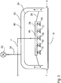
- Fig. 3 shows a preferred embodiment of the spray and suction device.
- an inner hood 36 is inserted into the housing 30.
- a cover plate 38 closes off the side wall of the nozzle block 28 to the inner hood 36.
- a suction channel 40 which is flowed through by the suction air A and possibly sucked external air F.
- the fan 32 generates through the suction line 34 this air flow.
Landscapes
- Engineering & Computer Science (AREA)
- Architecture (AREA)
- Life Sciences & Earth Sciences (AREA)
- Wood Science & Technology (AREA)
- Civil Engineering (AREA)
- Structural Engineering (AREA)
- Application Of Or Painting With Fluid Materials (AREA)
Description
- Die Erfindung betrifft ein Verfahren und eine Anlage zum Einbringen partikelförmiger Feststoffe in ein Substrat.
- Als Substrat werden nachfolgend vor allem Papiere, insbesondere Trägerpapiere oder Dekorpapiere, vor allem aber auch Platten und Paneele aus Kunststoff, Holz oder Holzwerkstoff bezeichnet, die an Decke, Wand oder Boden eingesetzt werden.
- Das Auftragen von partikelförmigen Feststoffen ist insbesondere dann interessant, wenn dünne Schichten partikelförmiger Feststoffe auf ein Substrat aufgetragen werden sollen. Die partikelförmigen Feststoffe sind relativ schwer und hart. Sie weisen ein spezifisches Gewicht von mehr als 2 g/cm3, meist von mehr als 3 g/cm3 auf. Die Mohs-Härte beträgt 8-10. Der typische Anwendungsfall für die vorliegende Erfindung ist das Aufbringen von Korund, von Silikaten oder von anderen partikelförmigen Feststoffen auf ein Substrat, um dessen Oberflächeneigenschaften zu verbessern. Beispielsweise wird durch Auftragen von Korund die Abriebfestigkeit von Kunstharzschichten und daraus aufgebaute Oberflächenbeschichtungen verbessert. Wesentliche Vorgabe dabei ist es, dass die partikelförmigen Feststoffe nicht die Oberfläche des Substrats bilden. Sie müssen in eine oberflächennahe Schicht eingebettet sein, um z. B. eine verbesserte Abriebfestigkeit zu erreichen. In Kunstharzschichten eingestreute Silikate verbessern z. B. die Kratzbeständigkeit von Oberflächenbeschichtungen.
- Für das Auftragen solcher partikelförmigen Feststoffe sind verschiedene technische Lösungen bekannt. Eine Gruppe von Vorschlägen stellt darauf ab, die partikelförmigen Feststoffe von vornherein in Flüssigkeiten einzubinden und diese Aufzuwalzen, Aufzugießen oder Aufzustreichen. Beispielsweise beschreibt die
WO 00/44984 WO 93/17182 DE 196 04 907 oder dieDE 195 08 797 eine Dispersion enthaltend partikelförmige Feststoffe. Diese Dispersion wird durch eine Spüldüse von unten auf das jeweils zu beschichtende Substrat aufgetragen. Weiter wird vorgeschlagen, solchen Dispersionen Zuschlagstoffe zuzusetzen, die die partikelförmigen Feststoffe besser handhabbar machen. Als Zuschlagstoffe werden Fasern und/oder sphärische Körper (Glaskugeln) vorgeschlagen. Nachteilig ist hier, dass die Herstellung und Verarbeitung der Dispersion sehr aufwändig ist, weil ein Absetzen der partikelförmigen Feststoffe vermieden werden muss. Auch bei kurzzeitigen Unterbrechungen der Produktion muss die Auftragsvorrichtung vollständig gereinigt werden, da die Dispersion ansonsten Leitungen und Düsen zusetzt. Die Auftragsmenge schwankt zudem in verhältnismäßig hohem Maße. - Alternativ schlägt die
WO 2005/042644 vor, solche partikelförmigen Feststoffe auf das Substrat zu streuen. Über eine Walzenanordnung, unter der das Substrat vorbeigeführt wird, werden partikelförmige Feststoffe auf das Substrat gestreut. Diese Anordnung ist mechanisch einfach herzustellen und zu betreiben, allerdings ist die Gleichmäßigkeit und Genauigkeit des Auftrags nicht zufrieden stellend und der mechanische Verschleiß ist sehr hoch. Zudem müssen in einem zweiten Schritt sehr aufwändig Fasern auf die Oberfläche des Substrats aufgebracht und gezielt ausgerichtet werden, um das Einbetten der partikelförmigen Feststoffe zu gewährleisten. -
DE 40 37 650 zeigt eine Vorrichtung, bei der ein Keramikgegenstand mit Kunstharz beschichtet wird. - Sämtliche Lösungen müssen sich damit auseinandersetzen, dass die partikelförmigen Feststoffe wie Korund, Silikate oder andere Partikel meist sehr abrasiv sind. Die Verfahren, die aus dem Stand der Technik bekannt sind, versuchen daher, den Kontakt zwischen den partikelförmigen Feststoffen und den jeweiligen Fördervorrichtungen so schonend wie möglich zu gestalten, um den Abrieb an den Fördervorrichtungen zu minimieren. Das in der Praxis äußerst aufwändige Einbetten der partikelförmigen Feststoffe in Kunstharz verhüllt die Partikel wirkungsvoll. Das Streuen über eine Walzenanordnung vermeidet nach Möglichkeit störende Reibung.
- Es ist daher Aufgabe der Erfindung, eine Vorrichtung, ein Verfahren und eine Holzwerkstoffplatte bereitzustellen, bei der partikelförmige Feststoffe wirtschaftlich in ein Substrat und in eine Oberflächenbeschichtung eingebettet werden können. Diese Aufgabe wird gelöst durch eine Vorrichtung nach Anspruch 1, ein Verfahren nach Anspruch 13 und eine Holzwerkstoffplatte nach Anspruch 18.
- Die erfindungsgemäße Lösung sieht eine Vorrichtung vor, die zum Sprühen von partikelförmigen Feststoffen auf ein Substrat, das mit einer feuchten und/oder klebrigen Kunstharzschicht überzogen ist, ausgelegt ist, mit einer Leitung, an deren erstem Ende Mittel zum Erzeugen von Gasdruck angeordnet sind und deren zweites Ende eine freie Mündung aufweist, die weiter einen Vorratsbehälter für partikelförmige Feststoffe aufweist und die mit einer Düse zum Erzeugen eines Druckunterschieds ausgestattet ist, wobei der Vorratsbehälter und die Düse so in die Leitung eingefügt sind, dass im Betriebszustand durch den von der Düse erzeugten Druckunterschied partikelförmige Feststoffe aus dem Vorratsbehälter in die Leitung überführt und verwirbelt werden, die dann bis zur freien Mündung der Leitung transportiert werden, aus der die partikelförmigen Feststoffe dann austreten und in die feuchte und/oder klebrige Kunstharzschicht gesprüht werden.
- Versuche haben ergeben, dass - entgegen der bisherigen Auffassung der Fachleute - ein Sprühen von partikelförmigen Feststoffen auf ein Substrat - und damit ein Einsprühen der Partikel in die feuchte und/oder klebrige Kunstharzschicht - ohne Weiteres möglich ist. Der Verschleiß an der Vorrichtung ist erstaunlich gering, insbesondere wenn die Feststoff-Partikel ausreichend verwirbelt sind. Die erfindungsgemäße Vorrichtung erfordert zum Sprühen der partikelförmigen Feststoffe kaum bewegte Bauteile, was die für die industrielle Anwendung sehr vorteilhaft ist. Dadurch, dass allein die Feststoff-Partikel gesprüht werden, wird eine besonders genaue Verteilung der partikelförmigen Feststoffe erreicht.
- Die Verwirbelung, die durch die Druckdifferenz unter den Feststoff-Partikeln erzeugt wird, ist wesentliche Voraussetzung für ein gleichmäßiges Sprühen des partikelförmigen Feststoffs. Eine bevorzugte Ausführung der erfindungsgemäßen Vorrichtung sieht vor, dass eine Venturi-Düse in die Leitung eingesetzt wird. Sie erzeugt einen Unterdruck in der Leitung. Die Venturi-Düse ist so in die Leitung der erfindungsgemäßen Vorrichtung eingesetzt, dass sie durch den Unterdruck, den sie erzeugt, den partikelförmigen Feststoff aus dem Vorratsbehälter mit in die Leitung reißt, wo die Partikel verwirbelt werden und im Gasstrom mitgeführt werden bis sie als immer noch homogenes Gas-Feststoff-Gemisch auf der feuchten und/oder klebrigen Kunstharzschicht des Substrats auftreffen, wo die Feststoff-Partikel als sehr gleichmäßige Schicht abgelagert werden und in die feuchte Kunstharz-Schicht einsinken. Nach einer weiter bevorzugten Ausführungsform der erfindungsgemäßen Vorrichtung sind die partikelförmigen Feststoffe im Betriebszustand in dem Vorratsbehälter fluidisiert. Sie sind vorzugsweise von Luft oder einem anderen Inertgas durchströmt und werden auf diese Weise im Vorratsbehälter in Bewegung gehalten.
- Erfindungsgemäß ist die Vorrichtung nach Anspruch 1 mit mindestens einer Sprühdüse auf der Mündung versehen. Die Sprühdüse ermöglicht es, die Beschichtung des Substrats sehr genau zu steuern. Es kann -je nach Wahl der Düse- die Form des Sprühkegels wunschgemäß eingestellt werden, um ein vorgegebenes Sprühergebnis auf dem Substrat zu erreichen. Die Form der Sprühdüse richtet sich beispielsweise auch danach ob die Mündung der Leitung ortsfest oder beweglich angeordnet ist (hierauf gehen wir weiter unten ein). Ein breites Spektrum von Düsen bzw. Düsenöffnungen kann für die erfindungsgemäße Vorrichtung eingesetzt werden, beispielsweise Düsen mit kreisringförmiger Öffnung oder Düsen mit schlitzförmiger Öffnung. Um breitere Substrate z. B. Holzwerkstoffplatten zu beschichten, ist es auch möglich, mehrere Sprühdüsen nebeneinander anzuordnen. Mehrere Sprühdüsen können über einen Verteiler mit der Mündung der Leitung in Verbindung stehen, ohne dass die Gleichmäßigkeit des Sprühvorgangs beeinträchtigt wird. Dabei können mehrere erfindungsgemäße Vorrichtungen parallel angeordnet sein, die jeweils mit einer oder mehreren Düsen ausgestattet sind. Die Düsen sind nach einer weiter vorteilhaften Ausführung um ihre Längs- und oder Querachsen einstellbar.
- Die Leitungen der erfindungsgemäßen Vorrichtung können je nach Anwendungsfall gewählt werden. Es können feste Leitungen (Rohre) oder flexible Leitungen (Schläuche) sein. Schläuche sind insbesondere dann von Vorteil, wenn die Mündung des zweiten Endes bzw. die daran ggf. angeordnete Sprühdüse beweglich ausgelegt sind. Leitungen und Sprühdüsen, aber auch die Verteiler können nach einer bevorzugten Ausführungsform der Erfindung aus Kunststoff hergestellt sein. Die Vorrichtung ist damit in kostengünstiger Weise aus leichten Bauteilen zusammengestellt. Es können auch Bauteile aus unterschiedlichen Werkstoffen kombiniert werden. So können z. B. die Leitungen jeweils abschnittsweise aus Metall und aus Kunststoff hergestellt sein. Auch Keramikbauteile können zur Herstellung der vorerwähnten Leitungen, Sprühdüsen oder Verteiler eingesetzt sein.
- Es wird bevorzugt, wenn die erfindungsgemäße Vorrichtung auch Mittel zum Fördern des Substrats aufweist. Das Substrat kann -je nach dem ob es sich um ein Dekorpapier, Furnier oder eine Holzwerkstoffoberfläche handelt- einfach auf die Fördermittel aufgelegt oder dort fixiert werden. Es wird dann unter der ortsfesten oder beweglichen Mündung bzw. Sprühdüse der Vorrichtung vorbeigeführt und mit dem partikelförmigen Feststoff beschichtet. Falls erforderlich kann das Substrat auf den Mitteln zum Fördern fixiert werden, sei es durch Unterdruck, sei es z. B. durch einander gegenüberliegend angeordnete Walzen oder Förderbänder. Das Vorsehen von solchen Mitteln zum Fördern ermöglicht die industriell wirtschaftliche Beschichtung des Substrats mit festen Feststoff-Partikeln.
- Es wird als besonderer Vorteil der Erfindung angesehen, dass die erfindungsgemäße Vorrichtung zwar durchaus auch für sich genutzt werden kann. Bevorzugt ist die Vorrichtung aber in eine Anlage zur Oberflächenbeschichtung integriert. Das Auftragen von Kunstharz oder das Lackieren von Holzwerkstoffoberflächen erfolgt üblicherweise in Imprägnieranlagen oder Lackieranlagen bei Arbeitsgeschwindigkeiten von ca. 30 m/min bis ca. 100 m/min, oft zwischen 40 m/min und 60 m/min. Bei diesen Arbeitsgeschwindigkeiten kann die erfindungsgemäße Sprühvorrichtung ohne weiteres in diese Anlagen integriert werden. Hier erweist sich die kompakte Bauform der Vorrichtung als sehr vorteilhaft. Bei integrierten Vorrichtungen sind häufig Fördermittel vorgesehen, die die zu bearbeitenden bzw. zu beschichtenden Substrate durch sämtliche Stationen der komplexen Beschichtungsanlagen transportieren.
- Es kann erfindungsgemäß eine große Bandbreite von partikelförmigen Feststoffen in der Vorrichtung nach Anspruch 1 verarbeitet werden. Häufig wird Korund eingesetzt, denkbar ist aber auch der Einsatz von Silikaten, Karbiden oder Diamantstaub. Die partikelförmigen Feststoffe mit einem spezifischen Gewicht von mehr als 2 g/cm3, oft von mehr als 3 g/cm3, werden üblicherweise in Durchmessern von 30 bis 100 µm, bevorzugt in Durchmessern von 40 µm bis 60 µm eingesetzt. Sie werden durch das Auf- bzw. Einsprühen in Kunstharz-Schichten auf der Oberfläche von Träger- oder Dekorpapieren aber auch in Kunstharz-Schichten direkt auf der Oberfläche von Holzwerkstoffen eingebettet, um die Eigenschaften der Oberflächenbeschichtung zu verbessern, typischerweise zur Steigerung der Abriebfestigkeit oder der Kratzfestigkeit. Es wird bevorzugt, dass die feuchte und/oder klebrige Kunstharzschicht beim Auf- bzw. Einsprühen der partikelförmigen Feststoffe eine Schichtstärke aufweist, die mindestens die Hälfte des durchschnittlichen Durchmessers der partikelförmigen Feststoffe aufweist, also beispielsweise Schichtstärken von 15 µm bis 50 µm. Beim Einsprühen der Partikel werden diese erfindungsgemäß durch Verdrängung des Kunstharzes dann weitgehend von dem Kunstharz umhüllt. Erfindungsgemäß wird nach dem Sprühvorgang auch noch eine weitere Kunstharzschicht aufgebracht, um das Einbetten der partikelförmigen Feststoffe zu vervollständigen.
- Mit der erfindungsgemäßen Vorrichtung können nahezu beliebige Mengen von Feststoff-Partikeln auf das Substrat aufgebracht werden. Erstaunlich ist, dass Versuche ergeben haben, dass auch geringe Mengen von partikelförmigen Feststoffen zuverlässig und gleichmäßig aufgetragen werden können. Mengen von bis zu 100 g/m2, bevorzugt von bis zu 80 g/m2, besonders bevorzugt von bis zu 50 g/m2, vorteilhaft von bis zu 30 g/m2 können mittels der erfindungsgemäßen Vorrichtung mit hoher Gleichmäßigkeit auf das Substrat aufgetragen werden, und das - wie vorstehend erwähnt- bei hoher Arbeitsgeschwindigkeit.
- Als besonders vorteilhaft wird angesehen, dass mit der erfindungsgemäßen Vorrichtung eine hohe Gleichmäßigkeit des Auftrags an Feststoff-Partikeln erreicht wird, die den bisher bekannten Verfahren deutlich überlegen ist. Die Gleichmäßigkeit des Partikel-Auftrags ist in mehrfacher Hinsicht von Bedeutung: zum einen beeinflusst ein steigender Feststoff-Auftrag die Transparenz der Substrat-Oberfläche nachteilig. Zum anderen müssen bei hohen Schwankungen in der Gleichmäßigkeit des Auftrags erhebliche Sicherheits-Mengen beim Auftrag von Feststoff-Partikeln vorgesehen werden, wenn festgelegte Auftragmengen einzuhalten sind. Dies beeinflusst die Kosten nachteilig und führt zu erhöhtem Verschleiß an Auftrags-Vorrichtungen.
- Erfindungsgemäß können die Feststoff-Partikel mit einer Genauigkeit von bis zu ± 0,8 g/m2, bevorzugt von bis zu ± 0,5 g/m2 auf das Substrat gestreut werden. Besonders bevorzugt ist die Auftrags-Genauigkeit noch enger gefasst und liegt erfindungsgemäß bei bis zu ± 0,3 g/m2. Vorteilhaft wird eine Auftrags-Genauigkeit von bis zu ± 0,1 g/m2 erreicht. Bei bekannten Verfahren liegt die erreichbare Verteilgenauigkeit bei über ± 2 g/m2. Die erfindungsgemäße Lösung bietet demgegenüber also erhebliche wirtschaftliche und technische Vorteile.
- Die erfindungsgemäße Vorrichtung bietet nach einer vorteilhaften Ausführung verschiedene Möglichkeiten, den Auftrag der partikelförmigen Feststoffe individuell einzustellen. So kann die freie Mündung der Leitung, ggf. mit der aufgesetzten Sprühdüse, sowohl parallel zur Ebene des zu beschichtenden Substrats beweglich angeordnet sein, beispielsweise auf einer Schiene über dem zu beschichtenden Substrat verfahrbar sein. Alternativ oder zusätzlich kann auch der Abstand zur Oberfläche verändert werden. Die Bewegung der freien Mündung relativ zum Substrat ist auf die Vorschubgeschwindigkeit der Fördermittel abgestimmt, die das Substrat durch die erfindungsgemäße Vorrichtung transportieren. Alternativ kann die erfindungsgemäße Vorrichtung auch durch die Anzahl der Sprühdüse an das jeweilige Substrat angepasst werden. Beispielsweise können Gruppen von Düsen über Verteiler an die Mündung der Leitung angeschlossen werden, um ein vorgegebenes Streubild zu erzielen. Durch diese vielfältigen Einstellmöglichkeiten kann der Auftrag der partikelförmigen Feststoffe in weiten Bereichen individuell auf das zu besprühende Substrat angepasst sein. Auftragsverfahren, die aus dem Stand der Technik bekannt sind, ermöglichen eine derart individuelle Einstellung von Auftragsmenge und Verteilung der partikelförmigen Feststoffe nicht.
- Die erfindungsgemäße Vorrichtung ist nach einer bevorzugten Ausführung so ausgebildet, dass weitere Mittel zum Modifizieren, insbesondere zum Beschichten der partikelförmigen Feststoffe in der Leitung vorgesehen sind. Das Modifizieren kann ein Beschichten sein, beispielsweise um den partikelförmigen Feststoffen eine bessere Bindung auf dem Substrat zu verleihen oder um den partikelförmigen Feststoffen verbesserte optische Eigenschaften zu verleihen. Häufig werden die Feststoff-Partikel z. B. silanisiert, um eine bessere Haftung auf dem Substrat zu erreichen. Die Mittel zum Modifizieren werden in die Leitung zwischen Vorratsbehälter und Mündung eingesetzt, das Mittel zum Modifizieren wird in die Leitung eingesprüht oder -was bevorzugt wird- auf die gleiche Weise wie die partikelförmigen Feststoffe durch einen Druckwechsel in die Leitung hineingerissen und umkleiden dann die partikelförmigen Feststoffe.
- Die erfindungsgemäße Vorrichtung ermöglicht weiter aufgrund der hohen Genauigkeit beim Aufbringen der partikelförmigen Feststoffe auch ein Aufbringen wechselnder Mengen, also ein präzises Differenzieren zwischen Bereichen, in denen Feststoff auf das Substrat aufgebracht wird und Bereichen, in denen weniger, mehr oder gar kein Feststoff auf das Substrat aufgebracht wird. Es können Substrate mit diskreten Abschnitten unterschiedlicher Mengen an partikelförmigen Feststoffen erzeugt werden.
- Das erfindungsgemäße Verfahren sieht vor, dass partikelförmige Feststoffe in eine feuchte und/ oder klebrige Kunstharzschicht eines Substrat gesprüht werden mit den Schritten:
- Beschichten des Substrats mit einer feuchten und/oder klebrigen Kunstharzschicht
- Aufbauen von Gasdruck in einer Leitung
- Erzeugen eines Druckwechsels in der Leitung
- Verwirbeln und Mitreißen von partikelförmigen Feststoffen mit einem spezifischen Gewicht von mehr als 2 g/cm3 in die Leitung
- Einsprühen von verwirbelten, partikelförmigen Feststoffen aus der Leitung in die feuchte und/oder klebrige Kunstharzschicht des Substrats.
- Erfindungsgemäß ist vorgesehen, dass in eine Kunstharz-Schicht mit feuchter und/oder klebriger Oberfläche eines Substrats partikelförmige Feststoffe eingesprüht werden. Das Einsprühen eines solchen feuchten und/oder klebrigen mit Kunstharz beschichteten Substrats mit partikelförmigen Feststoffen ermöglicht die sehr gleichmäßige Beschichtung des Substrats. Typischerweise kann es sich um ein mit noch nicht ausreagiertem Kunstharz versehenes Substrat oder um ein mit Farbe oder Lack beschichtetes Substrat handeln. Es kann aber auch ein Dekorpapier sein, das mit noch nicht getrocknetem Melaminharz getränkt ist. Das Einbetten der aufgesprühten partikelförmigen Feststoffe in die feuchte und/oder klebrige Oberfläche des Substrats erfordert einen sehr viel geringeren Einsatz solcher feuchten und/oder klebrigen Beschichtungsmittel als herkömmliche Verfahren, z.B. solche, die die Feststoff-Partikel in Form von Dispersionen auftragen. Das nachfolgende Trocknen oder Aushärten der feuchten und/oder klebrigen Beschichtung trägt zusätzlich zur Fixierung der partikelförmigen Feststoffe bei. Wesentlich ist, dass die partikelförmigen Feststoffe möglichst tief in die Kunstharzschicht eindringen. Sie sollen nicht auf der Kunstharzschicht aufliegen sondern in diese Schicht eingebettet sein.
- Es hat sich als vorteilhaft erwiesen, die feuchte und/oder klebrige Kunstharzschicht nach dem Einbringen der partikelförmigen Feststoffe zu trocknen oder auszuhärten. Üblicherweise erfolgt dies in einem Trockner oder Ofen, den das beschichtete Substrat durchläuft.
- Es wird erfindungsgemäß angestrebt, den aufgesprühten partikelförmigen Feststoff möglichst vollständig in die Kunstharzschicht einzubringen. Feststoff-Partikel, die nicht in die Kunstharzschicht eindringen oder die nicht auf der Oberfläche des Substrats haften, können über eine Absauganlage und nachfolgende Sichtung zurück in den Vorratsbehälter überführt werden. Wird das erfindungsgemäße Verfahren auf eine Weise durchgeführt, bei dem die partikelförmigen Feststoffe nicht tief in die Kunstharzschicht eindringen und dementsprechend nicht vollständig von dem Kunstharz umschlossen werden, so empfiehlt es sich, anschließend mindestens eine Schicht eines Kunstharzes aufzubringen, die die noch freiliegenden Abschnitte der partikelförmigen Feststoffe umschließt.
- Das erfindungsgemäße Verfahren wird in der vorstehend beschriebenen erfindungsgemäßen Vorrichtung umgesetzt. Es ist einfach und unkompliziert in der technischen Anwendung, insbesondere ist es gegenüber Stillständen unempfindlich. Die besondere Anforderung des tiefen Eindringens der partikelförmigen Feststoffe in die Kunstharzschicht wird ausgezeichnet umgesetzt. Das verhältnismäßig hohe spezifische Gewicht der partikelförmigen Feststoffe bewirkt in Verbindung mit dem Luftstrom ein genügend tiefes Eindringen in die Kunstharzschicht.
- Der Gasdruck wird mit einfachen Mitteln, beispielsweise durch eine Pumpe oder mittels eines Anschlusses an eine zentral verlegte Druckluftleitung aufgebaut. Der Wechsel vom höheren zum reduzierten Druck wird zweckmäßig durch eine Düse, bevorzugt durch eine Venturi-Düse herbeigeführt. Die Partikel werden aus dem Vorratsbehälter infolge des durch die Düse erzeugten Druckabfalls in der Leitung mitgerissen, etwa nach dem Funktionsprinzip der Wasserstrahlpumpe.
- Nach einer weiteren vorteilhaften Ausführung des erfindungsgemäßen Verfahrens wird der Sprühkegel für den auf das Substrat aufzusprühenden Feststoff durch eine auf die Mündung der Leitung aufgesetzte Sprühdüse vorgegeben. Der Sprühkegel kann -wie vorstehend bei der Beschreibung der erfindungsgemäßen Vorrichtung beschrieben- an die individuellen Anforderungen des jeweiligen Substrats angepasst werden, indem die Art und die Ausrichtung der Sprühdüse optimiert wird. Die Optimierung der Sprühdüse erfolgt durch praktische Versuche.
- So kann beispielsweise die Sprühdüse so ausgelegt sein, dass das Substrat intermittierend besprüht wird. Es werden dann Abschnitte des Substrats z. B. bahnenförmig oder in quer liegenden Streifen mit festem Feststoff bestreut. Beispielsweise werden Abschnitte eines Wand-, Decken- oder Fußbodenpaneels nur dort bestreut, wo eine mit partikelförmigen Feststoffen versehene Oberfläche auch erwünscht ist. Dort, wo z. B. Aufteilsägen nach dem Streuen der Feststoff-Partikel ansetzen, um die Paneele zu vereinzeln, kann eine störende, Verschleiß an den Sägen verursachende Beschichtung mit partikelförmigen Feststoffen unterbleiben oder zumindest erheblich reduziert werden.
- Die vorgenannten Auftragsmengen von bis zu 100 g/m2 und insbesondere auch die Genauigkeit der Beschichtung mit bis zu 0,8 g/m2, vorzugsweise bis zu 0,1 g/m2 kann durch Abstimmung zwischen Gasdurchsatz, Düsengeometrie, insbesondere der Streudüse und Geschwindigkeit des relativ zur Vorrichtung bewegten Substrats erreicht werden, aber auch durch Vergrößern oder Verringern des Abstands zwischen Substrat und Sprühdüse. Es liegt im Bereich des üblichen Aufwands für eine Optimierung derartiger Vorrichtungen, die auf die jeweilige Anwendung abgestimmte, optimale Einstellung dieser Parameter zu erreichen.
- Weiter ist Gegenstand der Erfindung ein besonders gleichmäßig mit Feststoff-Partikeln beschichtetes Substrat, wobei der partikelförmige Feststoff in eine Kunstharzschicht eingebracht ist. Anders als bisher können Substrate, insbesondere Dekorpapiere und Paneele bereitgestellt werden, die innerhalb enger Toleranzen mit partikelförmigen Feststoffen beschichtet sind. Die Toleranz für die Auftragsmenge der partikelförmigen Feststoffe beträgt nach einer einfachen Ausführung der Erfindung bis zu ± 0,8 g/m2, nach einer bevorzugten Ausführung liegt die Toleranz bei bis zu ± 0,5 g/m2, besonders bevorzugt bei bis zu ± 0,3 g/m2, vorteilhaft bei bis zu ± 0,1 g/m2. Die gleichmäßige Schichtverteilung erlaubt dabei, für das jeweilige Substrat vorgegebene Abriebwerte, z. B. zum Erreichen einer bestimmten Abriebfestigkeit, mit einem insgesamt niedrigeren Einsatz an Feststoff-Partikeln zu erreichen, als dies bisher möglich ist.
- Nach einer bevorzugten Ausführung der Erfindung ist das so beschichtete Substrat Bestandteil einer mehrschichtigen Oberflächenbeschichtung. Erfindungsgemäß ist die erfindungsgemäße Kunstharzschicht, die besonders gleichmäßig mit Korund beschichtet ist, von einer weiteren Kunstharzschicht überzogen.
- Wesentliche Details der Erfindung werden nachstehend an einem Ausführungsbeispiel näher erläutert. Es zeigt:
- Fig. 1
- eine schematische Darstellung einer bevorzugten Ausführungsform der erfindungsgemäßen Vorrichtung;
- Fig. 2
- eine schematische Darstellung einer bevorzugten Ausführungsform der erfindungsgemäßen Vorrichtung mit mehreren Düsen;
- Fig. 3
- eine schematische Darstellung der Absaugung einer bevorzugten Ausführungsform der erfindungsgemäßen Vorrichtung.
-
Fig. 1 zeigt eine Vorrichtung 2 zum Sprühen von partikelförmigen Feststoffen. Die Vorrichtung 2 weist eine Leitung 4 auf, deren erstes Ende 6 an eine hier schematisch mit "D" angedeutete Druckluftleitung angeschlossen ist. Die Leitung 4 (hier mit einem Leitungsquerschnitt von 6 mm) -und damit auch die Venturi-Düse wird über die Druckluftleitung D mit einem Luftstrom-Volumen von 1,5 m3/h beaufschlagt. Das zweite Ende, die freie Mündung 8 der Leitung 4 ist mit einer Sprühdüse 10 versehen. Die Leitung 4 durchsetzt einen Vorratsbehälter 12, der partikelförmiges Korund enthält. Das Korund weist ein spezifisches Gewicht von 4 g/cm3 auf. In dem Bereich des Vorratsbehälters 12, der Korund enthält, ist eine Venturi-Düse 14 in die Leitung 4 eingesetzt. Durch den in der Venturi-Düse 14 im Betriebszustand erzeugten Unterdruck wird über eine Ansaugleitung 16 Korund aus dem Vorratsbehälter 12 unter Verwirbelung in die Leitung gesaugt. Der Förder-Luftstrom beträgt 6 bar. - Der Behälter 12 ist zur Umgebung offen, er wird in Abstimmung auf den Verbrauch an Korund regelmäßig nachgefüllt. Die Leitung 4 ist überwiegend aus Edelstahl gefertigt. Sie weist aber einen Abschnitt 4a auf, der aus flexiblem Kunststoff gefertigt ist. Mindestens in Bereichen, in denen Kunststoff-Bauteile eingesetzt werden, ist die Anlage geerdet, um eine statische Aufladung zu vermeiden. Durch die flexible Kunststoff-Leitung 4a kann die freie Mündung 8 mit der daran angesetzten Düse 10 in exakt gewünschtem Abstand zu dem zu beschichtenden Substrat ausgerichtet sein.
- Aus dem Vorratsbehälter 12 tritt bei den vorstehend angegebenen Druckverhältnissen eine Menge von 50 g/m2 Korund -schematisch dargestellt mit "K" - in den Gasstrom über und wird aus der Sprühdüse 10 versprüht. Der Korund K hat einen durchschnittlichen Durchmesser von 60 µm. Der Korund K wird aus der Düse 10 auf die Oberfläche des Substrats 18 gesprüht. Das Substrat 18, hier eine hochdichte Faserplatte (HDF-Platte), ist mit einer feuchten und klebrigen, noch nicht ausgehärteten Schicht 20 aus Melaminharz (Schichtstärke 50 µm) beschichtet.
- Der Sprühkegel 11 der Sprühdüse 10 ist in
Fig. 1 angedeutet; er erstreckt sich über die gesamte Breite der HDF-Platte 18. Das Substrat 18 wird über Fördermittel, die als Rolle 22 angedeutet sind, unter der Sprühdüse 10 mit einer Geschwindigkeit von 60 m/min vorbeigeführt. - In die Melaminharzschicht 20 wird 50 g/m2 Korund K mit einer Verteilgenauigkeit von 0,5 g/m2 eingesprüht. Die Korundpartikel sinken annähernd vollständig in die Melaminharzschicht 20 ein. Im Anschluss an das Einsprühen der Korundpartikel wird die Melaminharzschicht getrocknet. Da die Korundpartikel und das Melaminharz annähernd gleiche Brechungsindices aufweisen, wird eine transparente Schicht erzeugt.
- Weitere Ausführungsbeispiele erläutern Vorteile der Erfindung:
- Ein Overlay-Papier mit einem Blattgewicht von 30 g/m2 und einer Bahnbreite von 210 cm wird in einer Imprägnier-Anlage mit Quetschwalzen-Dosierung mit flüssigem Melaminharz befüllt. Die aufgebrachte Melaminharz-Menge beträgt ca. 120 g/m2. Der Festkörper-Gehalt des Melaminharzes beträgt 50 %. Das imprägnierte Overlay-Papier wird im Folgenden als Imprägnat bezeichnet. Auf das Imprägnat wird mit einer Sprühvorrichtung, die zwölf Sprühköpfe auf einer Bahnbreite von 210 cm aufweist, auf die Oberseite des feuchten Imprägnats 20 g/m2 Korundpulver (Korngröße 40 µm) aufgesprüht. Die Sprühvorrichtungen entsprechen der in
Fig. 1 dargestellten Vorrichtung. Die Bahngeschwindigkeit des Imprägnats unter den zwölf feststehenden Sprühköpfen beträgt ca. 80 m/min. - Das Korundpulver ist mit einer Verteilgenauigkeit von 0,5 g/m2 auf die Oberfläche des Imprägnats aufgetragen. Das auf das Imprägnat aufgetragene Korundpulver sinkt in die Melaminharz-Schicht ein. Das Korundpulver wird vollständig von dem Melaminharz umhüllt. Die nach dem Trocknen gemessene Stärke der Melaminharz-Korund-Schicht beträgt ca. 100 µm. Das weitgehende, nach Möglichkeit vollständige Umhüllen des Korundpulvers durch das Melaminharz ist Voraussetzung für die hier gewünschte transparente Beschichtung.
- Das korundhaltige Overlay-Papier wird in einem Schwebetrockner auf eine Restfeuchte von 16 bis 18 Gewichts-% bezogen auf den Trockengehalt des Imprägnats getrocknet. Anschließend wird mit einem Raster-Auftragswerk auf der Unterseite des Imprägnats eine zusätzliche Melamin-Schicht von 30 g/m2 bis 40 g/m2 aufgetragen. Beim Durchlaufen weiterer Trockner-Zonen des Schwebetrockners wird eine Restfeuchte von 6 Gewichts-% bis 7 Gewichts-% des Imprägnats eingestellt.
- Das korundhaltige Substrat wird gewendet und in Kombination mit Melaminharzimprägnierten Dekorpapier auf eine hochdichte Faserplatte (HDF-Platte) aufgepresst. Die resultierende Platte kann als hochwertige Oberfläche für Laminatfußboden in der Abriebklasse AC 4 eingesetzt werden.
- Eine HDF-Platte wird zunächst im Direkt-Druck im Dreifarben-Druck oberseitig dekorativ gestaltet. Anschließend wird mit einem Walzen-Auftragswerk eine Melaminharz-Schicht von 60 g/m2 aufgetragen. In das noch flüssige Melaminharz werden 15 g/m2 Korundpulver (Korngröße: 60 µm) mit einer in
Fig. 1 schematisch dargestellten Vorrichtung eingesprüht. - Die Melamin-Beschichtung mit dem darin eingebetteten Korundpulver wird in einem Warmluft-Trockner so weit vorgetrocknet, dass die Oberflächenbeschichtung eine Restfeuchte von ca. 15 Gewichts-% bezogen auf das aufweist. Anschließend wird eine weitere Schutzschicht aus Cellulosefasern und Melaminharz aufgetragen und dieser Oberflächen-Aufbau wird mit Warmluft so weit vorkondensiert, dass er klebfrei ist, aber das Melaminharz noch nicht vernetzt ist.
- Die bedruckte und mit Korund beschichtete Platte wird in einer Kurztakt-Presse (16 Sek. bei 160 °C an der Plattenoberfläche, 3 N/mm2) verpresst. Dabei wird auf der Unterseite der HDF-Platte als Gegenzug ein Melaminfilm vorgelegt, der sicherstellt, dass die Unterseite der Platte geschützt ist, und dass die Platte plan liegt. Die fertige Platte ist geeignet als Paneel für die Dekoration von Wänden, Decken oder Fußböden.
- Unter Bezug auf die
Fig. 2 und3 wird nachstehend eine bevorzugte Ausführung der erfindungsgemäßen Vorrichtung erläutert. Gleiche Bezugszeichen bezeichnen in denFig. 2 ,3 die gleichen Bauteile wie inFig. 1 . - Der Behälter 12, der das Korund K aufnimmt, ist mit einem Luftboden 24 versehen. Durch den Luftboden 24 wird der Behälters 12 von seinem unteren Bereich her von Luft durchströmt, die das Korund fluidisiert. Die in
Fig. 1 näher erläuterte Baueinheit aus Venturi-Düse 14 und Ansaugleitung 16 ist hier als Injektor 26 dargestellt. Der Injektor 26 versorgt eine oder mehrere Leitungen 4, durch die das verwirbelte Korund zu den Sprühdüsen 10 gefördert wird. Der Druck in den Förderleitungen beträgt üblicherweise 0,2 bis 4 bar, meist 1 bis 3,5 bar. - Die Leitung oder die Leitungen 4 münden in einem Düsenstock 28, der mehrere Düsen 10 aufnimmt, die über die Breite des Substrats 18 verteilt angeordnet sind. Der Düsenstock 28 verteilt das verwirbelte Korund K über in dem Düsenstock 28 angeordnete Verteilerleitungen 4b zu den Düsen 10. Der Düsenstock 28 ist in der Höhe über dem Substrat frei einstellbar. Innerhalb des Düsenstocks 28 sind die Düsen 10 um ihre Achsen frei einstellbar.
- Der Düsenstock 28 ist von einem Gehäuse 30 umgeben, das in
Fig. 2 angedeutet ist. An das Gehäuse 30 ist eine Absaugung 32 angeschlossen. Die Absaugung 32 saugt über die Absaugleitung 34 die aus den Düsen 10 austretende Förderluft ab. Der Luftstrom der Absaugluft ist mit A inFig. 2 angedeutet. So werden unerwünschte Verwirbelungen über dem Substrat vermieden. Um das Entstehen eines Unterdrucks zu vermeiden, ist das Gehäuse 30 zur Umgebung hin offen, bevorzugt etwa in Höhe des Substrats 18. Es kann also zum Ausgleich des Drucks Fremdluft F angesaugt werden. -
Fig. 3 zeigt eine bevorzugte Ausführung der Sprüh- und Absaug-Vorrichtung. Um Ablagerungen auf der Oberseite des Düsenstocks 28 zu vermeiden, ist in das Gehäuse 30 eine innere Haube 36 eingesetzt. Außerdem schließt eine Abdeckplatte 38 die Seitenwand des Düsenstocks 28 bis zur inneren Haube 36 ab. Auf diese Weise entsteht ein Absaug-Kanal 40, der von der Absaugluft A sowie ggf. angesaugter Fremdluft F durchströmt wird. Der Ventilator 32 erzeugt durch die Ansaugleitung 34 diesen Luftstrom. Die Ausführung nachFig. 3 verhindert wirksam Ablagerungen auf der Oberseite des Düsenstocks 28.
Claims (16)
- Vorrichtung zum Sprühen von partikelförmigen Feststoffen (K) auf eine Holzwerkstoffplatte, ein Dekorpapier oder ein Furnier (18), mit- einer Leitung (4) aus Schläuchen (49) oder Rohren (4), an deren erstem Ende (6) Mittel (D) zum Erzeugen von Gasdruck angeordnet sind und deren zweites Ende eine freie Mündung (8) aufweist, mit- einer Düse (14), die in die Leitung (4) eingesetzt ist, und die im Betriebszustand Unterdruck in einer Ansaugleitung (16) erzeugt, mit- mindestens einer Sprühdüse (10), die an der freien Mündung (8) der Leitung (4) angesetzt ist, und mit- einem Vorratsbehälter (12) für partikelförmige Feststoffe (K), wobei- der Vorratsbehälter (12) und die Düse (14) so in die Leitung (4) eingefügt sind, dass im Betriebszustand durch den von der Düse (14) erzeugten Unterdruck partikelförmige Feststoffe (K) aus dem Vorratsbehälter (12) durch die Ansaugleitung (16) in die Leitung (4) überführt und verwirbelt und bis zur freien Mündung (8) der Leitung (4) transportiert werden, an der die mindestens eine Sprühdüse (10) angesetzt ist, aus der die partikelförmigen Feststoffe (K) dann austreten,
dadurch gekennzeichnet, dass- auf die Holzwerkstoffplatte, das Dekorpapier oder das Furnier (18) eine feuchte und/oder klebrige Kunstharzschicht (20) aufgetragen ist, und dass- die Düse (14) und die Sprühdüse (10) dazu ausgelegt sind, partikelförmige Feststoffe (K) mit einem spezifischen Gewicht von mehr als 2 g/cm3 derart zu versprühen, dass die partikelförmigen Feststoffe (K) nach dem Versprühen weitgehend oder vollständig von der feuchten und/oder klebrigen Kunstharzschicht (20) überzogen sind, und wobei- Mittel zum Aufbringen einer weiteren Kunstharzschicht vorgesehen sind. - Vorrichtung nach Anspruch 1, dadurch gekennzeichnet, dass die Vorrichtung (2) Leitungen (4) sowie mindestens eine Sprühdüse (10) aus Kunststoff aufweist.
- Vorrichtung nach Anspruch 1, dadurch gekennzeichnet, dass das zweite Ende (8) der Leitung mit der aufgesetzten Sprühdüse (10) ortsfest oder beweglich angeordnet ist, in einer Ebene parallel zu der Holzwerkstoffplatte, dem Dekorpapier oder dem Furnier (18) und/oder senkrecht zu der Holzwerkstoffplatte, dem Dekorpapier oder dem Furnier (18).
- Vorrichtung nach Anspruch 1, dadurch gekennzeichnet, dass Mittel (22) zum Fördern der Holzwerkstoffplatte, des Dekorpapiers oder des Furniers (18) relativ zur Vorrichtung (2) vorgesehen sind.
- Vorrichtung nach Anspruch 4, dadurch gekennzeichnet, dass die Mittel (22) zum Fördern für eine Betriebsgeschwindigkeit von bis zu 30 m/min, bevorzugt von bis zu 40 m/min, besonders bevorzugt von bis zu 60 m/min, vorteilhaft von bis zu 100 m/min ausgelegt sind.
- Vorrichtung nach Anspruch 1, dadurch gekennzeichnet, dass sie zum Sprühen partikelförmiger Feststoffe (K), insbesondere Korund, Silikaten, Karbiden, Diamantstaub oder anderer metallischer und/oder keramischer Hartstoffpartikel oder Mischungen dieser Feststoffe ausgelegt ist.
- Vorrichtung nach Anspruch 1, dadurch gekennzeichnet, dass sie zum Sprühen partikelförmiger Feststoffe (K) mit einem Durchmesser von 30 µm bis 100 µm, vorzugsweise von 40 µm bis 60 µm ausgelegt ist.
- Vorrichtung nach Anspruch 2, dadurch gekennzeichnet, dass Leitung (4), Vorratsbehälter (12), Düse (14) und Sprühdüse (10) so ausgelegt sind, dass im Betriebszustand partikelförmiger Feststoff (K) in einer Menge von bis zu 30 g/m2, vorzugsweise von bis zu 50 g/m2, besonders bevorzugt von bis zu 80 g/m2, vorteilhaft von bis zu 100 g/m2 in die Kunstharzschicht (20) gesprüht ist, die auf die Holzwerkstoffplatte, das Dekorpapier oder das Furnier (18) aufgetragen wird.
- Vorrichtung nach Anspruch 1, dadurch gekennzeichnet, dass Leitung (4), Vorratsbehälter (12), Düse (14) und Sprühdüse (10) so ausgelegt sind, dass im Betriebszustand partikelförmiger Feststoff (K) mit einer Genauigkeit von bis zu ± 0,8 g/m2, vorteilhaft von bis zu ± 0,5 g/m2, vorzugsweise von bis zu ± 0,3 g/m2, besonders bevorzugt von bis zu ± 0,1 g/m2 in die Kunstharzschicht (20) gesprüht ist, die auf die Holzwerkstoffplatte, das Dekorpapier oder das Furnier (18) aufgebracht wird.
- Vorrichtung nach Anspruch 1, dadurch gekennzeichnet, dass die partikelförmigen Feststoffe (K) ein spezifisches Gewicht von mehr als 3 g/cm3, bevorzugt von mehr als 3,5 g/cm3 aufweisen.
- Vorrichtung nach Anspruch 1, dadurch gekennzeichnet, dass in der Leitung (4) weitere Mittel zum Modifizieren, insbesondere Beschichten des partikelförmigen Feststoffs angeordnet sind, insbesondere Mittel zum Silanisieren.
- Vorrichtung nach Anspruch 11, dadurch gekennzeichnet, dass die Mittel zum Modifizieren in dem Leitungsabschnitt zwischen Vorratsbehälter (12) und freier Mündung (8) der Leitung (4) angeordnet sind.
- Verfahren zum Sprühen von partikelförmigen Feststoffen in eine feuchte und / oder klebrige Kunstharzschicht einer Holzwerkstoffplatte, eines Dekorpapiers oder eines Furniers mit den Schritten- Beschichten der Holzwerkstoffplatte, des Dekorpapiers oder des Furniers (18) mit einer feuchten und/oder klebrigen Kunstharzschicht,- Aufbauen von Gasdruck in einer Leitung (4), die mit einer Düse (14) versehen ist,- Erzeugen eines Druckwechsels in der Leitung (4) durch Erzeugen eines Unterdrucks in einer Ansaugleitung (16) durch die Düse (14),- Verwirbeln und Mitreißen von partikelförmigen Feststoffen (K) mit einem spezifischen Gewicht von mehr als 2 g/cm3 aus einem Vorratsbehälter (12) durch die Ansaugleitung (16) in die Leitung (4),- Sprühen von verwirbelten, partikelförmigen Feststoffen (K) aus der Leitung (4) in die nicht ausgehärtete, feuchte und/oder klebrige Kunstharzschicht (20) der Holzwerkstoffplatte, des Dekorpapiers oder des Furniers (18), wobei die partikelförmigen Feststoffe (K) nach dem Versprühen weitgehend oder vollständig mit der feuchten und/oder klebrigen Kunstharzschicht (20) überzogen sind, sowie- Aufbringen einer weiteren Kunstharzschicht- Trocknen oder Aushärten der feuchten und/oder klebrigen Kunstharzschichten nach dem Einbringen der partikelförmigen Feststoffe.
- Verfahren nach Anspruch 13, dadurch gekennzeichnet, dass die verwirbelten, partikelförmigen Feststoffe (K) mittels einer Sprühdüse (10) in die Kunstharzschicht (20) gesprüht werden, die auf die Holzwerkstoffplatte, das Dekorpapier oder das Furnier (18) aufgebracht ist, wobei die Sprühdüse (10) beim Sprühen parallel und/oder senkrecht zur Oberfläche der Holzwerkstoffplatte, des Dekorpapiers oder des Furniers (18) bewegt wird.
- Verfahren nach Anspruch 13, dadurch gekennzeichnet, dass der partikelförmige Feststoff (K) in einer Menge von bis zu 100 g/m2 in die Kunstharzschicht (20) gesprüht wird, die auf die Holzwerkstoffplatte, das Dekorpapier oder das Furnier (18) aufgebracht wird.
- Verfahren nach Anspruch 13, dadurch gekennzeichnet, dass der partikelförmige Feststoff (K) mit einer Genauigkeit von bis zu ± 0,5 g/m2, vorzugsweise von bis zu 0,1 g/m2 in die Kunstharzschicht (20) gesprüht wird, die auf die Holzwerkstoffplatte, das Dekorpapier oder das Furnier (18) aufgebracht wird.
Priority Applications (1)
| Application Number | Priority Date | Filing Date | Title |
|---|---|---|---|
| PL06025677T PL1801290T3 (pl) | 2005-12-16 | 2006-12-12 | Sposób i instalacja do nanoszenia cząsteczkowych substancji stałych na podłoże |
Applications Claiming Priority (1)
| Application Number | Priority Date | Filing Date | Title |
|---|---|---|---|
| DE200510060754 DE102005060754A1 (de) | 2005-12-16 | 2005-12-16 | Verfahren und Anlage zum Aufbringen fester Partikel auf ein Substrat |
Publications (3)
| Publication Number | Publication Date |
|---|---|
| EP1801290A2 EP1801290A2 (de) | 2007-06-27 |
| EP1801290A3 EP1801290A3 (de) | 2008-07-02 |
| EP1801290B1 true EP1801290B1 (de) | 2019-11-20 |
Family
ID=38008276
Family Applications (1)
| Application Number | Title | Priority Date | Filing Date |
|---|---|---|---|
| EP06025677.3A Not-in-force EP1801290B1 (de) | 2005-12-16 | 2006-12-12 | Verfahren und anlage zum aufbringen partikelförmiger feststoffe auf ein substrat |
Country Status (5)
| Country | Link |
|---|---|
| US (3) | US8096261B2 (de) |
| EP (1) | EP1801290B1 (de) |
| DE (1) | DE102005060754A1 (de) |
| PL (1) | PL1801290T3 (de) |
| RU (1) | RU2374006C2 (de) |
Families Citing this family (20)
| Publication number | Priority date | Publication date | Assignee | Title |
|---|---|---|---|---|
| DE102005060754A1 (de) * | 2005-12-16 | 2007-07-05 | Kronotec Ag | Verfahren und Anlage zum Aufbringen fester Partikel auf ein Substrat |
| DE102007062407B4 (de) * | 2007-12-20 | 2010-05-12 | Resopal Gmbh | Mehrschichtige Verbundplatte |
| EP2106903A1 (de) | 2008-02-22 | 2009-10-07 | Hermes Schleifkörper GmbH | Verfahren zum Aufstreuen abriebhemmender Werkstoffe und Vorrichtung hierzu |
| DE102008012221B4 (de) * | 2008-03-03 | 2011-06-01 | Kronotec Ag | Verfahren zum Streichen eines noch feuchten lagenförmigen Substrats |
| DE102009014638A1 (de) * | 2009-03-24 | 2010-09-30 | Clariant International Ltd. | Laminate enthaltend harte, plattenförmige Mineralien |
| US9016293B2 (en) * | 2009-08-21 | 2015-04-28 | Gas Turbine Efficiency Sweden Ab | Staged compressor water wash system |
| EP3858639B1 (de) * | 2010-06-30 | 2023-08-23 | Flooring Technologies Ltd. | Verfahren zum herstellen von paneelen |
| US8399052B2 (en) * | 2010-08-24 | 2013-03-19 | Alchemy Dimensional Graphics, Llc | Methods of applying metal coatings to objects |
| AT511413B1 (de) * | 2011-05-10 | 2015-02-15 | Steindl Roman Dipl Ing | Verfahren zur herstellung von papierprodukten |
| WO2014098905A1 (en) | 2012-12-21 | 2014-06-26 | Clearedge Power Corporation | Deposition cloud tower with adjustable field |
| EP2868802A1 (de) * | 2013-10-31 | 2015-05-06 | Valmet Technologies, Inc. | Anordnung einer Fasernetzherstellungslinie und Verfahren einer Fasernetzherstellungslinie |
| CN105234051A (zh) * | 2014-07-07 | 2016-01-13 | 上海图博可特石油管道涂层有限公司 | 石油开采用抗h2s、co2钻杆粉末内涂层工艺 |
| US11179870B1 (en) * | 2015-05-18 | 2021-11-23 | Trusscore Inc. | Apparatus, methods, and systems for mixing and dispersing a dispersed phase in a medium |
| GB2545026A (en) | 2015-12-04 | 2017-06-07 | Jean Boulle Luxury Paint Ltd | Reflective coating |
| PL3246175T3 (pl) | 2016-05-20 | 2019-03-29 | Flooring Technologies Ltd | Sposób wytwarzania odpornej na ścieranie płyty drewnopochodnej i linia produkcyjna do tego celu |
| DE102017119400A1 (de) * | 2017-08-24 | 2019-02-28 | Flooring Technologies Ltd. | Verfahren zum Beschichten eines platten- oder bahnförmigen Materials und Vorrichtung zum Durchführen des Verfahrens |
| ES2803757T3 (es) * | 2017-11-06 | 2021-01-29 | Flooring Technologies Ltd | Procedimiento para fabricar un tablero de material derivado de la madera resistente a la abrasión y línea de producción para ello |
| PT3686028T (pt) | 2019-01-22 | 2021-05-05 | Flooring Technologies Ltd | Processo para o fabrico de um painel de derivados de madeira resistente à abrasão |
| PL3686029T3 (pl) | 2019-01-23 | 2022-09-12 | Flooring Technologies Ltd. | Sposób produkcji wielowarstwowego panelu odpornego na ścieranie i wodę |
| KR102649715B1 (ko) * | 2020-10-30 | 2024-03-21 | 세메스 주식회사 | 표면 처리 장치 및 표면 처리 방법 |
Family Cites Families (19)
| Publication number | Priority date | Publication date | Assignee | Title |
|---|---|---|---|---|
| US2557266A (en) * | 1944-05-20 | 1951-06-19 | Du Pont | Reaction product of an acrylic acid resin and a resin containing hydroxyl groups |
| US3665918A (en) * | 1970-01-12 | 1972-05-30 | Johnson & Johnson | Conformable adhesive sheet |
| GB1333091A (en) * | 1970-11-12 | 1973-10-10 | Volstatic Coatings Ltd | Apparatus for spraying powder |
| US3974302A (en) * | 1974-11-26 | 1976-08-10 | Westinghouse Electric Corporation | Method of making patterned dry resin coated sheet insulation |
| SU1687026A3 (ru) * | 1986-06-03 | 1991-10-23 | Сэн - Гобэн Витраж (Фирма) | Смесительное устройство дл получени потока суспензии газ - порошок |
| DE4037650A1 (de) * | 1990-11-27 | 1992-06-04 | Hoerter Gmbh | Verfahren und vorrichtung zur beschichtung von keramikmaterial sowie beschichteter keramikgegenstand |
| US5279854A (en) * | 1992-01-27 | 1994-01-18 | Paragon Trade Brands, Inc. | Method and apparatus for zoned application of particles in fibrous material |
| ES2050598B1 (es) | 1992-02-27 | 1994-12-01 | Formica Espanola | Procedimiento mejorado para fabricar laminas exteriores con alta resistencia a la abrasion. |
| EP0609808B1 (de) * | 1993-02-02 | 1998-04-22 | TOKAI PULP Co., Ltd. | Wärmeempfindlich klebendes, wasserlösliches oder wasserdispergierbares Papier, und Verfahren zu seiner Herstellung |
| DE4344552A1 (de) | 1993-12-24 | 1995-06-29 | Giesecke & Devrient Gmbh | Verfahren und Vorrichtung zur Ausstattung von Wertpapieren mit Echtheitsmerkmalen |
| DE19508797C1 (de) | 1995-03-15 | 1996-08-29 | Graudenz & Partner Consultatio | Verfahren zur Herstellung von Dekorpapier zur Verwendung bei der Herstellung von abriebfesten Laminaten |
| US5681361A (en) * | 1996-01-11 | 1997-10-28 | Minnesota Mining And Manufacturing Company | Method of making an abrasive article and abrasive article produced thereby |
| FR2743580B1 (fr) | 1996-01-11 | 1998-04-03 | Mead Corp | Procede pour fabriquer des recouvrements a resistance elevee a l'abrasion |
| AU3252099A (en) | 1999-01-26 | 2000-08-18 | Kronospan Technical Company Limited | Method for impregnating decorative papers |
| US6544336B1 (en) * | 2000-05-30 | 2003-04-08 | Creo Inc. | Apparatus for a high efficiency spray system |
| US20030017272A1 (en) * | 2001-07-20 | 2003-01-23 | Stevenson Michael J. | Bonding of granular materials to polyolefin surfaces |
| KR100877385B1 (ko) * | 2001-11-13 | 2009-01-07 | 도요 고무 고교 가부시키가이샤 | 연마 패드 및 그 제조 방법 |
| US8173240B2 (en) | 2003-09-30 | 2012-05-08 | Kronoplus Technical Ag | Decorative paper with sprinkled corundum, coated with an adhesive |
| DE102005060754A1 (de) * | 2005-12-16 | 2007-07-05 | Kronotec Ag | Verfahren und Anlage zum Aufbringen fester Partikel auf ein Substrat |
-
2005
- 2005-12-16 DE DE200510060754 patent/DE102005060754A1/de not_active Ceased
-
2006
- 2006-12-12 PL PL06025677T patent/PL1801290T3/pl unknown
- 2006-12-12 EP EP06025677.3A patent/EP1801290B1/de not_active Not-in-force
- 2006-12-15 US US11/640,059 patent/US8096261B2/en not_active Expired - Fee Related
- 2006-12-15 RU RU2006144786A patent/RU2374006C2/ru not_active IP Right Cessation
-
2012
- 2012-01-10 US US13/346,846 patent/US8586137B2/en not_active Expired - Fee Related
-
2013
- 2013-10-17 US US14/055,919 patent/US9023475B2/en active Active
Non-Patent Citations (1)
| Title |
|---|
| None * |
Also Published As
| Publication number | Publication date |
|---|---|
| US8096261B2 (en) | 2012-01-17 |
| RU2374006C2 (ru) | 2009-11-27 |
| US20120107497A1 (en) | 2012-05-03 |
| US9023475B2 (en) | 2015-05-05 |
| RU2006144786A (ru) | 2008-06-20 |
| US20070151663A1 (en) | 2007-07-05 |
| EP1801290A2 (de) | 2007-06-27 |
| PL1801290T3 (pl) | 2020-07-13 |
| EP1801290A3 (de) | 2008-07-02 |
| US8586137B2 (en) | 2013-11-19 |
| US20140044958A1 (en) | 2014-02-13 |
| DE102005060754A1 (de) | 2007-07-05 |
Similar Documents
| Publication | Publication Date | Title |
|---|---|---|
| EP1801290A2 (de) | Verfahren und Anlage zum Aufbringen partikelförmiger Feststoffe auf ein Substrat | |
| EP3458281B1 (de) | Produktionslinie zur herstellung einer abriebfesten holzwerkstoffplatte | |
| EP3888933B1 (de) | Verfahren zur herstellung einer mit einem dekor versehenen holzwerkstoffplatte | |
| RU2626948C2 (ru) | Однослойное насыпание порошковых поверхностей | |
| EP1678261B1 (de) | Dekorpapier mit aufgestreutem, mit einem haftvermittler beschichteten korund | |
| US20220080769A1 (en) | Method for Producing an Abrasion-Resistant Wood Composite Board, and Production Line Therefor | |
| EP3914459B1 (de) | Abriebfeste holzwerkstoffplatte | |
| EP4094848B1 (de) | Verfahren zur herstellung eines abriebfesten laminats | |
| DE102008057262B4 (de) | Verfahren zum Herstellen eines Holzwerkstoff-Paneels aus einer Holzwerkstoffplatte mit einer Verschleißschicht und Holzwerkstoff-Paneel | |
| DE102021100373A1 (de) | Verfahren zur Herstellung einer Dekorschicht und Bauelement mit einer solchen Dekorschicht | |
| EP1858681A2 (de) | Verfahren und vorrichtung zur herstellung beschichteter gipsplatten | |
| DE102008012221B4 (de) | Verfahren zum Streichen eines noch feuchten lagenförmigen Substrats | |
| EP2179864A1 (de) | Verfahren zum Veredeln einer Trägerplatte | |
| EP3181315A1 (de) | Verfahren zur herstellung einer osb mit glatter oberfläche |
Legal Events
| Date | Code | Title | Description |
|---|---|---|---|
| PUAI | Public reference made under article 153(3) epc to a published international application that has entered the european phase |
Free format text: ORIGINAL CODE: 0009012 |
|
| AK | Designated contracting states |
Kind code of ref document: A2 Designated state(s): AT BE BG CH CY CZ DE DK EE ES FI FR GB GR HU IE IS IT LI LT LU LV MC NL PL PT RO SE SI SK TR |
|
| AX | Request for extension of the european patent |
Extension state: AL BA HR MK YU |
|
| PUAL | Search report despatched |
Free format text: ORIGINAL CODE: 0009013 |
|
| AK | Designated contracting states |
Kind code of ref document: A3 Designated state(s): AT BE BG CH CY CZ DE DK EE ES FI FR GB GR HU IE IS IT LI LT LU LV MC NL PL PT RO SE SI SK TR |
|
| AX | Request for extension of the european patent |
Extension state: AL BA HR MK RS |
|
| RIC1 | Information provided on ipc code assigned before grant |
Ipc: D21H 23/50 20060101AFI20070516BHEP Ipc: D21H 27/28 20060101ALN20070516BHEP Ipc: D21H 19/36 20060101ALN20070516BHEP Ipc: B05B 7/14 20060101ALI20080523BHEP |
|
| 17P | Request for examination filed |
Effective date: 20081215 |
|
| 17Q | First examination report despatched |
Effective date: 20090119 |
|
| AKX | Designation fees paid |
Designated state(s): AT BE BG CH CY CZ DE DK EE ES FI FR GB GR HU IE IS IT LI LT LU LV MC NL PL PT RO SE SI SK TR |
|
| STAA | Information on the status of an ep patent application or granted ep patent |
Free format text: STATUS: EXAMINATION IS IN PROGRESS |
|
| RAP1 | Party data changed (applicant data changed or rights of an application transferred) |
Owner name: SWISS KRONO TEC AG |
|
| GRAP | Despatch of communication of intention to grant a patent |
Free format text: ORIGINAL CODE: EPIDOSNIGR1 |
|
| STAA | Information on the status of an ep patent application or granted ep patent |
Free format text: STATUS: GRANT OF PATENT IS INTENDED |
|
| INTG | Intention to grant announced |
Effective date: 20190327 |
|
| GRAS | Grant fee paid |
Free format text: ORIGINAL CODE: EPIDOSNIGR3 |
|
| GRAJ | Information related to disapproval of communication of intention to grant by the applicant or resumption of examination proceedings by the epo deleted |
Free format text: ORIGINAL CODE: EPIDOSDIGR1 |
|
| GRAL | Information related to payment of fee for publishing/printing deleted |
Free format text: ORIGINAL CODE: EPIDOSDIGR3 |
|
| STAA | Information on the status of an ep patent application or granted ep patent |
Free format text: STATUS: EXAMINATION IS IN PROGRESS |
|
| INTC | Intention to grant announced (deleted) | ||
| GRAR | Information related to intention to grant a patent recorded |
Free format text: ORIGINAL CODE: EPIDOSNIGR71 |
|
| STAA | Information on the status of an ep patent application or granted ep patent |
Free format text: STATUS: GRANT OF PATENT IS INTENDED |
|
| GRAA | (expected) grant |
Free format text: ORIGINAL CODE: 0009210 |
|
| STAA | Information on the status of an ep patent application or granted ep patent |
Free format text: STATUS: THE PATENT HAS BEEN GRANTED |
|
| AK | Designated contracting states |
Kind code of ref document: B1 Designated state(s): AT BE BG CH CY CZ DE DK EE ES FI FR GB GR HU IE IS IT LI LT LU LV MC NL PL PT RO SE SI SK TR |
|
| INTG | Intention to grant announced |
Effective date: 20191014 |
|
| REG | Reference to a national code |
Ref country code: GB Ref legal event code: FG4D Free format text: NOT ENGLISH |
|
| REG | Reference to a national code |
Ref country code: CH Ref legal event code: EP |
|
| REG | Reference to a national code |
Ref country code: DE Ref legal event code: R096 Ref document number: 502006016359 Country of ref document: DE |
|
| REG | Reference to a national code |
Ref country code: IE Ref legal event code: FG4D Free format text: LANGUAGE OF EP DOCUMENT: GERMAN |
|
| REG | Reference to a national code |
Ref country code: CH Ref legal event code: NV Representative=s name: PATENTANWALT DIPL.-ING. (UNI.) WOLFGANG HEISEL, CH |
|
| REG | Reference to a national code |
Ref country code: AT Ref legal event code: REF Ref document number: 1204311 Country of ref document: AT Kind code of ref document: T Effective date: 20191215 |
|
| PGFP | Annual fee paid to national office [announced via postgrant information from national office to epo] |
Ref country code: DE Payment date: 20191218 Year of fee payment: 14 |
|
| PGFP | Annual fee paid to national office [announced via postgrant information from national office to epo] |
Ref country code: FR Payment date: 20191230 Year of fee payment: 14 |
|
| REG | Reference to a national code |
Ref country code: NL Ref legal event code: MP Effective date: 20191120 |
|
| PGFP | Annual fee paid to national office [announced via postgrant information from national office to epo] |
Ref country code: AT Payment date: 20200108 Year of fee payment: 14 |
|
| REG | Reference to a national code |
Ref country code: LT Ref legal event code: MG4D |
|
| PG25 | Lapsed in a contracting state [announced via postgrant information from national office to epo] |
Ref country code: LT Free format text: LAPSE BECAUSE OF FAILURE TO SUBMIT A TRANSLATION OF THE DESCRIPTION OR TO PAY THE FEE WITHIN THE PRESCRIBED TIME-LIMIT Effective date: 20191120 Ref country code: ES Free format text: LAPSE BECAUSE OF FAILURE TO SUBMIT A TRANSLATION OF THE DESCRIPTION OR TO PAY THE FEE WITHIN THE PRESCRIBED TIME-LIMIT Effective date: 20191120 Ref country code: NL Free format text: LAPSE BECAUSE OF FAILURE TO SUBMIT A TRANSLATION OF THE DESCRIPTION OR TO PAY THE FEE WITHIN THE PRESCRIBED TIME-LIMIT Effective date: 20191120 Ref country code: FI Free format text: LAPSE BECAUSE OF FAILURE TO SUBMIT A TRANSLATION OF THE DESCRIPTION OR TO PAY THE FEE WITHIN THE PRESCRIBED TIME-LIMIT Effective date: 20191120 Ref country code: BG Free format text: LAPSE BECAUSE OF FAILURE TO SUBMIT A TRANSLATION OF THE DESCRIPTION OR TO PAY THE FEE WITHIN THE PRESCRIBED TIME-LIMIT Effective date: 20200220 Ref country code: LV Free format text: LAPSE BECAUSE OF FAILURE TO SUBMIT A TRANSLATION OF THE DESCRIPTION OR TO PAY THE FEE WITHIN THE PRESCRIBED TIME-LIMIT Effective date: 20191120 Ref country code: SE Free format text: LAPSE BECAUSE OF FAILURE TO SUBMIT A TRANSLATION OF THE DESCRIPTION OR TO PAY THE FEE WITHIN THE PRESCRIBED TIME-LIMIT Effective date: 20191120 |
|
| PGFP | Annual fee paid to national office [announced via postgrant information from national office to epo] |
Ref country code: GB Payment date: 20200115 Year of fee payment: 14 |
|
| PG25 | Lapsed in a contracting state [announced via postgrant information from national office to epo] |
Ref country code: IS Free format text: LAPSE BECAUSE OF FAILURE TO SUBMIT A TRANSLATION OF THE DESCRIPTION OR TO PAY THE FEE WITHIN THE PRESCRIBED TIME-LIMIT Effective date: 20200320 |
|
| PGFP | Annual fee paid to national office [announced via postgrant information from national office to epo] |
Ref country code: CH Payment date: 20200109 Year of fee payment: 14 |
|
| PG25 | Lapsed in a contracting state [announced via postgrant information from national office to epo] |
Ref country code: CZ Free format text: LAPSE BECAUSE OF FAILURE TO SUBMIT A TRANSLATION OF THE DESCRIPTION OR TO PAY THE FEE WITHIN THE PRESCRIBED TIME-LIMIT Effective date: 20191120 Ref country code: EE Free format text: LAPSE BECAUSE OF FAILURE TO SUBMIT A TRANSLATION OF THE DESCRIPTION OR TO PAY THE FEE WITHIN THE PRESCRIBED TIME-LIMIT Effective date: 20191120 Ref country code: PT Free format text: LAPSE BECAUSE OF FAILURE TO SUBMIT A TRANSLATION OF THE DESCRIPTION OR TO PAY THE FEE WITHIN THE PRESCRIBED TIME-LIMIT Effective date: 20200412 Ref country code: DK Free format text: LAPSE BECAUSE OF FAILURE TO SUBMIT A TRANSLATION OF THE DESCRIPTION OR TO PAY THE FEE WITHIN THE PRESCRIBED TIME-LIMIT Effective date: 20191120 Ref country code: RO Free format text: LAPSE BECAUSE OF FAILURE TO SUBMIT A TRANSLATION OF THE DESCRIPTION OR TO PAY THE FEE WITHIN THE PRESCRIBED TIME-LIMIT Effective date: 20191120 |
|
| REG | Reference to a national code |
Ref country code: DE Ref legal event code: R097 Ref document number: 502006016359 Country of ref document: DE |
|
| REG | Reference to a national code |
Ref country code: BE Ref legal event code: MM Effective date: 20191231 |
|
| PG25 | Lapsed in a contracting state [announced via postgrant information from national office to epo] |
Ref country code: MC Free format text: LAPSE BECAUSE OF FAILURE TO SUBMIT A TRANSLATION OF THE DESCRIPTION OR TO PAY THE FEE WITHIN THE PRESCRIBED TIME-LIMIT Effective date: 20191120 Ref country code: SK Free format text: LAPSE BECAUSE OF FAILURE TO SUBMIT A TRANSLATION OF THE DESCRIPTION OR TO PAY THE FEE WITHIN THE PRESCRIBED TIME-LIMIT Effective date: 20191120 |
|
| PGFP | Annual fee paid to national office [announced via postgrant information from national office to epo] |
Ref country code: PL Payment date: 20191114 Year of fee payment: 14 |
|
| PLBE | No opposition filed within time limit |
Free format text: ORIGINAL CODE: 0009261 |
|
| STAA | Information on the status of an ep patent application or granted ep patent |
Free format text: STATUS: NO OPPOSITION FILED WITHIN TIME LIMIT |
|
| 26N | No opposition filed |
Effective date: 20200821 |
|
| PG25 | Lapsed in a contracting state [announced via postgrant information from national office to epo] |
Ref country code: LU Free format text: LAPSE BECAUSE OF NON-PAYMENT OF DUE FEES Effective date: 20191212 Ref country code: IE Free format text: LAPSE BECAUSE OF NON-PAYMENT OF DUE FEES Effective date: 20191212 |
|
| PG25 | Lapsed in a contracting state [announced via postgrant information from national office to epo] |
Ref country code: BE Free format text: LAPSE BECAUSE OF NON-PAYMENT OF DUE FEES Effective date: 20191231 Ref country code: SI Free format text: LAPSE BECAUSE OF FAILURE TO SUBMIT A TRANSLATION OF THE DESCRIPTION OR TO PAY THE FEE WITHIN THE PRESCRIBED TIME-LIMIT Effective date: 20191120 |
|
| PG25 | Lapsed in a contracting state [announced via postgrant information from national office to epo] |
Ref country code: IT Free format text: LAPSE BECAUSE OF FAILURE TO SUBMIT A TRANSLATION OF THE DESCRIPTION OR TO PAY THE FEE WITHIN THE PRESCRIBED TIME-LIMIT Effective date: 20191120 |
|
| PG25 | Lapsed in a contracting state [announced via postgrant information from national office to epo] |
Ref country code: CY Free format text: LAPSE BECAUSE OF FAILURE TO SUBMIT A TRANSLATION OF THE DESCRIPTION OR TO PAY THE FEE WITHIN THE PRESCRIBED TIME-LIMIT Effective date: 20191120 |
|
| PG25 | Lapsed in a contracting state [announced via postgrant information from national office to epo] |
Ref country code: GR Free format text: LAPSE BECAUSE OF FAILURE TO SUBMIT A TRANSLATION OF THE DESCRIPTION OR TO PAY THE FEE WITHIN THE PRESCRIBED TIME-LIMIT Effective date: 20191120 |
|
| REG | Reference to a national code |
Ref country code: DE Ref legal event code: R119 Ref document number: 502006016359 Country of ref document: DE |
|
| PG25 | Lapsed in a contracting state [announced via postgrant information from national office to epo] |
Ref country code: HU Free format text: LAPSE BECAUSE OF FAILURE TO SUBMIT A TRANSLATION OF THE DESCRIPTION OR TO PAY THE FEE WITHIN THE PRESCRIBED TIME-LIMIT; INVALID AB INITIO Effective date: 20061212 |
|
| REG | Reference to a national code |
Ref country code: CH Ref legal event code: PL |
|
| REG | Reference to a national code |
Ref country code: AT Ref legal event code: MM01 Ref document number: 1204311 Country of ref document: AT Kind code of ref document: T Effective date: 20201212 |
|
| GBPC | Gb: european patent ceased through non-payment of renewal fee |
Effective date: 20201212 |
|
| PG25 | Lapsed in a contracting state [announced via postgrant information from national office to epo] |
Ref country code: FR Free format text: LAPSE BECAUSE OF NON-PAYMENT OF DUE FEES Effective date: 20201231 Ref country code: AT Free format text: LAPSE BECAUSE OF NON-PAYMENT OF DUE FEES Effective date: 20201212 |
|
| PG25 | Lapsed in a contracting state [announced via postgrant information from national office to epo] |
Ref country code: LI Free format text: LAPSE BECAUSE OF NON-PAYMENT OF DUE FEES Effective date: 20201231 Ref country code: DE Free format text: LAPSE BECAUSE OF NON-PAYMENT OF DUE FEES Effective date: 20210701 Ref country code: GB Free format text: LAPSE BECAUSE OF NON-PAYMENT OF DUE FEES Effective date: 20201212 Ref country code: CH Free format text: LAPSE BECAUSE OF NON-PAYMENT OF DUE FEES Effective date: 20201231 |
|
| PG25 | Lapsed in a contracting state [announced via postgrant information from national office to epo] |
Ref country code: TR Free format text: LAPSE BECAUSE OF FAILURE TO SUBMIT A TRANSLATION OF THE DESCRIPTION OR TO PAY THE FEE WITHIN THE PRESCRIBED TIME-LIMIT Effective date: 20191120 |
|
| PG25 | Lapsed in a contracting state [announced via postgrant information from national office to epo] |
Ref country code: PL Free format text: LAPSE BECAUSE OF NON-PAYMENT OF DUE FEES Effective date: 20201212 |