US20070151663A1 - Method and system for applying particulate solids on a substrate - Google Patents
Method and system for applying particulate solids on a substrate Download PDFInfo
- Publication number
- US20070151663A1 US20070151663A1 US11/640,059 US64005906A US2007151663A1 US 20070151663 A1 US20070151663 A1 US 20070151663A1 US 64005906 A US64005906 A US 64005906A US 2007151663 A1 US2007151663 A1 US 2007151663A1
- Authority
- US
- United States
- Prior art keywords
- substrate
- line
- particulate solids
- synthetic resin
- resin layer
- Prior art date
- Legal status (The legal status is an assumption and is not a legal conclusion. Google has not performed a legal analysis and makes no representation as to the accuracy of the status listed.)
- Granted
Links
Images


Classifications
-
- E—FIXED CONSTRUCTIONS
- E04—BUILDING
- E04C—STRUCTURAL ELEMENTS; BUILDING MATERIALS
- E04C2/00—Building elements of relatively thin form for the construction of parts of buildings, e.g. sheet materials, slabs, or panels
- E04C2/02—Building elements of relatively thin form for the construction of parts of buildings, e.g. sheet materials, slabs, or panels characterised by specified materials
- E04C2/26—Building elements of relatively thin form for the construction of parts of buildings, e.g. sheet materials, slabs, or panels characterised by specified materials composed of materials covered by two or more of groups E04C2/04, E04C2/08, E04C2/10 or of materials covered by one of these groups with a material not specified in one of the groups
-
- B—PERFORMING OPERATIONS; TRANSPORTING
- B05—SPRAYING OR ATOMISING IN GENERAL; APPLYING FLUENT MATERIALS TO SURFACES, IN GENERAL
- B05B—SPRAYING APPARATUS; ATOMISING APPARATUS; NOZZLES
- B05B7/00—Spraying apparatus for discharge of liquids or other fluent materials from two or more sources, e.g. of liquid and air, of powder and gas
- B05B7/14—Spraying apparatus for discharge of liquids or other fluent materials from two or more sources, e.g. of liquid and air, of powder and gas designed for spraying particulate materials
- B05B7/1404—Arrangements for supplying particulate material
- B05B7/1454—Arrangements for supplying particulate material comprising means for supplying collected oversprayed particulate material
-
- B—PERFORMING OPERATIONS; TRANSPORTING
- B05—SPRAYING OR ATOMISING IN GENERAL; APPLYING FLUENT MATERIALS TO SURFACES, IN GENERAL
- B05B—SPRAYING APPARATUS; ATOMISING APPARATUS; NOZZLES
- B05B7/00—Spraying apparatus for discharge of liquids or other fluent materials from two or more sources, e.g. of liquid and air, of powder and gas
- B05B7/14—Spraying apparatus for discharge of liquids or other fluent materials from two or more sources, e.g. of liquid and air, of powder and gas designed for spraying particulate materials
- B05B7/1404—Arrangements for supplying particulate material
- B05B7/1472—Powder extracted from a powder container in a direction substantially opposite to gravity by a suction device dipped into the powder
-
- D—TEXTILES; PAPER
- D21—PAPER-MAKING; PRODUCTION OF CELLULOSE
- D21H—PULP COMPOSITIONS; PREPARATION THEREOF NOT COVERED BY SUBCLASSES D21C OR D21D; IMPREGNATING OR COATING OF PAPER; TREATMENT OF FINISHED PAPER NOT COVERED BY CLASS B31 OR SUBCLASS D21G; PAPER NOT OTHERWISE PROVIDED FOR
- D21H23/00—Processes or apparatus for adding material to the pulp or to the paper
- D21H23/02—Processes or apparatus for adding material to the pulp or to the paper characterised by the manner in which substances are added
- D21H23/22—Addition to the formed paper
- D21H23/50—Spraying or projecting
-
- E—FIXED CONSTRUCTIONS
- E04—BUILDING
- E04C—STRUCTURAL ELEMENTS; BUILDING MATERIALS
- E04C2/00—Building elements of relatively thin form for the construction of parts of buildings, e.g. sheet materials, slabs, or panels
- E04C2/02—Building elements of relatively thin form for the construction of parts of buildings, e.g. sheet materials, slabs, or panels characterised by specified materials
- E04C2/10—Building elements of relatively thin form for the construction of parts of buildings, e.g. sheet materials, slabs, or panels characterised by specified materials of wood, fibres, chips, vegetable stems, or the like; of plastics; of foamed products
- E04C2/12—Building elements of relatively thin form for the construction of parts of buildings, e.g. sheet materials, slabs, or panels characterised by specified materials of wood, fibres, chips, vegetable stems, or the like; of plastics; of foamed products of solid wood
-
- E—FIXED CONSTRUCTIONS
- E04—BUILDING
- E04C—STRUCTURAL ELEMENTS; BUILDING MATERIALS
- E04C2/00—Building elements of relatively thin form for the construction of parts of buildings, e.g. sheet materials, slabs, or panels
- E04C2/02—Building elements of relatively thin form for the construction of parts of buildings, e.g. sheet materials, slabs, or panels characterised by specified materials
- E04C2/10—Building elements of relatively thin form for the construction of parts of buildings, e.g. sheet materials, slabs, or panels characterised by specified materials of wood, fibres, chips, vegetable stems, or the like; of plastics; of foamed products
- E04C2/16—Building elements of relatively thin form for the construction of parts of buildings, e.g. sheet materials, slabs, or panels characterised by specified materials of wood, fibres, chips, vegetable stems, or the like; of plastics; of foamed products of fibres, chips, vegetable stems, or the like
-
- B—PERFORMING OPERATIONS; TRANSPORTING
- B05—SPRAYING OR ATOMISING IN GENERAL; APPLYING FLUENT MATERIALS TO SURFACES, IN GENERAL
- B05B—SPRAYING APPARATUS; ATOMISING APPARATUS; NOZZLES
- B05B13/00—Machines or plants for applying liquids or other fluent materials to surfaces of objects or other work by spraying, not covered by groups B05B1/00 - B05B11/00
- B05B13/02—Means for supporting work; Arrangement or mounting of spray heads; Adaptation or arrangement of means for feeding work
- B05B13/0221—Means for supporting work; Arrangement or mounting of spray heads; Adaptation or arrangement of means for feeding work characterised by the means for moving or conveying the objects or other work, e.g. conveyor belts
-
- B—PERFORMING OPERATIONS; TRANSPORTING
- B05—SPRAYING OR ATOMISING IN GENERAL; APPLYING FLUENT MATERIALS TO SURFACES, IN GENERAL
- B05B—SPRAYING APPARATUS; ATOMISING APPARATUS; NOZZLES
- B05B7/00—Spraying apparatus for discharge of liquids or other fluent materials from two or more sources, e.g. of liquid and air, of powder and gas
- B05B7/14—Spraying apparatus for discharge of liquids or other fluent materials from two or more sources, e.g. of liquid and air, of powder and gas designed for spraying particulate materials
- B05B7/1481—Spray pistols or apparatus for discharging particulate material
- B05B7/1486—Spray pistols or apparatus for discharging particulate material for spraying particulate material in dry state
-
- D—TEXTILES; PAPER
- D21—PAPER-MAKING; PRODUCTION OF CELLULOSE
- D21H—PULP COMPOSITIONS; PREPARATION THEREOF NOT COVERED BY SUBCLASSES D21C OR D21D; IMPREGNATING OR COATING OF PAPER; TREATMENT OF FINISHED PAPER NOT COVERED BY CLASS B31 OR SUBCLASS D21G; PAPER NOT OTHERWISE PROVIDED FOR
- D21H19/00—Coated paper; Coating material
- D21H19/36—Coatings with pigments
-
- D—TEXTILES; PAPER
- D21—PAPER-MAKING; PRODUCTION OF CELLULOSE
- D21H—PULP COMPOSITIONS; PREPARATION THEREOF NOT COVERED BY SUBCLASSES D21C OR D21D; IMPREGNATING OR COATING OF PAPER; TREATMENT OF FINISHED PAPER NOT COVERED BY CLASS B31 OR SUBCLASS D21G; PAPER NOT OTHERWISE PROVIDED FOR
- D21H27/00—Special paper not otherwise provided for, e.g. made by multi-step processes
- D21H27/18—Paper- or board-based structures for surface covering
- D21H27/22—Structures being applied on the surface by special manufacturing processes, e.g. in presses
- D21H27/26—Structures being applied on the surface by special manufacturing processes, e.g. in presses characterised by the overlay sheet or the top layers of the structures
- D21H27/28—Structures being applied on the surface by special manufacturing processes, e.g. in presses characterised by the overlay sheet or the top layers of the structures treated to obtain specific resistance properties, e.g. against wear or weather
-
- Y—GENERAL TAGGING OF NEW TECHNOLOGICAL DEVELOPMENTS; GENERAL TAGGING OF CROSS-SECTIONAL TECHNOLOGIES SPANNING OVER SEVERAL SECTIONS OF THE IPC; TECHNICAL SUBJECTS COVERED BY FORMER USPC CROSS-REFERENCE ART COLLECTIONS [XRACs] AND DIGESTS
- Y10—TECHNICAL SUBJECTS COVERED BY FORMER USPC
- Y10T—TECHNICAL SUBJECTS COVERED BY FORMER US CLASSIFICATION
- Y10T156/00—Adhesive bonding and miscellaneous chemical manufacture
- Y10T156/10—Methods of surface bonding and/or assembly therefor
- Y10T156/1089—Methods of surface bonding and/or assembly therefor of discrete laminae to single face of additional lamina
-
- Y—GENERAL TAGGING OF NEW TECHNOLOGICAL DEVELOPMENTS; GENERAL TAGGING OF CROSS-SECTIONAL TECHNOLOGIES SPANNING OVER SEVERAL SECTIONS OF THE IPC; TECHNICAL SUBJECTS COVERED BY FORMER USPC CROSS-REFERENCE ART COLLECTIONS [XRACs] AND DIGESTS
- Y10—TECHNICAL SUBJECTS COVERED BY FORMER USPC
- Y10T—TECHNICAL SUBJECTS COVERED BY FORMER US CLASSIFICATION
- Y10T428/00—Stock material or miscellaneous articles
- Y10T428/25—Web or sheet containing structurally defined element or component and including a second component containing structurally defined particles
- Y10T428/252—Glass or ceramic [i.e., fired or glazed clay, cement, etc.] [porcelain, quartz, etc.]
-
- Y—GENERAL TAGGING OF NEW TECHNOLOGICAL DEVELOPMENTS; GENERAL TAGGING OF CROSS-SECTIONAL TECHNOLOGIES SPANNING OVER SEVERAL SECTIONS OF THE IPC; TECHNICAL SUBJECTS COVERED BY FORMER USPC CROSS-REFERENCE ART COLLECTIONS [XRACs] AND DIGESTS
- Y10—TECHNICAL SUBJECTS COVERED BY FORMER USPC
- Y10T—TECHNICAL SUBJECTS COVERED BY FORMER US CLASSIFICATION
- Y10T428/00—Stock material or miscellaneous articles
- Y10T428/27—Web or sheet containing structurally defined element or component, the element or component having a specified weight per unit area [e.g., gms/sq cm, lbs/sq ft, etc.]
- Y10T428/273—Web or sheet containing structurally defined element or component, the element or component having a specified weight per unit area [e.g., gms/sq cm, lbs/sq ft, etc.] of coating
- Y10T428/277—Cellulosic substrate
-
- Y—GENERAL TAGGING OF NEW TECHNOLOGICAL DEVELOPMENTS; GENERAL TAGGING OF CROSS-SECTIONAL TECHNOLOGIES SPANNING OVER SEVERAL SECTIONS OF THE IPC; TECHNICAL SUBJECTS COVERED BY FORMER USPC CROSS-REFERENCE ART COLLECTIONS [XRACs] AND DIGESTS
- Y10—TECHNICAL SUBJECTS COVERED BY FORMER USPC
- Y10T—TECHNICAL SUBJECTS COVERED BY FORMER US CLASSIFICATION
- Y10T428/00—Stock material or miscellaneous articles
- Y10T428/29—Coated or structually defined flake, particle, cell, strand, strand portion, rod, filament, macroscopic fiber or mass thereof
- Y10T428/2982—Particulate matter [e.g., sphere, flake, etc.]
- Y10T428/2991—Coated
- Y10T428/2998—Coated including synthetic resin or polymer
Definitions
- the invention relates to a method and a system for introducing particulate solids into a substrate.
- substrates especially papers, in particular carrier papers or decorative papers, but also boards and panels of plastic material, wood or wood-based material, which are used on the ceiling, wall or floor, will be referred to as substrates.
- the particulate solids are relatively heavy and hard. They have a specific weight of more than 2 g/cm 3 , often more than 3 g/cm 3 .
- the Mohs-hardness amounts to 8-10.
- the typical case of application of the present invention is the application of corundum, silicates or other particulate solids on a substrate in order to improve its surface properties.
- corundum is applied, for example, on synthetic resin layers and surface coatings thereof, their abrasion resistance is improved.
- the essential precondition is that the particulate solids do not form the surface of the substrate. They must be embedded in a layer near the surface to achieve improved abrasion resistance, for example. Silicates dispersed in synthetic resin layers improve, for example, the scratch resistance of surface coatings.
- Various technical approaches are known for the application of such particulate solids.
- a group of approaches aims at binding the particulate solids in liquids from the start, to then roll them on, cast them on or to spread them.
- WO 00/44984, DE 196 04 907 or DE 195 08 797 describe a dispersion containing particulate solids. This dispersion is applied by a flushing nozzle from below onto each substrate to be coated. Further it is suggested that additives be added to such dispersions to improve the handling of such particulate solids.
- the additives can be fibers and/or spherical bodies (glass spheres).
- the approach according to the present invention provides an apparatus which is configured to spray particulate solids onto a substrate which is covered with a wet and/or adhesive synthetic resin layer, with the aid of a feed line, wherein, at its first end, means for generating a pressurized gas are arranged and, at its second end, it has a free opening which further has a reservoir for particulate solids and a nozzle for generating a pressure differential, wherein the reservoir and the nozzle are inserted in the feed line in such a way that in an operative state particulate solids are transferred and swirled from the reservoir into the feed line by the pressure differential generated by the nozzle, then transported to the free opening of the line from which the particulate solids are then ejected and sprayed into the wet and/or adhesive synthetic resin layer.
- a preferred embodiment of the apparatus according to the present invention provides that a Venturi nozzle is inserted in the feed line. It generates a vacuum in the line.
- the Venturi nozzle is inserted in the feed line of the apparatus according to the present invention in such a way that it sucks out the particulate solid out of the reservoir into the feed line by the vacuum it creates, and the particles are swirled and carried along by the gas flow where they remain a homogeneous gas-solid mixture, until they impact on the wet and/or adhesive synthetic resin layer of the substrate where the solids particles are deposited as an extremely uniform layer and sink into the synthetic resin layer.
- the particulate solids are fluidized in the reservoir in operation. Preferably they are passed through by air or another inert gas and are thus kept in movement in the reservoir.
- the apparatus according to claim 1 is provided with at least one spraying nozzle at the open end.
- the spraying nozzle allows the coating of the substrate to be precisely controlled.
- the form of the spraying cone can be adjusted as desired, depending on the choice of nozzle, to achieve a predetermined spraying result on the substrate.
- the form of the spraying nozzle also depends, for example, on whether the opening of the feed line is stationary or mobile (which will be discussed below).
- a wide spectrum of nozzles or nozzle openings can be used for the apparatus according to the present invention, for example, nozzles with openings in the form of a circular annulus or nozzles with openings in the form of a slit.
- a plurality of spraying nozzles can be in communication with the end of the feed line via a manifold, without the uniformity of the spraying process being negatively affected.
- a plurality of apparatuses according to the present invention can also be arranged in parallel, each equipped with one or more nozzles. According to a further preferred embodiment the nozzles can be adjusted with regard to their longitudinal or transverse axes.
- the feed lines of the apparatus can be chosen. They can be rigid lines (tubes) or flexible lines (hoses). Hoses are advantageous in particular, when the opening of the second end or the spraying nozzle arranged there is configured to be mobile. Lines and spraying nozzles, but also the manifolds, can be made of plastic materials according to a preferred embodiment of the invention.
- the apparatus is thus comprised of lightweight components in a cost-effective manner. However, components of different materials can also be combined.
- the lines can have, for example, sections of metal and others of plastic. Ceramic components can also be used for the manufacture of the above-mentioned lines, spraying nozzles or manifolds.
- the apparatus according to the present invention also has means for conveying the substrate.
- the substrate depending on whether it is decorative paper, veneer or another wood-based material surface, can be simply placed on the conveying means or fixed there. It is then passed under the stationary or mobile opening or spraying nozzle of the apparatus and coated with the particulate solid. If necessary, the substrate can be fixed on the means for conveying, whether by vacuum, or by other means such as e.g. opposed rollers or conveying bands.
- the provision of such means for conveying enables the substrate to be coated with solid particles economically and on an industrial scale.
- the apparatus according to the present invention can also be used by itself.
- the apparatus is incorporated in a system for surface coating.
- the application of synthetic resin or varnish on the wood-based material surfaces is usually carried out in impregnating plants or varnishing plants with operating speeds of about 30 m/min to about 100 m/min, often between 40 m/min and 60 m/min. With these operating speeds, the spraying apparatus according to the present invention can be easily integrated in these plants.
- the compact structure of the apparatus is of great advantage herefor.
- conveying means are often provided to transport the substrates to be processed or coated through all and sundry stations of the complex coating plants.
- particulate solids can be processed in the apparatus according to claim 1 .
- the particulate solids used have a specific weight of often more than 2 g/cm 3 , often more than 3 g/cm 3 , usually with diameters of 30 to 100 ⁇ m, preferably with diameters of 40 ⁇ m to 60 ⁇ m.
- They are embedded in synthetic resin layers on the surface of carrier or decorative papers by being sprayed on or into them, but they are also embedded in synthetic resin layers directly on the surface of wood-based materials, to improve the quality of the surface coating, typically to enhance the abrasion resistance or scratch resistance.
- the particulate solids when the particulate solids are sprayed on or into the wet and/or adhesive synthetic resin layer, it has a layer thickness which is at least half of the average diameter of the particulate solid, which means layer thicknesses of 15 ⁇ m to 50 ⁇ m.
- a further synthetic resin layer can be applied after the spraying process to complete the embedding of the particulate solids.
- the solid particles can be sprinkled on the substrate with a precision of up to ⁇ 0.8 g/m 2 , preferably of up to ⁇ 0.5 g/m 2 .
- the application precision can be even more tightly defined, and is at up to ⁇ 0.3 g/m 2 according to the present invention.
- an application precision of up to ⁇ 0.1 g/m 2 can be achieved.
- the spreading precision achieved is above ⁇ 2 g/m 2 .
- the approach according to the present invention affords substantial economic and technical advantages.
- the apparatus according to the present invention affords various possibilities to individually adjust the application of the particulate solids.
- the free opening of the feed line if necessary with the installed spraying nozzle, can be arranged moveable in parallel to the plane of the substrate to be coated, for example it can be traversable on a rail above the substrate to be coated.
- the distance to the surface can be varied.
- the movement of the free opening relative to the substrate is adapted to the feed velocity of the conveyer means which transports the substrate through the apparatus according to the present invention.
- the apparatus according to the present invention can also be adapted to the respective substrate by providing a corresponding number of spraying nozzles.
- Groups of nozzles can be connected, for example, to the end of the feed line via manifolds, to achieve a predetermined spreading pattern.
- the application of the particulate solids can therefore be individually adapted in a wide range to the substrate to be sprayed using the various possibilities of adjustment.
- Application methods known from the state of the art do not allow the application amount and the distribution of the particulate solids to be individually adjusted in this manner.
- the apparatus according to the present invention provides that further means for modifying, in particular for coating the particulate solids are present in the feed line.
- the modifying process can be a coating process, for example, to provide for better bonding of the particulate solids on the substrate or to give the particulate solids improved optical properties. Often the solids particles are silanized, for example, to achieve better adhesion on the substrate.
- the means for modifying are inserted in the line between the reservoir and the end opening, and then the substance for modifying is sprayed into the line or, preferably, sucked into the line in the same way as the particulate solids by means of a pressure differential, and to envelop the particulate solids.
- the apparatus according to the present invention also allows varying amounts of particulate solids to be applied due to its high precision, i.e. a precise differentiation can be made between areas in which solids are applied to the substrate and areas in which less, more or no solids are applied to the substrate. This allows substrates to be produced having discrete sections with different amounts of particulate solids.
- the method according to the present invention provides that particulate solids are sprinkled into a wet and/or an adhesive synthetic resin layer of a substrate, comprising the steps of:
- particulate solids are sprayed into a synthetic resin layer having a wet and/or adhesive surface of a substrate.
- Spraying particulate solids into such a wet and/or adhesive substrate coated with synthetic resin allows the substrate to be extremely uniformly coated.
- the substrate can have not yet completely reacted synthetic resin applied to it, or it can be coated with paint or varnish. It can also be decorative paper, however, impregnated with not yet dried melamine resin.
- Embedding the sprayed-on particulate solids in the wet and/or adhesive surface of the substrate requires the use of much less of these wet and/or adhesive coating substances than prior art methods, for example those which apply the solids particles in the form of dispersions.
- Subsequent drying or curing of the wet and/or adhesive coating additionally contributes to the fixing of the particulate solids. It is essential that the particulate solids penetrate the synthetic resin layer as deeply as possible. They should not lie on the surface of the synthetic resin layer but should be embedded in the layer.
- the present invention attempts to insert the sprayed-on particulate solid as completely as possible within the synthetic resin layer. Solids particles which do not penetrate into the synthetic resin layer or do not adhere to the surface of the substrate can be recycled to the reservoir by means of a vacuum system and subsequent visual inspection. If the method according to the present invention is carried out in a way in which the particulate solids do not deeply penetrate the synthetic resin layer and are therefore not completely enclosed by the synthetic resin, it is advisable to subsequently apply at least one layer of a synthetic resin to enclose the exposed portions of the particulate solids.
- the method according to the present invention is implemented in the above described apparatus according to the present invention. It is simple and uncomplicated in its technical application, in particular it is insensitive with respect to standstill. The special requirement of the deep penetration of the particulate solids in the synthetic resin layer is excellently implemented. The relatively high specific weight of the particulate solids, in combination with the air flow causes sufficient penetration in the synthetic resin layer.
- the gas pressure is built up with simple means, for example, by means of a pump or coupling to a centrally supplied pressurized-air line.
- the change-over from the higher to the reduced pressure is suitably realized by means of a nozzle, preferably by means of a Venturi nozzle.
- the particles are sucked out of the reservoir due to the pressure drop in the feed line caused by the nozzle, for example in accordance with the functioning principle of a glass filter pump.
- the spraying cone for spraying the solids onto the substrate is provided by a spraying nozzle set onto the free opening of the line.
- the spraying cone can be adapted to the individual requirement of each substrate as previously described in the description of the apparatus according to the invention by optimizing type and orientation of the spraying nozzle. Optimization of the spraying nozzle is carried out in practical tests.
- the spraying nozzle can be configured, for example, so that the substrate is intermittently sprayed. This causes sections of the substrate, such as in strips or transverse stripes, to be sprinkled with solid. For instance, sections of a wall, ceiling or floor panel are only sprinkled in places where a surface provided with particulate solids is indeed desired. In places where separating saws are used to produce individual panels after sprinkling the solids particles, coating with particulate solids can be omitted or at least substantially reduced, where it would interfere and cause wear on the saws.
- the above mentioned application amounts of up to 100 g/m 2 and in particular the precision of coating of up to 0.8 g/m 2 , preferably of up to 0.1 g/m 2 can also be achieved by adapting the gas throughput, the nozzle geometry, in particular of the spreading nozzle, and the speed of the substrate movement relative to the apparatus, but also by increasing or reducing the distance between the substrate and the spraying nozzle. Obtaining the optimum adjustment of these parameters in conformity with the corresponding application is within the usual overhead for optimizing such apparatuses.
- a substrate particularly uniformly coated with solids particles is also part of the subject matter of the present invention, wherein the particulate solids are inserted in a synthetic resin layer.
- decorative papers and panels can be provided, in particular, which are coated with particulate solids within stringent tolerances.
- the tolerance for the application amount of the particulate solids is up to ⁇ 0.8 g/m 2
- the tolerance according to a preferred embodiment is up to ⁇ 0.5 g/m 2 , particularly preferably up to ⁇ 0.3 g/m 2 , advantageously up to +0.1 g/m 2 .
- the uniform layer distribution allows abrasion values for the respective substrate, such as for achieving a particular abrasion resistance, to be achieved with a more sparing use of solids particles than has been previously possible.
- the thus coated substrate is part of a multilayer surface coating.
- the synthetic resin layer according to the present invention which is especially uniformly coated with corundum, is coated by a further synthetic resin layer.
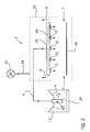
- FIG. 1 is a schematic representation of a preferred embodiment of the apparatus according to the present invention.
- FIG. 2 is a schematic representation of a preferred embodiment of the apparatus according to the present invention with a plurality of nozzles;
- FIG. 3 is a schematic representation of the exhaust system of a preferred embodiment of the apparatus according to the present.
- FIG. 1 illustrates an apparatus 2 for spraying particulate solids.
- feed line 4 has a first end 6 coupled to a pressurized-air line schematically shown at “D”.
- Line 4 (here with a line diameter of 6 mm) and therefore also the Venturi nozzle, has an air flow volume of 1.5 m 3 /h applied to it by means of the pressurized-air line D.
- the second end, the free opening 8 of line 4 is provided with a spraying nozzle 10 .
- Line 4 passes through reservoir 12 containing particulate corundum.
- the corundum has a specific weight of 4 g/cm 3 .
- a Venturi nozzle 14 is inserted in line 4 . Corundum is sucked out of reservoir 12 by the suction caused by Venturi nozzle 14 through a vacuum line 16 in operation, and in a swirled state into the feed line.
- the transportation airflow has a pressure of 6 bar.
- Reservoir 12 is open to the ambient. It is regularly refilled as the corundum is consumed.
- Line 4 is predominantly made of stainless steel. It does, however, also have a portion 4 a of flexible plastic material. At least in those areas in which plastic parts are being used, the apparatus is grounded to avoid an electrostatic charge.
- a flexible plastic line 4 a the free opening 8 with nozzle 10 set on it is allowed to be positioned at exactly the desired distance to the substrate to be coated.
- Corundum K has an average diameter of 60 ⁇ m. Corundum K is sprayed onto the surface of substrate 18 by nozzle 10 .
- Substrate 18 in the present case a high-density fiber board, is coated with a wet and adhesive, not yet cured layer 20 of melamine resin (layer thickness 50 ⁇ m).
- Spraying cone 11 of spraying nozzle 10 is indicated in FIG. 1 ; it extends over the entire width of high-density fiber board 18 .
- Substrate 18 is passed below spraying nozzle 10 at a speed of 60 m/min by conveyer means, which are indicated as a roller 22 .
- An overlay paper with a paper weight of 30 g/m 2 and a web width of 210 cm is filled with liquid melamine resin in an impregnation system with squeeze-roller dosage.
- the amount of melamine resin applied is about 120 g/m 2 .
- the solids content of the melamine resin is 50%.
- the impregnated overlay paper will be referred to as an impregnate in the following.
- 20 g/m 2 corundum powder (particle size 40 ⁇ m) is sprayed onto the impregnate using a spraying apparatus having 12 spraying nozzles over a web width of 210 cm onto the top side of the wet impregnate.
- the spraying apparatus corresponds to the apparatus illustrated in FIG. 1 .
- the web velocity of the impregnate below the 12 fixed spraying nozzles is about 80 m/min.
- the corundum powder is applied to the surface of the impregnate with a distribution accuracy of 0.5 g/m 2 .
- the corundum powder applied to the impregnate sinks into the melamine resin layer.
- the corundum powder is completely enveloped by the melamine resin.
- the thickness of the melamine resin/corundum layer is about 100 ⁇ m measured after drying. Envelopment of the corundum powder by the melamine resin as far as possible, or completely, if possible, is a precondition for the transparent coating desired.
- the corundum-containing overlay paper is dried to a residual moisture of 16 to 18 weight % with respect to dry matter content of the impregnate in an air flotation dryer. Subsequently, an additional melamine layer of 30 g/m 2 to 40 g/m 2 is applied to the underside of the impregnate with a screen applying mechanism. While passing through further drying zones of the air flotation dryer, a residual moisture of 6 weight % to 7 weight % of the impregnate is adjusted.
- the corundum-containing substrate is turned over and pressed onto a high-density fiber board in combination with melamine resin impregnated decorative paper.
- the resulting board can be used as a high-grade surface for laminate flooring in abrasion class AC4.
- a high-density fiber board (HDF) is decoratively patterned on its top side with a direct print in a 3-color printing process. Subsequently, a melamine resin layer of 60 g/m 2 is applied using a roller-applying mechanism. 15 g/m 2 corundum powder (particle size: 60 ⁇ m) is sprayed into the still liquid melamine resin with an apparatus schematically illustrated in FIG. 1 .
- the melamine coating with the embedded corundum powder is predried in a hot air dryer to such an extent that the surface coating has a residual moisture of about 15 weight % with respect to dry matter.
- a further protective layer of cellulose fibers and melamine resin is applied, and this surface structure is precondensed with hot air to such an extent that it is adhesive-free, but the melamine resin is not yet cross-linked.
- the printed and corundum-coated board is pressed in a short-cycle press (16 sec. at 160° C. on the board surface, 3 N/mm 2 ).
- a melamine film is applied to the underside of the high-density fiber board as a counteracting layer, which ensures that the underside of the board is protected and the board remains planar.
- the finished board is suitable as a panel for decorating walls, ceilings or floors.
- FIGS. 2 and 3 With reference to FIGS. 2 and 3 in the following a preferred embodiment of the apparatus according to the invention is explained.
- the same reference numerals design the same parts as in FIG. 1 .
- the reservoir 12 which contains the corundum K is equipped with a base 24 with air inlets. Via base 24 with air inlets air flows through the reservoir 12 from the lower area, thereby fluidizing the corundum.
- the unit comprising Venturi-nozzle 14 and vacuum intake line 16 which is described in detail in FIG. 1 , is shown here as injector 26 .
- the injector 26 supplies one or several lines 4 through which the swirled corundum is fed to the spraying nozzles 10 .
- the pressure in the feed lines is usually 0.2 to 4 bar, mostly 1 to 3.5 bar.
- the line or the lines 4 empty into a nozzle holder 28 , which accommodates a plurality of nozzles 10 which are distributed across the width of the substrate 18 .
- the nozzle holder 28 distributes the swirled corundum K via distribution lines 4 b , which are arranged in the nozzle holder 28 , to the spraying nozzles 10 .
- the nozzle holder 28 can be adjusted individually in its height over the substrate. Within the nozzle holder 28 the spraying nozzles 10 are individually adjustable around their axes.
- the nozzle holder 28 is encircled by a casing 30 which is indicated in FIG. 2 .
- An extraction system 32 is connected with the casing 30 .
- the extraction system 32 extracts via extraction line 34 the carrier air which is ejected from the spraying nozzles 10 .
- the airflow of the extracted air is indicated as A in FIG. 2 .
- the casing 30 is open towards the environment, preferably at the height of the substrate 18. Further, feed air F can be taken in to achieve a pressure equilibrium.
- FIG. 3 shows a preferred embodiment of the spray and extraction device.
- an inner casing 36 is mounted into the casing 30 .
- a cover 38 is inserted between the side of the nozzle holder 28 and the inner casing 36 .
- an exhaust channel 40 is created which channels the exhaust air A and—if required—feed air F.
- the exhaust 32 creates this air stream via exhaustion line 34 .
- the embodiment according to FIG. 3 prevents effectively deposits on the upper side of the nozzle holder 28 .
Landscapes
- Engineering & Computer Science (AREA)
- Architecture (AREA)
- Life Sciences & Earth Sciences (AREA)
- Wood Science & Technology (AREA)
- Civil Engineering (AREA)
- Structural Engineering (AREA)
- Application Of Or Painting With Fluid Materials (AREA)
Abstract
Description
- The invention relates to a method and a system for introducing particulate solids into a substrate.
- In the following, especially papers, in particular carrier papers or decorative papers, but also boards and panels of plastic material, wood or wood-based material, which are used on the ceiling, wall or floor, will be referred to as substrates.
- Applying particulate solids is interesting in particular, when thin layers of particulate solids are to be applied on a substrate. The particulate solids are relatively heavy and hard. They have a specific weight of more than 2 g/cm3, often more than 3 g/cm3. The Mohs-hardness amounts to 8-10. The typical case of application of the present invention is the application of corundum, silicates or other particulate solids on a substrate in order to improve its surface properties. When corundum is applied, for example, on synthetic resin layers and surface coatings thereof, their abrasion resistance is improved. The essential precondition is that the particulate solids do not form the surface of the substrate. They must be embedded in a layer near the surface to achieve improved abrasion resistance, for example. Silicates dispersed in synthetic resin layers improve, for example, the scratch resistance of surface coatings.
- Various technical approaches are known for the application of such particulate solids. A group of approaches aims at binding the particulate solids in liquids from the start, to then roll them on, cast them on or to spread them. In particular, WO 00/44984, DE 196 04 907 or DE 195 08 797 describe a dispersion containing particulate solids. This dispersion is applied by a flushing nozzle from below onto each substrate to be coated. Further it is suggested that additives be added to such dispersions to improve the handling of such particulate solids. The additives can be fibers and/or spherical bodies (glass spheres). It is disadvantageous that the manufacture and processing of the dispersion is very troublesome, as it has to be avoided, that the particulate solids settle. Even after short interruptions of production, the application apparatus must be fully cleaned, since the dispersion will otherwise block lines and nozzles. Moreover, the application amount varies strongly. As an alternative, WO 2005/042644 suggests sprinkling such particulate solids onto the substrate. Particulate solids are sprinkled on the substrate via a roller arrangement, below which the substrate is passed. This arrangement is simple in its mechanic setup and operation, but the uniformity and precision of the application is not satisfactory and mechanical wear is very high. Moreover, in a second step, fibers must be applied on the surface of the substrate in a very troublesome manner and selectively oriented in order to ensure the embedding of the particulate solids.
- All approaches must face the problem that the particulate solids, such as corundum, silicates or other particles are mostly extremely abrasive. The methods known from the state of the art therefore attempt to make the contact between the particulate solids and the corresponding conveying apparatus as delicate as possible to minimize the abrasion on the conveying apparatus. Embedding the particulate solids in synthetic resin, which is extremely troublesome in practice, effectively envelopes the particles. Sprinkling via a roller arrangement avoids interfering friction as far as possible.
- It is therefore an object of the present invention to provide an apparatus and a method with which particulate solids can be applied on a substrate in an economical manner and embedded in a layer near the surface.
- The approach according to the present invention provides an apparatus which is configured to spray particulate solids onto a substrate which is covered with a wet and/or adhesive synthetic resin layer, with the aid of a feed line, wherein, at its first end, means for generating a pressurized gas are arranged and, at its second end, it has a free opening which further has a reservoir for particulate solids and a nozzle for generating a pressure differential, wherein the reservoir and the nozzle are inserted in the feed line in such a way that in an operative state particulate solids are transferred and swirled from the reservoir into the feed line by the pressure differential generated by the nozzle, then transported to the free opening of the line from which the particulate solids are then ejected and sprayed into the wet and/or adhesive synthetic resin layer.
- Tests have shown that, in contrast to views previously held by experts, spraying of particulate solids onto a substrate, and therefore spraying the particles into the wet and/or adhesive synthetic resin layer, is quite easily possible. Wear and tear on the apparatus is surprisingly small, in particular, when the solids particles are sufficiently swirled. The apparatus according to the present invention needs hardly any moving parts for spraying the particulate solids which is very advantageous for the industrial application. By exclusively spraying the solids particles it is achieved that the particulate solids are spread with particular precision.
- The swirling, achieved among the solids particles as a result of the pressure differential is an essential precondition for uniform spraying of the particulate solids. A preferred embodiment of the apparatus according to the present invention provides that a Venturi nozzle is inserted in the feed line. It generates a vacuum in the line. The Venturi nozzle is inserted in the feed line of the apparatus according to the present invention in such a way that it sucks out the particulate solid out of the reservoir into the feed line by the vacuum it creates, and the particles are swirled and carried along by the gas flow where they remain a homogeneous gas-solid mixture, until they impact on the wet and/or adhesive synthetic resin layer of the substrate where the solids particles are deposited as an extremely uniform layer and sink into the synthetic resin layer. According to a further preferred embodiment of the apparatus according to the present invention, the particulate solids are fluidized in the reservoir in operation. Preferably they are passed through by air or another inert gas and are thus kept in movement in the reservoir.
- According to another preferred embodiment, the apparatus according to claim 1 is provided with at least one spraying nozzle at the open end. The spraying nozzle allows the coating of the substrate to be precisely controlled. The form of the spraying cone can be adjusted as desired, depending on the choice of nozzle, to achieve a predetermined spraying result on the substrate. The form of the spraying nozzle also depends, for example, on whether the opening of the feed line is stationary or mobile (which will be discussed below). A wide spectrum of nozzles or nozzle openings can be used for the apparatus according to the present invention, for example, nozzles with openings in the form of a circular annulus or nozzles with openings in the form of a slit. To coat wider substrates, such as wood-based panels, it is also possible to arrange a plurality of spraying nozzles side by side. A plurality of spraying nozzles can be in communication with the end of the feed line via a manifold, without the uniformity of the spraying process being negatively affected. A plurality of apparatuses according to the present invention can also be arranged in parallel, each equipped with one or more nozzles. According to a further preferred embodiment the nozzles can be adjusted with regard to their longitudinal or transverse axes.
- Depending on each case of application, the feed lines of the apparatus according to the present invention can be chosen. They can be rigid lines (tubes) or flexible lines (hoses). Hoses are advantageous in particular, when the opening of the second end or the spraying nozzle arranged there is configured to be mobile. Lines and spraying nozzles, but also the manifolds, can be made of plastic materials according to a preferred embodiment of the invention. The apparatus is thus comprised of lightweight components in a cost-effective manner. However, components of different materials can also be combined. The lines can have, for example, sections of metal and others of plastic. Ceramic components can also be used for the manufacture of the above-mentioned lines, spraying nozzles or manifolds.
- Preferably the apparatus according to the present invention also has means for conveying the substrate. The substrate, depending on whether it is decorative paper, veneer or another wood-based material surface, can be simply placed on the conveying means or fixed there. It is then passed under the stationary or mobile opening or spraying nozzle of the apparatus and coated with the particulate solid. If necessary, the substrate can be fixed on the means for conveying, whether by vacuum, or by other means such as e.g. opposed rollers or conveying bands. The provision of such means for conveying enables the substrate to be coated with solid particles economically and on an industrial scale.
- It is deemed a particular advantage of the present invention that the apparatus according to the present invention can also be used by itself. Preferably, however, the apparatus is incorporated in a system for surface coating. The application of synthetic resin or varnish on the wood-based material surfaces is usually carried out in impregnating plants or varnishing plants with operating speeds of about 30 m/min to about 100 m/min, often between 40 m/min and 60 m/min. With these operating speeds, the spraying apparatus according to the present invention can be easily integrated in these plants. The compact structure of the apparatus is of great advantage herefor. In integrated apparatuses, conveying means are often provided to transport the substrates to be processed or coated through all and sundry stations of the complex coating plants.
- According to the present invention, a wide range of particulate solids can be processed in the apparatus according to claim 1. Often corundum is used, but the use of silicates, carbides or diamond powder is also conceivable. The particulate solids used have a specific weight of often more than 2 g/cm3, often more than 3 g/cm3, usually with diameters of 30 to 100 μm, preferably with diameters of 40 μm to 60 μm. They are embedded in synthetic resin layers on the surface of carrier or decorative papers by being sprayed on or into them, but they are also embedded in synthetic resin layers directly on the surface of wood-based materials, to improve the quality of the surface coating, typically to enhance the abrasion resistance or scratch resistance. Preferably, when the particulate solids are sprayed on or into the wet and/or adhesive synthetic resin layer, it has a layer thickness which is at least half of the average diameter of the particulate solid, which means layer thicknesses of 15 μm to 50 μm. When the particles are sprayed into the synthetic resin they are largely enveloped by it due to a displacement effect. Alternatively a further synthetic resin layer can be applied after the spraying process to complete the embedding of the particulate solids.
- Almost any amount of solids particles can be applied to the substrate with the apparatus according to the present invention. It is surprising that tests have shown that small amounts of particulate solids can also be reliably and uniformly applied. Amounts of up to 100 g/m2, preferably of up to 80 g/m2, particularly preferably of up to 50 g/m2, advantageously of up to 30 g/m2, can be applied to the substrate with high precision by means of the apparatus according to the present invention and, as mentioned above, while maintaining a high working speed.
- It is deemed as particularly advantageous, that a high uniformity can be achieved in the application of solids particles with the apparatus according to the present invention, which is superior to the prior art methods. The uniformity of the particle application is important in more than one respect; on the one hand an increased application of solids negatively affects the transparency of the substrate surface. On the other hand substantial safety margins have to be provided in the application of solids particles to offset strong variations in uniformity, when predetermined application amounts have to be complied with. This negatively affects costs and leads to increased wear on the application apparatuses.
- According to the present invention, the solid particles can be sprinkled on the substrate with a precision of up to ±0.8 g/m2, preferably of up to ±0.5 g/m2. Particularly preferably, the application precision can be even more tightly defined, and is at up to ±0.3 g/m2 according to the present invention. Advantageously an application precision of up to ±0.1 g/m2 can be achieved. In prior art methods, the spreading precision achieved is above ±2 g/m2. In contrast, the approach according to the present invention affords substantial economic and technical advantages.
- The apparatus according to the present invention, according to an advantageous embodiment, affords various possibilities to individually adjust the application of the particulate solids. For instance, the free opening of the feed line, if necessary with the installed spraying nozzle, can be arranged moveable in parallel to the plane of the substrate to be coated, for example it can be traversable on a rail above the substrate to be coated. Alternatively or additionally, the distance to the surface can be varied. The movement of the free opening relative to the substrate is adapted to the feed velocity of the conveyer means which transports the substrate through the apparatus according to the present invention. Alternatively, the apparatus according to the present invention can also be adapted to the respective substrate by providing a corresponding number of spraying nozzles. Groups of nozzles can be connected, for example, to the end of the feed line via manifolds, to achieve a predetermined spreading pattern. The application of the particulate solids can therefore be individually adapted in a wide range to the substrate to be sprayed using the various possibilities of adjustment. Application methods known from the state of the art do not allow the application amount and the distribution of the particulate solids to be individually adjusted in this manner.
- The apparatus according to the present invention, in a preferred embodiment, provides that further means for modifying, in particular for coating the particulate solids are present in the feed line. The modifying process can be a coating process, for example, to provide for better bonding of the particulate solids on the substrate or to give the particulate solids improved optical properties. Often the solids particles are silanized, for example, to achieve better adhesion on the substrate. The means for modifying are inserted in the line between the reservoir and the end opening, and then the substance for modifying is sprayed into the line or, preferably, sucked into the line in the same way as the particulate solids by means of a pressure differential, and to envelop the particulate solids.
- The apparatus according to the present invention also allows varying amounts of particulate solids to be applied due to its high precision, i.e. a precise differentiation can be made between areas in which solids are applied to the substrate and areas in which less, more or no solids are applied to the substrate. This allows substrates to be produced having discrete sections with different amounts of particulate solids.
- The method according to the present invention provides that particulate solids are sprinkled into a wet and/or an adhesive synthetic resin layer of a substrate, comprising the steps of:
-
- coating the substrate with a wet and/or adhesive synthetic resin layer,
- building up gas pressure in a feed line,
- generating a pressure differential in the line,
- swirling and carrying along of particulate solids having a specific weight of more than 2 g/cm3 in the line,
- ejecting swirled particulate solids out of the line into the surface of the wet and/or adhesive synthetic resin layer of the substrate.
- According to the present invention it is provided that particulate solids are sprayed into a synthetic resin layer having a wet and/or adhesive surface of a substrate. Spraying particulate solids into such a wet and/or adhesive substrate coated with synthetic resin allows the substrate to be extremely uniformly coated. Typically the substrate can have not yet completely reacted synthetic resin applied to it, or it can be coated with paint or varnish. It can also be decorative paper, however, impregnated with not yet dried melamine resin. Embedding the sprayed-on particulate solids in the wet and/or adhesive surface of the substrate requires the use of much less of these wet and/or adhesive coating substances than prior art methods, for example those which apply the solids particles in the form of dispersions. Subsequent drying or curing of the wet and/or adhesive coating additionally contributes to the fixing of the particulate solids. It is essential that the particulate solids penetrate the synthetic resin layer as deeply as possible. They should not lie on the surface of the synthetic resin layer but should be embedded in the layer.
- It has proven advantageous to dry or cure the wet and/or adhesive synthetic resin layer after the insertion of the particulate solids. Usually this is done in a dryer or furnace, through which the coated substrate passes.
- The present invention attempts to insert the sprayed-on particulate solid as completely as possible within the synthetic resin layer. Solids particles which do not penetrate into the synthetic resin layer or do not adhere to the surface of the substrate can be recycled to the reservoir by means of a vacuum system and subsequent visual inspection. If the method according to the present invention is carried out in a way in which the particulate solids do not deeply penetrate the synthetic resin layer and are therefore not completely enclosed by the synthetic resin, it is advisable to subsequently apply at least one layer of a synthetic resin to enclose the exposed portions of the particulate solids.
- The method according to the present invention is implemented in the above described apparatus according to the present invention. It is simple and uncomplicated in its technical application, in particular it is insensitive with respect to standstill. The special requirement of the deep penetration of the particulate solids in the synthetic resin layer is excellently implemented. The relatively high specific weight of the particulate solids, in combination with the air flow causes sufficient penetration in the synthetic resin layer.
- The gas pressure is built up with simple means, for example, by means of a pump or coupling to a centrally supplied pressurized-air line. The change-over from the higher to the reduced pressure is suitably realized by means of a nozzle, preferably by means of a Venturi nozzle. The particles are sucked out of the reservoir due to the pressure drop in the feed line caused by the nozzle, for example in accordance with the functioning principle of a glass filter pump.
- According to another advantageous embodiment of the method according to the present invention, the spraying cone for spraying the solids onto the substrate is provided by a spraying nozzle set onto the free opening of the line. The spraying cone can be adapted to the individual requirement of each substrate as previously described in the description of the apparatus according to the invention by optimizing type and orientation of the spraying nozzle. Optimization of the spraying nozzle is carried out in practical tests.
- The spraying nozzle can be configured, for example, so that the substrate is intermittently sprayed. This causes sections of the substrate, such as in strips or transverse stripes, to be sprinkled with solid. For instance, sections of a wall, ceiling or floor panel are only sprinkled in places where a surface provided with particulate solids is indeed desired. In places where separating saws are used to produce individual panels after sprinkling the solids particles, coating with particulate solids can be omitted or at least substantially reduced, where it would interfere and cause wear on the saws.
- The above mentioned application amounts of up to 100 g/m2 and in particular the precision of coating of up to 0.8 g/m2, preferably of up to 0.1 g/m2 can also be achieved by adapting the gas throughput, the nozzle geometry, in particular of the spreading nozzle, and the speed of the substrate movement relative to the apparatus, but also by increasing or reducing the distance between the substrate and the spraying nozzle. Obtaining the optimum adjustment of these parameters in conformity with the corresponding application is within the usual overhead for optimizing such apparatuses.
- A substrate particularly uniformly coated with solids particles is also part of the subject matter of the present invention, wherein the particulate solids are inserted in a synthetic resin layer. Unlike previous substrates, decorative papers and panels can be provided, in particular, which are coated with particulate solids within stringent tolerances. The tolerance for the application amount of the particulate solids, according to a simple embodiment of the present invention, is up to ±0.8 g/m2, the tolerance according to a preferred embodiment is up to ±0.5 g/m2, particularly preferably up to ±0.3 g/m2, advantageously up to +0.1 g/m2. The uniform layer distribution allows abrasion values for the respective substrate, such as for achieving a particular abrasion resistance, to be achieved with a more sparing use of solids particles than has been previously possible.
- According to a preferred embodiment of the invention, the thus coated substrate is part of a multilayer surface coating. In particular, the synthetic resin layer according to the present invention, which is especially uniformly coated with corundum, is coated by a further synthetic resin layer.
- Essential details of the present invention will now be described with reference to an exemplary embodiment. In the figures:
-
FIG. 1 is a schematic representation of a preferred embodiment of the apparatus according to the present invention; -
FIG. 2 is a schematic representation of a preferred embodiment of the apparatus according to the present invention with a plurality of nozzles; -
FIG. 3 is a schematic representation of the exhaust system of a preferred embodiment of the apparatus according to the present. -
FIG. 1 illustrates anapparatus 2 for spraying particulate solids. Inapparatus 2, feedline 4 has afirst end 6 coupled to a pressurized-air line schematically shown at “D”. Line 4 (here with a line diameter of 6 mm) and therefore also the Venturi nozzle, has an air flow volume of 1.5 m3/h applied to it by means of the pressurized-air line D. The second end, thefree opening 8 ofline 4, is provided with a sprayingnozzle 10.Line 4 passes throughreservoir 12 containing particulate corundum. The corundum has a specific weight of 4 g/cm3. In the area ofreservoir 12 containing corundum, aVenturi nozzle 14 is inserted inline 4. Corundum is sucked out ofreservoir 12 by the suction caused byVenturi nozzle 14 through a vacuum line 16 in operation, and in a swirled state into the feed line. The transportation airflow has a pressure of 6 bar. -
Reservoir 12 is open to the ambient. It is regularly refilled as the corundum is consumed.Line 4 is predominantly made of stainless steel. It does, however, also have aportion 4 a of flexible plastic material. At least in those areas in which plastic parts are being used, the apparatus is grounded to avoid an electrostatic charge. By means of a flexibleplastic line 4 a thefree opening 8 withnozzle 10 set on it is allowed to be positioned at exactly the desired distance to the substrate to be coated. - Under the above indicated pressure conditions, an amount of 50 g/m2 corundum, schematically shown at “K” is taken out of
reservoir 12 and transferred to the gas flow, and is sprayed by sprayingnozzle 10. Corundum K has an average diameter of 60 μm. Corundum K is sprayed onto the surface ofsubstrate 18 bynozzle 10.Substrate 18, in the present case a high-density fiber board, is coated with a wet and adhesive, not yet curedlayer 20 of melamine resin (layer thickness 50 μm). - Spraying cone 11 of spraying
nozzle 10 is indicated inFIG. 1 ; it extends over the entire width of high-density fiber board 18.Substrate 18 is passed below sprayingnozzle 10 at a speed of 60 m/min by conveyer means, which are indicated as aroller 22. - 50 g/m2 corundum K with a distribution accuracy of 0.5 g/m2 are sprayed into
melamine resin layer 20. The corundum particles sink almost completely intomelamine resin layer 20. Subsequent to spraying of the corundum particles, the melamine resin layer is dried. Because corundum particles and melamine resin show almost identical indices of refraction, a transparent layer is created. - Further exemplary embodiments explain the advantages of the present invention:
- An overlay paper with a paper weight of 30 g/m2 and a web width of 210 cm is filled with liquid melamine resin in an impregnation system with squeeze-roller dosage. The amount of melamine resin applied is about 120 g/m2. The solids content of the melamine resin is 50%. The impregnated overlay paper will be referred to as an impregnate in the following. 20 g/m2 corundum powder (
particle size 40 μm) is sprayed onto the impregnate using a spraying apparatus having 12 spraying nozzles over a web width of 210 cm onto the top side of the wet impregnate. The spraying apparatus corresponds to the apparatus illustrated inFIG. 1 . The web velocity of the impregnate below the 12 fixed spraying nozzles is about 80 m/min. - The corundum powder is applied to the surface of the impregnate with a distribution accuracy of 0.5 g/m2. The corundum powder applied to the impregnate sinks into the melamine resin layer. The corundum powder is completely enveloped by the melamine resin. The thickness of the melamine resin/corundum layer is about 100 μm measured after drying. Envelopment of the corundum powder by the melamine resin as far as possible, or completely, if possible, is a precondition for the transparent coating desired.
- The corundum-containing overlay paper is dried to a residual moisture of 16 to 18 weight % with respect to dry matter content of the impregnate in an air flotation dryer. Subsequently, an additional melamine layer of 30 g/m2 to 40 g/m2 is applied to the underside of the impregnate with a screen applying mechanism. While passing through further drying zones of the air flotation dryer, a residual moisture of 6 weight % to 7 weight % of the impregnate is adjusted.
- The corundum-containing substrate is turned over and pressed onto a high-density fiber board in combination with melamine resin impregnated decorative paper. The resulting board can be used as a high-grade surface for laminate flooring in abrasion class AC4.
- A high-density fiber board (HDF) is decoratively patterned on its top side with a direct print in a 3-color printing process. Subsequently, a melamine resin layer of 60 g/m2 is applied using a roller-applying mechanism. 15 g/m2 corundum powder (particle size: 60 μm) is sprayed into the still liquid melamine resin with an apparatus schematically illustrated in
FIG. 1 . - The melamine coating with the embedded corundum powder is predried in a hot air dryer to such an extent that the surface coating has a residual moisture of about 15 weight % with respect to dry matter. Next, a further protective layer of cellulose fibers and melamine resin is applied, and this surface structure is precondensed with hot air to such an extent that it is adhesive-free, but the melamine resin is not yet cross-linked.
- The printed and corundum-coated board is pressed in a short-cycle press (16 sec. at 160° C. on the board surface, 3 N/mm2). Herein, a melamine film is applied to the underside of the high-density fiber board as a counteracting layer, which ensures that the underside of the board is protected and the board remains planar. The finished board is suitable as a panel for decorating walls, ceilings or floors.
- With reference to
FIGS. 2 and 3 in the following a preferred embodiment of the apparatus according to the invention is explained. In theFIGS. 2 and 3 , the same reference numerals design the same parts as inFIG. 1 . - The
reservoir 12 which contains the corundum K is equipped with a base 24 with air inlets. Viabase 24 with air inlets air flows through thereservoir 12 from the lower area, thereby fluidizing the corundum. The unit comprising Venturi-nozzle 14 and vacuum intake line 16, which is described in detail inFIG. 1 , is shown here as injector 26. The injector 26 supplies one orseveral lines 4 through which the swirled corundum is fed to the sprayingnozzles 10. The pressure in the feed lines is usually 0.2 to 4 bar, mostly 1 to 3.5 bar. - The line or the
lines 4 empty into anozzle holder 28, which accommodates a plurality ofnozzles 10 which are distributed across the width of thesubstrate 18. Thenozzle holder 28 distributes the swirled corundum K viadistribution lines 4 b, which are arranged in thenozzle holder 28, to the sprayingnozzles 10. Thenozzle holder 28 can be adjusted individually in its height over the substrate. Within thenozzle holder 28 the sprayingnozzles 10 are individually adjustable around their axes. - The
nozzle holder 28 is encircled by acasing 30 which is indicated inFIG. 2 . Anextraction system 32 is connected with thecasing 30. Theextraction system 32 extracts viaextraction line 34 the carrier air which is ejected from the sprayingnozzles 10. The airflow of the extracted air is indicated as A inFIG. 2 . Thus, undesired swirls on the substrate are avoided. In order to avoid a vacuum, thecasing 30 is open towards the environment, preferably at the height of thesubstrate 18. Further, feed air F can be taken in to achieve a pressure equilibrium. -
FIG. 3 shows a preferred embodiment of the spray and extraction device. In order to avoid deposits on the upper side of thenozzle holder 28, aninner casing 36 is mounted into thecasing 30. Further, acover 38 is inserted between the side of thenozzle holder 28 and theinner casing 36. Thus, anexhaust channel 40 is created which channels the exhaust air A and—if required—feed air F. Theexhaust 32 creates this air stream viaexhaustion line 34. The embodiment according toFIG. 3 prevents effectively deposits on the upper side of thenozzle holder 28.
Claims (22)
Priority Applications (2)
| Application Number | Priority Date | Filing Date | Title |
|---|---|---|---|
| US13/346,846 US8586137B2 (en) | 2005-12-16 | 2012-01-10 | Method and system for applying particulate solids on a substrate |
| US14/055,919 US9023475B2 (en) | 2005-12-16 | 2013-10-17 | Method and system for applying particulate solids on a substrate |
Applications Claiming Priority (3)
| Application Number | Priority Date | Filing Date | Title |
|---|---|---|---|
| DE102005060754.3 | 2005-12-16 | ||
| DE200510060754 DE102005060754A1 (en) | 2005-12-16 | 2005-12-16 | Method and installation for applying solid particles to a substrate |
| DE102005060754 | 2005-12-16 |
Related Child Applications (1)
| Application Number | Title | Priority Date | Filing Date |
|---|---|---|---|
| US13/346,846 Division US8586137B2 (en) | 2005-12-16 | 2012-01-10 | Method and system for applying particulate solids on a substrate |
Publications (2)
| Publication Number | Publication Date |
|---|---|
| US20070151663A1 true US20070151663A1 (en) | 2007-07-05 |
| US8096261B2 US8096261B2 (en) | 2012-01-17 |
Family
ID=38008276
Family Applications (3)
| Application Number | Title | Priority Date | Filing Date |
|---|---|---|---|
| US11/640,059 Expired - Fee Related US8096261B2 (en) | 2005-12-16 | 2006-12-15 | Method and system for applying particulate solids on a substrate |
| US13/346,846 Expired - Fee Related US8586137B2 (en) | 2005-12-16 | 2012-01-10 | Method and system for applying particulate solids on a substrate |
| US14/055,919 Active US9023475B2 (en) | 2005-12-16 | 2013-10-17 | Method and system for applying particulate solids on a substrate |
Family Applications After (2)
| Application Number | Title | Priority Date | Filing Date |
|---|---|---|---|
| US13/346,846 Expired - Fee Related US8586137B2 (en) | 2005-12-16 | 2012-01-10 | Method and system for applying particulate solids on a substrate |
| US14/055,919 Active US9023475B2 (en) | 2005-12-16 | 2013-10-17 | Method and system for applying particulate solids on a substrate |
Country Status (5)
| Country | Link |
|---|---|
| US (3) | US8096261B2 (en) |
| EP (1) | EP1801290B1 (en) |
| DE (1) | DE102005060754A1 (en) |
| PL (1) | PL1801290T3 (en) |
| RU (1) | RU2374006C2 (en) |
Cited By (6)
| Publication number | Priority date | Publication date | Assignee | Title |
|---|---|---|---|---|
| US20110197923A1 (en) * | 2009-08-21 | 2011-08-18 | Battaglioli John L | Staged compressor water wash system |
| US20120052198A1 (en) * | 2010-08-24 | 2012-03-01 | Stecker William M | Methods of Applying Metal Coatings to Objects |
| EP2868802A1 (en) * | 2013-10-31 | 2015-05-06 | Valmet Technologies, Inc. | Arrangement of a fiber web production line and method of a fiber web production line |
| US10226960B2 (en) * | 2010-06-30 | 2019-03-12 | Flooring Technologies Ltd. | Apparatus for the refinement of a panel |
| US11179870B1 (en) * | 2015-05-18 | 2021-11-23 | Trusscore Inc. | Apparatus, methods, and systems for mixing and dispersing a dispersed phase in a medium |
| US20220136100A1 (en) * | 2020-10-30 | 2022-05-05 | Semes Co., Ltd. | Surface treatment apparatus and surface treatment method |
Families Citing this family (14)
| Publication number | Priority date | Publication date | Assignee | Title |
|---|---|---|---|---|
| DE102005060754A1 (en) * | 2005-12-16 | 2007-07-05 | Kronotec Ag | Method and installation for applying solid particles to a substrate |
| DE102007062407B4 (en) * | 2007-12-20 | 2010-05-12 | Resopal Gmbh | Multilayer composite panel |
| EP2106903A1 (en) | 2008-02-22 | 2009-10-07 | Hermes Schleifkörper GmbH | Method for scattering friction-inhibiting materials and accompanying device |
| DE102008012221B4 (en) * | 2008-03-03 | 2011-06-01 | Kronotec Ag | Method of painting a still wet sheet substrate |
| DE102009014638A1 (en) * | 2009-03-24 | 2010-09-30 | Clariant International Ltd. | Laminates containing hard, plate-shaped minerals |
| AT511413B1 (en) * | 2011-05-10 | 2015-02-15 | Steindl Roman Dipl Ing | METHOD FOR PRODUCING PAPER PRODUCTS |
| EP2935643B1 (en) * | 2012-12-21 | 2018-08-01 | Doosan Fuel Cell America, Inc. | Deposition cloud tower with adjustable field |
| CN105234051A (en) * | 2014-07-07 | 2016-01-13 | 上海图博可特石油管道涂层有限公司 | Anti-H2S and anti-CO2 drill pipe powder internal coating process for petroleum exploitation |
| GB2545026A (en) | 2015-12-04 | 2017-06-07 | Jean Boulle Luxury Paint Ltd | Reflective coating |
| PL3246175T3 (en) | 2016-05-20 | 2019-03-29 | Flooring Technologies Ltd | Method of producing an abrasion resistant wooden panel and production line for same |
| DE102017119400A1 (en) * | 2017-08-24 | 2019-02-28 | Flooring Technologies Ltd. | Process for coating a plate or web-shaped material and device for carrying out the process |
| EP3480030B1 (en) * | 2017-11-06 | 2020-05-13 | Flooring Technologies Ltd. | Method of producing an abrasion resistant wood-based panel and production line for same |
| ES2870156T3 (en) | 2019-01-22 | 2021-10-26 | Flooring Technologies Ltd | Procedure for the manufacture of a board of material derived from wood resistant to abrasion |
| PT3686029T (en) | 2019-01-23 | 2022-06-15 | Flooring Technologies Ltd | Method for producing an abrasion-resistant and waterproof multilayer panel and a panel obtained with said method |
Citations (2)
| Publication number | Priority date | Publication date | Assignee | Title |
|---|---|---|---|---|
| US3665918A (en) * | 1970-01-12 | 1972-05-30 | Johnson & Johnson | Conformable adhesive sheet |
| US6544336B1 (en) * | 2000-05-30 | 2003-04-08 | Creo Inc. | Apparatus for a high efficiency spray system |
Family Cites Families (17)
| Publication number | Priority date | Publication date | Assignee | Title |
|---|---|---|---|---|
| US2557266A (en) * | 1944-05-20 | 1951-06-19 | Du Pont | Reaction product of an acrylic acid resin and a resin containing hydroxyl groups |
| GB1333091A (en) * | 1970-11-12 | 1973-10-10 | Volstatic Coatings Ltd | Apparatus for spraying powder |
| US3974302A (en) * | 1974-11-26 | 1976-08-10 | Westinghouse Electric Corporation | Method of making patterned dry resin coated sheet insulation |
| SU1687026A3 (en) * | 1986-06-03 | 1991-10-23 | Сэн - Гобэн Витраж (Фирма) | Mixing device for producing gas-powder suspension flow |
| DE4037650A1 (en) * | 1990-11-27 | 1992-06-04 | Hoerter Gmbh | Coating ceramic object - by resin coating, heating and applying particles esp. of mineral or glass |
| US5279854A (en) * | 1992-01-27 | 1994-01-18 | Paragon Trade Brands, Inc. | Method and apparatus for zoned application of particles in fibrous material |
| ES2050598B1 (en) | 1992-02-27 | 1994-12-01 | Formica Espanola | IMPROVED PROCEDURE FOR MANUFACTURING EXTERIOR SHEETS WITH HIGH ABRASION RESISTANCE. |
| EP0609808B1 (en) * | 1993-02-02 | 1998-04-22 | TOKAI PULP Co., Ltd. | Thermo-adhesive, water-soluble or water-decomposable paper and method of manufacturing the same |
| DE4344552A1 (en) * | 1993-12-24 | 1995-06-29 | Giesecke & Devrient Gmbh | Method and device for equipping securities with authenticity features |
| DE19508797C1 (en) | 1995-03-15 | 1996-08-29 | Graudenz & Partner Consultatio | Process for making decorative paper for use in making abrasion resistant laminates |
| FR2743580B1 (en) | 1996-01-11 | 1998-04-03 | Mead Corp | METHOD FOR MANUFACTURING COATINGS WITH HIGH ABRASION RESISTANCE |
| US5681361A (en) * | 1996-01-11 | 1997-10-28 | Minnesota Mining And Manufacturing Company | Method of making an abrasive article and abrasive article produced thereby |
| ATE254692T1 (en) | 1999-01-26 | 2003-12-15 | Kronospan Tech Co Ltd | METHOD FOR IMPREGNATION OF DECORATIVE PAPERS |
| US20030017272A1 (en) * | 2001-07-20 | 2003-01-23 | Stevenson Michael J. | Bonding of granular materials to polyolefin surfaces |
| KR100877385B1 (en) * | 2001-11-13 | 2009-01-07 | 도요 고무 고교 가부시키가이샤 | Polishing pads and manufacturing method thereof |
| AU2003280363A1 (en) | 2003-09-30 | 2005-05-19 | Kronospan Technical Company Limited | Decorative paper with sprinkled corundum, coated with an adhesive |
| DE102005060754A1 (en) * | 2005-12-16 | 2007-07-05 | Kronotec Ag | Method and installation for applying solid particles to a substrate |
-
2005
- 2005-12-16 DE DE200510060754 patent/DE102005060754A1/en not_active Ceased
-
2006
- 2006-12-12 PL PL06025677T patent/PL1801290T3/en unknown
- 2006-12-12 EP EP06025677.3A patent/EP1801290B1/en not_active Not-in-force
- 2006-12-15 US US11/640,059 patent/US8096261B2/en not_active Expired - Fee Related
- 2006-12-15 RU RU2006144786A patent/RU2374006C2/en not_active IP Right Cessation
-
2012
- 2012-01-10 US US13/346,846 patent/US8586137B2/en not_active Expired - Fee Related
-
2013
- 2013-10-17 US US14/055,919 patent/US9023475B2/en active Active
Patent Citations (2)
| Publication number | Priority date | Publication date | Assignee | Title |
|---|---|---|---|---|
| US3665918A (en) * | 1970-01-12 | 1972-05-30 | Johnson & Johnson | Conformable adhesive sheet |
| US6544336B1 (en) * | 2000-05-30 | 2003-04-08 | Creo Inc. | Apparatus for a high efficiency spray system |
Cited By (10)
| Publication number | Priority date | Publication date | Assignee | Title |
|---|---|---|---|---|
| US20110197923A1 (en) * | 2009-08-21 | 2011-08-18 | Battaglioli John L | Staged compressor water wash system |
| US9016293B2 (en) * | 2009-08-21 | 2015-04-28 | Gas Turbine Efficiency Sweden Ab | Staged compressor water wash system |
| US10226960B2 (en) * | 2010-06-30 | 2019-03-12 | Flooring Technologies Ltd. | Apparatus for the refinement of a panel |
| US11472224B2 (en) | 2010-06-30 | 2022-10-18 | Flooring Technologies Ltd. | Apparatus for the refinement of a panel |
| US20120052198A1 (en) * | 2010-08-24 | 2012-03-01 | Stecker William M | Methods of Applying Metal Coatings to Objects |
| US8399052B2 (en) * | 2010-08-24 | 2013-03-19 | Alchemy Dimensional Graphics, Llc | Methods of applying metal coatings to objects |
| EP2868802A1 (en) * | 2013-10-31 | 2015-05-06 | Valmet Technologies, Inc. | Arrangement of a fiber web production line and method of a fiber web production line |
| US11179870B1 (en) * | 2015-05-18 | 2021-11-23 | Trusscore Inc. | Apparatus, methods, and systems for mixing and dispersing a dispersed phase in a medium |
| US20220136100A1 (en) * | 2020-10-30 | 2022-05-05 | Semes Co., Ltd. | Surface treatment apparatus and surface treatment method |
| US11866819B2 (en) * | 2020-10-30 | 2024-01-09 | Semes Co., Ltd. | Surface treatment apparatus and surface treatment method |
Also Published As
| Publication number | Publication date |
|---|---|
| PL1801290T3 (en) | 2020-07-13 |
| DE102005060754A1 (en) | 2007-07-05 |
| RU2006144786A (en) | 2008-06-20 |
| RU2374006C2 (en) | 2009-11-27 |
| US8586137B2 (en) | 2013-11-19 |
| US20120107497A1 (en) | 2012-05-03 |
| US9023475B2 (en) | 2015-05-05 |
| US8096261B2 (en) | 2012-01-17 |
| EP1801290A2 (en) | 2007-06-27 |
| EP1801290B1 (en) | 2019-11-20 |
| EP1801290A3 (en) | 2008-07-02 |
| US20140044958A1 (en) | 2014-02-13 |
Similar Documents
| Publication | Publication Date | Title |
|---|---|---|
| US9023475B2 (en) | Method and system for applying particulate solids on a substrate | |
| US10392812B2 (en) | Single layer scattering of powder surfaces | |
| CN101495243B (en) | Coating device comprising a flowing coating material | |
| RU2626948C2 (en) | Single layer pouring of powder surfaces | |
| SE520381C2 (en) | Procedure for making decorative panels | |
| CN113815343A (en) | Production line for carrying out the method for the manufacture of wear-resistant composite wood panels | |
| AU2010241049B2 (en) | Process and apparatus for manufacturing decorative papers and/or panels for flooring or surfacing of furniture, walls, etc. | |
| US12083769B2 (en) | Method for producing a matt support material provided with an anti-fingerprint coating | |
| US9782797B2 (en) | Method and device for producing a structured varnish surface | |
| US20220080769A1 (en) | Method for Producing an Abrasion-Resistant Wood Composite Board, and Production Line Therefor | |
| JP7033696B2 (en) | How to make a wear-resistant wood board | |
| US20170113248A1 (en) | Method for printing directly onto boards of wood-based material | |
| RU2792211C1 (en) | Method for obtaining matted base material with an anti-fingerprint coating | |
| RU2773231C2 (en) | Method for manufacturing a wear-resistant plate based on a wood material and production line for implementation thereof | |
| HK1035219A1 (en) | Method for impregnating decorative papers | |
| HK1035219B (en) | Method for impregnating decorative papers |
Legal Events
| Date | Code | Title | Description |
|---|---|---|---|
| AS | Assignment |
Owner name: KRONOTEC AG, SWITZERLAND Free format text: ASSIGNMENT OF ASSIGNORS INTEREST;ASSIGNORS:STEINMANN, PIUS;HUBNER, CHRISTIAN;REEL/FRAME:019022/0884 Effective date: 20070103 |
|
| AS | Assignment |
Owner name: KRONOTEC AG, SWITZERLAND Free format text: ASSIGNMENT OF ASSIGNORS INTEREST;ASSIGNORS:STEINMANN, PIUS;HUBNER, CHRISTIAN;BAUER, ERICH;REEL/FRAME:020344/0875;SIGNING DATES FROM 20071127 TO 20071205 Owner name: KRONOTEC AG, SWITZERLAND Free format text: ASSIGNMENT OF ASSIGNORS INTEREST;ASSIGNORS:STEINMANN, PIUS;HUBNER, CHRISTIAN;BAUER, ERICH;SIGNING DATES FROM 20071127 TO 20071205;REEL/FRAME:020344/0875 |
|
| ZAAA | Notice of allowance and fees due |
Free format text: ORIGINAL CODE: NOA |
|
| ZAAB | Notice of allowance mailed |
Free format text: ORIGINAL CODE: MN/=. |
|
| STCF | Information on status: patent grant |
Free format text: PATENTED CASE |
|
| FEPP | Fee payment procedure |
Free format text: PAYOR NUMBER ASSIGNED (ORIGINAL EVENT CODE: ASPN); ENTITY STATUS OF PATENT OWNER: LARGE ENTITY |
|
| FPAY | Fee payment |
Year of fee payment: 4 |
|
| AS | Assignment |
Owner name: SWISS KRONO TEC AG, SWITZERLAND Free format text: CHANGE OF NAME;ASSIGNOR:KRONOTEC AG;REEL/FRAME:041665/0359 Effective date: 20160301 |
|
| AS | Assignment |
Owner name: SWISS KRONO TEC AG, SWITZERLAND Free format text: CORRECTIVE ASSIGNMENT TO CORRECT THE DOCUMENT DATE PREVIOUSLY RECORDED AT REEL: 041665 FRAME: 0359. ASSIGNOR(S) HEREBY CONFIRMS THE CHANGE OF NAME;ASSIGNOR:KRONOTEC AG;REEL/FRAME:042084/0703 Effective date: 20170301 |
|
| MAFP | Maintenance fee payment |
Free format text: PAYMENT OF MAINTENANCE FEE, 8TH YEAR, LARGE ENTITY (ORIGINAL EVENT CODE: M1552); ENTITY STATUS OF PATENT OWNER: LARGE ENTITY Year of fee payment: 8 |
|
| FEPP | Fee payment procedure |
Free format text: MAINTENANCE FEE REMINDER MAILED (ORIGINAL EVENT CODE: REM.); ENTITY STATUS OF PATENT OWNER: LARGE ENTITY |
|
| LAPS | Lapse for failure to pay maintenance fees |
Free format text: PATENT EXPIRED FOR FAILURE TO PAY MAINTENANCE FEES (ORIGINAL EVENT CODE: EXP.); ENTITY STATUS OF PATENT OWNER: LARGE ENTITY |
|
| STCH | Information on status: patent discontinuation |
Free format text: PATENT EXPIRED DUE TO NONPAYMENT OF MAINTENANCE FEES UNDER 37 CFR 1.362 |
|
| FP | Lapsed due to failure to pay maintenance fee |
Effective date: 20240117 |