EP1801066A2 - Vorrichtung zum Zuführen von Verschlüssen - Google Patents
Vorrichtung zum Zuführen von Verschlüssen Download PDFInfo
- Publication number
- EP1801066A2 EP1801066A2 EP06115951A EP06115951A EP1801066A2 EP 1801066 A2 EP1801066 A2 EP 1801066A2 EP 06115951 A EP06115951 A EP 06115951A EP 06115951 A EP06115951 A EP 06115951A EP 1801066 A2 EP1801066 A2 EP 1801066A2
- Authority
- EP
- European Patent Office
- Prior art keywords
- caps
- channel
- drum
- entrance
- pipes
- Prior art date
- Legal status (The legal status is an assumption and is not a legal conclusion. Google has not performed a legal analysis and makes no representation as to the accuracy of the status listed.)
- Granted
Links
Images


Classifications
-
- B—PERFORMING OPERATIONS; TRANSPORTING
- B67—OPENING, CLOSING OR CLEANING BOTTLES, JARS OR SIMILAR CONTAINERS; LIQUID HANDLING
- B67B—APPLYING CLOSURE MEMBERS TO BOTTLES JARS, OR SIMILAR CONTAINERS; OPENING CLOSED CONTAINERS
- B67B3/00—Closing bottles, jars or similar containers by applying caps
- B67B3/02—Closing bottles, jars or similar containers by applying caps by applying flanged caps, e.g. crown caps, and securing by deformation of flanges
- B67B3/06—Feeding caps to capping heads
- B67B3/062—Feeding caps to capping heads from a magazine
-
- B—PERFORMING OPERATIONS; TRANSPORTING
- B65—CONVEYING; PACKING; STORING; HANDLING THIN OR FILAMENTARY MATERIAL
- B65G—TRANSPORT OR STORAGE DEVICES, e.g. CONVEYORS FOR LOADING OR TIPPING, SHOP CONVEYOR SYSTEMS OR PNEUMATIC TUBE CONVEYORS
- B65G47/00—Article or material-handling devices associated with conveyors; Methods employing such devices
- B65G47/34—Devices for discharging articles or materials from conveyor
- B65G47/46—Devices for discharging articles or materials from conveyor and distributing, e.g. automatically, to desired points
- B65G47/51—Devices for discharging articles or materials from conveyor and distributing, e.g. automatically, to desired points according to unprogrammed signals, e.g. influenced by supply situation at destination
- B65G47/5104—Devices for discharging articles or materials from conveyor and distributing, e.g. automatically, to desired points according to unprogrammed signals, e.g. influenced by supply situation at destination for articles
-
- B—PERFORMING OPERATIONS; TRANSPORTING
- B67—OPENING, CLOSING OR CLEANING BOTTLES, JARS OR SIMILAR CONTAINERS; LIQUID HANDLING
- B67B—APPLYING CLOSURE MEMBERS TO BOTTLES JARS, OR SIMILAR CONTAINERS; OPENING CLOSED CONTAINERS
- B67B3/00—Closing bottles, jars or similar containers by applying caps
- B67B3/003—Pretreatment of caps, e.g. cleaning, steaming, heating or sterilizing
-
- B—PERFORMING OPERATIONS; TRANSPORTING
- B65—CONVEYING; PACKING; STORING; HANDLING THIN OR FILAMENTARY MATERIAL
- B65G—TRANSPORT OR STORAGE DEVICES, e.g. CONVEYORS FOR LOADING OR TIPPING, SHOP CONVEYOR SYSTEMS OR PNEUMATIC TUBE CONVEYORS
- B65G47/00—Article or material-handling devices associated with conveyors; Methods employing such devices
- B65G47/34—Devices for discharging articles or materials from conveyor
- B65G47/46—Devices for discharging articles or materials from conveyor and distributing, e.g. automatically, to desired points
- B65G47/51—Devices for discharging articles or materials from conveyor and distributing, e.g. automatically, to desired points according to unprogrammed signals, e.g. influenced by supply situation at destination
- B65G47/5104—Devices for discharging articles or materials from conveyor and distributing, e.g. automatically, to desired points according to unprogrammed signals, e.g. influenced by supply situation at destination for articles
- B65G47/5109—Devices for discharging articles or materials from conveyor and distributing, e.g. automatically, to desired points according to unprogrammed signals, e.g. influenced by supply situation at destination for articles first In - First Out systems: FIFO
- B65G47/514—Devices for discharging articles or materials from conveyor and distributing, e.g. automatically, to desired points according to unprogrammed signals, e.g. influenced by supply situation at destination for articles first In - First Out systems: FIFO using stacking and/or destacking arrangements or stacks of articles or article carriers
-
- B—PERFORMING OPERATIONS; TRANSPORTING
- B65—CONVEYING; PACKING; STORING; HANDLING THIN OR FILAMENTARY MATERIAL
- B65G—TRANSPORT OR STORAGE DEVICES, e.g. CONVEYORS FOR LOADING OR TIPPING, SHOP CONVEYOR SYSTEMS OR PNEUMATIC TUBE CONVEYORS
- B65G47/00—Article or material-handling devices associated with conveyors; Methods employing such devices
- B65G47/74—Feeding, transfer, or discharging devices of particular kinds or types
- B65G47/88—Separating or stopping elements, e.g. fingers
- B65G47/8807—Separating or stopping elements, e.g. fingers with one stop
- B65G47/883—Fixed stop
- B65G47/8846—Fixed stop with a pivoting pusher element which lifts or releases the article
Definitions
- the present invention relates to a system for feeding bottle-tops to a bottle closing machine, in particular for feeding caps to a capping machine, comprising an accumulation device located on a cap feeding pathway.
- the present invention was developed in particular in view of its application to automatic plants for forming plastic bottles, filling and capping the bottles using plastic caps.
- an accumulation device for the caps is normally provided for on the cap feeding pathway.
- the accumulation device has a minimum capacity such as to ensure that all containers present in the bottle forming, filling and capping stations can be capped even should the supply of caps be temporarily interrupted.
- the document EP-B1-0993417 describes a plant for filling and capping bottles provided with a mobile buffer stock device for the caps capable of moving the caps at a predetermined rate along a feeding pathway.
- the mobile buffer stock device described in that document comprises an inner drum that rotates around a vertical axis provided around its periphery with a plurality of housings that engage respective caps and an external helicoidal runway along which the caps are made to advance at a predetermined rate.
- the caps advance in a continuous fashion along the feeding route at a rate and an instantaneous velocity that depends on the work rhythm of the capping machine, so that the accumulation device must be designed and produced for a specific capping machine and cannot be used with capping machines having different characteristics.
- the caps must fill each housing of the accumulation device since any discontinuities would cause operating problems, such as for example the failure to close all containers.
- a further drawback of the known solution consists in the fact that each cap must cover the entire helicoidal or spiral pathway of the accumulation device, which entails a high risk that the accumulation device produces dust due to abrasion of the caps, and causes unnecessary stress on the caps.
- the present invention aims to provide an accumulation device for a capping machine that enables the drawbacks of the known technique to be overcome.
- this goal is achieved by a cap feeding system having the characteristics subject of claim 1.
- an automatic plant for closing bottles 12 with plastic screw caps is indicated as 10.
- the plant 10 comprises a capping machine 14 having a turntable structure with a plurality of capping heads 16.
- the structure and operation of the machine 14 are known and thus their description lies outside the scope of the present invention.
- the plant 10 comprises a cap feeding system 18 that feeds a continuous flow of caps to the capping machine 14.
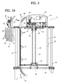
- the cap feeding system 18 comprises an accumulation device 20 lying along a cap feeding pathway that comprises an entrance channel 22 and an exit channel 24, both stationary.
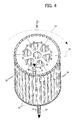
- the accumulation device 20 comprises a stationary structure 26 bearing a drum 28 rotating around a vertical axis 30.
- the drum 28 comprises a central shaft 32 that is supported such that it can rotate around an axis 30 on a stationary support 36 by means of bearings 34.
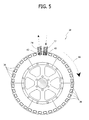
- the drum 28 comprises a plurality of peripheral pipes 38 equidistant one from the next in the circumferential direction and fixed with respect to the central shaft 32.
- Each pipe 38 has an upper extremity and a lower extremity, respectively for the entrance and exit of caps 40.
- Each pipe 38 forms a channel oriented vertically capable of receiving a pile of caps 40 (figure 3) disposed in contact one with the next.
- the plate 42 has an opening that communicates with the upper extremity of the exit channel 24.
- the drum 38 may be rotated stepwise so as to bring the pipes 38 successively into correspondence with the exit channel 24.
- the caps 40 slide down due to gravity into the top of channel 24 that runs from there downwards.
- a cap take-up device 44 of known structure and operation, is positioned to take up the caps 40 as they leave the lower end of the channel 24.
- a drive mechanism to control rotation of the drum 28 around the vertical axis 30 is indicated with 46.
- the drive mechanism 46 optional, comprises a stationary supporting plate 48 bearing a motor reducer unit 50 that causes the shaft 32 to rotate through two pulleys 52 connected by a toothed belt. This transmission may be direct or alternatively may be achieved through a pair of gears.
- the drive mechanism 46 comprises an encoder 54 that detects the angular position of the drum 28. In the example illustrated, the encoder 54 is connected to the shaft 32 by means of two gears 56.
- the entrance channel 22 is positioned such as to feed the caps 40 to the pipe 38 that at a given moment is positioned in correspondence to the entrance channel 22.
- the caps 40 move due to gravity down the entrance channel 22.
- an air jet may be provided that facilitates the movement of the caps 40 down the entrance channel 22.
- the entrance channel 22 terminates on a plate 58 which is part of the stationary supporting structure 26.
- the plate 58 bears the drive mechanism 46 and the support 36 upon which the upper extremity of the shaft 32 is mounted such that it can rotate
- the lower extremity of the entrance channel 22 faces onto the upper extremity of one of the various pipes 38.
- a holding device 60 is situated in the vicinity of the lower extremity of the entrance channel 22.
- the holding device 60 comprises a wheel 62 with star-shaped profile that is free to rotate around a horizontal axis and is positioned such that the caps 40 moving down the entrance channel 22 cause the wheel 62 to rotate by effect of their interaction with the star-shaped profile of the wheel 62.
- the wheel 62 is associated with a locking element 64, comprising for example a pneumatic actuator, capable of selectively blocking the wheel 62. When the locking element 64 is activated, movement of the caps 40 down the entrance channel 22 upstream of the holding device 60 is interrupted.
- This holding device may alternatively be constructed with a component that makes a linear movement or a rotation through levers, with mechanical, pneumatic or magnetic control.
- the interruption device 60 may be superfluous.
- the entrance channel 22 and the exit channel 24 are out of phase one with the other in the circumferential direction by an angle corresponding to the angular distance between the pipes 38 of the drum 28, or a multiple of this. In the latter case, the fact that they are further out of phase implies that the size of the accumulation device is below the maximum possible size.
- the entrance channel 22 is displaced with respect to the exit channel 24 in the direction of rotation of the drum 28, indicated by arrows 66.
- the entrance channel 22 comes into communication with the upper extremity of the pipe 38 immediately successive to or close to the pipe 38 whose lower extremity is in communication with the exit channel 24, with reference to the direction of rotation 66 of the drum 28.
- the drum 28 is associated with a first detection mechanism able to detect the condition in which the pipe 38 situated in correspondence with the entrance channel 22 is completely full of caps 40.
- a second detection mechanism is also provided for that detects the condition in which the pipe 38 situated in correspondence with the exit channel 24 is completely empty. In both cases, detection may be achieved for example by means of a counter associated with the wheel 62 of the interruption device 60, which counts the caps as they are fed into each pipe 38. A similar counter may be located in correspondence with the exit channel 24.
- a first photoelectric cell may be located at the upper extremity of the pipe 38 that, at a given moment, is situated in correspondence with the entrance channel 22 and a second photoelectric cell may be located at the lower extremity of the pipe 38 that, at a given moment, is situated in correspondence with the exit channel 24.
- the holding device 60 is activated when the detection mechanism indicates that the pipe 38 situated in correspondence with the entrance channel 22 is completely full of caps 40.
- Operation of the accumulation device 28 provides for the following modalities:
- the caps 40 arriving from the entrance channel 22 fill a first pipe 38.
- the holding device 60 interrupts the feeding of caps 40 into the entrance channel 22.
- the drum 28 then rotates by one step bringing an empty pipe 38 into correspondence with the entrance channel 22. This cycle is repeated until a complete rotation of the drum 28 has been performed. At this point, the drum 28 is completely full of caps. Only when the drum 28 is completely full will a pipe 38 full of caps be located in correspondence with the exit channel 24.
- the caps present in the pipe 38 situated in correspondence with the exit channel 24 fall into the exit channel 24 and are fed in succession to the capping machine 14.
- the drum 28 is only commanded to rotate by one step when the pipe 38 situated in correspondence with the entrance channel 22 is completely full and the pipe 38 situated in correspondence with the exit channel 24 is completely empty. This makes it impossible that a cap entering or leaving remains jammed during rotation of the drum.
- the device 18 enters into the buffer operating mode.
- the drum 28 is commanded to rotate by one step when the pipe 38 situated in correspondence with the exit channel 24 is completely empty, even if the pipe 38 situated in correspondence with the entrance channel 22 is not completely full.
- Operation of the accumulation device according to the present intervention 28 is not in any way connected to the pitch nor to the running speed of the capping machine 14.
- the advantage of this is that the accumulation device may be standardised and used for capping machines with different pitches.
- each cap moves through a relatively short distance inside the accumulation device 28, corresponding to the length of the pipe 38. This reduces the risk of abrasion of the caps and the production of dust.
- This device may also be used to carry out the operations described above independently of its accumulation function.
- the device may be fitted with more than one series of pipes 38 located at different pitch circle diameters.
- the different sets of pipes 38 can have dedicated entrance channels 22 and exit channel 24 located in different angular positions one from another.
- this format change operation may be made completely automatic by fitting the accumulation device 20 with a locking unit 70 located on the mobile plate 68.
- the locking unit 70 comprises a locking pin 72 that constrains the inner part 68 to the outer part 74.
- the locking pin 72 may be released in a specific angular position of the drum 28.
- the pin 72 may be released for example through a stationary pneumatic actuator 76 that by means of a push rod 78 pushes the pin 72 into an unlocked position (figure 7).
- the drum 28 By exploiting the rotation of the drum it is possible to bring the two parts 68, 74 out of phase one with respect to the other. After the rotation, removing the command signal from the actuator 76, the drum 28 lies in a new configuration with the two parts 68, 74 again integrally constrained one to the other.
Landscapes
- Engineering & Computer Science (AREA)
- Mechanical Engineering (AREA)
- Sealing Of Jars (AREA)
- Closing Of Containers (AREA)
- Discharge Heating (AREA)
- Electrical Discharge Machining, Electrochemical Machining, And Combined Machining (AREA)
- Feeding Of Articles To Conveyors (AREA)
Applications Claiming Priority (1)
| Application Number | Priority Date | Filing Date | Title |
|---|---|---|---|
| IT000904A ITTO20050904A1 (it) | 2005-12-23 | 2005-12-23 | Sistema di alimentazione di tappi con dispositivo di accumulo a tamburo rotante |
Publications (3)
| Publication Number | Publication Date |
|---|---|
| EP1801066A2 true EP1801066A2 (de) | 2007-06-27 |
| EP1801066A3 EP1801066A3 (de) | 2007-08-01 |
| EP1801066B1 EP1801066B1 (de) | 2009-04-22 |
Family
ID=37882204
Family Applications (1)
| Application Number | Title | Priority Date | Filing Date |
|---|---|---|---|
| EP06115951A Not-in-force EP1801066B1 (de) | 2005-12-23 | 2006-06-23 | Vorrichtung zum Zuführen von Verschlüssen |
Country Status (10)
| Country | Link |
|---|---|
| US (1) | US7353643B2 (de) |
| EP (1) | EP1801066B1 (de) |
| CN (1) | CN1986378B (de) |
| AT (1) | ATE429405T1 (de) |
| DE (1) | DE602006006401D1 (de) |
| ES (1) | ES2323808T3 (de) |
| HK (1) | HK1109130A1 (de) |
| IT (1) | ITTO20050904A1 (de) |
| PT (1) | PT1801066E (de) |
| TW (1) | TWI355366B (de) |
Cited By (7)
| Publication number | Priority date | Publication date | Assignee | Title |
|---|---|---|---|---|
| ITVR20110042A1 (it) * | 2011-03-04 | 2012-09-05 | Weightpack S P A | Magazzino tappi in macchina tappatrice |
| WO2014040694A1 (de) * | 2012-09-11 | 2014-03-20 | Khs Gmbh | Vorrichtung und verfahren zum sterilisieren von verschl?ssen f?r beh?lter |
| EP2733096A1 (de) | 2012-11-19 | 2014-05-21 | Krones AG | Vorrichtung zum Puffern von Formteilen in einer Getränkeabfüllanlage |
| ITPR20130017A1 (it) * | 2013-03-11 | 2014-09-12 | Gea Procomac Spa | Apparato di trattamento di chiusure per contenitori mediante una sostanza sterilizzante |
| ITPR20130016A1 (it) * | 2013-03-11 | 2014-09-12 | Gea Procomac Spa | Apparato di trattamento di chiusure per contenitori mediante una sostanza sterilizzante |
| CN104670874A (zh) * | 2015-02-15 | 2015-06-03 | 江苏新美星包装机械股份有限公司 | 瓶盖缓冲储存装置 |
| EP3960694A1 (de) * | 2020-09-01 | 2022-03-02 | Sidel Participations | Sterilisationsvorrichtung für behälterverschlüsse |
Families Citing this family (10)
| Publication number | Priority date | Publication date | Assignee | Title |
|---|---|---|---|---|
| DE10238633B3 (de) * | 2002-08-19 | 2004-01-08 | Alfill Engineering Gmbh & Co. Kg | Sterilisiervorrichtung für Kappen von Getränkebehältern |
| US7770364B1 (en) * | 2006-10-19 | 2010-08-10 | Medco Health Solutions, Inc. | Systems for branding containers |
| FR2947811B1 (fr) * | 2009-07-07 | 2015-07-24 | Sidel Participations | Couloir de guidage pour articles de bouchage |
| EP3391911B1 (de) * | 2016-01-15 | 2020-01-15 | Sidel Participations | Vorrichtung und verfahren zum sterilisieren von behälterverschlüssen |
| ES2663214B8 (es) * | 2016-10-10 | 2018-11-07 | Kiro Grifols S.L | Dispositivo de colocacion de tapones con rosca en recipientes |
| IT201600130755A1 (it) | 2016-12-23 | 2018-06-23 | Arol Spa | Gruppo di azionamento per testa di tappatura e testa di tappatura impiegante lo stesso |
| IT201700011057A1 (it) | 2017-02-01 | 2018-08-01 | Arol Spa | Gruppo di misura di coppia di torsione e/o carico assiale per teste di tappatura |
| CN107499554A (zh) * | 2017-08-11 | 2017-12-22 | 佛山科学技术学院 | 一种自动压盖机 |
| DE102017120557A1 (de) | 2017-09-06 | 2019-03-07 | Krones Ag | Vorrichtung zum Behandeln von Behälterverschlüssen |
| WO2024171102A1 (en) * | 2023-02-17 | 2024-08-22 | Sacmi Beverage S.p.A. | Device for the temporary storage of containers |
Citations (2)
| Publication number | Priority date | Publication date | Assignee | Title |
|---|---|---|---|---|
| GB933881A (en) | 1960-12-13 | 1963-08-14 | Reynolds Metals Co | Method of dispensing foil capsules for bottles |
| EP0993417B1 (de) | 1997-07-03 | 2001-05-23 | Sidel | Anlage zum abfüllen eines produkts in mittels eines stopfens zu verschliessende behälter und darin anwendbare dynamische stopfenlagerungsvorrichtung |
Family Cites Families (11)
| Publication number | Priority date | Publication date | Assignee | Title |
|---|---|---|---|---|
| US553758A (en) * | 1896-01-28 | Magazine-feeder for bottle-sealing machines | ||
| US1060948A (en) * | 1911-06-15 | 1913-05-06 | Sanitary Dairy Machine Company Inc | Bottle-capping machine. |
| US1958769A (en) * | 1926-04-07 | 1934-05-15 | Lakewest Corp | Machine for crimping plastic caps on bottles |
| US2325163A (en) * | 1941-06-23 | 1943-07-27 | American Seal Kap Corp | Capping machine |
| US2729377A (en) * | 1952-01-19 | 1956-01-03 | Weinon Corp | Machine for filling and sealing a container |
| CH421802A (de) * | 1965-05-18 | 1966-09-30 | Emhart Zuerich Sa | Vorrichtung zum Ordnen von Formkörpern mit mindestens einer wenigstens annähernd ebenen Standfläche |
| DE2849741A1 (de) * | 1978-11-16 | 1980-05-29 | Seitz Werke Gmbh | Vorrichtung zum steuern eines sperrorgans fuer gefaess-verschliessmaschinen umlaufender bauart |
| US4558802A (en) * | 1984-07-05 | 1985-12-17 | Elsner Engineering Works, Inc. | Carousel type dispenser |
| DE9104140U1 (de) * | 1991-04-05 | 1992-03-05 | Krones Ag Hermann Kronseder Maschinenfabrik, 8402 Neutraubling | Vorrichtung zum Transportieren von Verschlußkappen in Gefäßverschließmaschinen |
| NL1002841C2 (nl) * | 1996-04-11 | 1997-10-15 | Can Systems Worldwide B V | Inrichting voor het vormen van een buffervoorraad van onderling georiënteerde artikelen. |
| CN2290589Y (zh) * | 1996-07-31 | 1998-09-09 | 蓝学彦 | 口服液瓶盖压盖机 |
-
2005
- 2005-12-23 IT IT000904A patent/ITTO20050904A1/it unknown
-
2006
- 2006-06-23 EP EP06115951A patent/EP1801066B1/de not_active Not-in-force
- 2006-06-23 AT AT06115951T patent/ATE429405T1/de not_active IP Right Cessation
- 2006-06-23 DE DE602006006401T patent/DE602006006401D1/de active Active
- 2006-06-23 PT PT06115951T patent/PT1801066E/pt unknown
- 2006-06-23 ES ES06115951T patent/ES2323808T3/es active Active
- 2006-08-04 TW TW095128689A patent/TWI355366B/zh not_active IP Right Cessation
- 2006-09-11 US US11/530,731 patent/US7353643B2/en not_active Expired - Fee Related
- 2006-09-25 CN CN2006101592628A patent/CN1986378B/zh not_active Expired - Fee Related
-
2007
- 2007-12-27 HK HK07114206.4A patent/HK1109130A1/xx not_active IP Right Cessation
Patent Citations (2)
| Publication number | Priority date | Publication date | Assignee | Title |
|---|---|---|---|---|
| GB933881A (en) | 1960-12-13 | 1963-08-14 | Reynolds Metals Co | Method of dispensing foil capsules for bottles |
| EP0993417B1 (de) | 1997-07-03 | 2001-05-23 | Sidel | Anlage zum abfüllen eines produkts in mittels eines stopfens zu verschliessende behälter und darin anwendbare dynamische stopfenlagerungsvorrichtung |
Cited By (16)
| Publication number | Priority date | Publication date | Assignee | Title |
|---|---|---|---|---|
| ITVR20110042A1 (it) * | 2011-03-04 | 2012-09-05 | Weightpack S P A | Magazzino tappi in macchina tappatrice |
| WO2014040694A1 (de) * | 2012-09-11 | 2014-03-20 | Khs Gmbh | Vorrichtung und verfahren zum sterilisieren von verschl?ssen f?r beh?lter |
| RU2604309C2 (ru) * | 2012-09-11 | 2016-12-10 | Кхс Гмбх | Устройство и способ стерилизации затворов для емкостей |
| US9505598B2 (en) | 2012-09-11 | 2016-11-29 | Khs Gmbh | Device and method for the sterilization of seals for containers |
| US9016459B2 (en) | 2012-11-19 | 2015-04-28 | Krones Ag | Device for buffering molded parts in a beverage filling plant |
| EP3090969A1 (de) | 2012-11-19 | 2016-11-09 | Krones Ag | Vorrichtung zum puffern von behälterverschlüssen |
| DE102012111131A1 (de) | 2012-11-19 | 2014-05-22 | Krones Ag | Vorrichtung zum Puffern von Formteilen in einer Getränkeabfüllanlage |
| EP2733096A1 (de) | 2012-11-19 | 2014-05-21 | Krones AG | Vorrichtung zum Puffern von Formteilen in einer Getränkeabfüllanlage |
| ITPR20130016A1 (it) * | 2013-03-11 | 2014-09-12 | Gea Procomac Spa | Apparato di trattamento di chiusure per contenitori mediante una sostanza sterilizzante |
| WO2014140949A1 (en) * | 2013-03-11 | 2014-09-18 | Gea Procomac S.P.A. | A treatment apparatus, using a sterilizing substance, for closures for containers |
| WO2014140948A1 (en) * | 2013-03-11 | 2014-09-18 | Gea Procomac S.P.A. | A treatment apparatus, using a sterilizing substance, for closures for containers |
| ITPR20130017A1 (it) * | 2013-03-11 | 2014-09-12 | Gea Procomac Spa | Apparato di trattamento di chiusure per contenitori mediante una sostanza sterilizzante |
| US9522204B2 (en) | 2013-03-11 | 2016-12-20 | Gea Procomac S.P.A. | Treatment apparatus, using a sterilizing substance, for closures for containers |
| US10029900B2 (en) | 2013-03-11 | 2018-07-24 | Gea Procomac S.P.A. | Treatment apparatus, using a sterilizing substance, for closures for containers |
| CN104670874A (zh) * | 2015-02-15 | 2015-06-03 | 江苏新美星包装机械股份有限公司 | 瓶盖缓冲储存装置 |
| EP3960694A1 (de) * | 2020-09-01 | 2022-03-02 | Sidel Participations | Sterilisationsvorrichtung für behälterverschlüsse |
Also Published As
| Publication number | Publication date |
|---|---|
| ES2323808T3 (es) | 2009-07-24 |
| EP1801066A3 (de) | 2007-08-01 |
| CN1986378A (zh) | 2007-06-27 |
| DE602006006401D1 (de) | 2009-06-04 |
| TWI355366B (en) | 2012-01-01 |
| ATE429405T1 (de) | 2009-05-15 |
| PT1801066E (pt) | 2009-06-15 |
| CN1986378B (zh) | 2010-11-03 |
| TW200724473A (en) | 2007-07-01 |
| HK1109130A1 (en) | 2008-05-30 |
| US20070157552A1 (en) | 2007-07-12 |
| ITTO20050904A1 (it) | 2007-06-24 |
| US7353643B2 (en) | 2008-04-08 |
| EP1801066B1 (de) | 2009-04-22 |
Similar Documents
| Publication | Publication Date | Title |
|---|---|---|
| EP1801066B1 (de) | Vorrichtung zum Zuführen von Verschlüssen | |
| EP2139796B1 (de) | Behälterübergabevorrichtung mit einem übergabeführungsglied | |
| CN1076310C (zh) | 有序的瓶子输送机 | |
| US9139378B2 (en) | Device for preparing sealing elements | |
| CA2488897C (en) | System for filling and closing fluid containing cartridges | |
| AU3568201A (en) | Device for transferring containers comprising a guide wheel with variable geometry | |
| JP2007525386A (ja) | 包装装置 | |
| US6209708B1 (en) | Conveyor system for receiving, orienting and conveying pouches | |
| CN103818864B (zh) | 用于缓冲在饮料灌装设备中的成型件的设备和方法 | |
| US3538678A (en) | Bottle stoppering machine | |
| EP0302837B1 (de) | Vorrichtung zur Wahl einer vorbestimmten Anzahl von Gefässen, die teilweise ineinander gesteckt werden und auf diese Weise eine einzige Gefässpackung bilden | |
| EP1760016B1 (de) | Vorrichtung und verfahren zur positionierung von artikeln mit mehreren entladegängen pro zyklus | |
| US20110180373A1 (en) | Buffer conveyor for conveying and buffering products | |
| US5096042A (en) | Sorting star for container handling machinery specification | |
| CN210456415U (zh) | 一种旋盖机的理盖机构 | |
| WO2001066328A1 (en) | Servo infeed system for transferring preforms in a container manufacturing facility | |
| CN113753836A (zh) | 用于用尤其是饮料的液体物质灌装两种不同类型的容器的机器 | |
| CN110835077A (zh) | 一种安装于饮料灌装生产线上的饮料灌装装置 | |
| EP0941960B1 (de) | Verkorkungsmaschine | |
| EP0656305A2 (de) | Vorrichtung zum Zuführen und Abführen von Flaschen in und aus Arbeitskarussels | |
| US5309694A (en) | Device for use with a closure magazine for introducing closures into a closure channel | |
| CN217707688U (zh) | 一种旋转式理瓶装置 | |
| CN112551465B (zh) | 一种旋转式灌装系统及灌装方法 | |
| CN220055190U (zh) | 一种瓶盖输送装置 | |
| CN218754932U (zh) | 一种自动上盖机 |
Legal Events
| Date | Code | Title | Description |
|---|---|---|---|
| PUAI | Public reference made under article 153(3) epc to a published international application that has entered the european phase |
Free format text: ORIGINAL CODE: 0009012 |
|
| AK | Designated contracting states |
Kind code of ref document: A2 Designated state(s): AT BE BG CH CY CZ DE DK EE ES FI FR GB GR HU IE IS IT LI LT LU LV MC NL PL PT RO SE SI SK TR |
|
| AX | Request for extension of the european patent |
Extension state: AL BA HR MK YU |
|
| PUAL | Search report despatched |
Free format text: ORIGINAL CODE: 0009013 |
|
| AK | Designated contracting states |
Kind code of ref document: A3 Designated state(s): AT BE BG CH CY CZ DE DK EE ES FI FR GB GR HU IE IS IT LI LT LU LV MC NL PL PT RO SE SI SK TR |
|
| AX | Request for extension of the european patent |
Extension state: AL BA HR MK YU |
|
| 17P | Request for examination filed |
Effective date: 20071130 |
|
| 17Q | First examination report despatched |
Effective date: 20080205 |
|
| AKX | Designation fees paid |
Designated state(s): AT BE BG CH CY CZ DE DK EE ES FI FR GB GR HU IE IS IT LI LT LU LV MC NL PL PT RO SE SI SK TR |
|
| GRAP | Despatch of communication of intention to grant a patent |
Free format text: ORIGINAL CODE: EPIDOSNIGR1 |
|
| GRAS | Grant fee paid |
Free format text: ORIGINAL CODE: EPIDOSNIGR3 |
|
| GRAA | (expected) grant |
Free format text: ORIGINAL CODE: 0009210 |
|
| AK | Designated contracting states |
Kind code of ref document: B1 Designated state(s): AT BE BG CH CY CZ DE DK EE ES FI FR GB GR HU IE IS IT LI LT LU LV MC NL PL PT RO SE SI SK TR |
|
| REG | Reference to a national code |
Ref country code: GB Ref legal event code: FG4D |
|
| REG | Reference to a national code |
Ref country code: CH Ref legal event code: NV Representative=s name: ISLER & PEDRAZZINI AG Ref country code: CH Ref legal event code: EP |
|
| REG | Reference to a national code |
Ref country code: IE Ref legal event code: FG4D |
|
| REF | Corresponds to: |
Ref document number: 602006006401 Country of ref document: DE Date of ref document: 20090604 Kind code of ref document: P |
|
| REG | Reference to a national code |
Ref country code: PT Ref legal event code: SC4A Free format text: AVAILABILITY OF NATIONAL TRANSLATION Effective date: 20090604 |
|
| REG | Reference to a national code |
Ref country code: ES Ref legal event code: FG2A Ref document number: 2323808 Country of ref document: ES Kind code of ref document: T3 |
|
| NLV1 | Nl: lapsed or annulled due to failure to fulfill the requirements of art. 29p and 29m of the patents act | ||
| PG25 | Lapsed in a contracting state [announced via postgrant information from national office to epo] |
Ref country code: AT Free format text: LAPSE BECAUSE OF FAILURE TO SUBMIT A TRANSLATION OF THE DESCRIPTION OR TO PAY THE FEE WITHIN THE PRESCRIBED TIME-LIMIT Effective date: 20090422 Ref country code: FI Free format text: LAPSE BECAUSE OF FAILURE TO SUBMIT A TRANSLATION OF THE DESCRIPTION OR TO PAY THE FEE WITHIN THE PRESCRIBED TIME-LIMIT Effective date: 20090422 Ref country code: LT Free format text: LAPSE BECAUSE OF FAILURE TO SUBMIT A TRANSLATION OF THE DESCRIPTION OR TO PAY THE FEE WITHIN THE PRESCRIBED TIME-LIMIT Effective date: 20090422 |
|
| PG25 | Lapsed in a contracting state [announced via postgrant information from national office to epo] |
Ref country code: IS Free format text: LAPSE BECAUSE OF FAILURE TO SUBMIT A TRANSLATION OF THE DESCRIPTION OR TO PAY THE FEE WITHIN THE PRESCRIBED TIME-LIMIT Effective date: 20090822 Ref country code: PL Free format text: LAPSE BECAUSE OF FAILURE TO SUBMIT A TRANSLATION OF THE DESCRIPTION OR TO PAY THE FEE WITHIN THE PRESCRIBED TIME-LIMIT Effective date: 20090422 Ref country code: SE Free format text: LAPSE BECAUSE OF FAILURE TO SUBMIT A TRANSLATION OF THE DESCRIPTION OR TO PAY THE FEE WITHIN THE PRESCRIBED TIME-LIMIT Effective date: 20090722 Ref country code: NL Free format text: LAPSE BECAUSE OF FAILURE TO SUBMIT A TRANSLATION OF THE DESCRIPTION OR TO PAY THE FEE WITHIN THE PRESCRIBED TIME-LIMIT Effective date: 20090422 Ref country code: SI Free format text: LAPSE BECAUSE OF FAILURE TO SUBMIT A TRANSLATION OF THE DESCRIPTION OR TO PAY THE FEE WITHIN THE PRESCRIBED TIME-LIMIT Effective date: 20090422 Ref country code: LV Free format text: LAPSE BECAUSE OF FAILURE TO SUBMIT A TRANSLATION OF THE DESCRIPTION OR TO PAY THE FEE WITHIN THE PRESCRIBED TIME-LIMIT Effective date: 20090422 |
|
| PG25 | Lapsed in a contracting state [announced via postgrant information from national office to epo] |
Ref country code: DK Free format text: LAPSE BECAUSE OF FAILURE TO SUBMIT A TRANSLATION OF THE DESCRIPTION OR TO PAY THE FEE WITHIN THE PRESCRIBED TIME-LIMIT Effective date: 20090422 Ref country code: MC Free format text: LAPSE BECAUSE OF NON-PAYMENT OF DUE FEES Effective date: 20090630 Ref country code: EE Free format text: LAPSE BECAUSE OF FAILURE TO SUBMIT A TRANSLATION OF THE DESCRIPTION OR TO PAY THE FEE WITHIN THE PRESCRIBED TIME-LIMIT Effective date: 20090422 Ref country code: CZ Free format text: LAPSE BECAUSE OF FAILURE TO SUBMIT A TRANSLATION OF THE DESCRIPTION OR TO PAY THE FEE WITHIN THE PRESCRIBED TIME-LIMIT Effective date: 20090422 Ref country code: RO Free format text: LAPSE BECAUSE OF FAILURE TO SUBMIT A TRANSLATION OF THE DESCRIPTION OR TO PAY THE FEE WITHIN THE PRESCRIBED TIME-LIMIT Effective date: 20090422 |
|
| PG25 | Lapsed in a contracting state [announced via postgrant information from national office to epo] |
Ref country code: BE Free format text: LAPSE BECAUSE OF FAILURE TO SUBMIT A TRANSLATION OF THE DESCRIPTION OR TO PAY THE FEE WITHIN THE PRESCRIBED TIME-LIMIT Effective date: 20090422 Ref country code: SK Free format text: LAPSE BECAUSE OF FAILURE TO SUBMIT A TRANSLATION OF THE DESCRIPTION OR TO PAY THE FEE WITHIN THE PRESCRIBED TIME-LIMIT Effective date: 20090422 |
|
| PLBE | No opposition filed within time limit |
Free format text: ORIGINAL CODE: 0009261 |
|
| STAA | Information on the status of an ep patent application or granted ep patent |
Free format text: STATUS: NO OPPOSITION FILED WITHIN TIME LIMIT |
|
| 26N | No opposition filed |
Effective date: 20100125 |
|
| PG25 | Lapsed in a contracting state [announced via postgrant information from national office to epo] |
Ref country code: BG Free format text: LAPSE BECAUSE OF FAILURE TO SUBMIT A TRANSLATION OF THE DESCRIPTION OR TO PAY THE FEE WITHIN THE PRESCRIBED TIME-LIMIT Effective date: 20090722 |
|
| REG | Reference to a national code |
Ref country code: IE Ref legal event code: MM4A |
|
| PG25 | Lapsed in a contracting state [announced via postgrant information from national office to epo] |
Ref country code: IE Free format text: LAPSE BECAUSE OF NON-PAYMENT OF DUE FEES Effective date: 20090623 |
|
| PGFP | Annual fee paid to national office [announced via postgrant information from national office to epo] |
Ref country code: IT Payment date: 20100603 Year of fee payment: 5 |
|
| PG25 | Lapsed in a contracting state [announced via postgrant information from national office to epo] |
Ref country code: GR Free format text: LAPSE BECAUSE OF FAILURE TO SUBMIT A TRANSLATION OF THE DESCRIPTION OR TO PAY THE FEE WITHIN THE PRESCRIBED TIME-LIMIT Effective date: 20090723 |
|
| PG25 | Lapsed in a contracting state [announced via postgrant information from national office to epo] |
Ref country code: LU Free format text: LAPSE BECAUSE OF NON-PAYMENT OF DUE FEES Effective date: 20090623 |
|
| PG25 | Lapsed in a contracting state [announced via postgrant information from national office to epo] |
Ref country code: HU Free format text: LAPSE BECAUSE OF FAILURE TO SUBMIT A TRANSLATION OF THE DESCRIPTION OR TO PAY THE FEE WITHIN THE PRESCRIBED TIME-LIMIT Effective date: 20091023 |
|
| PG25 | Lapsed in a contracting state [announced via postgrant information from national office to epo] |
Ref country code: TR Free format text: LAPSE BECAUSE OF FAILURE TO SUBMIT A TRANSLATION OF THE DESCRIPTION OR TO PAY THE FEE WITHIN THE PRESCRIBED TIME-LIMIT Effective date: 20090422 |
|
| PG25 | Lapsed in a contracting state [announced via postgrant information from national office to epo] |
Ref country code: CY Free format text: LAPSE BECAUSE OF FAILURE TO SUBMIT A TRANSLATION OF THE DESCRIPTION OR TO PAY THE FEE WITHIN THE PRESCRIBED TIME-LIMIT Effective date: 20090422 |
|
| PG25 | Lapsed in a contracting state [announced via postgrant information from national office to epo] |
Ref country code: IT Free format text: LAPSE BECAUSE OF NON-PAYMENT OF DUE FEES Effective date: 20110623 |
|
| REG | Reference to a national code |
Ref country code: FR Ref legal event code: PLFP Year of fee payment: 11 |
|
| PGFP | Annual fee paid to national office [announced via postgrant information from national office to epo] |
Ref country code: DE Payment date: 20160614 Year of fee payment: 11 Ref country code: CH Payment date: 20160613 Year of fee payment: 11 Ref country code: GB Payment date: 20160622 Year of fee payment: 11 Ref country code: ES Payment date: 20160527 Year of fee payment: 11 |
|
| PGFP | Annual fee paid to national office [announced via postgrant information from national office to epo] |
Ref country code: FR Payment date: 20160526 Year of fee payment: 11 Ref country code: PT Payment date: 20160623 Year of fee payment: 11 |
|
| REG | Reference to a national code |
Ref country code: DE Ref legal event code: R119 Ref document number: 602006006401 Country of ref document: DE |
|
| REG | Reference to a national code |
Ref country code: CH Ref legal event code: PL |
|
| GBPC | Gb: european patent ceased through non-payment of renewal fee |
Effective date: 20170623 |
|
| PG25 | Lapsed in a contracting state [announced via postgrant information from national office to epo] |
Ref country code: PT Free format text: LAPSE BECAUSE OF NON-PAYMENT OF DUE FEES Effective date: 20171227 |
|
| REG | Reference to a national code |
Ref country code: FR Ref legal event code: ST Effective date: 20180228 |
|
| PG25 | Lapsed in a contracting state [announced via postgrant information from national office to epo] |
Ref country code: CH Free format text: LAPSE BECAUSE OF NON-PAYMENT OF DUE FEES Effective date: 20170630 Ref country code: DE Free format text: LAPSE BECAUSE OF NON-PAYMENT OF DUE FEES Effective date: 20180103 Ref country code: GB Free format text: LAPSE BECAUSE OF NON-PAYMENT OF DUE FEES Effective date: 20170623 Ref country code: LI Free format text: LAPSE BECAUSE OF NON-PAYMENT OF DUE FEES Effective date: 20170630 |
|
| PG25 | Lapsed in a contracting state [announced via postgrant information from national office to epo] |
Ref country code: FR Free format text: LAPSE BECAUSE OF NON-PAYMENT OF DUE FEES Effective date: 20170630 |
|
| REG | Reference to a national code |
Ref country code: ES Ref legal event code: FD2A Effective date: 20181112 |
|
| PG25 | Lapsed in a contracting state [announced via postgrant information from national office to epo] |
Ref country code: ES Free format text: LAPSE BECAUSE OF NON-PAYMENT OF DUE FEES Effective date: 20170624 |