EP1800968A2 - Baugruppe mit einem Gassackmodul und einer Verriegelungskontrolleinrichtung - Google Patents
Baugruppe mit einem Gassackmodul und einer Verriegelungskontrolleinrichtung Download PDFInfo
- Publication number
- EP1800968A2 EP1800968A2 EP06025113A EP06025113A EP1800968A2 EP 1800968 A2 EP1800968 A2 EP 1800968A2 EP 06025113 A EP06025113 A EP 06025113A EP 06025113 A EP06025113 A EP 06025113A EP 1800968 A2 EP1800968 A2 EP 1800968A2
- Authority
- EP
- European Patent Office
- Prior art keywords
- latching
- control element
- gas bag
- bag module
- locked state
- Prior art date
- Legal status (The legal status is an assumption and is not a legal conclusion. Google has not performed a legal analysis and makes no representation as to the accuracy of the status listed.)
- Granted
Links
Images
Classifications
-
- B—PERFORMING OPERATIONS; TRANSPORTING
- B60—VEHICLES IN GENERAL
- B60R—VEHICLES, VEHICLE FITTINGS, OR VEHICLE PARTS, NOT OTHERWISE PROVIDED FOR
- B60R21/00—Arrangements or fittings on vehicles for protecting or preventing injuries to occupants or pedestrians in case of accidents or other traffic risks
- B60R21/02—Occupant safety arrangements or fittings, e.g. crash pads
- B60R21/16—Inflatable occupant restraints or confinements designed to inflate upon impact or impending impact, e.g. air bags
- B60R21/20—Arrangements for storing inflatable members in their non-use or deflated condition; Arrangement or mounting of air bag modules or components
- B60R21/203—Arrangements for storing inflatable members in their non-use or deflated condition; Arrangement or mounting of air bag modules or components in steering wheels or steering columns
- B60R21/2035—Arrangements for storing inflatable members in their non-use or deflated condition; Arrangement or mounting of air bag modules or components in steering wheels or steering columns using modules containing inflator, bag and cover attachable to the steering wheel as a complete sub-unit
Definitions
- the invention relates to an assembly with an airbag module and a locking control device, with a first latching element, which is designed for engagement in a second latching element for forming a latching connection for fastening the airbag module to a vehicle-fixed component, wherein the airbag module can assume an incorrectly locked state, in that the first detent element and the second detent element are in contact with each other but are not in correct engagement, and a correctly locked state in which the first detent element is in engagement with the second detent element.
- Gas bag modules are now part of the standard equipment of passenger cars. Therefore, their assembly should of course be done quickly and inexpensively without sacrificing safety.
- offer latching connections in which, for example, connected to the gas bag module latching hooks engage in a complementary locking element on a vehicle-fixed component, such as a spring wire to connect the gas bag module firmly and load-bearing with the vehicle.
- a locking connection can be produced very time-saving.
- latching connections of this type an incorrectly locked state could occur in which the latching elements are already in contact with each other, but the latching hook has not yet engaged behind the spring wire correctly. Since the locking mechanism is usually not visible from the outside, such false locks are difficult to see.
- the invention provides for an assembly mentioned above, that the locking control device comprises a movably arranged control element, and a portion of the control element in the incorrectly locked state of the airbag module assumes a first position and occupies a second position in the correctly locked state of the airbag module and the control element in the first position in the assembled state and seen from the outside, a first indicator position and in the second position occupies a second indicator position different from the first indicator position and forms an indication for a not correctly locked state located in the airbag module.
- the control element can be from the outside, for example from the outside of a trim part, behind which the latching connection is arranged, for. visually recognize or feel. In this way, the state of the locking connection can be checked without direct access to this. Thus, it is clear that in the presence or absence of the control element at a certain point, the locking connection is not correctly locked.
- the control element may e.g. only in the first or in the second position do you push out a portion of a trim panel, e.g. bulge.
- the control element projects alternatively only in the first or only in the second position through an opening in a trim part.
- control element is formed by a portion of the second latching element. Alternatively, it may be formed by a separate, coupled to the second locking element component.
- the second latching element is preferably arranged displaceably.
- the position of the control element is changed by the movement of the second latching element.
- the second locking element may be, for example, a spring wire or a more or less rigid plate, which is then preferably acted upon elastically.
- the second latching element is first deflected by the first latching element before the actual latching engagement takes place. In the incorrectly locked state, the deflection of the second locking element remains. According to the invention, this deflection of the second latching element is utilized in order to provide an indication of an incorrectly closed latching connection and thus of a gas bag module not in the correctly locked state.
- Such a control can be found e.g. For gas bag modules, which are used in a steering wheel.
- FIG. 1 shows an assembly with an airbag module 10. It is shown a latching connection between an airbag module 10 and a vehicle-mounted component 11.
- the airbag module 10 is only by one of its first locking elements 12, here a latching hook, and a base plate 14 connected thereto, e.g. a generator support, a not shown, known module housing indicated.
- the module housing contains a folded gas bag (not shown) as well as a gas generator (also not shown) that provides inflation gas for inflating the gas bag.
- the vehicle-mounted component 11 is shown only schematically. Here it can be e.g. to act a hub of a steering wheel, a mounting plate in front of the steering wheel hub or a portion of an instrument panel. These are all familiar elements that will not be discussed here.
- a second locking element 16 is attached on the vehicle-fixed component 11.
- the second latching element 16 in this case a spring wire, has at least one elastically deflectable or displaceably arranged section which is temporarily moved sideways during the production of a latching connection between the first latching element 12 and the second latching element 16 and finally with a latching recess 18 of the first latching element 12 engages.
- the second latching element 16 may also be a rigid plate which is displaceable in the lateral direction by means of a spring (not shown).
- Other forms of the second locking element 16, in which a portion of the second locking element 16 is deflectable can be used here.
- the airbag module 10 is moved toward the second latching element 16 in the z-direction.
- a run-on slope 20 of the first locking element 12 in contact with the displaceable portion of the second locking element 16 and moves it to the side (to the left in Fig. 1, see arrow).
- a locking control device with a control element 22 is provided in the assembly.
- the control element 22 is formed by a part of the second latching element 16, in this case the section projecting furthest to the left.
- the control element 22 follows the lateral movement of the second detent element 16. If the gas bag module 10 is in the incorrectly locked state, the control element 22 is in a first position (shown in FIG. 1), namely deflected laterally to the left.
- the control element 22 does not have to be an integral part of the second detent element 16; it could also be a separate component 22 'coupled thereto (indicated by the dotted line in the figures).
- the control element 22 is arranged so that it bulges out a portion 23 of a trim part 24 at its maximum deflection shown in Figure 1.
- control element 22 can also project through an opening 26 in the trim part 24 (shown in dashed lines in FIG. 1).
- the control element 22 pushes the cowling 24 outwardly or protrudes through the opening 26 in the cowling 24.
- the control element 22 In the assembled state and from the outside (eg from outside the cowling 24), ie seen from the vehicle interior, the control element 22 is now in a first indicator position indicating a locking state of the latching connection. In this case it shows in the first indicator position through the Buckling of the lining part 24 or through the protruding through the opening 26 portion of the control element 22 that the airbag module 10 is in the incorrectly locked state.
- the elastic covering part 24 By the elastic covering part 24, the restoring force for the second locking element 16 can be supported or generated completely.
- the trim part 24 is e.g. the outer panel of a hub pot of a steering wheel or the outer panel of a dashboard or a part of an outer skin of a seat back.
- the portion 23 of the trim piece 24 is externally, i. from outside the panel from the vehicle interior, visible or tactile.
- control element 22 In the assembled state and from the outside, i. seen from the vehicle interior, the control element 22 is now in a second indicator position indicating a locking state of the latching connection, in this case that the gas bag module 10 is in the correctly locked state.
- control element 22 could also be designed and arranged such that the situation is reversed: then, in the correctly locked condition (which corresponds to the second indicator position), the control element 22 or component 22 'would bulge the trim panel 24 or protrude through the opening 26 while in the incorrectly locked state (which corresponds to the first indicator position), the control element 22 or the component 22 'would not be palpable or invisible.
- the second indicator position is different from the first one.
- control element 22 It would also be conceivable to make the control element 22 removable. Here it makes sense to use a separate component 22 'as the control element 22 as described above. When the gas bag module 10 is locked correctly, the control element 22 is then in the first position, in which it projects through the opening 26 and can be removed from the gas bag module. Here it is, of course possible to provide a coding to later prove that this particular locking connection was properly locked.
- the trim part 24 is preferably made of flexible polyurethane.
- first latching element 12 could be displaceable or deflectable and the second latching element 16 fixedly arranged.
- control element 22 could be formed on the first latching element 12 or coupled thereto.
- both locking elements 12, 16 can be formed deflectable or displaceable. A vertical deflection of the first and second locking element 12, 16 would be exploitable.
- the second locking element 16 is shown arranged on the vehicle-fixed component 11, it is of course at the discretion of the skilled person to replace the locking elements 12, 16 and instead to arrange the second locking element 16 on the gas bag module 10.
Landscapes
- Engineering & Computer Science (AREA)
- Mechanical Engineering (AREA)
- Air Bags (AREA)
Abstract
Description
- Die Erfindung betrifft eine Baugruppe mit einem Gassackmodul und einer Verriegelungskontrolleinrichtung, mit einem ersten Rastelement, das zum Eingriff in ein zweites Rastelement zur Bildung einer Rastverbindung zur Befestigung des Gassackmoduls an einem fahrzeugfesten Bauteil ausgebildet ist, wobei das Gassackmodul einen nicht korrekt verriegelten Zustand einnehmen kann, in dem das erste Rastelement und das zweite Rastelement in Kontakt miteinander, aber nicht in korrektem Eingriff sind, und einen korrekt verriegelten Zustand, in dem das erste Rastelement in Eingriff mit dem zweiten Rastelement ist.
- Gassackmodule gehören inzwischen zur serienmäßigen Ausstattung von Personenkraftwagen. Deshalb sollte natürlich ihre Montage ohne Abstriche bei der Sicherheit schnell und kostengünstig erfolgen können. Zu diesem Zweck bieten sich Rastverbindungen an, bei denen z.B. mit dem Gassackmodul verbundene Rasthaken in ein komplementäres Rastelement an einem fahrzeugfesten Bauteil, z.B. einem Federdraht, eingreifen, um das Gassackmodul fest und lasttragend mit dem Fahrzeug zu verbinden. Eine solche Rastverbindung läßt sich sehr zeitsparend herstellen. Jedoch könnte sich bei Rastverbindungen dieser Art ein nicht korrekt verriegelter Zustand einstellen, bei dem die Rastelemente zwar bereits in Kontakt miteinander sind, der Rasthaken aber den Federdraht noch nicht korrekt hintergriffen hat. Da der Verriegelungsmechanismus in der Regel von außen nicht einsehbar ist, sind derartige Fehlverriegelungen schwer zu erkennen. Es muß natürlich sichergestellt sein, daß die Rastverbindung korrekt geschlossen und das Gassackmodul fest im Fahrzeug fixiert ist. Das Überprüfen kostet Zeit und verteuert damit die Montage. Es ist also anzustreben, eine Möglichkeit zu schaffen, derartige nicht korrekt verriegelte Rastverbindungen schnell und einfach zu erkennen.
- Die Erfindung sieht hierzu bei einer oben genannten Baugruppe vor, daß die Verriegelungskontrolleinrichtung ein beweglich angeordnetes Kontrollelement umfaßt, und ein Abschnitt des Kontrollelements im nicht korrekt verriegelten Zustand des Gassackmoduls eine erste Position einnimmt und im korrekt verriegelten Zustand des Gassackmoduls eine zweite Position einnimmt und das Kontrollelement in der ersten Position im montierten Zustand und von außen gesehen eine erste Indikatorstellung und in der zweiten Position eine von der ersten Indikatorstellung verschiedene zweite Indikatorstellung einnimmt und eine Anzeige für ein sich nicht im korrekt verriegelten Zustand befindendes Gassackmodul bildet. Im Gegensatz zur eigentlichen Rastverbindung läßt sich das Kontrollelement von außen, etwa von der Außenseite eines Verkleidungsteils, hinter dem die Rastverbindung angeordnet ist, z.B. visuell erkennen oder ertasten. Auf diese Weise kann der Zustand der Rastverbindung ohne direkten Zugang zu dieser überprüft werden. Somit ist klar, daß bei Vorhandensein bzw. Nichtvorhandensein des Kontrollelements an einer bestimmten Stelle die Rastverbindung nicht korrekt verriegelt ist.
- Das Kontrollelement kann z.B. nur in der ersten oder nur in der zweiten Position einen Abschnitt eines Verkleidungsteils nach außen drücken, z.B. ausbeulen.
- Das Kontrollelement ragt alternativ nur in der ersten oder nur in der zweiten Position durch eine Öffnung in einem Verkleidungsteil hindurch.
- In beiden Fällen ist optisch oder haptisch die Position des Kontrollelements erfaßbar, wodurch eine Kontrolle der Rastverbindung möglicht wird.
- In einer bevorzugten Ausführungsform der Erfindung ist das Kontrollelement durch einen Abschnitt des zweiten Rastelements gebildet. Alternativ kann es durch ein separates, mit dem zweiten Rastelement gekoppeltes Bauteil gebildet sein.
- Das zweite Rastelement ist vorzugsweise verschieblich angeordnet. Vorteilhaft wird die Stellung des Kontrollelements durch die Bewegung des zweiten Rastelements verändert.
- Beim zweiten Rastelement kann es sich z.B. um einen Federdraht oder um eine mehr oder minder starre Platte handeln, die dann vorzugsweise elastisch beaufschlagt ist.
- Zur Herstellung der Rastverbindung wird das zweite Rastelement durch das erste Rastelement zunächst ausgelenkt, bevor der eigentliche Rasteingriff erfolgt. Im nicht korrekt verriegelten Zustand bleibt die Auslenkung des zweiten Rastelements bestehen. Erfindungsgemäß wird diese Auslenkung des zweiten Rastelements ausgenutzt, um eine Anzeige für eine nicht korrekt geschlossene Rastverbindung und somit ein sich nicht im korrekt verriegelten Zustand befindendes Gassackmodul zu schaffen.
- Eine derartige Kontrolle bietet sich z.B. für Gassackmodule an, die in ein Lenkrad eingesetzt sind.
- Weitere Merkmale und Vorteile der Erfindung ergeben sich aus der nachfolgenden Beschreibung eines Ausführungsbeispiels in Verbindung mit den beigefügten Zeichnungen. In diesen zeigen:
- Figur 1 einen schematischen Ausschnitt aus einer erfindungsgemäßen Baugruppe mit einem Gassackmodul in einem nicht korrekt verriegelten Zustand; und
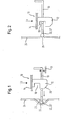
- Figur 2 die Baugruppe mit dem Gassackmodul aus Figur 1 im korrekt verriegelten Zustand.
- In Figur 1 ist eine Baugruppe mit einem Gassackmodul 10 dargestellt. Es ist eine Rastverbindung zwischen einem Gassackmodul 10 und einem fahrzeugfesten Bauteil 11 gezeigt. Das Gassackmodul 10 ist lediglich durch eines seiner ersten Rastelemente 12, hier einen Rasthaken, sowie eine damit verbundene Bodenplatte 14, z.B. einem Generatorträger, eines nicht näher dargestellten, bekannten Modulgehäuses angedeutet. Im Modulgehäuse befinden sich ein (nicht gezeigter) gefalteter Gassack sowie ein (ebenfalls nicht gezeigter) Gasgenerator, der Füllgas für das Aufblasen des Gassacks bereitstellt. Auch das fahrzeugfeste Bauteil 11 ist nur schematisch gezeigt. Hier kann es sich z.B. um eine Nabe eines Lenkrads, eine Montageplatte vorderhalb der Lenkradnabe oder einen Abschnitt einer Instrumententafel handeln. Dies alles sind bekannte Elemente, auf die hier nicht weiter eingegangen wird.
- Am fahrzeugfesten Bauteil 11 ist ein zweites Rastelement 16 befestigt. Das zweite Rastelement 16, hier ein Federdraht, hat wenigstens einen elastisch auslenkbaren oder verschieblich angeordneten Abschnitt, der bei der Herstellung einer Rastverbindung zwischen dem ersten Rastelement 12 und dem zweiten Rastelement 16 vorübergehend zur Seite bewegt wird und schließlich mit einer Rastausnehmung 18 des ersten Rastelements 12 in Eingriff kommt. Bei dem zweiten Rastelement 16 kann es sich auch um eine starre Platte handeln, die mittels einer Feder (nicht dargestellt) in seitlicher Richtung verschiebbar beaufschlagt ist. Auch andere Formen des zweiten Rastelements 16, bei denen ein Abschnitt des zweiten Rastelements 16 auslenkbar ist, sind hier einsetzbar.
- Zur Herstellung der Rastverbindung wird das Gassackmodul 10 in z-Richtung auf das zweite Rastelement 16 zu bewegt. Hierbei kommt eine Anlaufschräge 20 des ersten Rastelements 12 in Kontakt mit dem verschiebbaren Abschnitt des zweiten Rastelements 16 und bewegt diesen zur Seite (nach links in Fig. 1, siehe Pfeil).
- Es kann nun vorkommen, daß die beiden Rastelemente 12, 16 in der in Figur 1 gezeigten Position verharren, in der sich die Rastverbindung und somit auch das Gassackmodul 10 im nicht korrekt verriegelten Zustand befindet. Das zweite Rastelement 16 ist ausgelenkt, hat aber noch nicht in die Rastausnehmung 18 des ersten Rastelements 12 eingegriffen.
- Um diesen Fall erkennen zu können, ist in der Baugruppe eine Verriegelungskontrolleinrichtung mit einem Kontrollelement 22 vorgesehen. Im hier gezeigten Beispiel ist das Kontrollelement 22 durch einen Teil des zweiten Rastelements 16, hier den am weitesten nach links ragenden Abschnitt, gebildet. Das Kontrollelement 22 folgt der seitlichen Bewegung des zweiten Rastelements 16. Befindet sich das Gassackmodul 10 im nicht korrekt verriegelten Zustand, befindet sich das Kontrollelement 22 in einer ersten Position (gezeigt in Fig. 1), nämlich seitlich nach links ausgelenkt. Das Kontrollelement 22 muß nicht einstückiger Teil des zweiten Rastelement 16 sein, es könnte auch ein separates, mit diesem gekoppeltes Bauteil 22' sein (in den Figuren durch die punktierte Linie angedeutet).
- Das Kontrollelement 22 ist so angeordnet, daß es bei seiner in Figur 1 gezeigten maximalen Auslenkung einen Abschnitt 23 eines Verkleidungsteils 24 ausbeult.
- Alternativ kann das Kontrollelement 22 auch durch eine Öffnung 26 im Verkleidungsteil 24 hindurchragen (in Fig. 1 in gestrichelten Linien gezeigt).
- Nur in dieser ersten Position drückt das Kontrollelement 22 das Verkleidungsteil 24 nach außen oder ragt durch die Öffnung 26 im Verkleidungsteil 24. Im montierten Zustand und von außen (z.B. von außerhalb des Verkleidungsteils 24), d.h. vom Fahrzeuginnenraum, gesehen befindet sich das Kontrollelement 22 jetzt in einer ersten Indikatorstellung, die einen Verriegelungszustand der Rastverbindung anzeigt. In diesem Fall zeigt es in der ersten Indikatorstellung durch die Ausbeulung des Verkleidungsteils 24 bzw. durch den durch die Öffnung 26 hindurchragenden Abschnitt des Kontrollelements 22 an, daß sich das Gassackmodul 10 im nicht korrekt verriegelten Zustand befindet.
- Durch das elastische Verkleidungsteil 24 kann die Rückstellkraft für das zweite Rastelement 16 unterstützt oder vollständig erzeugt werden.
- Das Verkleidungsteil 24 ist z.B. die äußere Verkleidung eines Nabentopfes eines Lenkrades oder die äußere Verkleidung eines Armaturenbrettes bzw. ein Teil einer Außenhaut einer Sitzrückenlehne. In jedem Fall ist der Abschnitt 23 des Verkleidungsteils 24 von außen, d.h. von außerhalb der Verkleidung vom Fahrzeuginneren her, einsehbar oder ertastbar.
- Im korrekt verriegelten Zustand des Gassackmoduls 10, der in Figur 2 gezeigt ist, greift hingegen der bewegliche Abschnitt des zweiten Rastelements 16 in die Rastausnehmung 18 des ersten Rastelements 12 ein. Gegenüber der in Figur 1 gezeigten Situation hat sich der bewegliche Abschnitt des zweiten Rastelements 16 wieder nach rechts verschoben. Hierdurch ist jetzt das Kontrollelement 22 in seiner zweiten Position, in der es das Verkleidungsteil 24 nicht ausbeult bzw. nicht durch die Öffnung 26 im Verkleidungsteil 24 hindurchragt.
- Im montierten Zustand und von außen, d.h. vom Fahrzeuginnenraum, gesehen befindet sich das Kontrollelement 22 jetzt in einer zweiten Indikatorstellung, die einen Verriegelungszustand der Rastverbindung anzeigt, in diesem Fall, daß sich das Gassackmodul 10 im korrekt verriegelten Zustand befindet.
- Natürlich könnte das Kontrollelement 22 auch so ausgebildet und angeordnet sein, daß die Situation umgekehrt ist: dann würde im korrekt verriegelten Zustand (was der zweiten Indikatorstellung entspricht) das Kontrollelement 22 bzw. das Bauteil 22' das Verkleidungsteil 24 ausbeulen oder durch die Öffnung 26 ragen, während im nicht korrekt verriegelten Zustand (was der ersten Indikatorstellung enspricht) das Kontrollelement 22 bzw. das Bauteil 22' nicht ertastbar oder nicht sichtbar wäre. In jedem Fall ist die zweite Indikatorstellung von der ersten verschieden.
- Es wäre auch denkbar, das Kontrollelement 22 entfernbar zu gestalten. Hier bietet es sich an, als Kontrollelement 22 wie oben beschrieben ein separates Bauteil 22' zu verwenden. Bei korrekt verriegeltem Gassackmodul 10 befindet sich dann das Kontrollelement 22 in der ersten Stellung, in der es durch die Öffnung 26 ragt und kann aus dem Gassackmodul entfernt werden. Hier ist es natürlich auch möglich, eine Kodierung vorzusehen, um später einen Nachweis darüber zu führen, daß diese spezielle Rastverbindung korrekt verriegelt war.
- Wenn das Kontrollelement 22 das Verkleidungsteil 24 auslenkt oder ausbeult, ist das Verkleidungsteil 24 vorzugsweise flexibel aus Polyurethan ausgebildet.
- Selbstverständlich könnte auch umgekehrt das erste Rastelement 12 verschieblich oder auslenkbar und das zweite Rastelement 16 fest angeordnet sein. In diesem Fall könnte das Kontrollelement 22 am ersten Rastelement 12 ausgebildet bzw. mit diesem gekoppelt sein. Ebenso lassen sich beide Rastelemente 12, 16 auslenkbar oder verschieblich ausbilden. Auch eine vertikale Auslenkung des ersten bzw. zweiten Rastelements 12, 16 wäre ausnutzbar.
- Auch wenn in der beschriebenen Ausführungsform das zweite Rastelement 16 am fahrzeugfesten Bauteil 11 angeordnet gezeigt ist, liegt es natürlich im Ermessen des Fachmanns, die Rastelemente 12, 16 auszutauschen und das zweite Rastelement 16 statt dessen am Gassackmodul 10 anzuordnen.
Claims (9)
- Baugruppe mit einem Gassackmodul und einer Verriegelungskontrolleinrichtung,mit einem ersten Rastelement (12), das zum Eingriff in ein zweites Rastelement (16) zur Bildung einer Rastverbindung zur Befestigung des Gassackmoduls (10) an einem fahrzeugfesten Bauteil (11) ausgebildet ist,
wobei das Gassackmodul (10) einen nicht korrekt verriegelten Zustand einnehmen kann, in dem das erste Rastelement (12) und das zweite Rastelement (16) in Kontakt miteinander, aber nicht in korrektem Eingriff sind, und einen korrekt verriegelten Zustand, in dem das erste Rastelement (12) in Eingriff mit dem zweiten Rastelement (16) ist,
dadurch gekennzeichnet, daß die Verriegelungskontrolleinrichtung ein beweglich angeordnetes Kontrollelement (22) umfaßt, und ein Abschnitt des Kontrollelements (22) im nicht korrekt verriegelten Zustand des Gassackmoduls (10) eine erste Position einnimmt und im korrekt verriegelten Zustand des Gassackmoduls (10) eine zweite Position einnimmt und
das Kontrollelement (22) in der ersten Position im montierten Zustand und von außen gesehen eine erste Indikatorstellung und in der zweiten Position eine von der ersten Indikatorstellung verschiedene zweite Indikatorstellung einnimmt und eine Anzeige für ein sich nicht im korrekt verriegelten Zustand befindendes Gassackmodul (10) bildet. - Baugruppe nach Anspruch 1, dadurch gekennzeichnet, daß das Kontrollelement (22) nur in der ersten oder nur in der zweiten Position einen Abschnitt eines Verkleidungsteils (24) nach außen drückt.
- Baugruppe nach Anspruch 1, dadurch gekennzeichnet, daß das Kontrollelement (22) nur in der ersten oder nur in der zweiten Position durch eine Öffnung (26) in einem Verkleidungsteil (24) hindurchragt.
- Baugruppe nach einem der vorhergehenden Ansprüche, dadurch gekennzeichnet, daß das Kontrollelement (22) durch einen Abschnitt des zweiten Rastelements (16) gebildet ist.
- Baugruppe nach einem der Ansprüche 1 bis 3, dadurch gekennzeichnet, daß das Kontrollelement (22) durch ein separates, mit dem zweiten Rastelement (16) gekoppeltes Bauteil (22') gebildet ist.
- Baugruppe nach einem der vorhergehenden Ansprüche, dadurch gekennzeichnet, daß das zweite Rastelement (16) verschieblich angeordnet ist.
- Baugruppe nach einem der vorhergehenden Ansprüche, dadurch gekennzeichnet, daß das zweite Rastelement (16) ein Federdraht oder eine Platte ist.
- Baugruppe nach einem der vorhergehenden Ansprüche, dadurch gekennzeichnet, daß das zweite Rastelement (16) bei der Herstellung der Rastverbindung (12, 16) seitlich ausgelenkt wird und im nicht korrekt verriegelten Zustand des Gassackmoduls (10) diese Auslenkung bestehen bleibt.
- Baugruppe nach einem der vorhergehenden Ansprüche, dadurch gekennzeichnet, daß das Gassackmodul (10) in ein Lenkrad eingesetzt ist.
Applications Claiming Priority (1)
| Application Number | Priority Date | Filing Date | Title |
|---|---|---|---|
| DE202005019961U DE202005019961U1 (de) | 2005-12-21 | 2005-12-21 | Gassackmodul mit Verriegelungskontrolleinrichtung |
Publications (3)
| Publication Number | Publication Date |
|---|---|
| EP1800968A2 true EP1800968A2 (de) | 2007-06-27 |
| EP1800968A3 EP1800968A3 (de) | 2007-08-08 |
| EP1800968B1 EP1800968B1 (de) | 2010-02-24 |
Family
ID=36274276
Family Applications (1)
| Application Number | Title | Priority Date | Filing Date |
|---|---|---|---|
| EP06025113A Not-in-force EP1800968B1 (de) | 2005-12-21 | 2006-12-05 | Baugruppe mit einem Gassackmodul und einer Verriegelungskontrolleinrichtung |
Country Status (3)
| Country | Link |
|---|---|
| US (1) | US7597344B2 (de) |
| EP (1) | EP1800968B1 (de) |
| DE (2) | DE202005019961U1 (de) |
Families Citing this family (3)
| Publication number | Priority date | Publication date | Assignee | Title |
|---|---|---|---|---|
| DE102007056227A1 (de) * | 2007-11-22 | 2009-06-04 | Continental Automotive Gmbh | Airbag-Satellit |
| US9783147B2 (en) * | 2015-08-18 | 2017-10-10 | Key Safety Systems, Inc. | Driver air bag with snap-in attachment mechanism |
| DE102020117454A1 (de) | 2020-07-02 | 2022-01-05 | Bayerische Motoren Werke Aktiengesellschaft | Verfahren zur Überwachung einer wenigstens einen Clipkörper umfassenden Clipverbindung an einem Bauteil |
Family Cites Families (10)
| Publication number | Priority date | Publication date | Assignee | Title |
|---|---|---|---|---|
| US4974873A (en) * | 1987-02-26 | 1990-12-04 | Honda Giken Kogyo Kabushiki Kaisha | Malfunction preventing device for air bag module in automobiles |
| US5505483A (en) * | 1993-04-28 | 1996-04-09 | Nippondenso Co., Ltd. | Airbag safety module for vehicle |
| US5380037A (en) * | 1993-10-25 | 1995-01-10 | General Motors Corporation | Snap-in inflatable restraint module mounting mechanism including latch elements |
| DE19854335A1 (de) | 1998-11-25 | 2000-06-15 | Autoliv Dev | Clipsverbindung mit Verriegelungsabfrage |
| DE19927032A1 (de) * | 1999-06-04 | 2000-12-14 | Petri Ag | Anordnung zur Verrastung eines Airbagmoduls mit einem Lenkrad |
| DE20017527U1 (de) * | 2000-10-12 | 2001-02-22 | TRW Automotive Safety Systems GmbH & Co. KG, 63743 Aschaffenburg | Fahrzeuglenkrad |
| GB2383301A (en) * | 2001-12-18 | 2003-06-25 | Autoliv Dev | Air bag unit with locating means |
| DE20204461U1 (de) | 2002-03-20 | 2002-07-25 | TRW Automotive Safety Systems GmbH & Co. KG, 63743 Aschaffenburg | Baugruppe mit Rastelementen |
| DE20219124U1 (de) * | 2002-12-10 | 2003-04-17 | TRW Automotive Safety Systems GmbH, 63743 Aschaffenburg | Kontrollsystem für Rastverbindungen |
| DE202005020078U1 (de) * | 2005-12-21 | 2006-02-16 | Trw Automotive Safety Systems Gmbh | Gassackmodul |
-
2005
- 2005-12-21 DE DE202005019961U patent/DE202005019961U1/de not_active Expired - Lifetime
-
2006
- 2006-12-05 DE DE502006006231T patent/DE502006006231D1/de active Active
- 2006-12-05 EP EP06025113A patent/EP1800968B1/de not_active Not-in-force
- 2006-12-15 US US11/639,702 patent/US7597344B2/en active Active
Non-Patent Citations (1)
| Title |
|---|
| None |
Also Published As
| Publication number | Publication date |
|---|---|
| DE202005019961U1 (de) | 2006-04-13 |
| US7597344B2 (en) | 2009-10-06 |
| EP1800968A3 (de) | 2007-08-08 |
| EP1800968B1 (de) | 2010-02-24 |
| DE502006006231D1 (de) | 2010-04-08 |
| US20070138770A1 (en) | 2007-06-21 |
Similar Documents
| Publication | Publication Date | Title |
|---|---|---|
| DE102017117534A1 (de) | Sitzschienenmodul für einen Fahrzeugsitz zur Fahrzeugsitzverzögerung im Crashfall | |
| DE102008015188A1 (de) | Fahrzeugüberkopfkonsolenvorrichtung mit einer absenkbaren Fahrzeuginsassenspiegelvorrichtung | |
| DE202014002194U1 (de) | Verbinderbauteil zur Befestigung eines Gassackmoduls an einem Lenkrad, Positionierhülse dafür, Set mit einem solchen Verbinderbauteil und einer Positionierhülse sowie Lenkrad, Gassackmodul und Lenkradbaugruppe | |
| EP1800968B1 (de) | Baugruppe mit einem Gassackmodul und einer Verriegelungskontrolleinrichtung | |
| DE19621397B4 (de) | Airbagmodul | |
| WO2018188885A1 (de) | Gassackmodul, lenkrad und verfahren zum verbinden eines gassackmoduls mit einem lenkrad | |
| DE102022119183B4 (de) | Kraftfahrzeugsitz mit einer beleuchtbaren Blende und Kraftfahrzeug mit einem solchen Kraftfahrzeugsitz | |
| DE102017117272A1 (de) | Gurtstraffer für einen Sicherheitsgurt eines Fahrzeuges | |
| DE60102092T2 (de) | Schaltereinheit für ein Lenkrad in einem Kraftfahrzeug | |
| DE102013011811A1 (de) | Gassackbaugruppe und lenkradbaugruppe | |
| DE202006020577U1 (de) | Baugruppe mit einer Instrumententafel für Kraftfahrzeuge und einem Kniegassack | |
| EP1407945A2 (de) | Magnetischer Positionssensor | |
| DE202011001896U1 (de) | Vorrichtung zur Sitzbelegungserfassung für Fahrzeugsitze | |
| DE202015001912U1 (de) | Sitzbelegungssensoreinheit und Sitz | |
| EP1350962B1 (de) | Baugruppe mit Rastelementen | |
| DE202021105623U1 (de) | Fahrzeugcockpit-Modulanordnung | |
| DE102011120490A1 (de) | Anordnung eines Lenkrades und eines mit diesem verbundenen Airbag-Moduls bei einem Kraftfahrzeug | |
| DE10307535A1 (de) | Baugruppe für eine Sicherheitsgurtanordnung | |
| EP0284723B1 (de) | Automobil-Lenkschloss | |
| DE60109116T2 (de) | Kraftfahrzeugausrüstung enthaltend verbesserte Befestigungs- und elektrische Verbindungsmittel | |
| DE102011050151A1 (de) | Anordnung für einen Verstellmechanismus im Kfz-Bereich sowie ein Verfahren zur Verstellung eines derartigen Verstellmechanismus | |
| DE202005020078U1 (de) | Gassackmodul | |
| DE102009007401B4 (de) | Gassackmodul mit Hupenkontakt | |
| DE202011109930U1 (de) | Lenkrad für ein Kraftfahrzeug | |
| DE102015221572A1 (de) | Antriebseinrichtung für ein Gurtschloss einer Sicherheitsgurteinrichtung |
Legal Events
| Date | Code | Title | Description |
|---|---|---|---|
| PUAI | Public reference made under article 153(3) epc to a published international application that has entered the european phase |
Free format text: ORIGINAL CODE: 0009012 |
|
| AK | Designated contracting states |
Kind code of ref document: A2 Designated state(s): AT BE BG CH CY CZ DE DK EE ES FI FR GB GR HU IE IS IT LI LT LU LV MC NL PL PT RO SE SI SK TR |
|
| AX | Request for extension of the european patent |
Extension state: AL BA HR MK YU |
|
| PUAL | Search report despatched |
Free format text: ORIGINAL CODE: 0009013 |
|
| AK | Designated contracting states |
Kind code of ref document: A3 Designated state(s): AT BE BG CH CY CZ DE DK EE ES FI FR GB GR HU IE IS IT LI LT LU LV MC NL PL PT RO SE SI SK TR |
|
| AX | Request for extension of the european patent |
Extension state: AL BA HR MK YU |
|
| 17P | Request for examination filed |
Effective date: 20080204 |
|
| AKX | Designation fees paid |
Designated state(s): DE ES FR IT |
|
| GRAP | Despatch of communication of intention to grant a patent |
Free format text: ORIGINAL CODE: EPIDOSNIGR1 |
|
| GRAS | Grant fee paid |
Free format text: ORIGINAL CODE: EPIDOSNIGR3 |
|
| GRAA | (expected) grant |
Free format text: ORIGINAL CODE: 0009210 |
|
| AK | Designated contracting states |
Kind code of ref document: B1 Designated state(s): DE ES FR IT |
|
| REF | Corresponds to: |
Ref document number: 502006006231 Country of ref document: DE Date of ref document: 20100408 Kind code of ref document: P |
|
| REG | Reference to a national code |
Ref country code: DE Ref legal event code: R096 Ref document number: 502006006231 Country of ref document: DE Effective date: 20100408 |
|
| PG25 | Lapsed in a contracting state [announced via postgrant information from national office to epo] |
Ref country code: ES Free format text: LAPSE BECAUSE OF FAILURE TO SUBMIT A TRANSLATION OF THE DESCRIPTION OR TO PAY THE FEE WITHIN THE PRESCRIBED TIME-LIMIT Effective date: 20100604 |
|
| PLBE | No opposition filed within time limit |
Free format text: ORIGINAL CODE: 0009261 |
|
| STAA | Information on the status of an ep patent application or granted ep patent |
Free format text: STATUS: NO OPPOSITION FILED WITHIN TIME LIMIT |
|
| 26N | No opposition filed |
Effective date: 20101125 |
|
| REG | Reference to a national code |
Ref country code: DE Ref legal event code: R097 Ref document number: 502006006231 Country of ref document: DE Effective date: 20101125 |
|
| PG25 | Lapsed in a contracting state [announced via postgrant information from national office to epo] |
Ref country code: IT Free format text: LAPSE BECAUSE OF FAILURE TO SUBMIT A TRANSLATION OF THE DESCRIPTION OR TO PAY THE FEE WITHIN THE PRESCRIBED TIME-LIMIT Effective date: 20100224 |
|
| PGFP | Annual fee paid to national office [announced via postgrant information from national office to epo] |
Ref country code: FR Payment date: 20120104 Year of fee payment: 6 |
|
| REG | Reference to a national code |
Ref country code: FR Ref legal event code: ST Effective date: 20130830 |
|
| PG25 | Lapsed in a contracting state [announced via postgrant information from national office to epo] |
Ref country code: FR Free format text: LAPSE BECAUSE OF NON-PAYMENT OF DUE FEES Effective date: 20130102 |
|
| REG | Reference to a national code |
Ref country code: DE Ref legal event code: R081 Ref document number: 502006006231 Country of ref document: DE Owner name: ZF AUTOMOTIVE SAFETY GERMANY GMBH, DE Free format text: FORMER OWNER: TRW AUTOMOTIVE SAFETY SYSTEMS GMBH, 63743 ASCHAFFENBURG, DE Ref country code: DE Ref legal event code: R082 Ref document number: 502006006231 Country of ref document: DE Representative=s name: MEHNERT, BERNHARD, DE |
|
| P01 | Opt-out of the competence of the unified patent court (upc) registered |
Effective date: 20230628 |
|
| PGFP | Annual fee paid to national office [announced via postgrant information from national office to epo] |
Ref country code: DE Payment date: 20231231 Year of fee payment: 18 |
|
| REG | Reference to a national code |
Ref country code: DE Ref legal event code: R119 Ref document number: 502006006231 Country of ref document: DE |
|
| PG25 | Lapsed in a contracting state [announced via postgrant information from national office to epo] |
Ref country code: DE Free format text: LAPSE BECAUSE OF NON-PAYMENT OF DUE FEES Effective date: 20250701 |