EP1800902B1 - Radialluftreifen - Google Patents
Radialluftreifen Download PDFInfo
- Publication number
- EP1800902B1 EP1800902B1 EP05788069A EP05788069A EP1800902B1 EP 1800902 B1 EP1800902 B1 EP 1800902B1 EP 05788069 A EP05788069 A EP 05788069A EP 05788069 A EP05788069 A EP 05788069A EP 1800902 B1 EP1800902 B1 EP 1800902B1
- Authority
- EP
- European Patent Office
- Prior art keywords
- tire
- organic fiber
- belt
- layer
- pneumatic radial
- Prior art date
- Legal status (The legal status is an assumption and is not a legal conclusion. Google has not performed a legal analysis and makes no representation as to the accuracy of the status listed.)
- Not-in-force
Links
- 239000000835 fiber Substances 0.000 claims description 145
- 239000004760 aramid Substances 0.000 claims description 25
- 229920003235 aromatic polyamide Polymers 0.000 claims description 25
- 239000004953 Aliphatic polyamide Substances 0.000 claims description 18
- 229920003231 aliphatic polyamide Polymers 0.000 claims description 18
- 239000011324 bead Substances 0.000 claims description 10
- 230000007423 decrease Effects 0.000 claims 1
- 230000000694 effects Effects 0.000 description 24
- 229920001778 nylon Polymers 0.000 description 15
- 239000004677 Nylon Substances 0.000 description 14
- 229920000271 Kevlar® Polymers 0.000 description 13
- 239000004761 kevlar Substances 0.000 description 13
- 230000001629 suppression Effects 0.000 description 8
- 230000003247 decreasing effect Effects 0.000 description 7
- 238000012360 testing method Methods 0.000 description 6
- 230000035515 penetration Effects 0.000 description 5
- 238000004073 vulcanization Methods 0.000 description 5
- 230000000052 comparative effect Effects 0.000 description 4
- 239000000463 material Substances 0.000 description 4
- 229920002302 Nylon 6,6 Polymers 0.000 description 3
- 230000001771 impaired effect Effects 0.000 description 3
- 238000004519 manufacturing process Methods 0.000 description 3
- 238000004804 winding Methods 0.000 description 3
- 238000004364 calculation method Methods 0.000 description 2
- 238000010073 coating (rubber) Methods 0.000 description 2
- 238000013461 design Methods 0.000 description 2
- 230000020169 heat generation Effects 0.000 description 2
- 229920002647 polyamide Polymers 0.000 description 2
- 238000012545 processing Methods 0.000 description 2
- 230000002250 progressing effect Effects 0.000 description 2
- 238000000926 separation method Methods 0.000 description 2
- 241000254043 Melolonthinae Species 0.000 description 1
- 239000004952 Polyamide Substances 0.000 description 1
- 230000002159 abnormal effect Effects 0.000 description 1
- 239000011248 coating agent Substances 0.000 description 1
- 238000000576 coating method Methods 0.000 description 1
- 238000011161 development Methods 0.000 description 1
- 238000000034 method Methods 0.000 description 1
- 238000004064 recycling Methods 0.000 description 1
- 230000001105 regulatory effect Effects 0.000 description 1
- 230000003252 repetitive effect Effects 0.000 description 1
- 238000009941 weaving Methods 0.000 description 1
- 239000013585 weight reducing agent Substances 0.000 description 1
Images


Classifications
-
- B—PERFORMING OPERATIONS; TRANSPORTING
- B60—VEHICLES IN GENERAL
- B60C—VEHICLE TYRES; TYRE INFLATION; TYRE CHANGING; CONNECTING VALVES TO INFLATABLE ELASTIC BODIES IN GENERAL; DEVICES OR ARRANGEMENTS RELATED TO TYRES
- B60C11/00—Tyre tread bands; Tread patterns; Anti-skid inserts
- B60C11/03—Tread patterns
- B60C11/0327—Tread patterns characterised by special properties of the tread pattern
- B60C11/0332—Tread patterns characterised by special properties of the tread pattern by the footprint-ground contacting area of the tyre tread
-
- B—PERFORMING OPERATIONS; TRANSPORTING
- B60—VEHICLES IN GENERAL
- B60C—VEHICLE TYRES; TYRE INFLATION; TYRE CHANGING; CONNECTING VALVES TO INFLATABLE ELASTIC BODIES IN GENERAL; DEVICES OR ARRANGEMENTS RELATED TO TYRES
- B60C11/00—Tyre tread bands; Tread patterns; Anti-skid inserts
-
- B—PERFORMING OPERATIONS; TRANSPORTING
- B60—VEHICLES IN GENERAL
- B60C—VEHICLE TYRES; TYRE INFLATION; TYRE CHANGING; CONNECTING VALVES TO INFLATABLE ELASTIC BODIES IN GENERAL; DEVICES OR ARRANGEMENTS RELATED TO TYRES
- B60C9/00—Reinforcements or ply arrangement of pneumatic tyres
- B60C9/005—Reinforcements made of different materials, e.g. hybrid or composite cords
-
- B—PERFORMING OPERATIONS; TRANSPORTING
- B60—VEHICLES IN GENERAL
- B60C—VEHICLE TYRES; TYRE INFLATION; TYRE CHANGING; CONNECTING VALVES TO INFLATABLE ELASTIC BODIES IN GENERAL; DEVICES OR ARRANGEMENTS RELATED TO TYRES
- B60C9/00—Reinforcements or ply arrangement of pneumatic tyres
- B60C9/18—Structure or arrangement of belts or breakers, crown-reinforcing or cushioning layers
- B60C9/20—Structure or arrangement of belts or breakers, crown-reinforcing or cushioning layers built-up from rubberised plies each having all cords arranged substantially parallel
- B60C9/22—Structure or arrangement of belts or breakers, crown-reinforcing or cushioning layers built-up from rubberised plies each having all cords arranged substantially parallel the plies being arranged with all cords disposed along the circumference of the tyre
- B60C9/2204—Structure or arrangement of belts or breakers, crown-reinforcing or cushioning layers built-up from rubberised plies each having all cords arranged substantially parallel the plies being arranged with all cords disposed along the circumference of the tyre obtained by circumferentially narrow strip winding
-
- B—PERFORMING OPERATIONS; TRANSPORTING
- B60—VEHICLES IN GENERAL
- B60C—VEHICLE TYRES; TYRE INFLATION; TYRE CHANGING; CONNECTING VALVES TO INFLATABLE ELASTIC BODIES IN GENERAL; DEVICES OR ARRANGEMENTS RELATED TO TYRES
- B60C9/00—Reinforcements or ply arrangement of pneumatic tyres
- B60C9/18—Structure or arrangement of belts or breakers, crown-reinforcing or cushioning layers
- B60C9/26—Folded plies
- B60C9/263—Folded plies further characterised by an endless zigzag configuration in at least one belt ply, i.e. no cut edge being present
-
- B—PERFORMING OPERATIONS; TRANSPORTING
- B60—VEHICLES IN GENERAL
- B60C—VEHICLE TYRES; TYRE INFLATION; TYRE CHANGING; CONNECTING VALVES TO INFLATABLE ELASTIC BODIES IN GENERAL; DEVICES OR ARRANGEMENTS RELATED TO TYRES
- B60C9/00—Reinforcements or ply arrangement of pneumatic tyres
- B60C9/18—Structure or arrangement of belts or breakers, crown-reinforcing or cushioning layers
- B60C9/28—Structure or arrangement of belts or breakers, crown-reinforcing or cushioning layers characterised by the belt or breaker dimensions or curvature relative to carcass
-
- D—TEXTILES; PAPER
- D02—YARNS; MECHANICAL FINISHING OF YARNS OR ROPES; WARPING OR BEAMING
- D02G—CRIMPING OR CURLING FIBRES, FILAMENTS, THREADS, OR YARNS; YARNS OR THREADS
- D02G3/00—Yarns or threads, e.g. fancy yarns; Processes or apparatus for the production thereof, not otherwise provided for
- D02G3/44—Yarns or threads characterised by the purpose for which they are designed
- D02G3/48—Tyre cords
-
- B—PERFORMING OPERATIONS; TRANSPORTING
- B60—VEHICLES IN GENERAL
- B60C—VEHICLE TYRES; TYRE INFLATION; TYRE CHANGING; CONNECTING VALVES TO INFLATABLE ELASTIC BODIES IN GENERAL; DEVICES OR ARRANGEMENTS RELATED TO TYRES
- B60C2200/00—Tyres specially adapted for particular applications
- B60C2200/02—Tyres specially adapted for particular applications for aircrafts
-
- D—TEXTILES; PAPER
- D10—INDEXING SCHEME ASSOCIATED WITH SUBLASSES OF SECTION D, RELATING TO TEXTILES
- D10B—INDEXING SCHEME ASSOCIATED WITH SUBLASSES OF SECTION D, RELATING TO TEXTILES
- D10B2331/00—Fibres made from polymers obtained otherwise than by reactions only involving carbon-to-carbon unsaturated bonds, e.g. polycondensation products
- D10B2331/02—Fibres made from polymers obtained otherwise than by reactions only involving carbon-to-carbon unsaturated bonds, e.g. polycondensation products polyamides
- D10B2331/021—Fibres made from polymers obtained otherwise than by reactions only involving carbon-to-carbon unsaturated bonds, e.g. polycondensation products polyamides aromatic polyamides, e.g. aramides
Definitions
- the present invention pertains to a pneumatic radial tire, and particularly relates to a pneumatic radial tire which is suitable for airplanes, having an excellent wear resistance and thus economy, and at the same time allowing lightness to be achieved.
- the belt structure uses an organic fiber having a relatively low modulus of elasticity, such as nylon, or the like, and the width of the respective belts constituting the belt layer is substantially equivalent to the tread width, thus the belt strength of the crown center part, which is dominant on the radial expansion of the tire, is relatively low with respect to the belt strength of the crown shoulder part, which is less dominant, thus the effect of suppressing the radial expansion of the tire has been rendered small.
- the belt in the conventional structure has a substantially uniform circumferential rigidity over the entire region of the tire crown
- the radial tire as proposed in the above reference has a distribution of circumferential rigidity variation of the belt in the tread width direction, thus it has been found that, in case where the tire is manufactured with a tire mold having a geometry similar to that for conventional structure items, the tire ground contact geometry formed in case where, after the tire being filled with air to the internal pressure, a load perpendicular to the road surface is imposed is different from that of the tire of the conventional structure.
- the ground contact geometry preferably has a configuration with which the ground contact length in the circumferential direction is uniform from the crown center part to the shoulder part, or gradually decreased to the shoulder part.
- the tire wear rate depends upon whether a relative slip is generated between the tire surface and the road surface within the ground contact surface at the time of tire rotating.
- the wear rate for the tread rubber is in the negligible range, but in case where, between both, there occurs a relative slip, the wear of the rubber will progress according to the contact pressure in that portion.
- the present invention has been made in view of the above-mentioned situation, and the purpose thereof is to provide a pneumatic tire for airplanes that assures good high-speed durability and wear characteristics without its excellent durability against foreign object being impaired.
- M0 Circumferential rigidity of the main belt layer at the crown center part P0.
- M2 Circumferential rigidity of the main belt layer at a position P2 which is provides at tire width direction 2/3 of a width of the main belt layer.
- D0 Tire diameter at the tire equatorial plane when, after air being filled to a prescribed internal pressure, the internal pressure is lowered to within the range from the atmospheric pressure or more to a presasure equal to or less than 5% of the prescribed internal pressure
- d Tire radius reduction determined as a differential measured in the tire radial direction between the tread surface at the tire equatorial plane and the tread surface located at 84%-of-TW position (the position corresponding at tire width direction 84% of the width TW of the ground contact footprint produced when, after air being filled to a prescribed internal pressure as given in the TRA standard, the pneumatic tire is loaded with a prescribed load as given in the TRA standard).
- A 1.3 - 5.0 ⁇ 2 ⁇ d / D ⁇ 0 - 0.33 ⁇ M ⁇ 2 / M ⁇ 0
- A Ground contact geometry rectangle rate (L2/LO) 2d/DO: Tire diameter reduction ratio
- M2/M0 Belt circumferential rigidity ratio
- the belt circumferential rigidity mentioned here refers to the circumferential modulus of elasticity for the belt layer, and is calculated by assuming that a growth rate in a tire diameter at the center part from the state in which the tire is not assembled onto a rim to the state in which the tire is assembled onto the rim and filled with air to a prescribed internal pressure is R%, and multiplying modulus of elasticity of the cord that is determined according to a range of elongation percentage of 0 to R% (see FIG 12 ), by the number of cords (the cord count) per a unit width (herein 10 mm).
- the belt circumferential rigidity in case where the cord is inclined at an angle of ⁇ with respect to the circumferential direction is calculated by multiplying the above-mentioned rigidity per unit by cos ⁇ .
- the rigidity thereof is calculated according to the cord as embedded in the tire, i.e., as wavy patterned, instead of calculating the rigidity thereof when the cord is straightened out.
- Both the ground contact geometry rectangle rate and the prediction line correspond to each other, and the graph shows that, from a particular belt rigidity ratio and tire diameter reduction ratio, which are design factors, the rectangle rate for a tire can be predicted with high accuracy.
- the invention as stated in claim 1 has been made in view of the above-mentioned fact, and provides a pneumatic radial tire, comprising a pair of bead cores; a carcass layer made up of at least one or more carcass plies extending from one bead core toward the other bead core in the shape of a toroid; and a main belt layer which is disposed on the tire radial outer side of said carcass layer, including a plurality of organic fiber cords extending in the tire circumferential direction, wherein, when the pneumatic radial tire is assembled onto a rim, and after air being filled to a prescribed internal pressure as given in the TRA standard, the pneumatic radial tire is loaded with a prescribed load as given in the TRA standard, the width of the ground contact footprint is TW and the width of the main belt layer is BW, then the expression 0.8TW ⁇ BW ⁇ 1.2TW is satisfied; the number of plies of said main belt layer is gradually decreased from the crown center part P0 to the
- the width TW of the ground contact footprint and the width BW of the main belt layer satisfy the expression 0.8TW ⁇ BW ⁇ 1.2TW, thus while the high speed durability is ensured, the quantity of required members can be reduced.
- the number of plies of the main belt layer which is a main strength member, is substantially continuously decreased from the crown center part P0 to the shoulder part, and when the circumferential rigidity in the crown center part P0 of said main belt layer is M0 and the circumferential rigidity of the main belt layer at the position P2 which is provided at 2/3 of the width of said main belt layer is M2, the ratio M2/M0 has been specified to be a value greater than 0.2 and smaller than 0.8.
- the degree of tension at the tread rubber is lowered, thereby the resistance to penetration of a foreign object is increased, and even if a foreign object should stick into the tire, the growth of the crack can be suppressed.
- the invention as stated in claim 2 provides the pneumatic radial tire of claim 1, wherein, in the tire ground contact footprint produced when the pneumatic radial tire is assembled onto a rim, and after air being filled to a prescribed internal pressure as given in the TRA standard, the pneumatic radial tire is loaded with a prescribed load as given in the TRA standard, the ground contact length of the portion corresponding to the crown center part P0 is L0, and the ground contact length of the portion corresponding to the position at 84% in the width direction of the tire ground contact footprint is L2, the expression 0.85 ⁇ L2/L0 ⁇ 1.1 is satisfied.
- the invention as stated in claim 3 provides the pneumatic radial tire of claim 1 or claim 2, wherein said main belt layer comprises two or more belt plies which include an organic fiber cord that is spirally wound at an angle of substantially 0 degree with respect to the tire equatorial plane.
- the organic fiber cord is spirally wound to bring the cord direction close to 0 degree with respect to the circumferential direction, which allows hooping effect of the radial tire to be exerted to the maximum and the target safety factor to be achieved with a minimum quantity of members.
- the “substantially 0 degree” includes an angle of up to 2.0 deg.
- the invention as stated in claim 4 provides the pneumatic radial tire of claim 1 or claim 2, wherein said main belt layer is inclined at an angle of 2 to 25 degree with respect to the tire equatorial plane, and comprises two or more belt plies including an organic fiber cord while extending zigzag in the tire circumferential direction, being flexed in the same plane so as to incline toward the opposite direction at the respective ply ends.
- the main belt layer is provided at an angle in the range of 2 to 25 degree with respect to the tire equatorial plane, whereby the rigidity can be obtained also in the tire width direction without the hooping effect of the belt being greatly impaired, which has an effect of reducing the drag wear of the shoulder part at the time of rotating.
- the invention as stated in claim 5 provides the pneumatic radial tire of any one of claim 1 to claim 4, wherein, in said main belt layer, the layer thickness for said organic fiber cord is rendered the thickest in said crown center part P0, and when the layer thickness for said organic fiber cord in said crown center part P0 is G0, and the layer thickness for said organic fiber cord at the position P2 which is provided at 2/3 width of the maximum width of said main belt layer is G2, the expression 0.35 ⁇ G2/G0 ⁇ 0.85 is satisfied.
- the belt layer thickness is set in the above-mentioned range, whereby, in the tire center part, where the greatest effect of suppressing the tire radial expansion is obtained, a high belt rigidity can be ensured, and thus an improvement in FOD (foreign object damage) resistance can be obtained.
- G2/G0 is more than 0.85, more belt plies are disposed in the tire shoulder part, which is less effective in suppression of the tire radial expansion, thus the effect of lightweighting the tire is decreased.
- G2/G0 is less than 0.35, a sufficient belt rigidity cannot be provided for the shoulder part, thus at the time of high speed running, a standing wave tends to be generated, which is unpreferable for durability.
- the invention as stated in claim 6 provides the pneumatic radial tire of any one of claim 1 to claim 5, wherein said main belt layer is made up of at least two or more belt plies including an organic fiber cord which is adapted to have a tensile breaking strength of 6.3 cN/dtex or over; and to have an elongation percentage of 0.2 to 2.0% at a load of 0.3 cN/dtex in the direction of elongation; an elongation percentage of 1.5 to 7.0% at a load of 2.1 cN/dtex in the direction of elongation; and an elongation percentage of 2.2 to 9.3% at a load of 3.2 cN/dtex in the direction of elongation.
- the number of belt plies is set such that it is substantially decreased from the crown center part P0 to the shoulder part, which has made it possible to suppress the tire radial expansion in the crown center part P0, however, in claim 6, an organic fiber cord having a higher elasticity is used for the belt, whereby the tire radial expansion can be more effectively suppressed.
- both radial expansion suppression and weight reduction can be achieved. If the organic fiber cord having a low elasticity as nylon is used, there arises the need for providing more plies in order to suppress the radial expansion, which leads to an increase in tire weight.
- the main belt layer is made up of at least two or more belt plies including an organic fiber cord with a high elasticity which tensile breaking strength is specified to be 6.3 cN/dtex or more, whereby the requirement for pressure resistance performance can be satisfied.
- the elongation percentage at a load of 2.1 cN/dtex in the direction of elongation to be 1.5 to 7.0%; and the elongation percentage at a load of 3.2 cN/dtex in the direction of elongation to be 2.2 to 9.3%, the suppression of the radial expansion can be achieved.
- the tire outside diameter is generally set such that the green tire is expanded by approx. 0.2 to 2.0% in the tire mold.
- the prescribed internal pressure is 1620 kPa, and the prescribed load is 24,860 kg.
- the organic fiber cord more preferably has an elongation percentage of 0.2 to 1.5% at a load of 0.3 cN/dtex in the direction of elongation; an elongation percentage of 1.5 to 6.5% at a load of 2.1 cN/dtex in the direction of elongation; and an elongation percentage of 2.2 to 8.3% at a load of 3.2 cN/dtex in the direction of elongation.
- the invention as recited in claim 7 provides the pneumatic radial tire of any one of claim 1 to claim 6, wherein said main belt layer has a belt ply including an organic fiber cord which includes an aromatic polyamide-based fiber and an aliphatic polyamide-based fiber, and the weight ratio between the aromatic polyamide-based fiber and the aliphatic polyamide-based fiber is from 100 : 10 to 100 : 170.
- the organic fiber cord in the main belt layer includes an aromatic polyamide fiber with a high modulus of elasticity and an aliphatic polyamide fiber having a large cord elongation at the time of breaking, whereby both tire radial expansion suppression and safety ensurance at the time of an abnormal load input to the tire resulting in a large cord elongation being generated, can be achieved.
- the weight ratio between the aromatic polyamide-based fiber and the aliphatic polyamide-based fiber is preferably from 100: 10 to 100 : 170.
- the aliphatic polyamide-based fiber is, for example, 6-nylon, 6,6-nylon, 4,6-nylon fibers, or the like.
- aromatic polyamide-based organic fiber cord and the aliphatic polyamide-based organic fiber cord may be twisted together, or they may be unified before being twisted.
- aromatic polyamide-based organic fiber cord is A and the aliphatic polyamide-based organic fiber cord is B
- a or B is preliminary-twisted (Z-twisted) before being neatly arranged and final-twisted (S-twisted) in the direction opposite to that for preliminary twist, whereby an organic fiber cord constituting the main belt layer can be obtained.
- a or B may be twisted alone, respectively, or A and B may be unified before being twisted.
- the number of cords of A and B, or AB (a unified yarn) at the time of preliminary twisting or final twisting may be one or more than one, respectively.
- the thread diameter for weaving for A may be the same as or different from that for B.
- the form of the mixed twisted yarn may be that in which a loop is produced around the yarn as a core, or the like.
- a first embodiment of the pneumatic radial tire of the present invention will be described with reference to FIG 1 to FIG 5 .
- a pneumatic radial tire 10 (with a tire size of 1270 x 455 R22 32PR) for airplane of the present embodiment comprises a bead core 14 having a round section at a bead part 12, and to this bead core 14, a carcass layer 16 made up of six carcass plies (not shown) in which rubber-coated organic fiber cords are arranged in the radial direction is anchored.
- the other structural members such as a flipper, a chafer, and the like, are the same as those in the conventional pneumatic radial tire, and illustration of them is omitted.
- a side rubber layer 27 constituting a side wall part 25 is provided on the tire width direction outer side of the carcass layer.
- the belt layer 20 is made up of a main belt layer 26 provided at inner side in the tire radial direction and a protection belt layer 22 provided at outer side of the main belt layer 26.
- the organic fiber cord to be used for the carcass ply constituting the carcass layer 16 preferably has a tensile breaking strength of 6.3 cN/dtex or more; an elongation percentage of 0.2 to 1.8% at a load of 0.2 cN/dtex in the direction of elongation; an elongation percentage of 1.4 to 6.4% at a load of 1.9 cN/dtex in the direction of elongation; an elongation percentage of at a load of 2.1 to 8.6% at a load of 2.9 cN/dtex in the direction of elongation (see FIG 14 ).
- an organic fiber cord made up of an aromatic polyamide-based fiber can be used as the carcass layer 16.
- the organic fiber cord preferably has a preliminary twist factor of 0.12 to 0.85, and more preferably of 0.17 to 0.51, and a final twist factor of 0.4 to 0.85.
- an organic fiber cord (a so-called hybrid cord) comprising an aromatic polyamide-based fiber and an aliphatic polyamide-based fiber can also be used.
- the organic fiber cord preferably has a weight ratio of the aromatic polyamide-based fiber to the aliphatic polyamide-based fiber from 100 : 27 to 100 : 255.
- an organic fiber cord (a so-called hybrid cord) with which an aromatic polyamide-based organic fiber cord and an aliphatic polyamide-based organic fiber cord are twisted together, and the polyamide-based organic fiber cord has a preliminary twist factor N1 of 0.12 to 0.85 and more preferably of 0.17 to 0.51 can also be used.
- a nylon cord is used for the carcass layer 16 in the present embodiment.
- the main belt layer 26 is made up of a plurality of belt plies, i.e., in the present embodiment, nine belt plies in total of a first belt ply 26A, a second belt ply 26B, a third belt ply 26C, a fourth belt ply 26D, a fifth belt ply 26E, a sixth belt ply 26F, a seventh belt ply 26G, an eighth belt ply 26H, and a ninth belt ply 26I from inner side in the tire radial direction.
- the first belt ply 26A and the second belt ply 26B are set to have the same width; the third belt ply 26C and the fourth belt ply 26D are set to have the same width; the fifth belt ply 26E and the sixth belt ply 26F are set to have the same width; and the seventh belt ply 26G and the eighth belt ply 26H are set to have the same width.
- the belt width of the third belt ply 26C and the fourth belt ply 26D is set wider than that of the first belt ply 26A and the second belt ply 26B; the belt width of the fifth belt ply 26E and the sixth belt ply 26F is set wider than that of the third belt ply 26C and the fourth belt ply 26D; and the belt width of the seventh belt ply 26G and the eighth belt ply 26H is set wider than that of the fifth belt ply 26E and the sixth belt ply 26F.
- These first belt ply 26A to eighth belt ply 26H constituting the main belt layer 26 are formed by rubber-coating a plurality of organic fiber cords.
- the organic fiber cord of these first belt ply 26A to eighth belt ply 26H preferably has a tensile breaking strength of 6.3 cN/dtex or more; and preferably has an elongation percentage of 0.2 to 2.0% at a load of 0.3 cN/dtex in the direction of elongation; an elongation percentage of 1.5 to 7.0% at a load of 2.1 cN/dtex in the direction of elongation; and an elongation percentage of 2.2 to 9.3% at a load of 3.2 cN/dtex in the direction of elongation.
- the organic fiber cord in the present embodiment is made up of an aromatic polyamide-based fiber.
- the organic fiber cord is made up of an aromatic polyamide-based fiber
- an organic fiber cord made up of an aromatic polyamide-based fiber, specifically a polyamide fiber manufactured by DuPont (Product type name: KEVLAR(R) 29, with a nominal fineness of 3000 denier; hereinafter it may be called Kevlar as appropriate) is used.
- the twisted cord was dip-processed to produce a dipped cord.
- the tensile breaking strength of the dipped cord was determined using a testing machine (Autograph, manufactured by Shimadzu Corporation) to obtain a value of 14 cN/dtex.
- the strength of the organic fiber cord (Kevlar cord) which was used for the first belt ply 26A to the eighth belt ply 26G is 1400 N.
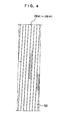
- the first belt ply 26A to the eighth belt ply 26H constituting the main belt layer 26 is a spiral belt which is formed by preparing a strip-like slender element 32 configured by rubber-coating a plurality of organic fiber cords as shown in FIG 4 , and spirally winding this slender element 32 so as not to produce any clearance.
- the inclination angle for the organic fiber cord is substantially 0 degree with respect to the tire equatorial plane CL.
- the count for the organic fiber cord is preferably in the range of 4 to 10 per 10 mm.
- the count for the organic fiber cord is 6.3 per 10 mm.
- the ninth belt ply 26I in the present embodiment is formed by preparing a strip-like slender element 34 configured by rubber-coated one or a plurality of organic fiber cords, winding this slender element 34 in the tire circumferential direction with an inclination at an angle of 2 to 25 degree with respect to the tire equatorial plane CL, while reciprocating the slender element 34 by once between both ply ends substantially in every one rounding around the tire circumference, and carrying out such winding at a number of times in the circumferential direction while shifting by substantially the width of the slender element 34 so as not to produce a clearance between slender elements 34 (hereinafter it may be called an endless zigzag wound belt).
- the organic fiber cord which extends substantially in the tire circumferential direction while zigzagging with the folding direction being changed at both ply ends is uniformly embedded over the entire region of the ninth belt ply 261.
- the ninth belt ply 26I thus formed provides a form with which organic fiber cord portions extending in a right upward direction and in a left upward direction with respect to the tire width direction are put one upon another when viewed by the section, which thus provides a configuration equivalent to a so-called cross belt with which a belt ply made up of only the right upward cord and a belt ply made up of only the left upward cord are put one upon another, thus although the ninth belt ply 26I actually provides a single ply, the number of plies for it shall be counted as two in the present embodiment.
- this ninth belt ply 26I it is preferable to use an organic fiber cord having a modulus of elasticity equivalent to or smaller than that of the organic fiber cord included in the first belt ply 26A to the eighth belt ply 26H (an organic fiber cord having an elongation percentage at a load of 2.1 cN/dtex that is substantially equivalent to or higher than that for the organic fiber cord used in the first belt ply 26A to the eighth belt ply 26H).
- a cord made up of an aliphatic polyamide-based fiber, such as nylon or the like, a cord comprising an aromatic polyamide-based fiber, such as aramid or the like, and an aliphatic polyamide-based fiber, such as nylon or the like, are preferable, and in the present embodiment, a nylon cord (1260D//2/3; count: 6.9 per 10 mm) is used.
- the inclination angle for the organic fiber cord thereof is preferably in the range of 2 to 25 degree with respect to the tire equatorial plane CL, and in the present embodiment, it is set at 8 degree.
- the protection belt layer 22 is provided through a rubber layer 30.
- the thickness of the rubber layer 30 is preferably in the range of 1.5 to 4.5 mm, and in the present embodiment, it is set at 2.5 mm.
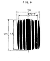
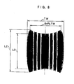
- the belt protection layer 22 is made up of one cord ply 38 with which a plurality of organic fiber cords 36 extending in wavy shape in the tire circumferential direction are arranged in parallel with one another and coated with rubber (the rubber is not shown).
- the organic fiber cord 36 in the belt protection layer 22 it is preferable to have wavy shape with a width A of 5 to 25 mm and a length B of a unit wave at 200 to 700% of the width A.
- the organic fiber cords 36 preferably have a high strength and a high cut resistance, and are arranged as tightly as possible while the bonding being ensured.
- Kevlar cord 3000D/3; count: 3.6 per 10 mm
- the pneumatic radial tire 10 when the pneumatic radial tire 10 is assembled onto a rim and is loaded with a prescribed load as given in the TRA standard after air being filled to a prescribed internal pressure as given in the TRA standard, the width of the ground contact footprint is TW, and the width of the main belt layer 26 is BW, the pneumatic radial tire 10 meets the expression 0.8TW ⁇ BW ⁇ 1.2TW
- the pneumatic radial tire 10 meets the expression 0.2 ⁇ M2/M0 ⁇ 0.8
- the main belt layer 26 is made up of a Kevlar cord and a nylon cord
- an elongation which provides a strength for a particular cord is calculated according to 10% elongation of the elongation occurred when one Kevlar cord is broken off (in case where the main belt layer 26 is made up of a plurality types of cord, the smallest breaking-off elongation is used as the reference in breaking-off elongations of respective cords).
- the strength of the respective cords when they are elongated by 10% is 1400 N for the Kevlar cord, and 205 N for the nylon cord.
- the cord count per a unit width of 10 mm is 6.2; for the ninth belt ply 26I, the cord count per a unit width of 10 mm is 6.9; and for the belt protection layer 22, the cord count per a unit width of 10 mm is 3.6.
- Kevlar cords for the first belt ply 26A to the eighth belt ply 26H
- two nylon cords for the ninth belt ply 26I
- the strength thereof is calculated in the state that the organic fiber cord as embedded in the tire, i.e., as patterned in wavy configuration is elongated by 10%, instead of calculating the strength thereof when the organic fiber cord is straightened out.
- the cord strength is multiplied by cos ⁇ to calculate the strength in the cord circumferential direction.
- the tire diameter in the tire equatorial plane CL is D0; with the position in the tread surface that corresponds to 84% of the width TW of said ground contact footprint being called a 84%-of-TW position, the tire radius reduction determined in the tire radial direction from the tread surface in the tire equatorial plane CL to the tread surface at said 84%-of-TW position is "d"; and the ground contact control index (which is expressed by 5.0 x 2d/D0 + 0.33 x M2/M0) is F, the pneumatic radial tire 10 of the present embodiment meets the expression 0.2 ⁇ F ⁇ 0.45
- the layer thickness for the organic fiber cord in the crown center part P0 is G0
- the layer thickness for the organic fiber cord at the position P2 which is provided at 2/3 in the width direction of the maximum width BW of the main belt layer 26 is G2
- the expression 0.35 ⁇ G2/G0 ⁇ 0.85 be satisfied.
- G2/G0 is set at 0.63.
- the rectangle rate L2/L0 for the pneumatic radial tire 10 preferably meets the expression 0.85 ⁇ L2/L0 ⁇ 1.1, and in the present embodiment, the rectangle rate L2/L0 is set at 0.9.
- the width TW of the ground contact footprint and the width BW of the main belt layer 26 meets the expression 0.8TW ⁇ BW ⁇ 1.2TW, thus the high speed durability is ensured, while the quantity of required members can be reduced.
- the number of plies in the main belt layer 26, which is a main strength member, is gradually decreased from the crown center part P0 to the shoulder part, and the ratio M2/M0 between the rigidity M0 in the circumferential direction at the crown center part P0 of the main belt layer 26 and the rigidity M2 in the circumferential direction at the position P2 of the main belt layer 26 which is provided at width direction 2/3 of the width of the main belt layer 26 is set at a value greater than 0.2 and smaller than 0.8, thus while the quantity of materials used for the main belt layer 26 being minimized, the tread rubber circumferential elongation amount in the circumference direction at the tread central region can be suppressed so that the growth of the tire in the circumferential direction can be suppressed at the time of air filling to a prescribed internal pressure and at the time of high speed revolution.
- the amount of circumferential elongation of the tread rubber layer 24 is suppressed, and thus the degree of tension of the tread rubber layer 24 is lowered, the resistance to penetration of a foreign object is increased, and even if a foreign object should stick into the tire, the growth of the crack can be suppressed.
- M2/M0 is over 0.8, more belt plies are disposed in the tire shoulder part, which is less contributable in suppression of the tire radial growth, thus lightweighting the tire is hindered
- ground contact control index F which represents the tire ground contact geometry
- IfF is 0.2 or less, the length of the shoulder part contacting the ground is extremely increased, thus at the time of high speed running, the amount of heat generated in that portion is increased, which affect the tire durability.
- the rectangle rate L2/L0 for the ground contact footprint is 1.1 or more, the length of the shoulder part contacting the ground is extremely increased, thus at the time of high speed running, the amount of heat generated in that portion is increased, which affect the tire durability.
- the rectangle rate L2/L0 for a ground contact footprint preferably meets the expression 0.85 ⁇ L2/L0 ⁇ 1.1.
- an aromatic polyamide-based organic fiber cord is spirally wound to bring the angle of the cord direction close to 0 deg with respect to the tire circumferential direction, thus the strength of the organic fiber cord can be utilized to the maximum to ensure the circumferential rigidity of the main belt layer 26, which allows the hoop effect of the radial tire to be exerted to the maximum and the target safety factor to be achieved with a minimum quantity of members, while lightweighting being provided.
- the organic fiber cord is provided with an angle in the range of 2 to 25 degrees with respect to the tire equatorial plane CL (an angle of 8 deg in the present embodiment), whereby the rigidity in the tire width direction can be also obtained without the hoop effect of the belt being greatly impaired, which has an effect of reducing the drag wear at the shoulder part at the time of rotating.
- the organic fiber cord in the ninth belt ply 261, which is the outermost belt ply in the main belt layer 26, is inclined at 2 to 25 degrees with respect to the tire equatorial plane CL, whereby, even if the ninth belt ply 26I is cut and a crack should initiate, the crack progresses to reach the belt end portion along the cord, thus the crack can be prevented from further progressing in the tire circumferential direction.
- the inclination angle of the organic fiber cord in the ninth belt ply 26I with respect to the tire equatorial plane CL is less than 2 degrees, in case where the tire is subjected to a damage by cut, and a crack should initiate and progresses, preventing the crack from progressing in the tire circumferential direction is affected.
- the rigidity in the tire width direction cannot be ensured, thus a drag wear tends to be produced.
- the circumferential rigidity of the belt ply is lowered, which requires the number of belt plies to be increased in order to suppress the tire expansion in the radial direction, which leads tire weight increase.
- the ninth belt ply 26I in which the organic fiber cord is extended zigzag in the tire circumferential direction, being folded in the same plane so as to incline toward the opposite direction at the respective ply ends, provides a configuration in which there is no cut end of the organic fiber cord at the ply end in the tire width direction, thus even when a great distortion is caused in the ply end portion in such a case as that where a load in the width direction is imposed on the tire, the ninth belt ply 26I is hardly separated from the cover rubber (separation between the cord cut end and the cover rubber).
- the belt protection layer 22 composed with the organic fiber cord 36 and extending in a wavy shape in the tire circumferential direction is disposed via the rubber layer 30 of 2.5 mm in thickness, thus against a stick of a foreign object, or the like, into the tread rubber layer 24, the belt protection layer 22 is deformed in the direction in which the wavy form of the organic fiber cord 36 disappears, wraps the foreign object, or the like, thus penetration of the foreign object, or the like, into the main belt layer 26 can be prevented.
- the thickness of the rubber layer 30 is less than 1.5 mm, it becomes difficult to remove the rubber layer 30 without damaging the main belt layer 26 which is provided at inner side in the radial direction of the rubber layer 30 in tire recycling.
- the thickness of the rubber layer 30 is more than 4.5 mm, not only the tire weight is increased, but also the amount of heat generated in the tread is increased, which is disadvantageous for durability.
- a width A of the wavy shape of the organic fiber cord 36 in the belt protection layer 22 is less than 5 mm and a length B of each wave shape is at more than 700% of the amplitude A
- filling the pneumatic radial tire 10 with air to the internal pressure and load imposition thereon cause the organic fiber cord 36 to be substantially elongated in the circumferential direction, thus the effect of wrapping in a foreign object at the time of penetration thereof is deteriorated.
- the width A is more than 25 mm and the length B is at less than 200% of the amplitude A, it becomes difficult to ensure a sufficient spacing between adjacent organic fiber cords 36, which makes it impossible to ensure a sufficient rubber layer between cords (a coating rubber layer for covering the organic fiber cord 36), resulting in the contact portion between the rubber layer of the belt protection layer 22 and the tread rubber layer 24 being reduced, and thus the bonding strength between the organic fiber cord 36 and the tread rubber layer 24 being lowered, which tends to cause a separation therebetween
- the belt protection layer 22 which comprises the organic fiber cord 36 is provided in the outermost layer, thus even if the tread rubber layer 24 should be so worn to cause the belt protection layer 22 to be shown up on the tread surface, no sparks will be produced as with a metallic cord.
- the ratio G2/G0 between the layer thickness G0 for the organic fiber cords in the main belt layer 26 in the crown center part P0 and the layer thickness G2 for the organic fiber cord in the main belt layer 26 at the position P2 in the width direction which is provided at 2/3 of the maximum width of the main belt layer 26 meets the expression 0.35 ⁇ G2/G0 ⁇ 0.85, whereby, in the tire center part where the greatest effect of suppressing the tire radial growth is obtained, a high belt rigidity can be ensured, and thus an improvement in FOD (foreign object damage) resistance can be obtained.
- G2/G0 is over 0.85, more belt plies are disposed in the tire shoulder part, which is less contributable in suppression of the tire radial growth, light weighting the tire is affected.
- the tensile breaking strength of the organic fiber cord constituting the first belt ply 26A to the eighth belt ply 26H in the main belt layer 26 is specified to be 6.3 cN/dtex or over, thus pressure resistance performance could have been satisfied, and the lightweighting could have also been achieved.
- the elongation percentage at a load of 0.3 cN/dtex in the direction of elongation is specified to be 0.2 to 2.0%; the elongation percentage at a load of 2.1 cN/dtex in the direction of elongation is specified to be 1.5 to 7.0%; and the elongation percentage at a load of 3.2 cN/dtex in the direction of elongation is specified to be 2.2 to 9.3%, thus the target suppression of the radial growth can be achieved. Thereby, the performance against a stick of a foreign object can be ensured, and the hoop effect by the main belt layer 26 can be rendered optimum.
- the elongation percentage for the organic fiber cord constituting the first belt ply 26A to the eighth belt ply 26H in the main belt layer 26 exceeds the above-mentioned range, the bulging in the tire radial direction at the time of air filling to the tire internal pressure cannot be effectively suppressed, and the performance against a stick of a foreign object cannot be expected.
- the elongation percentage falls below the above-mentioned range, the hoop effect of the respective belt plies is too great, which results in the carcass layer 16 being unpreferably bulged in the tire width direction more than required.
- the elongation percentage at a load of 0.3 cN/dtex for the organic fiber cord constituting the first belt ply 26A to the eighth belt ply 26H in the main belt layer 26 is specified to be 0.2 to 2.0%, thus the pneumatic radial tire 10 can be evenly elongated by the pressure applied from the inside of the raw tire at the time of vulcanization, whereby the orientations of the organic fiber cords could have been aligned, with the variation in cord provision being eliminated.
- the cord tension is increased when tire is expanded at the time of vulcanization, which unpreferably results in the organic fiber cord getting into the rubber provided inner side in the tire radial direction of the cord.
- two belt plies of the seventh belt ply 26G and the eighth belt ply 26H are layered, thus even under the condition which involves heavy tension fluctuations in the organic fiber cord in the vicinity of both ends of the tire ground contact surface in the width direction as in tire rotating, especially in case where an external force is applied in the tire width direction, the impact can be effectively distributed with the resilience thereof, thus the reliability of the pneumatic radial tire 10 under hard operating conditions is improved.
- the organic fiber cord in the first belt ply 26A to the eighth belt ply 26H constituting the main belt layer 26 is made up of an aromatic polyamide-based fiber, and the preliminary twist factor has been specified to be in the range of 0.12 to 0.85, and the final twist factor to be in the range of 0.40 to 0.80, thus the tensile breaking strength of the organic fiber cord could have been set at 6.3 cN/dtex or over, with the elongation percentage at a load of 0.3 cN/dtex in the direction of elongation having been able to be set at 0.2 to 2.0%; the elongation percentage at a load of 2.1 cN/dtex in the direction of elongation set at 1.5 to 7.0%; and the elongation percentage at a load of 3.2 cN/dtex in the direction of elongation set at 2.2 to 9.3%.
- the material of the organic fiber cord in the first belt ply 26A to the eighth belt ply 26H in the main belt layer 26 differs from that of the pneumatic radial tire 10 in the first embodiment, and the organic fiber cord used for the first belt ply 26A to the eighth belt ply 26H in the present embodiment is a so-called hybrid cord which comprises an aromatic polyamide-based fiber and an aliphatic polyamide-based fiber.
- the weight ratio between the aromatic polyamide-based fiber and the aliphatic polyamide-based fiber is preferably set from 100 : 10 to 100 : 170, and more preferably from 100 : 17 to 100 : 86.
- the tensile breaking strength can be set at 6.3 cN/dtex or more; the elongation percentage at a load of 0.3 cN/dtex in the direction of elongation can be set at 0.2 to 2.0%; the elongation percentage at a load of 2.1 cN/dtex in the direction of elongation can be set at 1.5 to 7.0%; and the elongation percentage at a load of 3.2 cN/dtex in the direction of elongation can be set at 2.2 to 9.3%.
- the preliminary twist factor for the aromatic polyamide-based organic fiber cord is preferably 0.12 to 0.85.
- a single yarn which was made by two yarns (3000 denier (3340 dtex)) of Kevlar and two yarns (1260 denier (1400 dtex)) of nylon 66 was prepared, and by using a twisting machine, it was preliminary-twisted such that the preliminary twist factor for Kevlar is 0.34, and the preliminary twist factor for nylon 66 is 0.18.
- the tensile breaking strength of the dipped cord was determined using a testing machine (Autograph, manufactured by Shimadzu Corporation) to obtain a value of 11 cN/dtex.
- the material of the organic fiber cord in the main belt layer 26 was changed over from that of the pneumatic radial tire 10 in the first embodiment, however, the same effect as that of the pneumatic radial tire 10 in the first embodiment can be obtained.
- one type of conventional example of tire, two types of comparative example tire, and three types of EXAMPLE tire to which the present invention was applied were prepared for carrying out a comparison test for wear characteristics, high speed durability, tire weight, and FOD resistance performance.
- the tire size is 1270 ⁇ 455 R22 32PR for every type.
- the pneumatic radial tire of the present invention has an excellent wear resistance, and at the same time, allows lightweighting to be achieved, thus being suitable for airplanes, which requires economical and lightweight tire.
Landscapes
- Engineering & Computer Science (AREA)
- Mechanical Engineering (AREA)
- Textile Engineering (AREA)
- Tires In General (AREA)
Claims (7)
- Radialer Luftreifen, umfassend: ein Paar Wulstkerne (14); eine Karkassenschicht (16), die aus mindestens einer oder mehreren Karkassenlagen besteht, die sich von einem Wulstkern (14) auf den anderen Wulstkern (14) zu in Form eines Toroids erstrecken; und eine Hauptgürtelschicht (26), die sich auf der in Radialrichtung gelegenen Reifenaußenseite der Karkassenschicht (16) befindet und mehrere Corde aus organischen Fasern einschließt, die sich in der zirkumferentiellen Reifenrichtung erstrecken; dadurch gekennzeichnet, dass
wenn der radiale Luftreifen direkt auf eine Felge aufgebracht wird, Luft bis zu einem vorgeschriebenen Innendruck, wie in der TRA-Norm festgelegt, eingefüllt wird, eine vorgeschriebene Belastung, wie in der TRA-Norm festgelegt, aufgebracht wird und die Breite der Bodenkontaktlauffläche TW ist und die Breite der Hauptgürtelschicht (26) BW ist, so wird dem Ausdruck 0,8 TW < BW < 1,2 TW Genüge geleistet;
die Anzahl von Lagen der Hauptgürtelschicht (26) vom Kronenmittelteil P0 zum Schulterteil allmählich abnimmt; und wenn die zirkumferentielle Steifigkeit der Hauptgürtelschicht (26) im Kronenmittelteil P0 M0 ist, so ist die zirkumferentielle Steifigkeit der Hauptgürtelschicht (26) an der Position P2, die sich bei 2/3 der Breite der Hauptgürtelschicht befindet, M2 und für das Gürtelsteifigkeitsverhältnis M2/M0 wird dem Ausdruck 0,2 < M2/M0 < 0,8 Genüge geleistet; und
wenn der Innendruck, nachdem Luft bis zu dem vorgeschriebenen Innendruck eingefüllt worden ist, auf innerhalb des Bereichs vom Luftdruck oder darüber bis zu einem Druck, der dem vorgeschriebenen Innendruck oder weniger als 5 % desselben entspricht, verringert wird, der Reifendurchmesser in der äquatorialen Reifenebene D0 ist, wobei die Position an der Profiloberfläche, die 84 % der Breite TW der Bodenkontaktlauffläche entspricht, "84 % von der TW-Position" genannt wird, die Reifenradiusverringerung, die in der Reifenradialrichtung von der Profiloberfläche in der äquatorialen Reifenebene zur Profiloberfläche an der "84 % von der TW-Position" bestimmt wird, "d" ist und der Bodenkontakt-Regelindex, der durch 5,0 x 2d/D0 + 0,33 x M2/M0 ausgedrückt wird, F ist, so wird dem Ausdruck 0,2 < F < 0,45 Genüge geleistet. - Radialer Luftreifen nach Anspruch 1, wobei, wenn im Falle der Bodenkontaktlauffläche, die gebildet wird, wenn der radiale Luftreifen auf eine Felge aufgebracht wird, und nachdem Luft bis zu dem vorgeschriebenen Innendruck, wie er in der TRA-Norm festgelegt ist, eingefüllt worden ist, der radiale Luftreifen mit der vorgeschriebenen Belastung, wie in der TRA-Norm festgelegt, belastet wird, die Bodenkontaktlänge des Abschnitts, der dem Kronenmittelteil P0 entspricht, L0 ist, und die Bodenkontaktlänge des Abschnitts, der der Position 84 % der Bodenkontaktbreite entspricht, L2 ist, so wird dem Ausdruck 0,85 < L2/L0 < 1,1 Genüge geleistet
- Luftreifen nach Anspruch 1 oder Anspruch 2, wobei die Hauptgürtelschicht (26) zwei oder mehrere Gürtellagen umfasst, die einen Cord aus organischen Fasern einschließen, der spiral in einem Winkel von im Wesentlichen 0 Grad mit Bezug auf die äquatoriale Reifenebene gewickelt ist.
- Radialer Luftreifen nach Anspruch 1 oder Anspruch 2, wobei die Hauptgürtelschicht (26) zwei oder mehrere Gürtellagen umfasst, die einen Cord aus organischen Fasern einschließen, und in einem Winkel von 2 bis 25 Grad mit Bezug auf die äquatoriale Reifenebenen geneigt ist, während sie sich in Zickzackform in der zirkumferentiellen Reifenrichtung erstreckt und in derselben Ebene gebogen wird, um auf die entgegengesetzte Richtung zu an den jeweiligen Lagenenden geneigt zu sein.
- Radialer Luftreifen nach einem der Ansprüche 1 bis 4, wobei in der Hauptgürtelschicht (26) die Schichtdicke des Cords aus organischen Fasern im Kronenmittelteil P0 am dicksten gehalten wird und wenn die Schichtdicke des Cords aus organischen Fasern an der Breitenposition P2, die 2/3 der maximalen Breite der Hauptgürtelschicht bereitstellt, G2 ist, so wird dem Ausdruck 0,35 ≤ G2/G0 ≤ 0,85 Genüge geleistet.
- Radialer Luftreifen nach einem der Ansprüche 1 bis 5, wobei die Hauptgürtelschicht (26) aus mindestens zwei oder mehreren Gürtellagen besteht, die jede einen Cord aus organischen Fasern einschließt, der dazu geeignet ist, eine Zugbruchstärke von 6,3 cN/dtex oder mehr aufzuweisen und einen Dehnungsprozentsatz von 0,2 bis 2,0 % unter einer Belastung von 0,3 cN/dtex in der Dehnungsrichtung aufzuweisen; einen Dehnungsprozentsatz von 1,5 bis 7,0 % unter einer Belastung von 2,1 cN/dtex in der Dehnungsrichtung aufzuweisen; und einen Dehnungsprozentsatz von 2,2 bis 9,3 % unter einer Belastung von 3,2 cN/dtex in der Dehnungsrichtung aufzuweisen.
- Radialer Luftreifen nach einem der Ansprüche 1 bis 6, wobei die Hauptgürtelschicht (26) eine Gürtellage aufweist, die einen Cord aus organischen Fasern einschließt, der dazu geeignet ist, eine Faser auf der Basis von aromatischem Polyamid und eine Faser auf der Basis von aliphatischem Polyamid einzuschließen und das Gewichtsverhältnis von Faser auf der Basis von aromatischem Polyamid zu der Faser auf der Basis von aliphatischem Polyamid 100 : 10 bis 100 : 170 beträgt.
Applications Claiming Priority (2)
| Application Number | Priority Date | Filing Date | Title |
|---|---|---|---|
| JP2004288488 | 2004-09-30 | ||
| PCT/JP2005/018153 WO2006035940A1 (ja) | 2004-09-30 | 2005-09-30 | 空気入りラジアルタイヤ |
Publications (3)
| Publication Number | Publication Date |
|---|---|
| EP1800902A1 EP1800902A1 (de) | 2007-06-27 |
| EP1800902A4 EP1800902A4 (de) | 2008-11-05 |
| EP1800902B1 true EP1800902B1 (de) | 2009-09-02 |
Family
ID=36119082
Family Applications (1)
| Application Number | Title | Priority Date | Filing Date |
|---|---|---|---|
| EP05788069A Not-in-force EP1800902B1 (de) | 2004-09-30 | 2005-09-30 | Radialluftreifen |
Country Status (4)
| Country | Link |
|---|---|
| US (1) | US20080277037A1 (de) |
| EP (1) | EP1800902B1 (de) |
| JP (1) | JP4635010B2 (de) |
| WO (1) | WO2006035940A1 (de) |
Families Citing this family (27)
| Publication number | Priority date | Publication date | Assignee | Title |
|---|---|---|---|---|
| US20100018628A1 (en) * | 2005-12-20 | 2010-01-28 | The Goodyear Tire & Rubber Co. | Method of manufacturing a radial aircraft tire |
| US20070137744A1 (en) * | 2005-12-20 | 2007-06-21 | Kiyoshi Ueyoko | Radial aircraft tire and method of manufacture |
| US7484545B2 (en) * | 2005-12-20 | 2009-02-03 | The Goodyear Tire & Rubber Co. | Radial tire for aircraft with specified merged cords |
| JP4963858B2 (ja) * | 2006-04-13 | 2012-06-27 | 株式会社ブリヂストン | 航空機用タイヤおよびそれの製造方法 |
| JP4810384B2 (ja) * | 2006-09-29 | 2011-11-09 | 株式会社ブリヂストン | 空気入りタイヤ |
| CN102405143B (zh) * | 2009-03-03 | 2014-02-19 | 株式会社普利司通 | 航空器用子午线轮胎 |
| USD608724S1 (en) | 2009-03-16 | 2010-01-26 | Trek Bicycle Corporation | Bicycle tire tread |
| JP5668323B2 (ja) * | 2010-05-13 | 2015-02-12 | 横浜ゴム株式会社 | 新都市交通車両用空気入りラジアルタイヤ |
| EP2610074B1 (de) * | 2010-08-27 | 2015-09-16 | Bridgestone Corporation | Radialluftreifen für flugzeuge |
| JP5739681B2 (ja) * | 2011-01-28 | 2015-06-24 | 株式会社ブリヂストン | 空気入りタイヤ |
| US20120312442A1 (en) * | 2011-06-13 | 2012-12-13 | Kiyoshi Ueyoko | Reduced weight aircraft tire |
| US20120312440A1 (en) * | 2011-06-13 | 2012-12-13 | Kiyoshi Ueyoko | Reduced weight aircraft tire |
| DE112011105525B4 (de) | 2011-08-12 | 2019-06-13 | The Yokohama Rubber Co., Ltd. | Luftreifen |
| EP3074248A4 (de) | 2013-11-27 | 2017-07-12 | Bridgestone Americas Tire Operations, LLC | Reifenkonstruktion mit einer kontinuierlichen karkassenlagenhebestruktur |
| WO2016068879A1 (en) * | 2014-10-28 | 2016-05-06 | Compagnie Generale Des Etablissements Michelin | Aircraft tire |
| EP3212439B1 (de) * | 2014-10-28 | 2018-12-05 | Compagnie Générale des Etablissements Michelin | Flugzeugreifen |
| DE102015207931A1 (de) * | 2015-04-29 | 2016-11-03 | Continental Reifen Deutschland Gmbh | Fahrzeugluftreifen mit einem Laufstreifen |
| US11827064B2 (en) | 2015-08-31 | 2023-11-28 | The Goodyear Tire & Rubber Company | Reduced weight aircraft tire |
| US10723177B2 (en) * | 2015-08-31 | 2020-07-28 | The Goodyear Tire & Rubber Company | Reduced weight aircraft tire |
| JP6635762B2 (ja) * | 2015-11-16 | 2020-01-29 | Toyo Tire株式会社 | 空気入りタイヤ |
| CN108839517B (zh) * | 2018-07-13 | 2023-10-13 | 中策橡胶集团股份有限公司 | 一种跨座式单轨车辆走行轮胎 |
| JP7129900B2 (ja) * | 2018-12-21 | 2022-09-02 | 株式会社ブリヂストン | 航空機用空気入りタイヤ |
| JP7372857B2 (ja) * | 2020-03-11 | 2023-11-01 | 株式会社ブリヂストン | 空気入りタイヤ |
| JP7386779B2 (ja) * | 2020-11-19 | 2023-11-27 | 株式会社ブリヂストン | 航空機用空気入りタイヤ |
| US20220185019A1 (en) * | 2020-12-16 | 2022-06-16 | The Goodyear Tire & Rubber Company | Tire with protective belt structure |
| CN113928059A (zh) * | 2021-11-22 | 2022-01-14 | 三角轮胎股份有限公司 | 子午线轮胎及其胎体层的接头方法 |
| US20240157734A1 (en) * | 2022-11-15 | 2024-05-16 | The Goodyear Tire & Rubber Company | Aircraft radial tire |
Family Cites Families (10)
| Publication number | Priority date | Publication date | Assignee | Title |
|---|---|---|---|---|
| GB2201925B (en) * | 1987-03-12 | 1991-02-27 | Dunlop Ltd | Radial ply tyre |
| US4893665A (en) * | 1988-02-17 | 1990-01-16 | The Goodyear Tire & Rubber Company | Cables for reinforcing deformable articles and articles reinforced by said cables |
| US5054532A (en) * | 1989-02-06 | 1991-10-08 | Bridgestone Corporation | Pneumatic tires with wavy or zigzag cord ply between belt and carcass |
| JPH05139112A (ja) * | 1991-11-15 | 1993-06-08 | Sumitomo Rubber Ind Ltd | 空気入りタイヤ |
| JP3574155B2 (ja) * | 1993-01-20 | 2004-10-06 | 株式会社ブリヂストン | 航空機用ラジアルタイヤ |
| JP3198077B2 (ja) * | 1997-06-27 | 2001-08-13 | 住友ゴム工業株式会社 | 空気入りタイヤ |
| FR2791000B1 (fr) * | 1999-03-17 | 2001-05-04 | Michelin Soc Tech | Armature de sommet de pneumatique radial |
| JP3418147B2 (ja) * | 1999-12-17 | 2003-06-16 | 住友ゴム工業株式会社 | 重荷重用タイヤ |
| WO2003061991A1 (fr) * | 2002-01-24 | 2003-07-31 | Bridgestone Corporation | Pneu radial et procede de production |
| JP4266116B2 (ja) * | 2003-02-25 | 2009-05-20 | 株式会社ブリヂストン | 航空機用重荷重用空気入りラジアルタイヤ |
-
2005
- 2005-09-30 WO PCT/JP2005/018153 patent/WO2006035940A1/ja active Application Filing
- 2005-09-30 EP EP05788069A patent/EP1800902B1/de not_active Not-in-force
- 2005-09-30 US US11/664,124 patent/US20080277037A1/en not_active Abandoned
- 2005-09-30 JP JP2006537838A patent/JP4635010B2/ja not_active Expired - Fee Related
Also Published As
| Publication number | Publication date |
|---|---|
| EP1800902A1 (de) | 2007-06-27 |
| US20080277037A1 (en) | 2008-11-13 |
| WO2006035940A1 (ja) | 2006-04-06 |
| JP4635010B2 (ja) | 2011-02-16 |
| EP1800902A4 (de) | 2008-11-05 |
| JPWO2006035940A1 (ja) | 2008-05-15 |
Similar Documents
| Publication | Publication Date | Title |
|---|---|---|
| EP1800902B1 (de) | Radialluftreifen | |
| EP1431076B1 (de) | Luftreifen mit Gürtelbandage | |
| US6257291B1 (en) | Pneumatic tyre with specified reinforcing fabric | |
| US7712499B2 (en) | Pneumatic radial tire with specified belt layer | |
| EP0335588B1 (de) | Radialer Luftreifen | |
| US8479792B2 (en) | Motorcycle tire and method for manufacturing the same | |
| KR920005419B1 (ko) | 공기 타이어 | |
| JP4627664B2 (ja) | 空気入りラジアルタイヤ | |
| JP7475108B2 (ja) | 軽量化された航空機タイヤ | |
| BRPI0720650B1 (pt) | Pneumático | |
| US7780806B2 (en) | Tire for an aircraft and method for producing the same | |
| GB2542915A (en) | Reduced weight aircraft tyre | |
| CA2153949C (en) | Bias tire having an improved crown reinforcement arrangement | |
| US20030221762A1 (en) | Steel cord, method of making the same and pneumatic tire including the same | |
| JP6998705B2 (ja) | 軽量化された航空機用タイヤ | |
| AU602626B2 (en) | A pneumatic tire | |
| WO2020054798A1 (ja) | ラジアルタイヤ | |
| CA2019800C (en) | Heavy duty, high-speed, radial tire | |
| EP3736141A1 (de) | Radialreifen | |
| EP3900955B1 (de) | Flugzeugluftreifen | |
| EP4393722A1 (de) | Luftreifen | |
| JPH0569703A (ja) | 高速重荷重用クロスプライタイヤ | |
| JPH02270605A (ja) | 空気入りタイヤ | |
| CN114633584A (zh) | 具有保护性带束层结构的轮胎 |
Legal Events
| Date | Code | Title | Description |
|---|---|---|---|
| PUAI | Public reference made under article 153(3) epc to a published international application that has entered the european phase |
Free format text: ORIGINAL CODE: 0009012 |
|
| 17P | Request for examination filed |
Effective date: 20070405 |
|
| AK | Designated contracting states |
Kind code of ref document: A1 Designated state(s): FR GB |
|
| DAX | Request for extension of the european patent (deleted) | ||
| RBV | Designated contracting states (corrected) |
Designated state(s): FR GB |
|
| A4 | Supplementary search report drawn up and despatched |
Effective date: 20081006 |
|
| GRAP | Despatch of communication of intention to grant a patent |
Free format text: ORIGINAL CODE: EPIDOSNIGR1 |
|
| GRAS | Grant fee paid |
Free format text: ORIGINAL CODE: EPIDOSNIGR3 |
|
| GRAA | (expected) grant |
Free format text: ORIGINAL CODE: 0009210 |
|
| AK | Designated contracting states |
Kind code of ref document: B1 Designated state(s): FR GB |
|
| PLBE | No opposition filed within time limit |
Free format text: ORIGINAL CODE: 0009261 |
|
| STAA | Information on the status of an ep patent application or granted ep patent |
Free format text: STATUS: NO OPPOSITION FILED WITHIN TIME LIMIT |
|
| 26N | No opposition filed |
Effective date: 20100603 |
|
| REG | Reference to a national code |
Ref country code: FR Ref legal event code: CA Effective date: 20140812 |
|
| REG | Reference to a national code |
Ref country code: FR Ref legal event code: PLFP Year of fee payment: 12 |
|
| REG | Reference to a national code |
Ref country code: FR Ref legal event code: PLFP Year of fee payment: 13 |
|
| REG | Reference to a national code |
Ref country code: FR Ref legal event code: PLFP Year of fee payment: 14 |
|
| PGFP | Annual fee paid to national office [announced via postgrant information from national office to epo] |
Ref country code: FR Payment date: 20190926 Year of fee payment: 15 |
|
| PGFP | Annual fee paid to national office [announced via postgrant information from national office to epo] |
Ref country code: GB Payment date: 20190920 Year of fee payment: 15 |
|
| GBPC | Gb: european patent ceased through non-payment of renewal fee |
Effective date: 20200930 |
|
| PG25 | Lapsed in a contracting state [announced via postgrant information from national office to epo] |
Ref country code: FR Free format text: LAPSE BECAUSE OF NON-PAYMENT OF DUE FEES Effective date: 20200930 |
|
| PG25 | Lapsed in a contracting state [announced via postgrant information from national office to epo] |
Ref country code: GB Free format text: LAPSE BECAUSE OF NON-PAYMENT OF DUE FEES Effective date: 20200930 |