EP1795831B1 - Ammonia/co2 refrigeration system - Google Patents
Ammonia/co2 refrigeration system Download PDFInfo
- Publication number
- EP1795831B1 EP1795831B1 EP05765291.9A EP05765291A EP1795831B1 EP 1795831 B1 EP1795831 B1 EP 1795831B1 EP 05765291 A EP05765291 A EP 05765291A EP 1795831 B1 EP1795831 B1 EP 1795831B1
- Authority
- EP
- European Patent Office
- Prior art keywords
- liquid
- brine
- cooler
- pump
- ammonia
- Prior art date
- Legal status (The legal status is an assumption and is not a legal conclusion. Google has not performed a legal analysis and makes no representation as to the accuracy of the status listed.)
- Expired - Lifetime
Links
Images


Classifications
-
- F—MECHANICAL ENGINEERING; LIGHTING; HEATING; WEAPONS; BLASTING
- F25—REFRIGERATION OR COOLING; COMBINED HEATING AND REFRIGERATION SYSTEMS; HEAT PUMP SYSTEMS; MANUFACTURE OR STORAGE OF ICE; LIQUEFACTION SOLIDIFICATION OF GASES
- F25B—REFRIGERATION MACHINES, PLANTS OR SYSTEMS; COMBINED HEATING AND REFRIGERATION SYSTEMS; HEAT PUMP SYSTEMS
- F25B1/00—Compression machines, plants or systems with non-reversible cycle
-
- F—MECHANICAL ENGINEERING; LIGHTING; HEATING; WEAPONS; BLASTING
- F25—REFRIGERATION OR COOLING; COMBINED HEATING AND REFRIGERATION SYSTEMS; HEAT PUMP SYSTEMS; MANUFACTURE OR STORAGE OF ICE; LIQUEFACTION SOLIDIFICATION OF GASES
- F25B—REFRIGERATION MACHINES, PLANTS OR SYSTEMS; COMBINED HEATING AND REFRIGERATION SYSTEMS; HEAT PUMP SYSTEMS
- F25B25/00—Machines, plants or systems, using a combination of modes of operation covered by two or more of the groups F25B1/00 - F25B23/00
- F25B25/005—Machines, plants or systems, using a combination of modes of operation covered by two or more of the groups F25B1/00 - F25B23/00 using primary and secondary systems
-
- F—MECHANICAL ENGINEERING; LIGHTING; HEATING; WEAPONS; BLASTING
- F25—REFRIGERATION OR COOLING; COMBINED HEATING AND REFRIGERATION SYSTEMS; HEAT PUMP SYSTEMS; MANUFACTURE OR STORAGE OF ICE; LIQUEFACTION SOLIDIFICATION OF GASES
- F25B—REFRIGERATION MACHINES, PLANTS OR SYSTEMS; COMBINED HEATING AND REFRIGERATION SYSTEMS; HEAT PUMP SYSTEMS
- F25B2309/00—Gas cycle refrigeration machines
- F25B2309/06—Compression machines, plants or systems characterised by the refrigerant being carbon dioxide
-
- F—MECHANICAL ENGINEERING; LIGHTING; HEATING; WEAPONS; BLASTING
- F25—REFRIGERATION OR COOLING; COMBINED HEATING AND REFRIGERATION SYSTEMS; HEAT PUMP SYSTEMS; MANUFACTURE OR STORAGE OF ICE; LIQUEFACTION SOLIDIFICATION OF GASES
- F25B—REFRIGERATION MACHINES, PLANTS OR SYSTEMS; COMBINED HEATING AND REFRIGERATION SYSTEMS; HEAT PUMP SYSTEMS
- F25B2400/00—General features or devices for refrigeration machines, plants or systems, combined heating and refrigeration systems or heat-pump systems, i.e. not limited to a particular subgroup of F25B
- F25B2400/16—Receivers
-
- F—MECHANICAL ENGINEERING; LIGHTING; HEATING; WEAPONS; BLASTING
- F25—REFRIGERATION OR COOLING; COMBINED HEATING AND REFRIGERATION SYSTEMS; HEAT PUMP SYSTEMS; MANUFACTURE OR STORAGE OF ICE; LIQUEFACTION SOLIDIFICATION OF GASES
- F25B—REFRIGERATION MACHINES, PLANTS OR SYSTEMS; COMBINED HEATING AND REFRIGERATION SYSTEMS; HEAT PUMP SYSTEMS
- F25B2400/00—General features or devices for refrigeration machines, plants or systems, combined heating and refrigeration systems or heat-pump systems, i.e. not limited to a particular subgroup of F25B
- F25B2400/22—Refrigeration systems for supermarkets
-
- F—MECHANICAL ENGINEERING; LIGHTING; HEATING; WEAPONS; BLASTING
- F25—REFRIGERATION OR COOLING; COMBINED HEATING AND REFRIGERATION SYSTEMS; HEAT PUMP SYSTEMS; MANUFACTURE OR STORAGE OF ICE; LIQUEFACTION SOLIDIFICATION OF GASES
- F25B—REFRIGERATION MACHINES, PLANTS OR SYSTEMS; COMBINED HEATING AND REFRIGERATION SYSTEMS; HEAT PUMP SYSTEMS
- F25B2500/00—Problems to be solved
- F25B2500/01—Geometry problems, e.g. for reducing size
-
- F—MECHANICAL ENGINEERING; LIGHTING; HEATING; WEAPONS; BLASTING
- F25—REFRIGERATION OR COOLING; COMBINED HEATING AND REFRIGERATION SYSTEMS; HEAT PUMP SYSTEMS; MANUFACTURE OR STORAGE OF ICE; LIQUEFACTION SOLIDIFICATION OF GASES
- F25B—REFRIGERATION MACHINES, PLANTS OR SYSTEMS; COMBINED HEATING AND REFRIGERATION SYSTEMS; HEAT PUMP SYSTEMS
- F25B9/00—Compression machines, plants or systems, in which the refrigerant is air or other gas of low boiling point
- F25B9/002—Compression machines, plants or systems, in which the refrigerant is air or other gas of low boiling point characterised by the refrigerant
- F25B9/008—Compression machines, plants or systems, in which the refrigerant is air or other gas of low boiling point characterised by the refrigerant the refrigerant being carbon dioxide
Definitions
- the present invention relates to a refrigeration system working on an ammonia refrigerating cycle and CO 2 refrigerating cycle, specifically relates to an ammonia refrigerating cycle, a brine cooler for cooling and liquefying CO 2 by utilizing the latent heat of vaporization of ammonia, and an ammonia/CO 2 refrigeration system having a liquid pump in a supply line for supplying to a refrigeration load side the liquefied CO 2 cooled and liquefied by said brine cooler.
- a refrigerating cycle in which an ammonia cycle and CO 2 cycle are combined and CO 2 is uses as a secondary refrigerant in a refrigeration load side, is adopted in many of ice-making factories, refrigerating storehouses, and food refrigerating factories.
- Patent Literature 1 A refrigeration system in which ammonia cycle and carbon dioxide cycle are combined is disclosed in Patent Literature 1 for example.
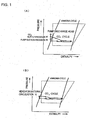
- the system is composed as shown in FIG. 11(A) .
- gaseous ammonia compressed by the compressor 104 is cooled by cooling water or air to be liquefied when the ammonia gas passes through the condenser 105.
- the liquefied ammonia is expanded at the expansion valve 106, then evaporates in the cascade condenser 107 to be gasified.
- the ammonia receives heat from the carbon dioxide in the carbon dioxide cycle to liquefy the carbon dioxide.
- the carbon dioxidecooled and liquefied in the cascade condenser 107 flows downward by its hydraulic head to pass through the flow adjusting valve 108 and enters the bottom feed type evaporator 109 to perform required cooling.
- the carbon dioxide heated and evaporated in the evaporator 109 returns again to the cascade condenser 107, thus the ammonia performs natural circulation.
- the cascade condenser 107 is located at a position higher than that of the evaporator 109, for example, located on a rooftop.
- hydraulic head is produced between the cascade condenser 107 and the evaporator 109 having a cooler fan 109a.
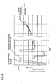
- FIG. 1 (B) is apressure-enthalpydiagram.
- the broken line shows an ammonia refrigerating cycle using a compressor
- the solid line shows a CO 2 cycle by natural circulation which is possible by composing such that there is a hydraulic head between the cascade condenser 107 and the bottom feed type evaporator 109.
- said prior art includes a fundamental disadvantage that the cascade condenser(which works as an evaporator in the ammonia cycle to cool carbon dioxide) must be located at a position higher than the position of the evaporator (refrigerating showcase, etc.) for performing required cooling in the CO 2 cycle.
- liquid pump 110 as shown in FIG.11(B) in the carbon dioxide cycle to subserve the circulation of the carbon dioxide refrigerant to ensure more positive circulation.
- the liquid pump serves only as an auxiliary means and basically natural circulation for cooling carbon dioxide is generated by the hydraulic head also in this prior art.
- a pathway provided with the auxiliary pump is added parallel to the natural circulation route on condition that the natural circulation of CO 2 is produced by the utilization of the hydraulic head. (Therefore, the pathway provided with the auxiliary pump should be parallel to the natural circulation route.)
- FIG.11(B) utilizes the liquid pump on condition that the hydraulic head is secured, that is, on condition that the cascade condenser(an evaporator for cooling carbon dioxide refrigerant) is located at a position higher than the position of the evaporator for performing cooling in the carbon dioxide cycle, and above-mentioned fundamental disadvantage is not solved also in this prior art.
- liquid CO 2 enters the cooling tube from the lower side evaporates in the cooling tube and flows upward while receiving heat, i.e. depriving heat of the air outside the cooling tube, and the evaporated gas flows upward in the cooling tube. So, in the cooling tube, the upper part is filled only with gaseous CO 2 resulting in poor cooling effect and only lower part of the cooling tube is effectively cooled. Further, when a liquid header is provided at the inlet side, uniform distribution of CO 2 in the cooling tube can not be realized. Actually, as can be seen in pressure-enthalpy diagram of FIG.1 (B) CO 2 is recovered to the cascade condenser after liquid is CO 2 perfectly evaporated.
- a refrigerating cycle using CO 2 as a secondary refrigerant for refrigerating load side is adopted very often in ice works, refrigeration warehouses, and freezing works of food.
- it is required to stop the operation of apparatus and to carry out defrosting and cleaning of the cooler(evaporator) at regular intervals or as needed from point of view of maintaining refrigerating capacity, sterilization, etc.
- temperature rise occurs naturally in the cooler(evaporator). So, if liquid CO 2 remains in the circulation path near the cooler(evaporator), there is fear that explosive vaporization(boiling) of liquid CO 2 could occur. Therefore, it is desired to withdraw the liquid CO 2 remaining near the cooler(evaporator) without delay and completely.
- Patent Literature 1 Japanese Patent No. 3458310 Document WO 02/066908 discloses a system according to the preamble of claim 1.
- the present invention was made in light of the problem mentioned above, and an object of the invention is to provide an ammonia/CO 2 refrigeration system and a CO 2 brine producing apparatus used in the system capable of constituting a cycle combining an ammonia cycle and a CO 2 cycle without problems even when the CO 2 brine producing apparatus comprising apparatuses working on an ammonia refrigerating cycle, a brine cooler for cooling and condensing CO 2 by utilizing the latent heat of vaporization of the ammonia, and a liquid pump provided in a supply line for supplying the cooled and liquefied CO 2 to a refrigeration load side, and a refrigeration load side apparatus such as for example a freezer showcase are located in any places in accordance with circumstances of customer's convenience.
- Another object of the invention is to provide a refrigeration system in which CO 2 circulation cycle can be formed irrespective of the position of the CO 2 cycle side cooler, kind thereof (bottom feed type of top feed type), and the number thereof, and further even when the CO 2 brine cooler is located at a position lower than the refrigeration load side cooler, and a CO 2 brine producing apparatus used in the system.
- a further object of the invention is to provide a refrigeration system in which withdrawal of liquid CO 2 from the CO 2 cycle is carried out without delay and completely when carrying out defrosting and cleaning of the cooler of CO 2 cycle side.
- the present invention proposes an ammonia/CO 2 refrigeration system according to claim 1.
- the volume of the liquid receiver including the volume in the pipe connecting to the inlet of the liquid pump is determined so that there remains a room for CO 2 gas above liquid CO 2 recovered to the liquid receiver when the operation of CO 2 brine cycle is halted, with the level of the top part of the riser pipe determined to be higher than the maximum liquid level in the liquid receiver.
- actual head for the liquid pump is the height from the inlet of the pump to the top part of the riser pipe, and it is preferable to determine the top part of the riser pipe is at a level equal to or lower than that of the top part of the return pipe.
- a pressure sensor is provided for detecting pressure difference between the outlet and inlet of the liquid pump, and the liquid pump is composed so that it can achieve discharge head equal to or higher than the sum of actual head from the liquid pump to the top part of the riser pipe and loss of head in the piping.
- a supercooler is provided for supercooling at least a part of the liquid CO 2 in the liquid receiver in order to maintain liquid CO 2 in a supercooled state at the inlet of the liquid pump.
- the liquid receiver for reserving liquid C O2 supercooled at any rate is located at a position higher than the suction side of the liquid pump.
- a pressure sensor and a temperature sensor for detecting the pressure and temperature of CO 2 in the liquid receiver, a controller for determining the degree of supercooling by comparing the saturation temperature of CO 2 at the detected pressure with the detected temperature are further provided, and flow of ammonia introduced to the supercooler is controlled by a signal from said controller.
- the top part of the riser pipe is connected to the CO 2 gas layer in the liquid receiver with the communication pipe so that a part of CO 2 brine is returned to the liquid receiver when the liquid pump is operating, CO 2 gas is introduced to the top part of the riser pipe from the CO 2 gas layer in the liquid receiver, and a flow control valve is provided to the communication pipe.
- the brine cooler is located at a height position higher than that of the liquid receiver, CO 2 of liquid state or gas-liquid mixed state recovered from the outlet of the refrigeration load side cooler is returned to the CO 2 layer in the liquid receiver, the CO 2 layer in the liquid receiver is communicated to the brine cooler via a piping so that CO 2 brine condensed and liquefied in the brine cooler is returned to the liquid receiver to be stored therein.
- the discharge flow rate and discharge head of the liquid pump 5 is determined so that CO 2 recovered from the outlet of the cooler of the refrigeration load side to the brine cooler 3 in a liquid or liquid/gas mixed state (incompletely evaporated state).
- the effect of providing the liquid pump 5 will be explained with reference to FIG. 6(a) .
- the liquid pump is a variable discharge pump to perform forced circulation of CO 2 to recover CO 2 from the outlet of the cooler of the refrigeration load side to the brine cooler 3 in a liquid or liquid/gas mixed state (imperfectly evaporated state).
- the pump 5 is designed to discharge larger than 2 times, preferably 3 - 4 times the circulation flow required by the cooler of the refrigeration load side at a discharge head of equal to or higher than the sum of actual head and loss of head in the piping.
- CO 2 can be circulated smoothly in the CO 2 cycle even if the CO 2 brine cooler 3 in the ammonia cycle is located in the basement of a building and the cooler capable of allowing evaporation in a liquid or liquid/gas mixed state (imperfectly evaporated state) such as a showcase, etc. is located at an arbitrary position above ground. Accordingly, the CO 2 cycle can be operated, when coolers (refrigerating showcases, room coolers, etc) are installed on the ground floor and first floor of a building, irrelevantly to the hydraulic head between each of the coolers and the CO 2 brine cooler 3.
- CO 2 cycle can be performed smoothly similarly as describe above even in the case the brine cooler 3 and the cooler 6 (refrigeraring show case, etc.) having function of evaporating CO 2 in a liquid or gas/liquid mixed state are located in the same stairs in the ammonia cycle, or the brine cooler is located in upstairs and the cooler 6(refrigeraring show case, etc.) having function of evaporating CO 2 in a liquid or gas/liquid mixed state CO 2 cycle is located in downstairs in the ammonia cycle.
- the CO 2 brine cycle of the system of the invention is composed so that CO 2 is returned to the brine cooler 3 from the outlet of the cooler of the refrigeration load side in a liquid or liquid/gas mixed state (incompletely evaporated state), so the CO 2 brine circulate in the cycle substantially in a saturated liquid state unlike the prior art of natural circulation type.
- the volume of the liquid receiver 4 including the volume in the pipe from the liquid receiver 4 to the inlet of the pump 5 is determined so that there remains a room for CO 2 gas in the upper part in the liquid receiver 4 when the operation of CO 2 brine cycle is halted, the level of the top part of the riser pipe 90 is level with or higher than the maximum liquid level of CO 2 in the liquid receiver 4, and further the top part of the riser pipe is connected to the gas layer in the liquid receiver 4a via the communication pipe, so movement of CO 2 brine can be interrupted smoothly after the operation of the liquid pump 5 is halted.
- the liquid pump 5 It is necessary to restart the liquid pump 5 and allow CO 2 to be discharged from the pump that enough hydraulic head exists at the inlet of the liquid pump 5 in order to prevent the occurrence of cavitation at the inlet, so it is necessary that CO 2 is in a supercooled state when the liquid pump 5 is restarted. Therefore, in the fifth invention, it is suitable to provide a supercooler for supercooling the liquid CO 2 in the liquid receiver so that the liquid CO 2 in the liquid receiver or in the pipe connecting to the inlet of the liquid pump is maintained in a supercooled state.
- the judgment of the supercooled state is done by a controller which determines the degree of supercooling by calculating saturation temperature of CO 2 based on the detected pressure in the liquid receiver reserving the cooled and liquefied CO 2 and comparing the detected temperature of the liquid CO 2 in the liquid receiver.
- the liquid pump 5 can be smoothly started by starting in the state the liquid CO 2 in the liquid receiver is supercooled to a degree of subcooling of about 1 ⁇ 5 °C.
- the liquid pump 5 must overcome this head to allow CO 2 to circulate. CO 2 brine can not be circulated forcibly without this discharge head.
- a pressure sensor is provided for detecting the pressure difference between the outlet and inlet of the liquid pump 5, and the liquid pump 5 is operated to produce discharge head higher than actual head and loss of head in the piping.
- a part of CO 2 brine liquid is returned to the liquid receiver 4, a large part thereof is supplied to the cooler 6.
- the amount of returning brine is controlled by the size of diameter of the communication pipe 100 or by means of the flow control valve 102.
- a safety design to provide a pressure relief passage connecting the cooler of the refrigeration load side and the CO 2 brine cooler 3 or the liquid receiver 4 provided downstream thereof in addition to the return passage connecting the outlet of the cooler to the CO 2 brine cooler 3 so that pressure of CO 2 is allowed to escape through the pressure relief passage when the pressure in the load side cooler exceeds a predetermined pressure(near the design pressure, for example, the pressure at 90% load of the designed refrigeration load).
- system of the invention can be applied when a plurality of load side coolers are provided and CO 2 is supplied to the coolers through passages branching from the liquid pump, or when refrigeration load varies largely, or even when at least one of the coolers is of a top feed type.
- a bypass passage between the outlet of the liquid pump and the CO 2 brine cooler 3 is suitable to provide a bypass passage between the outlet of the liquid pump and the CO 2 brine cooler 3 to bypass by means of a bypass valve attached to the bypass passage.
- a controller is provided to unload forcibly the compressor in the ammonia refrigerating cycle based on the detected pressure difference between the outlet and inlet of the liquid pump 5 and that a heat insulated joint is used at the joining part of the brine line of the CO 2 brine producing side with the brine line of the refrigeration load side.
- FIG. 6(b) Effect of returning CO 2 of a liquid or gas/liquid mixed state(incompletely evaporated state) recovered from the outlet of the refrigeration load side cooler 6 will be explained referring to FIG.6(b) .
- the system is composed such that the brine cooler 3 is located at a height position higher than the liquid receiver 4, CO 2 of a liquid or gas/liquid mixed state recovered from the outlet of the refrigeration load side cooler 6 is returned to the CO 2 gas layer 4a in the liquid receiver 4, and the CO 2 gas layer 4a in the liquid receiver 4 is communicated to the brine cooler 3 via the piping 104 so that condensed and liquefied CO 2 brine is stored in the liquid receiver 4.
- condensing cycle can be carried out. Therefore, condensing and liquefying of CO 2 gas can be carried out without returning the CO 2 in a liquid or gas/liquid mixed state to the brine cooler 3.
- FIG. 1 (A) is a pressure-enthalpy diagram of the ammonia cycle and that of CO 2 cycle of the present invention, in which the broken line shows an ammonia refrigerating cycle and the solid line shows a CO 2 cycle of forced circulation.
- Liquid CO 2 produced in a brine cooler 3 and a liquid receiver 4 is supplied to a refrigeration load side by means of a liquid pump 5 to generate forced circulation of CO 2 .
- the discharge capacity of the liquid pump is determined to be equal to or larger than two times the circulation flow required by the cooler side in which CO 2 . of liquid or liquid/gas mixed state(imperfectly evaporated state) can be evaporated in order to allow CO 2 to be recovered to the brine cooler in a liquid state or liquid/gas mixed state.
- liquid CO 2 can be supplied to the refrigeration load side cooler and CO 2 can be returned to the brine cooler even if it is in a liquid or liquid/gas mixed state because enough pressure difference can be secured between the outlet of the cooler and the inlet of the brine cooler 3. (This is shown in FIG.1(A) in which CO 2 cycle is returned before entering the gaseous zone.)
- the system can be applied to all of refrigeration system for cooling a plurality of rooms (coolers) irrespective of the type of cooler such as bottom feed type or top feed type.
- reference symbol A is a machine unit integrating an ammonia refrigerating cycle section and a machine unit (CO2 brine producing apparatus) integrating a heat exchanging section of ammonia/CO2 (which includes a brine cooler and a CO2 pump) and reference symbol B is a freezer unit for cooling(freezing) refrigeration load side by the latent heat of vaporization and sensible heat of the CO 2 brine (liquid CO 2 ) produced in the machine unit A.
- Reference numeral 1 is a compressor. Ammonia gas compressed by the compressor 1 is condensed in a condenser 2, then the condensed liquid ammonia is expanded at the expansion valve 23 to be introduced through line 24 to a CO 2 brine cooler 3 to be evaporated therein while exchanging heat, and the evaporated ammonia gas is introduced into the compressor 1, thus an ammonia refrigerating cycle is performed. (see FIG. 3 )
- CO 2 brine is, after CO 2 of gas/liquid state is recovered from the freezer unit B, is introduced to the brine cooler 3, where the mixture of liquid and gaseous CO 2 is cooled to be condensed by heat exchange with ammonia refrigerant.
- the condensed liquid CO 2 is stored in the liquid receiver 4, then returned to the freezer unit B by means of a liquid pump 5 which is driven by an inverter motor of variable rotation speed and capable of intermittent rotation.
- a volume including the volume of the liquid receiver 4 and the volume in the piping to the inlet of the liquid pump 5 when the CO 2 brine cycle is halted is determined to be the sum of the volume of CO 2 brine liquid recovered into the liquid receiver 4 and the volume of the CO 2 gas layer above the CO 2 brine liquid, and height level of the top part of the riser pipe is determined to be equal or higher than that of maximum level L of the CO 2 brine liquid stored in the liquid receiver 4.
- the CO 2 gas layer in the liquid receiver 4 is communicated to the top part of the riser pipe 90 via the communication pipe 100, a part of CO 2 brine liquid is returned to the liquid receiver 4 via the communication pipe 100 when the liquid pump is operated, and CO 2 gas residing in the upper part of the liquid receiver 4 flows to the top part of the riser pipe 90.
- the freezer unit B has a CO 2 brine line between the discharge side of the liquid pump 5 and the inlet side of the brine cooler 3, on the line is provided one or a plurality of coolers 6 capable of allowing evaporation in a liquid or liquid/gas mixed state(imperfectly evaporated state).
- the liquid CO 2 introduced to the freezer unit B is partly evaporated in the cooler or coolers 6, and CO 2 is returned to the CO 2 brine cooler of the machine unit A in a liquid or liquid/gas mixed stat, thus a secondary refrigerant cycle of CO 2 is performed.
- a top feed type cooler 6 and a bottom feed type cooler 6 are provided downstream of the liquid pump 5.
- a relief line 30 provided with a safety valve or pressure regulation valve 31 is provided between the coolers 6 capable of allowing evaporation in a liquid or liquid/gas mixed state and the brine cooler 3 in order to prevent undesired pressure rise due to gasified CO 2 which may tend to occur in the bottom feed type cooler and pressure rise on start up in addition to a recovery line 53 which is provided between the coolers 6 and the brine cooler 3.
- the pressure regulation valve 31 opens to allow CO 2 to escape through the relief line 30.
- FIG.2(B) is an example when a single top feed type cooler is provided.
- a relief line 30 provided with a safety valve or pressure regulation valve 31 is provided between the coolers 6 capable of allowing evaporation in a liquid or liquid/gas mixed state and the brine cooler 3 or the liquid receiver 4 provided in the downstream of the brine cooler in order to prevent pressure rise on start up in addition to a recovery line 53 which is provided between the coolers 6 and the brine cooler 3.
- FIG. 2(C) is an example in which a plurality of liquid pumps are provided in the feed line 52 at outlet side of the brine cooler 3 for feeding CO 2 to bottom feed type coolers 6 to generate forced circulation respectively independently. Also in the case of the example, CO 2 brine is pressure fed by the liquid pump to be introduced to the freezer unit B via the riser pipe 90.
- FIG.2(D) is an example when a single bottom feed type cooler is provided.
- CO 2 brine is pressure fed by the liquid pump to be introduced to the freezer unit B via the riser pipe 90.
- a relief line 30 provided with a safety valve or pressure regulation valve 31 is provided between the coolers 6 and the brine cooler 3 in order to prevent pressure rise due to gasified CO 2 and pressure rise on start up in addition to a recovery line 53 which is provided between the coolers 6 and the brine cooler 3.
- FIG.2(A) to FIG. 2(D) in which a part of liquid CO 2 introduced to the freezer unit is evaporated in the cooler 6 and returned to the brine cooler 3 in the machine unit in a liquid or gas/liquid mixed state, it is also suitable that to configure such that said returning is to CO 2 layer in the liquid receiver 4.
- FIG. 2(E) a configuration in which said returning is to the CO 2 layer in the liquid receiver 4 in the case of FIG. 2 (A) is shown in FIG. 2(E) .
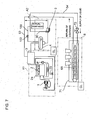
- FIG.3 is a schematic representation of the refrigerating apparatus of forced CO 2 circulation type in which CO 2 brine which has cooled a refrigeration load with its latent heat of vaporization is returned to be cooled through the heat exchange with ammonia refrigerant.
- reference symbol A is a machine unit (CO 2 brine producing apparatus) integrating an ammonia refrigerating cycle part (brine cooler 3) and an ammonia/CO 2 heat exchanging part (brine cooler 3), and B is a freezer unit for cooling(refrigerating) a refrigeration load by utilizing the latent heat of vaporization of CO 2 cooled in the machine unit side.
- B is a freezer unit for cooling(refrigerating) a refrigeration load by utilizing the latent heat of vaporization of CO 2 cooled in the machine unit side.
- reference numeral 1 is a compressor, the ammonia gas compressed by the compressor 1 is condensed in an evaporation type condenser 2, and the condensed liquid ammonia is expanded at an expansion valve 23 to be introduced into a CO 2 brine cooler 3 through a line 24.
- the ammonia evaporates in the brine cooler 3 while exchanging heat with CO 2 and introduced to the compressor 1 again to complete an ammonia cycle.
- Reference numeral 8 is a supercooler connected to a bypass pipe bypassing the line 24 between the outlet side of the expansion valve 23 and the inlet side of the brine cooler 3, the supercoller 8 being integrated in a CO 2 liquid receiver 4.
- the riser pipe 90 is provided to the outlet of the liquid pump 5.
- CO 2 brine is introduced to the brine cooler 3 for cooling the CO 2 brine
- CO 2 is cooled to be condensed through heat exchange with ammonia refrigerant
- the condensed liquid CO 2 is introduced to the liquid receiver 4 to be cooled by the supercooler 8 to a temperature lower than its saturation temperature in the liquid receiver 4 by 1 ⁇ 5 degrees C.
- the supercooled liquid CO 2 is introduced to the freezer unit B side by means of a liquid pump 5 provided in a CO 2 feed line 52 and driven by an inverter motor 51 of variable rotation speed.
- the top part of the riser pipe 90 is communicated to the CO 2 gas layer in the upper part in the liquid receiver 4 via the communication pipe 100.
- CO 2 brine liquid returned to the liquid receiver 4 is controlled by the size of the diameter of the communication pipe 100 or by the flow control valve 102 so that a part of the CO 2 brine liquid supplied by the liquid pump 5 and a large part thereof is supplied to the cooler 6.
- the CO 2 gas residing in the upper part in the liquid receiver 4 is supplied to the top part of the riser pipe 90.
- Reference numeral 9 is a bypass passage connecting the outlet side of the liquid pump 5 and the CO 2 brine cooler 3, and 11 is an ammonia detoxifying line, which connects to a detoxification nozzle 91 from which liquid CO 2 or liquid/gas mixed CO 2 from the CO 2 brine cooler 3 is sprayed to spaces where ammonia may leak such as near the compressor 1 by way of open/close valve 911.
- Reference numeral 12 is a neutralization line through which CO 2 is introduced from the CO 2 brine cooler 3 to the detoxifying water tank 7 to neutralize ammonia to ammonium carbonate.
- Reference numeral 13 is a fire extinguishing line.
- a valve 131 opens to allow CO 2 to be sprayed to extinguish the fire, the valve 131 being composed to be a safety valve which opens upon detecting a temperature rise or upon detecting an abnormal pressure rise of CO 2 in the brine cooler 3.
- Reference numeral 14 is a CO 2 relief line.
- a valve 151 When temperature rises in the unit A, a valve 151 is opened and CO 2 in the CO 2 brine cooler 3 is allowed to be released into the space inside the unit through an injection line 15 surrounding the liquid receiver 4 to cool the space.
- the valve 151 is composed as a safety valve which opens when the pressure in the brine cooler rises above a predetermined pressure during operation under load.
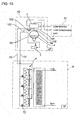
- a plurality of CO 2 brine coolers 6 are located above a conveyor 25 for transferring foodstuffs 27 to be frozen along the transfer direction of the conveyor.
- Liquid CO 2 introduced through the heat insulated joint 10 is partially evaporated in the coolers 6, air brown toward the foodstuffs 27 by means of cooler fans 29 is cooled by the coolers 6 on its way to the foodstuffs.
- the cooler fans 29 are arranged along the conveyor 25 and driven by inverter motors. 261 so that the rotation speed can be controlled.
- Defrosting spray nozzles 28 communicating to a defrost heat source are provided between the cooler fans 29 and the coolers 6.
- a relief line 30 provided with a safety valve or pressure regulation valve 31 is provided between the coolers 6 capable of allowing evaporation in a liquid or liquid/gas mixed state and the brine cooler 3 or the liquid receiver 4 provided in the downstream of the brine cooler in order to prevent undesired pressure rise due to gasified CO 2 and pressure rise on start up in addition to a recovery line for connecting the outlet side of each of the coolers 6 and the brine cooler 3.
- T 1 is a temperature sensor for detecting the temperature of liquid CO 2 in the liquid receiver 4
- T 2 is a temperature sensor for detecting the temperature of CO 2 at the inlet side of the freezer unit B
- T 3 is a temperature sensor for detecting the temperature of CO 2 at the outlet side of the freezer unit B
- T 4 is a temperature sensor for detecting the temperature of the space in the freezer unit B
- P 1 is a pressure sensor for detecting the pressure in the liquid receiver 4
- P 2 is a pressure sensor for detecting the pressure in the coolers 6
- P 3 is a pressure sensor for detecting the pressure difference between the outlet and inlet of the liquid pump 5
- CL is a controller for controlling the inverter motor 51 for driving the liquid pump 5 and the inverter motors 261 for driving the cooler fans 29.
- Reference numeral 20 is a open/close control valve of a bypass pipe 81 for supplying ammonia to the supercooler 8
- 21 is a open/close
- the embodiment example is composed such that the controller CL is provided for determining the degree of supercool by comparing saturation temperature and detected temperature of the liquid CO 2 based on the signals from the sensor T 1 and P 1 and the amount of ammonia refrigerant introduced to the bypass pipe 8 can be adjusted.
- the temperature of CO 2 in the liquid receiver 4 can be controlled to be lower than saturation temperature by 1 ⁇ 5 °C.
- the supercooler 8 may be provided outside the liquid receiver 4 independently not necessarily inside the liquid receiver 4.
- the signal from the sensor P 2 detecting the pressure in the coolers 6 capable of allowing evaporation in a liquid or liquid/gas mixed state(imperfectly evaporated state) is inputted to the controller CL which controls the inverter motors 51 to adjust the discharge of the liquid pump 5 (the adjustment including stepless adjustment of discharge and intermittent discharging), and stable supply of CO 2 to the coolers 6 can be performed through controlling the inverter 51.
- controller CL controls also the inverter motor 261 based on the signal from the sensor P 2 , and the rotation speed of the cooler fan 29 is controlled together with that of the liquid pump 5 so that CO 2 liquid flow and cooling air flow are controlled adequately.
- liquid CO 2 is circulated forcibly by means of the liquid pump 5 of variable discharge(with inverter motor) having discharge capacity of 3 - 4 times the flow necessary for the refrigeration load side, distribution of fluid CO 2 to the coolers 6 can be done well even in the case a plurality of coolers are provided.
- the controller CL allows the open/close control valve 21 on the bypass passage 9 to open, and CO 2 is bypassed to the brine cooler 3 for cooling CO 2 brine, as a result the gas of the gas/fluid mixed state of CO 2 in a cavitating state can be liquefied.
- Said controlling can be done in the ammonia cycle in such a way that, when the degree of supercool decreases when starting or refrigeration load varies and pressure difference between the outlet and inlet of the pump 5 decreases and cavitating state occurs, the pressure sensor P 3 detects that pressure difference between the outlet and inlet of the liquid pump 5 has decreased, the controller CL controls a control valve to unload the compressor 1 (displacement type compressor) to allow apparent saturation temperature of CO 2 to rise to secure the degree of supercool.
- the compressor 1 displacement type compressor
- the compressor 1 in the ammonia cycle side is operated to cool liquid CO 2 in the brine cooler 3 and the liquid receiver 4.
- the liquid pump 5 is operated intermittently /cyclically.
- the liquid pump 5 is operated at 0% ⁇ 100% ⁇ 60% ⁇ 0% ⁇ 100% ⁇ 60% rotation speed.
- 100% rotation speed means that the pump is driven by the inverter motor with the frequency of power source itself, and 0% means that the operation of the pump is halted.
- the pump is operated under 100%, when the pressure difference between the outlet and inlet of the pump reaches the value of full load operation (full load pump head), lowered to 60%, then operation of the liquid pump is halted for a predetermined period of time, after this again operated under 100%, when the pressure difference between the outlet and inlet of the pump reaches the value of full load operation (full load pump head), lowered to 60%, then shifted to normal operation while increasing inverter frequency to increase the rotation speed of the pump.
- CO2 in the freezer unit B When sanitizing the freezer unit after freezing operation is over, CO2 in the freezer unit B must be recovered to the liquid receiver 4 by way of the brine cooler 3 of the machine unit.
- the recovery operation can be controlled by detecting the temperature of liquid CO 2 at the inlet side and that of gaseous CO 2 at the outlet side of the coolers 6 by the temperature sensor T 2 , T 3 respectively, grasping by the controller CL the temperature difference between the temperatures detected by T 2 and T 3 , and judging the remaining amount of CO 2 in the freezer unit B. That is, it is judged that recovery is completed when the temperature difference becomes zero.
- the recovery operation can be controlled also by detecting the temperature of the space in the freezer unit and the pressure of CO 2 at the outlet side of the cooler 3 by the temperature sensor T 4 and pressure sensor P 3 respectively, comparing the space temperature detected by the sensor T 4 with saturation temperature of CO 2 at the pressure detected by the sensor P 3 , and judging on the basis of the difference between the saturation temperature and the detected space temperature whether CO 2 remains in the freezer unit B or not.
- coolers 6 are of sprinkled water defrosting type
- time needed for CO 2 recovery can be shortened by utilizing the heat of sprinkled water.
- it is suitable to perform defrost control in which the amount of sprinkling water is controlled while monitoring the pressure of CO 2 at the outlet side of the coolers 6 detected by the sensor P 2 .
- the connecting parts of CO 2 lines of the machine unit A to those of the freezer unit B are used heat insulatedjoint made of low heat conduction material such as reinforced glass, etc. so that the heat is not conducted to the CO 2 lines of the machine unit A through the connecting parts.
- This embodiment consists of an evaporation type condenser unit A1 for NH 3 , a machine unit A2, and an ice-making room B. All of the units are installed on the ground level(on the earth) and there is no difference between them in height level from the earth.
- GL means that all of the unit A1, unit A2, and room B are installed on the ground level.
- the NH 3 evaporation type condenser unit A1 is an ammonia refrigerating machine comprising an ammonia compressor 1, an evaporating type condenser 2, an expansion valve 23, and a brine cooler 3, being located at high position near the ceiling of the evaporating type condenser unit A.
- Ammonia gas compressed by the compressor is cooled in the evaporation type condenser 2 which is cooled by sprinkled water and air blown by a cooling fan 2a, the condensed liquid ammonia is expanded at the expansion valve 23 to be introduced into the brine cooler 3 where CO 2 brine is cooled by the latent heat of vaporization of the ammonia introduced thereinto.
- the machine unit A2 is located adjacent to the evaporation type condenser unit A1 on the same ground level but it is formed to have a ceiling positioned a little lower than that of the evaporation type condenser unit A1.
- the machine unit contains a liquid receiver 4 for receiving the liquid ammonia cooled and condensed in the brine cooler 3 contained in the evaporation type condenser unit A1, a brine pump 5 of variable rotation speed, and a riser pipe 90.
- the riser pipe 90 is formed such that its top part runs in a position higher than the liquid level in the liquid receiver 4 and level with or a little lower than the top part of a return pipe 53 for returning CO 2 from the ice-making room B to the brine cooler 3, the top part of the return pipe 53 running in a position level with or a little higher than the top of the brine cooler 3.
- the level of the top part of the riser pipe 90 is higher than the maximum liquid level in the brine cooler 3.
- the top part of the riser pipe 90 runs in the duct under the roof in which the top part of the return pipe 53 runs, the return pipe 53 being designed in consideration of actual discharge head of the brine pump 5 and pressure loss in the return pipe.
- the volume of the liquid receiver 4 including the volume in the pipe connecting to the inlet of the liquid pump 5 is determined so that there remains a room for CO 2 gas in the upper part in the liquid receiver 4 in addition to the liquid CO 2 in the brine cycle when the operation of CO 2 brine cycle is halted.
- the brine pump 5 is a liquid pump for allowing forced circulation of CO 2 and its discharge capacity is determined at least equal to or larger than 2 times the circulation flow required by the cooler side so that CO 2 is recovered from the outlet of the cooler in the refrigeration load side in a state of liquid or in a substantially liquid state although mixed with gaseous CO 2 .
- the brine pump 5 is driven to achieve a discharge head to overcome the liquid CO 2 head in the piping and pressure loss in the piping, and is located so that enough suction pressure is secured.
- the pressure in the suction side of the pump 5 must be above saturation pressure even when the pump is operating at maximum discharge, and it is necessary that the liquid receiver 4 containing supercooled CO 2 is located at a position at least higher than the suction side of the pump.
- the ice-making room B is distant from the machine unit A2 and the evaporation type condenser unit A1, they are installed on the same ground level.
- a calcium chloride brine tank 71 in which a herringbone coil 6A(evaporator) for CO 2 brine is accommodated. Liquid CO 2 is supplied to the coil 6A(evaporator) through the riser pipe 90 and a liquid valve 72.
- the liquid CO 2 evaporates in the coil 6A and cools the calcium chloride brine in the tank 71 with the latent heat of vaporization thereof and returns in a gas/liquid mixed state to the brine cooler 3 of the evaporation type condenser unit A1 through the return pipe 53 running in the duct 73 under the roof located at a position higher than the brine cooler 3.
- ammonia gas compressed by the compressor 1 is condensed in the evaporation type condenser 2, the condensed liquid ammonia is expanded at the expansion valve to be introduced into the brine cooler 3 where the ammonia is evaporated while exchanging heat with CO 2 , then the evaporated ammonia is again introduced to the compressor to complete an ammonia refrigerating cycle.
- the supercooled liquid CO 2 can easily be fed under pressure by the brine pump 5 against the actual net liquid head to the top of the riser pipe 90.
- the supercooled liquid CO 2 is introduced to the cooler(herringbone coil)6A of the, ice-making room by the hydraulic head(supply process of liquid CO 2 from the brine cooler 3 to the cooler 6A).
- Calcium chloride brine is cooled in the cooler 6A by the latent heat of vaporization of the liquid CO 2 .
- the discharge of the brine pump 5 is determined to be at least 2 times or larger than the circulation flow required by the cooler 6A side, it does not occur that all of the CO 2 brine evaporates in the cooler 6A even under full load of refrigeration, and CO 2 brine can be returned to the brine cooler 3 in a liquid state or liquid/gas mixed state through the return piping 53 of which the top part runs in a duct provided in a position higher than the brine cooler 3 under the roof.
- the diameters of the riser pipe 90 and the return pipe 53 can be made small and the pipes can be provided to run in the duct located under roof in a positioned higher than the brine cooler 3 with the cooler 6A being located on the ground. Therefore, it is not necessary that piping runs extending around the cooler 6A and
- Fig.8 represents the third embodiment of the present invention.
- the embodiment relates to a refrigeration storehouse.
- the (NH 3 ) evaporation type condenser unit and the receiver unit of FIG.12 are unitized as an outdoor unit A, and a hanger type air chiller 6B of CO 2 brine type is provided in a refrigeration storehouse B.
- a riser pipe 90 is provided to connect a brine pump 5 located in the outdoor unit A to the air chiller 6B in the refrigeration storehouse B.
- Both the outdoor unit A and refrigeration warehouse B are installed on the ground level(on the earth).
- the outdoor unit A contains an ammonia compressor 1, evaporation type condenser 2, an expansion valve 23, and a brine cooler 3 to perform an ammonia refrigerating cycle, and a liquid receiver 4 and a brine liquid pump 5 is provided below the brine cooler 3.
- the discharge port of the pump 5 is connected to the air chiller 6B in the refrigeration storehouse B by means of a riser pipe 90.
- the air chiller 6B is located near the ceiling of the refrigeration storehouse B at a position higher than the brine cooler, and the top part of the riser pipe 90 runs along a height position the same or higher than the return pipe for returning the CO 2 brine from the air chiller 6B to the brine cooler 3.
- the configuration of the embodiment is similar to that of the embodiment of FIG. 12 other than the above-mentioned point, but in this embodiment, the air chiller 6B is a hanger type air chiller of CO 2 brine type hanging from the ceiling and located in a higher position than the brine cooler.
- the system according to the invention can be applied even in the case the air chiller 6B is located at a higher than the brine cooler 3 like this without problems.
- GL means that the unit A and B are on the ground level.
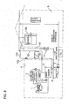
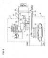
- FIG.9 represents the fourth embodiment of the present invention.
- the (NH 3 ) evaporation type condenser unit and the receiver unit of FIG. 12 are unitized as an outdoor unit A and located on the ceiling of a freezing store B containing a CO 2 brine type freezer(freezer type chiller) in a refrigerating factory.
- a brine pump 5 located in the outdoor unit A is connected to the air chiller 6C by means of a riser pipe 90.
- the top part of the riser pipe 90 runs along a height position higher than the brine cooler 3 mounting position and about the same height level with a return pipe 53 for returning CO 2 brine from the cooler 6C to the brine cooler 3.
- the configuration of the embodiment is similar to that of other embodiments other than the above-mentioned point, but in this embodiment, the freezer type chiller 6B in the freezing store B is located at a position lower than the brine cooler in the outdoor unit A which is located on the ceiling of the of the freezer store B. Both the top part of the riser pipe 90 and return pipe 53 is located to run along a height position higher than the maximum liquid level of CO 2 in the liquid receiver 4, preferably higher than the brine cooler 3.
- ceiling and GL means respectively the level of the ceiling and the ground level.
- the example 5 shown in FIG.10 is a case the cooler 6 is located in the first floor and an evaporation type condenser unit A1 and machine unit A2 are located in a machine room provided in the fourth floor.
- the (NH 3 ) evaporation type condenser unit A1 comprises an ammonia compressor, an evaporator condenser, an expansion valve not sown in the drawing, and the brine cooler 3 is provided in the machine unit A2, thus an ammonia refrigerating cycle is composed.
- the machine unit A2 is located adjacent the evaporation type condenser unit A1.
- the machine unit A2 comprises the liquid receiver 4 for receiving CO 2 cooled and liquefied in the brine cooler 3, the variable speed liquid pump 5, and the riser pipe 90.
- the top part of the riser pipe 90 is positioned in a height position higher than that of the liquid receiver 4.
- the top part is communicated to the CO 2 gas layer 4a in the liquid receiver 4 via the communication pipe 100, and the flow control valve 102 is attached to the communication pipe 100.
- CO 2 brine liquid flows under discharge pressure of the liquid pump 5 located below the liquid receiver 4 through a liquid supply piping 54 and via each of valves 72 into each of coolers 6. A part of CO 2 brine liquid evaporates in the coolers 6, and CO 2 of gas/liquid mixed state returns to the liquid receiver 4 via a return pipe 53.
- the brine cooler 3 is located at a height position higher than that of the liquid receiver 4, and CO 2 recovered from the outlets of the coolers 6 is returned to the CO 2 gas layer 4a in the liquid receiver 4 not to the brine cooler.
- the CO 2 gas layer 4a in the liquid receiver 4 is communicated to the brine cooler 3 via a pipe 104 so that condensed and liquefied CO 2 brine is stored in the liquid receiver 4.
- a condensing cycle can be carried out by communicating the CO 2 gas layer 4a in the liquid receiver 4 to brine cooler 3 via the piping 104 to condense and liquefy the CO 2 of the CO 2 gas layer 4a in the liquid receiver 4, and returning the liquefied CO 2 to the liquid receiver 4 via a pipe 106 to be stored in the liquid receiver 4, so condensation and liquefaction of CO 2 can be carried out also in a case of not returning the liquid CO 2 to the brine cooler 3.
- an ammonia refrigerating cycle, a brine cooler to cool and liquefy the CO 2 by utilizing the latent heat of vaporization of the ammonia, and a CO 2 brine producing apparatus having a liquid pump in the CO 2 supply line for supplying CO 2 to the refrigeration load side are unitized in a single unit, and the ammonia cycle and CO 2 brine cycle can be combined without problems even when refrigeration load such as refrigerating showcase, etc. is located in any place in accordance with circumstances of customer's convenience.
- CO 2 circulation cycle can be formed irrespective of the position of the CO 2 cycle side cooler, kind thereof (bottom feed type of top feed type), and the number thereof, and further even when the brine cooler is located at a position lower than the refrigeration load side cooler.
Landscapes
- Engineering & Computer Science (AREA)
- Physics & Mathematics (AREA)
- Mechanical Engineering (AREA)
- Thermal Sciences (AREA)
- General Engineering & Computer Science (AREA)
- Carbon And Carbon Compounds (AREA)
- Devices That Are Associated With Refrigeration Equipment (AREA)
- Sorption Type Refrigeration Machines (AREA)
Applications Claiming Priority (2)
| Application Number | Priority Date | Filing Date | Title |
|---|---|---|---|
| JP2004289105A JP2005172416A (ja) | 2003-11-21 | 2004-09-30 | アンモニア/co2冷凍システム |
| PCT/JP2005/012232 WO2006038354A1 (ja) | 2004-09-30 | 2005-07-01 | アンモニア/co2冷凍システム |
Publications (3)
| Publication Number | Publication Date |
|---|---|
| EP1795831A1 EP1795831A1 (en) | 2007-06-13 |
| EP1795831A4 EP1795831A4 (en) | 2010-09-01 |
| EP1795831B1 true EP1795831B1 (en) | 2014-02-12 |
Family
ID=36142439
Family Applications (1)
| Application Number | Title | Priority Date | Filing Date |
|---|---|---|---|
| EP05765291.9A Expired - Lifetime EP1795831B1 (en) | 2004-09-30 | 2005-07-01 | Ammonia/co2 refrigeration system |
Country Status (9)
| Country | Link |
|---|---|
| US (1) | US7406837B2 (enExample) |
| EP (1) | EP1795831B1 (enExample) |
| JP (1) | JP4465686B2 (enExample) |
| KR (1) | KR100858991B1 (enExample) |
| CN (1) | CN100588888C (enExample) |
| CA (1) | CA2602536C (enExample) |
| ES (1) | ES2459990T3 (enExample) |
| TW (1) | TW200619572A (enExample) |
| WO (1) | WO2006038354A1 (enExample) |
Families Citing this family (35)
| Publication number | Priority date | Publication date | Assignee | Title |
|---|---|---|---|---|
| JP2007071519A (ja) * | 2005-09-09 | 2007-03-22 | Sanden Corp | 冷却システム |
| JP2007315694A (ja) * | 2006-05-26 | 2007-12-06 | Mayekawa Mfg Co Ltd | デシカント空調システム及びその運転方法 |
| JP4734611B2 (ja) * | 2006-12-20 | 2011-07-27 | 株式会社前川製作所 | 空調設備のリニューアルユニット及びそれを用いた空調設備の施工方法 |
| DE102007024842A1 (de) * | 2007-05-29 | 2008-12-04 | Fraunhofer-Gesellschaft zur Förderung der angewandten Forschung e.V. | Kryoeinrichtung und zugehöriges Betriebsverfahren zum aktiven Brandschutz |
| CA2662986C (en) * | 2008-04-18 | 2012-02-07 | Serge Dube | Co2 refrigeration unit |
| US9989280B2 (en) * | 2008-05-02 | 2018-06-05 | Heatcraft Refrigeration Products Llc | Cascade cooling system with intercycle cooling or additional vapor condensation cycle |
| EP2320158B1 (en) * | 2008-07-28 | 2017-11-15 | Mayekawa Mfg. Co., Ltd. | Heat pump system |
| US9238398B2 (en) * | 2008-09-25 | 2016-01-19 | B/E Aerospace, Inc. | Refrigeration systems and methods for connection with a vehicle's liquid cooling system |
| US20100140286A1 (en) * | 2008-12-08 | 2010-06-10 | Michael Christopher Quinn | Portable beverage machine |
| JP5512339B2 (ja) * | 2010-03-17 | 2014-06-04 | 株式会社前川製作所 | 既設食品冷凍設備の改造方法 |
| JP5662112B2 (ja) * | 2010-11-11 | 2015-01-28 | 株式会社前川製作所 | 凍結冷蔵方法及び凍結冷蔵設備 |
| US9664424B2 (en) * | 2010-11-17 | 2017-05-30 | Hill Phoenix, Inc. | Cascade refrigeration system with modular ammonia chiller units |
| US9657977B2 (en) | 2010-11-17 | 2017-05-23 | Hill Phoenix, Inc. | Cascade refrigeration system with modular ammonia chiller units |
| WO2012098581A1 (ja) * | 2011-01-20 | 2012-07-26 | 三菱電機株式会社 | 空気調和装置 |
| CA2838743C (en) | 2011-06-13 | 2020-03-24 | Fred LINGELBACH | Condenser evaporator system (ces) for a refrigeration system and method |
| CA2838730C (en) | 2011-06-13 | 2019-08-06 | Fred LINGELBACH | Refrigeration system and methods for refrigeration |
| EP2562491B1 (en) * | 2011-08-24 | 2019-05-01 | Mahle International GmbH | Filling system for transferring refrigerant to a refrigeration system and method of operating a filling system |
| WO2013145027A1 (ja) * | 2012-03-30 | 2013-10-03 | 三菱電機株式会社 | 冷凍装置及び冷凍サイクル装置 |
| KR101760694B1 (ko) | 2013-02-12 | 2017-07-24 | 하치요엔지니아린구 가부시키가이샤 | 데이터 센터의 냉각기구 |
| ES2988494T3 (es) * | 2013-05-03 | 2024-11-20 | Hill Phoenix Inc | Sistemas y métodos para el control de presión en un sistema de refrigeración por CO2 |
| US20150068037A1 (en) * | 2013-09-06 | 2015-03-12 | Spx Corporation | Thermal System Including an Environmental Test Chamber |
| WO2015057299A1 (en) * | 2013-10-17 | 2015-04-23 | Carrier Corporation | Two-phase refrigeration system |
| KR101790461B1 (ko) | 2013-12-17 | 2017-10-25 | 가부시끼가이샤 마에가와 세이사꾸쇼 | 냉동 장치의 승화 디프로스트 시스템 및 승화 디프로스트 방법 |
| CN107636402A (zh) * | 2015-05-13 | 2018-01-26 | 开利公司 | 喷射器制冷回路 |
| JP2017036886A (ja) * | 2015-08-10 | 2017-02-16 | 八洋エンジニアリング株式会社 | アンモニア冷凍装置 |
| US11125483B2 (en) | 2016-06-21 | 2021-09-21 | Hill Phoenix, Inc. | Refrigeration system with condenser temperature differential setpoint control |
| CN107879359A (zh) * | 2017-12-11 | 2018-04-06 | 营口萌达电子科技有限公司 | 一种液氨蒸发器撬装设备 |
| US11378318B2 (en) | 2018-03-06 | 2022-07-05 | Vilter Manufacturing Llc | Cascade system for use in economizer compressor and related methods |
| US11796227B2 (en) | 2018-05-24 | 2023-10-24 | Hill Phoenix, Inc. | Refrigeration system with oil control system |
| US11397032B2 (en) | 2018-06-05 | 2022-07-26 | Hill Phoenix, Inc. | CO2 refrigeration system with magnetic refrigeration system cooling |
| US10663201B2 (en) | 2018-10-23 | 2020-05-26 | Hill Phoenix, Inc. | CO2 refrigeration system with supercritical subcooling control |
| CN109647093B (zh) * | 2019-01-31 | 2021-04-13 | 江苏师范大学 | 气体冷凝器、环保空气除尘装置 |
| EP3971493A4 (en) * | 2019-05-15 | 2023-01-11 | Mayekawa Mfg. Co., Ltd. | ICE MAKING MACHINE |
| KR20240171864A (ko) | 2023-05-31 | 2024-12-09 | 주식회사 한국마이콤 | 냉각 시스템 및 그 제어방법 |
| US12487017B2 (en) | 2023-06-02 | 2025-12-02 | Hill Phoenix, Inc. | CO2 refrigeration system with supercritical subcooling control |
Family Cites Families (11)
| Publication number | Priority date | Publication date | Assignee | Title |
|---|---|---|---|---|
| JPS5270473A (en) | 1975-12-10 | 1977-06-11 | Hitachi Ltd | Refrigerator |
| JP2902068B2 (ja) | 1990-07-18 | 1999-06-07 | 三機工業株式会社 | 空調用受液装置 |
| GB2258298B (en) * | 1991-07-31 | 1995-05-17 | Star Refrigeration | Cooling method and apparatus |
| US5442931A (en) * | 1994-08-02 | 1995-08-22 | Gas Research Institute | Simplified adsorption heat pump using passive heat recuperation |
| NO970066D0 (no) * | 1997-01-08 | 1997-01-08 | Norild As | Kuldeanlegg med lukket sirkulasjonskrets |
| JP3365273B2 (ja) * | 1997-09-25 | 2003-01-08 | 株式会社デンソー | 冷凍サイクル |
| US6619066B1 (en) | 1999-02-24 | 2003-09-16 | Hachiyo Engineering Co., Ltd. | Heat pump system of combination of ammonia cycle carbon dioxide cycle |
| JP2001091069A (ja) * | 1999-09-17 | 2001-04-06 | Hitachi Ltd | アンモニア冷凍装置 |
| DK174257B1 (da) * | 2001-02-23 | 2002-10-21 | Teknologisk Inst | Anlæg samt fremgangsmåde, hvor CO2 anvendes som kølemiddel og som arbejdsmedie ved afrimning |
| JP2003166765A (ja) * | 2001-11-30 | 2003-06-13 | Hachiyo Engneering Kk | アンモニアサイクルと炭酸ガスサイクルとを組み合わせた二元冷凍システム |
| US6966196B2 (en) * | 2003-12-30 | 2005-11-22 | Mayekawa Mfg. Co., Ltd. | Refrigeration unit using ammonia |
-
2005
- 2005-07-01 CA CA2602536A patent/CA2602536C/en not_active Expired - Lifetime
- 2005-07-01 EP EP05765291.9A patent/EP1795831B1/en not_active Expired - Lifetime
- 2005-07-01 JP JP2006539158A patent/JP4465686B2/ja not_active Expired - Lifetime
- 2005-07-01 WO PCT/JP2005/012232 patent/WO2006038354A1/ja not_active Ceased
- 2005-07-01 KR KR1020077007464A patent/KR100858991B1/ko not_active Expired - Lifetime
- 2005-07-01 CN CN200580033187A patent/CN100588888C/zh not_active Expired - Lifetime
- 2005-07-01 ES ES05765291.9T patent/ES2459990T3/es not_active Expired - Lifetime
- 2005-07-04 TW TW094122597A patent/TW200619572A/zh not_active IP Right Cessation
-
2007
- 2007-03-28 US US11/692,291 patent/US7406837B2/en not_active Expired - Lifetime
Also Published As
| Publication number | Publication date |
|---|---|
| JP4465686B2 (ja) | 2010-05-19 |
| JPWO2006038354A1 (ja) | 2008-05-15 |
| EP1795831A1 (en) | 2007-06-13 |
| CA2602536C (en) | 2012-09-18 |
| CN100588888C (zh) | 2010-02-10 |
| KR100858991B1 (ko) | 2008-09-18 |
| KR20070055579A (ko) | 2007-05-30 |
| EP1795831A4 (en) | 2010-09-01 |
| CA2602536A1 (en) | 2006-04-13 |
| CN101031761A (zh) | 2007-09-05 |
| ES2459990T3 (es) | 2014-05-13 |
| TWI345042B (enExample) | 2011-07-11 |
| US7406837B2 (en) | 2008-08-05 |
| US20070234753A1 (en) | 2007-10-11 |
| WO2006038354A1 (ja) | 2006-04-13 |
| TW200619572A (en) | 2006-06-16 |
Similar Documents
| Publication | Publication Date | Title |
|---|---|---|
| EP1795831B1 (en) | Ammonia/co2 refrigeration system | |
| EP1688685B1 (en) | Ammonia / CO2 refrigeration system | |
| JP2005172416A (ja) | アンモニア/co2冷凍システム | |
| EP2716998B1 (en) | Air conditioning device | |
| CN101124438B (zh) | 具有热回收的co2制冷设备 | |
| US5953934A (en) | Refrigerant circulating apparatus and method of assembling a refrigerant circuit | |
| EP1614980A2 (en) | Refrigeration system | |
| EP3179182B1 (en) | Refrigerator and method of controlling the same | |
| EP3158275B1 (en) | Refrigerator | |
| EP2869004B1 (en) | Refrigerator and method for controlling the same | |
| CA2748027C (en) | Cooling-heating device for ice rink facility | |
| CN100408942C (zh) | 空调冷冻装置及空调冷冻装置的控制方法 | |
| US20250102205A1 (en) | Air-conditioning apparatus | |
| KR102306451B1 (ko) | 냉동장치 | |
| KR20210007203A (ko) | 냉동장치 |
Legal Events
| Date | Code | Title | Description |
|---|---|---|---|
| PUAI | Public reference made under article 153(3) epc to a published international application that has entered the european phase |
Free format text: ORIGINAL CODE: 0009012 |
|
| 17P | Request for examination filed |
Effective date: 20070424 |
|
| AK | Designated contracting states |
Kind code of ref document: A1 Designated state(s): AT BE BG CH CY CZ DE DK EE ES FI FR GB GR HU IE IS IT LI LT LU LV MC NL PL PT RO SE SI SK TR |
|
| DAX | Request for extension of the european patent (deleted) | ||
| A4 | Supplementary search report drawn up and despatched |
Effective date: 20100729 |
|
| 17Q | First examination report despatched |
Effective date: 20100820 |
|
| GRAP | Despatch of communication of intention to grant a patent |
Free format text: ORIGINAL CODE: EPIDOSNIGR1 |
|
| INTG | Intention to grant announced |
Effective date: 20130809 |
|
| GRAS | Grant fee paid |
Free format text: ORIGINAL CODE: EPIDOSNIGR3 |
|
| GRAA | (expected) grant |
Free format text: ORIGINAL CODE: 0009210 |
|
| AK | Designated contracting states |
Kind code of ref document: B1 Designated state(s): AT BE BG CH CY CZ DE DK EE ES FI FR GB GR HU IE IS IT LI LT LU LV MC NL PL PT RO SE SI SK TR |
|
| REG | Reference to a national code |
Ref country code: GB Ref legal event code: FG4D |
|
| REG | Reference to a national code |
Ref country code: CH Ref legal event code: EP |
|
| REG | Reference to a national code |
Ref country code: AT Ref legal event code: REF Ref document number: 652319 Country of ref document: AT Kind code of ref document: T Effective date: 20140215 |
|
| REG | Reference to a national code |
Ref country code: DE Ref legal event code: R096 Ref document number: 602005042676 Country of ref document: DE Effective date: 20140320 |
|
| REG | Reference to a national code |
Ref country code: IE Ref legal event code: FG4D |
|
| REG | Reference to a national code |
Ref country code: ES Ref legal event code: FG2A Ref document number: 2459990 Country of ref document: ES Kind code of ref document: T3 Effective date: 20140513 |
|
| REG | Reference to a national code |
Ref country code: NL Ref legal event code: VDEP Effective date: 20140212 |
|
| REG | Reference to a national code |
Ref country code: AT Ref legal event code: MK05 Ref document number: 652319 Country of ref document: AT Kind code of ref document: T Effective date: 20140212 |
|
| REG | Reference to a national code |
Ref country code: LT Ref legal event code: MG4D |
|
| PG25 | Lapsed in a contracting state [announced via postgrant information from national office to epo] |
Ref country code: LT Free format text: LAPSE BECAUSE OF FAILURE TO SUBMIT A TRANSLATION OF THE DESCRIPTION OR TO PAY THE FEE WITHIN THE PRESCRIBED TIME-LIMIT Effective date: 20140212 Ref country code: IS Free format text: LAPSE BECAUSE OF FAILURE TO SUBMIT A TRANSLATION OF THE DESCRIPTION OR TO PAY THE FEE WITHIN THE PRESCRIBED TIME-LIMIT Effective date: 20140612 |
|
| PG25 | Lapsed in a contracting state [announced via postgrant information from national office to epo] |
Ref country code: SE Free format text: LAPSE BECAUSE OF FAILURE TO SUBMIT A TRANSLATION OF THE DESCRIPTION OR TO PAY THE FEE WITHIN THE PRESCRIBED TIME-LIMIT Effective date: 20140212 Ref country code: AT Free format text: LAPSE BECAUSE OF FAILURE TO SUBMIT A TRANSLATION OF THE DESCRIPTION OR TO PAY THE FEE WITHIN THE PRESCRIBED TIME-LIMIT Effective date: 20140212 Ref country code: NL Free format text: LAPSE BECAUSE OF FAILURE TO SUBMIT A TRANSLATION OF THE DESCRIPTION OR TO PAY THE FEE WITHIN THE PRESCRIBED TIME-LIMIT Effective date: 20140212 Ref country code: FI Free format text: LAPSE BECAUSE OF FAILURE TO SUBMIT A TRANSLATION OF THE DESCRIPTION OR TO PAY THE FEE WITHIN THE PRESCRIBED TIME-LIMIT Effective date: 20140212 Ref country code: PT Free format text: LAPSE BECAUSE OF FAILURE TO SUBMIT A TRANSLATION OF THE DESCRIPTION OR TO PAY THE FEE WITHIN THE PRESCRIBED TIME-LIMIT Effective date: 20140612 Ref country code: CY Free format text: LAPSE BECAUSE OF FAILURE TO SUBMIT A TRANSLATION OF THE DESCRIPTION OR TO PAY THE FEE WITHIN THE PRESCRIBED TIME-LIMIT Effective date: 20140212 |
|
| PG25 | Lapsed in a contracting state [announced via postgrant information from national office to epo] |
Ref country code: LV Free format text: LAPSE BECAUSE OF FAILURE TO SUBMIT A TRANSLATION OF THE DESCRIPTION OR TO PAY THE FEE WITHIN THE PRESCRIBED TIME-LIMIT Effective date: 20140212 |
|
| PG25 | Lapsed in a contracting state [announced via postgrant information from national office to epo] |
Ref country code: RO Free format text: LAPSE BECAUSE OF FAILURE TO SUBMIT A TRANSLATION OF THE DESCRIPTION OR TO PAY THE FEE WITHIN THE PRESCRIBED TIME-LIMIT Effective date: 20140212 Ref country code: EE Free format text: LAPSE BECAUSE OF FAILURE TO SUBMIT A TRANSLATION OF THE DESCRIPTION OR TO PAY THE FEE WITHIN THE PRESCRIBED TIME-LIMIT Effective date: 20140212 Ref country code: DK Free format text: LAPSE BECAUSE OF FAILURE TO SUBMIT A TRANSLATION OF THE DESCRIPTION OR TO PAY THE FEE WITHIN THE PRESCRIBED TIME-LIMIT Effective date: 20140212 Ref country code: CZ Free format text: LAPSE BECAUSE OF FAILURE TO SUBMIT A TRANSLATION OF THE DESCRIPTION OR TO PAY THE FEE WITHIN THE PRESCRIBED TIME-LIMIT Effective date: 20140212 |
|
| REG | Reference to a national code |
Ref country code: DE Ref legal event code: R097 Ref document number: 602005042676 Country of ref document: DE |
|
| PG25 | Lapsed in a contracting state [announced via postgrant information from national office to epo] |
Ref country code: PL Free format text: LAPSE BECAUSE OF FAILURE TO SUBMIT A TRANSLATION OF THE DESCRIPTION OR TO PAY THE FEE WITHIN THE PRESCRIBED TIME-LIMIT Effective date: 20140212 Ref country code: SK Free format text: LAPSE BECAUSE OF FAILURE TO SUBMIT A TRANSLATION OF THE DESCRIPTION OR TO PAY THE FEE WITHIN THE PRESCRIBED TIME-LIMIT Effective date: 20140212 |
|
| PLBE | No opposition filed within time limit |
Free format text: ORIGINAL CODE: 0009261 |
|
| STAA | Information on the status of an ep patent application or granted ep patent |
Free format text: STATUS: NO OPPOSITION FILED WITHIN TIME LIMIT |
|
| 26N | No opposition filed |
Effective date: 20141113 |
|
| REG | Reference to a national code |
Ref country code: DE Ref legal event code: R097 Ref document number: 602005042676 Country of ref document: DE Effective date: 20141113 |
|
| PG25 | Lapsed in a contracting state [announced via postgrant information from national office to epo] |
Ref country code: LU Free format text: LAPSE BECAUSE OF FAILURE TO SUBMIT A TRANSLATION OF THE DESCRIPTION OR TO PAY THE FEE WITHIN THE PRESCRIBED TIME-LIMIT Effective date: 20140701 |
|
| REG | Reference to a national code |
Ref country code: CH Ref legal event code: PL |
|
| PG25 | Lapsed in a contracting state [announced via postgrant information from national office to epo] |
Ref country code: IT Free format text: LAPSE BECAUSE OF FAILURE TO SUBMIT A TRANSLATION OF THE DESCRIPTION OR TO PAY THE FEE WITHIN THE PRESCRIBED TIME-LIMIT Effective date: 20140212 |
|
| REG | Reference to a national code |
Ref country code: IE Ref legal event code: MM4A |
|
| PG25 | Lapsed in a contracting state [announced via postgrant information from national office to epo] |
Ref country code: LI Free format text: LAPSE BECAUSE OF NON-PAYMENT OF DUE FEES Effective date: 20140731 Ref country code: CH Free format text: LAPSE BECAUSE OF NON-PAYMENT OF DUE FEES Effective date: 20140731 |
|
| PG25 | Lapsed in a contracting state [announced via postgrant information from national office to epo] |
Ref country code: SI Free format text: LAPSE BECAUSE OF FAILURE TO SUBMIT A TRANSLATION OF THE DESCRIPTION OR TO PAY THE FEE WITHIN THE PRESCRIBED TIME-LIMIT Effective date: 20140212 |
|
| PG25 | Lapsed in a contracting state [announced via postgrant information from national office to epo] |
Ref country code: IE Free format text: LAPSE BECAUSE OF NON-PAYMENT OF DUE FEES Effective date: 20140701 |
|
| PG25 | Lapsed in a contracting state [announced via postgrant information from national office to epo] |
Ref country code: MC Free format text: LAPSE BECAUSE OF FAILURE TO SUBMIT A TRANSLATION OF THE DESCRIPTION OR TO PAY THE FEE WITHIN THE PRESCRIBED TIME-LIMIT Effective date: 20140212 |
|
| PG25 | Lapsed in a contracting state [announced via postgrant information from national office to epo] |
Ref country code: BG Free format text: LAPSE BECAUSE OF FAILURE TO SUBMIT A TRANSLATION OF THE DESCRIPTION OR TO PAY THE FEE WITHIN THE PRESCRIBED TIME-LIMIT Effective date: 20140212 |
|
| PG25 | Lapsed in a contracting state [announced via postgrant information from national office to epo] |
Ref country code: GR Free format text: LAPSE BECAUSE OF FAILURE TO SUBMIT A TRANSLATION OF THE DESCRIPTION OR TO PAY THE FEE WITHIN THE PRESCRIBED TIME-LIMIT Effective date: 20140513 |
|
| REG | Reference to a national code |
Ref country code: FR Ref legal event code: PLFP Year of fee payment: 12 |
|
| PG25 | Lapsed in a contracting state [announced via postgrant information from national office to epo] |
Ref country code: HU Free format text: LAPSE BECAUSE OF FAILURE TO SUBMIT A TRANSLATION OF THE DESCRIPTION OR TO PAY THE FEE WITHIN THE PRESCRIBED TIME-LIMIT; INVALID AB INITIO Effective date: 20050701 |
|
| REG | Reference to a national code |
Ref country code: FR Ref legal event code: PLFP Year of fee payment: 13 |
|
| REG | Reference to a national code |
Ref country code: FR Ref legal event code: PLFP Year of fee payment: 14 |
|
| PGFP | Annual fee paid to national office [announced via postgrant information from national office to epo] |
Ref country code: GB Payment date: 20240530 Year of fee payment: 20 |
|
| PGFP | Annual fee paid to national office [announced via postgrant information from national office to epo] |
Ref country code: FR Payment date: 20240611 Year of fee payment: 20 |
|
| PGFP | Annual fee paid to national office [announced via postgrant information from national office to epo] |
Ref country code: TR Payment date: 20240630 Year of fee payment: 20 Ref country code: BE Payment date: 20240614 Year of fee payment: 20 |
|
| PGFP | Annual fee paid to national office [announced via postgrant information from national office to epo] |
Ref country code: DE Payment date: 20240529 Year of fee payment: 20 |
|
| PGFP | Annual fee paid to national office [announced via postgrant information from national office to epo] |
Ref country code: ES Payment date: 20240801 Year of fee payment: 20 |
|
| REG | Reference to a national code |
Ref country code: DE Ref legal event code: R071 Ref document number: 602005042676 Country of ref document: DE |
|
| PG25 | Lapsed in a contracting state [announced via postgrant information from national office to epo] |
Ref country code: GB Free format text: LAPSE BECAUSE OF EXPIRATION OF PROTECTION Effective date: 20250630 |
|
| REG | Reference to a national code |
Ref country code: GB Ref legal event code: PE20 Expiry date: 20250630 |
|
| REG | Reference to a national code |
Ref country code: ES Ref legal event code: FD2A Effective date: 20250729 |
|
| REG | Reference to a national code |
Ref country code: BE Ref legal event code: MK Effective date: 20250701 |
|
| PG25 | Lapsed in a contracting state [announced via postgrant information from national office to epo] |
Ref country code: ES Free format text: LAPSE BECAUSE OF EXPIRATION OF PROTECTION Effective date: 20250702 |