EP1795817A2 - Installation for supplying heat with at least two separated circuits, working at different temperature, with at least one heat source and method for operating the same - Google Patents
Installation for supplying heat with at least two separated circuits, working at different temperature, with at least one heat source and method for operating the same Download PDFInfo
- Publication number
- EP1795817A2 EP1795817A2 EP06018416A EP06018416A EP1795817A2 EP 1795817 A2 EP1795817 A2 EP 1795817A2 EP 06018416 A EP06018416 A EP 06018416A EP 06018416 A EP06018416 A EP 06018416A EP 1795817 A2 EP1795817 A2 EP 1795817A2
- Authority
- EP
- European Patent Office
- Prior art keywords
- heat
- return
- consumer
- circuit
- heat generator
- Prior art date
- Legal status (The legal status is an assumption and is not a legal conclusion. Google has not performed a legal analysis and makes no representation as to the accuracy of the status listed.)
- Withdrawn
Links
- 238000000034 method Methods 0.000 title claims abstract description 8
- 238000009434 installation Methods 0.000 title 1
- 238000010438 heat treatment Methods 0.000 claims abstract description 27
- XLYOFNOQVPJJNP-UHFFFAOYSA-N water Substances O XLYOFNOQVPJJNP-UHFFFAOYSA-N 0.000 claims abstract description 18
- 238000004519 manufacturing process Methods 0.000 claims description 8
- 230000000694 effects Effects 0.000 claims description 4
- 230000001419 dependent effect Effects 0.000 claims description 3
- 230000007423 decrease Effects 0.000 claims description 2
- 238000005338 heat storage Methods 0.000 description 8
- 239000003651 drinking water Substances 0.000 description 6
- 235000020188 drinking water Nutrition 0.000 description 6
- 239000002585 base Substances 0.000 description 3
- 230000008901 benefit Effects 0.000 description 3
- 238000011144 upstream manufacturing Methods 0.000 description 3
- 230000001105 regulatory effect Effects 0.000 description 2
- 239000000243 solution Substances 0.000 description 2
- 239000003637 basic solution Substances 0.000 description 1
- 230000010354 integration Effects 0.000 description 1
- 238000000926 separation method Methods 0.000 description 1
- 230000007704 transition Effects 0.000 description 1
Images


Classifications
-
- F—MECHANICAL ENGINEERING; LIGHTING; HEATING; WEAPONS; BLASTING
- F24—HEATING; RANGES; VENTILATING
- F24D—DOMESTIC- OR SPACE-HEATING SYSTEMS, e.g. CENTRAL HEATING SYSTEMS; DOMESTIC HOT-WATER SUPPLY SYSTEMS; ELEMENTS OR COMPONENTS THEREFOR
- F24D12/00—Other central heating systems
- F24D12/02—Other central heating systems having more than one heat source
-
- F—MECHANICAL ENGINEERING; LIGHTING; HEATING; WEAPONS; BLASTING
- F24—HEATING; RANGES; VENTILATING
- F24D—DOMESTIC- OR SPACE-HEATING SYSTEMS, e.g. CENTRAL HEATING SYSTEMS; DOMESTIC HOT-WATER SUPPLY SYSTEMS; ELEMENTS OR COMPONENTS THEREFOR
- F24D19/00—Details
- F24D19/10—Arrangement or mounting of control or safety devices
- F24D19/1006—Arrangement or mounting of control or safety devices for water heating systems
- F24D19/1066—Arrangement or mounting of control or safety devices for water heating systems for the combination of central heating and domestic hot water
-
- F—MECHANICAL ENGINEERING; LIGHTING; HEATING; WEAPONS; BLASTING
- F24—HEATING; RANGES; VENTILATING
- F24D—DOMESTIC- OR SPACE-HEATING SYSTEMS, e.g. CENTRAL HEATING SYSTEMS; DOMESTIC HOT-WATER SUPPLY SYSTEMS; ELEMENTS OR COMPONENTS THEREFOR
- F24D3/00—Hot-water central heating systems
- F24D3/02—Hot-water central heating systems with forced circulation, e.g. by pumps
-
- F—MECHANICAL ENGINEERING; LIGHTING; HEATING; WEAPONS; BLASTING
- F24—HEATING; RANGES; VENTILATING
- F24D—DOMESTIC- OR SPACE-HEATING SYSTEMS, e.g. CENTRAL HEATING SYSTEMS; DOMESTIC HOT-WATER SUPPLY SYSTEMS; ELEMENTS OR COMPONENTS THEREFOR
- F24D3/00—Hot-water central heating systems
- F24D3/08—Hot-water central heating systems in combination with systems for domestic hot-water supply
-
- F—MECHANICAL ENGINEERING; LIGHTING; HEATING; WEAPONS; BLASTING
- F24—HEATING; RANGES; VENTILATING
- F24D—DOMESTIC- OR SPACE-HEATING SYSTEMS, e.g. CENTRAL HEATING SYSTEMS; DOMESTIC HOT-WATER SUPPLY SYSTEMS; ELEMENTS OR COMPONENTS THEREFOR
- F24D2200/00—Heat sources or energy sources
- F24D2200/04—Gas or oil fired boiler
- F24D2200/043—More than one gas or oil fired boiler
-
- F—MECHANICAL ENGINEERING; LIGHTING; HEATING; WEAPONS; BLASTING
- F24—HEATING; RANGES; VENTILATING
- F24D—DOMESTIC- OR SPACE-HEATING SYSTEMS, e.g. CENTRAL HEATING SYSTEMS; DOMESTIC HOT-WATER SUPPLY SYSTEMS; ELEMENTS OR COMPONENTS THEREFOR
- F24D2200/00—Heat sources or energy sources
- F24D2200/04—Gas or oil fired boiler
- F24D2200/046—Condensing boilers
-
- Y—GENERAL TAGGING OF NEW TECHNOLOGICAL DEVELOPMENTS; GENERAL TAGGING OF CROSS-SECTIONAL TECHNOLOGIES SPANNING OVER SEVERAL SECTIONS OF THE IPC; TECHNICAL SUBJECTS COVERED BY FORMER USPC CROSS-REFERENCE ART COLLECTIONS [XRACs] AND DIGESTS
- Y02—TECHNOLOGIES OR APPLICATIONS FOR MITIGATION OR ADAPTATION AGAINST CLIMATE CHANGE
- Y02B—CLIMATE CHANGE MITIGATION TECHNOLOGIES RELATED TO BUILDINGS, e.g. HOUSING, HOUSE APPLIANCES OR RELATED END-USER APPLICATIONS
- Y02B30/00—Energy efficient heating, ventilation or air conditioning [HVAC]
Definitions
- the invention relates to a device equipped with several heat generators for heat supply by thermal energy supply for at least two lying at different temperature levels supply circuits, for example, for heating and hot water production from drinking water and a method for consumption-dependent and economical operation of several heat generators in a device for heat supply.
- heat supply systems for supplying heat energy for a downstream heating system and a device for hot water production from drinking water, in which at least two heat generators arranged in parallel operation are used.
- the parallel heat generators are connected in the flow to a heating circuit distributor, from which the consumers are fed, and the return lines of the consumers are connected to a return collector communicating with the return lines to the parallel heat generators.
- each of the heat generators is equipped with a control unit controlled by the outside temperature.
- heat supply systems for supplying heat energy for a downstream heating system and a device for hot water production from drinking water are known, which are equipped with two series-connected heat generators, consisting of a condensing boiler and a low-temperature boiler.
- This boiler sequence is regulated according to load and time. If the flow temperature setpoint is undershot, the condensing boiler intended as a pilot boiler is put into operation. As long as the secondary boiler is out of operation, it is hydraulically separated from the system by a motor-operated shut-off device. If the heat demand is appropriate, the motor-operated shut-off device is automatically opened when the follow-up boiler is switched on. As the load decreases, the switching operations are reversed in the opposite direction.
- the series heat generators are connected in the flow with a heating circuit manifold, from which each of the consumers are fed; and the return lines of the consumers are connected to a return header communicating with the return lines to the series-connected heat generators.
- the determination of the required flow temperature is based on theoretically determined heating curves that are not the meet the real heat energy needs of consumers.
- the heat generators have a high technical standard in terms of efficiency, these advantages are not used in parallel operated heat generators in downstream systems for heating and DHW heating. The reason for this is on the one hand, that the heat generator separately, ie regulated independently of the real energy needs of consumers.
- the operating in parallel operation or in series heat generator can not operate in the optimal design range, since the return temperature is not controlled controlled to run as a boiler condensing boiler lowered so that the benefits of the condensing boiler can be used.
- the heat generator are advantageously connected in series so that form at least two independent consumer circuits with different temperature levels.
- a disadvantage of this solution is that the second (follow-up) boiler mainly in the low temperature range (NT range) works and that the degree of utilization of the entire system is not optimal.
- DE 27 21 301 is a heating system for buildings with a second hearth known. After that, the return temperature in the return line to the base heat generator is raised by a secondary fire to operate the base heat generator load reducing.
- the disadvantage here is that the condensing boiler can not be used as an effective working main boiler.
- the object of the invention is to reduce the energy costs when operating a heat supply system equipped with at least two condensing boilers for consumers operating at different temperature levels, i.e., at a temperature of at least two condensing boilers. both for the supply of heat energy for a subordinate heating system and for the supply of a downstream device for hot water production from drinking water and thus at the same time increasing the annual efficiency of the heat generator used.
- the invention is based on the object, equipped with at least two condensing boilers operating predominantly in the condensing boiler for supplying heat from at least two lying on different temperature levels consumer circuits for the heat energy supply for a heating system and for supplying a device for hot water production from drinking water and a method for economical operation to develop from at least two equipped in the calorific value heaters heat supply device both in winter and summer operation as well as in the highly fluctuating energy demand.
- a heat supply system designed according to the invention has two consumer circuits.
- the one consumer circuit 1 is used to provide heat energy for a heating system, not shown.
- the second existing consumer circuit 2 is used to provide heat energy for hot water to provide hot water in a consumer system, not shown.
- the two condensing boilers 3 and 4 are hydraulically connected in parallel and are located in a flow 5 of the consumer circuit 2.
- About the flow line 5 are in series heat storage 6 and 7 and optionally a first of the hot water generation serving heat exchanger 8 and with this heat exchanger 8 in series , also the hot water treatment serving heat exchanger 9 upstream biased applied.
- a temperature-controlled three-way valve 10 is provided, which is arranged behind a feed line 11 to the heat accumulator 7, which can regulate both the flow to the first heat exchanger 8 and on the other hand can act on a bypass 12 to the return line 13.
- the return line 13 is connected on the return side to the heat storage 6.
- a feed pump 14 is provided, which is advantageously arranged between the three-way valve 10 and the first heat exchanger 8.
- a heat exchanger 15 is provided, which is located after the integration of the storage return line 13.2 in the return line 13.1 and before entering the condensing boiler 4.
- This heat exchanger 15 is a heat energy exchange between the load circuit 1 and the load circuit. 2
- a condensing boiler higher capacity existing heat generator 16 In the consumer circuit 2 is to Breit ein of heating power for the heating system, not shown, from a condensing boiler higher capacity existing heat generator 16.
- This condensing boiler 16 is with its flow 17 via a three-way valve 18 both with a flow line 19.1 a heating system, not shown, as well as with a Feeding 19.2 connected to the heat exchanger 20 of the heat exchanger 15.
- the heat exchanger return 21 is connected to a return line 22.1 with the boiler return 23 as well as with the return line 24 from the consumer circuit 1 of the heating system.
- a feed pump 25 Before the feed of the return line 24 of the load circuit 1 of the heating device, not shown, in the boiler flow 17 of the condensing boiler 16, a feed pump 25 is provided.
- FIG. 6 An alternative to the embodiment of Fig. 6 shows the illustrated in Fig. 3, by the control valve 26 with switching function executable optional supply from the return 13.1 of the load circuit 2 with the opposite to the load circuit 1 elevated temperature level in the opposite of the return line 22 of the heat generator 16 raised return temperature level lying return boiler feed 28 of the heat generator 16.
- this solution variant is in operation an economic connection of the two lying on different temperature levels consumer circuits 1; 2 are supported.
- the supply circuits 1 and 2 are not hydraulically separated via a heat exchanger 15, but the return 13.1 of the supply circuit 2 with a relation to the supply circuit 1 higher temperature levels via a control valve 26 with switching function with the Infeed line 19.2 connected to the flow line 19.1 of the consumer circuit 1. Furthermore, the return 13.1 from the consumer circuit 2 via the control valve 26 with switching function both with the return feed 27 to the condensing boiler 3; 4 as well as with the return 22.1 of the supply circuit 1 connected. About the control valve 26 with switching function causes the load circuit 1 can be supplied at standstill of the condensing boiler 16 with heat energy.
- a power adjustment of the device according to the invention for thermal energy supply of at least two separate Verbtaucherniken for heating and hot water production can be done by any extension, since the already existing condensing boilers connected in parallel and thus can be retrofitted.
Landscapes
- Engineering & Computer Science (AREA)
- Physics & Mathematics (AREA)
- Thermal Sciences (AREA)
- Chemical & Material Sciences (AREA)
- Combustion & Propulsion (AREA)
- Mechanical Engineering (AREA)
- General Engineering & Computer Science (AREA)
- Water Supply & Treatment (AREA)
- Steam Or Hot-Water Central Heating Systems (AREA)
Abstract
Description
Die Erfindung betrifft eine mit mehreren Wärmeerzeugern ausgerüstete Einrichtung zur Wärmeversorgung durch Wärmeenergiebereitstellung für mindestens zwei auf unterschiedlichem Temperaturniveau liegende Versorgungskreise beispielsweise für Heizung und für Warmwassererzeugung aus Trinkwasser und ein Verfahren zum verbrauchsabhängigen und wirtschaftlichen Betreiben von mehreren Wärmeerzeugern in einer Einrichtung zur Wärmeversorgung.The invention relates to a device equipped with several heat generators for heat supply by thermal energy supply for at least two lying at different temperature levels supply circuits, for example, for heating and hot water production from drinking water and a method for consumption-dependent and economical operation of several heat generators in a device for heat supply.
Es sind Wärmeversorgungsanlagen zur Wärmeenergiebereitstellung für eine nachgeordnete Heizungsanlage und für eine Einrichtung zur Warmwassererzeugung aus Trinkwasser bekannt, bei denen mindestens zwei im Parallelbetrieb angeordnete Wärmeerzeuger eingesetzt sind. Die parallel liegenden Wärmeerzeuger sind im Vorlauf mit einem Heizkreisverteiler verbunden, von dem aus jeweils die Verbraucher gespeist werden, und die Rücklaufleitungen der Verbraucher sind mit einem Rücklaufsammler verbunden, der mit den Rücklaufleitungen zu den parallel angeordneten Wärmeerzeugern in Verbindung steht. Zur Einstellung der erforderlichen Vorlauftemperatur ist jeder der Wärmeerzeuger mit einer von der Außentemperatur gesteuerten Reglereinheit ausgerüstet.There are heat supply systems for supplying heat energy for a downstream heating system and a device for hot water production from drinking water, in which at least two heat generators arranged in parallel operation are used. The parallel heat generators are connected in the flow to a heating circuit distributor, from which the consumers are fed, and the return lines of the consumers are connected to a return collector communicating with the return lines to the parallel heat generators. To set the required flow temperature, each of the heat generators is equipped with a control unit controlled by the outside temperature.
Weiterhin sind Wärmeversorgungsanlagen zur Wärmeenergiebereitstellung für eine nachgeordnete Heizungsanlage und für eine Einrichtung zur Warmwassererzeugung aus Trinkwasser bekannt, die mit zwei in Reihe geschalteten Wärmeerzeugern, bestehend aus einem Brennwertkessel und einem Niedertemperatur-Heizkessel, ausgerüstet sind. Diese Kesselfolgeschaltung ist last- und zeitabhängig geregelt. Wird der Sollwert der Vorlauftemperatur unterschritten, wird der als Führungskessel vorgesehene Brennwertkessel in Betrieb genommen. Solange der Folgekessel außer Betrieb ist, ist dieser durch ein motorbetätigtes Absperrorgan hydraulisch von der Anlage getrennt. Bei entsprechendem Wärmebedarf wird mit Zuschaltung des Folgekessels das motorbetätigte Absperrorgan automatisch geöffnet. Bei abnehmender Belastung laufen die Schaltvorgänge sinngemäß umgekehrt ab. Die in Reihe liegenden Wärmeerzeuger sind im Vorlauf mit einem Heizkreisverteiler verbunden, von dem aus jeweils die Verbraucher gespeist werden; und die Rücklaufleitungen der Verbraucher sind mit einem Rücklaufsammler verbunden, der mit den Rücklaufleitungen zu den in Reihe angeordneten Wärmeerzeugern in Verbindung steht.Furthermore, heat supply systems for supplying heat energy for a downstream heating system and a device for hot water production from drinking water are known, which are equipped with two series-connected heat generators, consisting of a condensing boiler and a low-temperature boiler. This boiler sequence is regulated according to load and time. If the flow temperature setpoint is undershot, the condensing boiler intended as a pilot boiler is put into operation. As long as the secondary boiler is out of operation, it is hydraulically separated from the system by a motor-operated shut-off device. If the heat demand is appropriate, the motor-operated shut-off device is automatically opened when the follow-up boiler is switched on. As the load decreases, the switching operations are reversed in the opposite direction. The series heat generators are connected in the flow with a heating circuit manifold, from which each of the consumers are fed; and the return lines of the consumers are connected to a return header communicating with the return lines to the series-connected heat generators.
Der Bestimmung der erforderlichen Vorlauftemperatur liegen theoretisch ermittelte Heizungskurven zugrunde, die nicht dem wirklichen Wärmeenergiebedarf der Verbraucher entsprechen. Obgleich die Wärmeerzeuger für sich einen hohen technischen Standard hinsichtlich des Wirkungsgrades aufweisen, werden diese Vorteile bei parallel betriebenen Wärmeerzeugern in nachgeschalteten Anlagen für Heizung und Trinkwassererwärmung nicht genutzt. Ursache hierfür ist einerseits, daß die Wärmeerzeuger getrennt, d.h. unabhängig von dem wirklichen Energiebedarf der Verbraucher geregelt werden. Weiterhin lassen sich die im Parallelbetrieb arbeitenden oder in Reihe geschalteten Wärmeerzeuger nicht im optimalen Auslegungsbereich betreiben, da die Rücklauftemperatur zum als Führungskessel ausgebildeten Brennwertkessel nicht kontrolliert soweit abgesenkt wird, daß die Vorteile des Brennwertkessels genutzt werden können.The determination of the required flow temperature is based on theoretically determined heating curves that are not the meet the real heat energy needs of consumers. Although the heat generators have a high technical standard in terms of efficiency, these advantages are not used in parallel operated heat generators in downstream systems for heating and DHW heating. The reason for this is on the one hand, that the heat generator separately, ie regulated independently of the real energy needs of consumers. Furthermore, the operating in parallel operation or in series heat generator can not operate in the optimal design range, since the return temperature is not controlled controlled to run as a boiler condensing boiler lowered so that the benefits of the condensing boiler can be used.
Es wurde bereits in der
Hiernach sind die Wärmeerzeuger vorteilhaft so in Reihe geschaltet, daß sich mindestens zwei unabhängige Verbraucherkreise mit unterschiedlichen Temperaturebenen bilden.Thereafter, the heat generator are advantageously connected in series so that form at least two independent consumer circuits with different temperature levels.
Nachteilig in dieser Lösung ist, daß der zweite (Folge-) Kessel vorwiegend im Niedertemperaturbereich (NT-Bereich) arbeitet und dem zufolge der Nutzungsgrad der gesamten Anlage nicht optimal ist.A disadvantage of this solution is that the second (follow-up) boiler mainly in the low temperature range (NT range) works and that the degree of utilization of the entire system is not optimal.
Nach der
Weiterhin sind z. B. nach der
Ziel der Erfindung ist die Senkung der Energiekosten beim Betreiben einer mit mindestens zwei Brennwertkesseln ausgerüsteten Wärmeversorgungsanlage für auf unterschiedlichen Temperaturebenen arbeitende Verbraucher, d.h. sowohl für die Wärmeenergiebereitstellung für eine nachgeordnete Heizungsanlage als auch für die Versorgung einer nachgeordneten Einrichtung zur Warmwassererzeugung aus Trinkwasser und damit gleichzeitig die Erhöhung des Jahresnutzungsgrades der eingesetzten Wärmeerzeuger.The object of the invention is to reduce the energy costs when operating a heat supply system equipped with at least two condensing boilers for consumers operating at different temperature levels, i.e., at a temperature of at least two condensing boilers. both for the supply of heat energy for a subordinate heating system and for the supply of a downstream device for hot water production from drinking water and thus at the same time increasing the annual efficiency of the heat generator used.
Der Erfindung liegt die Aufgabe zugrunde, eine mit mindestens zwei vorwiegend im Brennwertbereich arbeitenden Brennwertkesseln ausgestattete Einrichtung zur Wärmeversorgung von mindestens zwei auf unterschiedlichen Temperaturebenen liegenden Verbraucherkreisen für die Wärmeenergiebereitstellung für eine Heizungsanlage und für die Versorgung einer Einrichtung zur Warmwassererzeugung aus Trinkwasser und ein Verfahren zum wirtschaftlichen Betreiben von mindestens mit zwei im Brennwertbereich arbeitenden Wärmeerzeugern ausgestatteten Einrichtung zur Wärmeversorgung sowohl im Winter- und Sommerbetrieb als auch im stark schwankenden Energiebedarfsfall zu entwickeln.The invention is based on the object, equipped with at least two condensing boilers operating predominantly in the condensing boiler for supplying heat from at least two lying on different temperature levels consumer circuits for the heat energy supply for a heating system and for supplying a device for hot water production from drinking water and a method for economical operation to develop from at least two equipped in the calorific value heaters heat supply device both in winter and summer operation as well as in the highly fluctuating energy demand.
Die Erfindung soll nachfolgend an einem Ausführungsbeispiel näher erläutert werden. Die zugehörigen Zeichnungen zeigen:
- Fig. 1
- eine mit mehreren Brennwertkesseln ausgerüstete Einrichtung zur Wärmeversorgung für zwei auf unterschiedlichen Temperaturebenen liegende Verbraucherkreisen,
- Fig. 2
- eine mit mehreren Brennwertkesseln ausgerüstete Einrichtung zur Wärmeversorgung für zwei auf unterschiedlichen Temperaturebenen liegende getrennte und über einen Wärmeübertrager gekoppelte Verbraucherkreisläufe,
- Fig. 3
- eine mit mehreren Brennwertkesseln ausgerüstete Einrichtung zur Wärmeversorgung mit einem auf einem Niedrigtemperaturniveau liegende Verbraucherkreis für Heizung und mit einem auf einem höheren Temperaturniveau liegenden Verbraucherkreis für die Warmwasserversorgung aus Trinkwasser, wobei eine Rücklaufteileinspeisung zum Brennwertkessel im Heizungskreis auf einer angehobenen Temperaturebene erfolgt,
- Fig. 4
- eine weitere Schaltungsvariante nach Fig. 1,
- Fig. 5
- Einrichtung nach Fig. 2 in einer praktischen Ausführung,
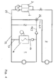
- Fig. 6
- Einrichtung nach Fig. 1 in einer praktischen Ausführung.
- Fig. 1
- a device equipped with several condensing boilers for supplying heat to two consumer circuits located at different temperature levels,
- Fig. 2
- a device equipped with several condensing boilers for the supply of heat for two separate temperature circuits and coupled via a heat exchanger consumer circuits,
- Fig. 3
- a device equipped with several condensing boilers for supplying heat with a consumer circuit for heating located at a low temperature level and with a consumer circuit for the hot water supply from drinking water at a higher temperature level, with a return part feed to the condensing boiler in the heating circuit at a raised temperature level,
- Fig. 4
- a further circuit variant of FIG. 1,
- Fig. 5
- Device according to Fig. 2 in a practical embodiment,
- Fig. 6
- Device according to Fig. 1 in a practical embodiment.
Eine erfindungsgemäß ausgestaltete Wärmeversorgungsanlage weist zwei Verbraucherkreise auf. Der eine Verbraucherkreis 1 dient zur Bereitstellung von Wärmeenergie für eine nicht dargestellte Beheizungsanlage. Der zweite vorhandene Verbraucherkreis 2 dient zur Bereitstellung von Wärmeenergie zur Warmwasserbereitung zur Bereitstellung von Warmwasser in einen nicht dargestellten Abnehmersystem. In dem Verbraucherkreis 2 für die Warmwasserbereitstellung befinden sich zwei als Brennwertthermen 3 und 4 ausgebildete Wärmeerzeuger. Die beiden Brennwertthermen 3 und 4 sind hydraulisch parallel geschaltet und liegen in einem Vorlauf 5 des Verbraucherkreises 2. Über die Vorlaufleitung 5 werden in Reihe liegende Wärmespeicher 6 und 7 und wahlweise ein erster der Warmwassererzeugung dienender Wärmetauscher 8 und ein mit diesem Wärmetauscher 8 in Reihe liegender, gleichfalls der Warmwasseraufbereitung dienender Wärmetauscher 9 vorlaufseitig beaufschlagt. In der Vorlaufleitung 5 ist ein temperaturgesteuertes Dreiwegeventil 10 vorgesehen, das hinter einer Einspeiseleitung 11 zum Wärmespeicher 7 angeordnet ist, das sowohl den Volumenstrom zum ersten Wärmetauscher 8 regulieren kann und andererseits einen Bypass 12 zur Rücklaufleitung 13 beaufschlagen kann. Die Rücklaufleitung 13 ist rücklaufseitig mit dem Wärmespeicher 6 verbunden.A heat supply system designed according to the invention has two consumer circuits. The one
In der Vorlaufleitung 5 ist eine Förderpumpe 14 vorgesehen, die vorteilhafter Weise zwischen dem Dreiwegeventil 10 und dem ersten Wärmetauscher 8 angeordnet ist.In the
In der Rücklaufleitung 13 ist ein Wärmetauscher 15 vorgesehen, der sich nach der Einbindung der Speicherrücklaufleitung 13.2 in die Rücklaufleitung 13.1 und vor dem Eintritt in die Brennwerttherme 4 befindet.In the return line 13, a
Über diesen Wärmetauscher 15 erfolgt ein Wärmeenergieaustausch zwischen dem Verbraucherkreis 1 und dem Verbraucherkreis 2.About this
In dem Verbraucherkreis 2 befindet sich zur Breitstellung von Heizleistung für die nicht dargestellte Heizungsanlage ein aus einem Brennwertkessel größerer Leistung bestehender Wärmeerzeuger 16. Dieser Brennwertkessel 16 ist mit seinem Vorlauf 17 über ein Dreiwegeventil 18 sowohl mit einer Vorlaufleitung 19.1 einer nicht dargestellten Heizungsanlage als auch mit einer Einspeiseleitung 19.2 zum Wärmetauschervorlauf 20 des Wärmetauschers 15 verbunden. Der Wärmetauscherrücklauf 21 ist mit einer Rücklaufleitung 22.1 mit dem Kesselrücklauf 23 wie auch mit der Rücklaufleitung 24 aus dem Verbraucherkreis 1 der Beheizungsanlage verbunden. Vor der Einspeisung der Rücklaufleitung 24 des Verbraucherkreises 1 der nicht dargestellten Heizungseinrichtung in den Kesselvorlauf 17 des Brennwertkessels 16 ist eine Förderpumpe 25 vorgesehen.In the
Eine Alternative zur Ausführungsform nach Fig. 6 zeigt die in Fig. 3 dargestellte, durch das Stellventil 26 mit Umschaltfunktion vollziehbare wahlweise Zuführung aus dem Rücklauf 13.1 des Verbraucherkreises 2 mit dem gegenüber dem Verbraucherkreis 1 angehobenen Temperaturniveau in die gegenüber dem Rücklauf 22 des Wärmeerzeugers 16 angehobene Rücklauftemperaturebene liegende Rücklaufkesseleinspeisung 28 des Wärmeerzeugers 16. Mit dieser Lösungsvariante soll im Betrieb eine wirtschaftliche Verbindung der zwei auf unterschiedlichen Temperaturebenen liegenden Verbraucherkreise 1; 2 unterstützt werden.An alternative to the embodiment of Fig. 6 shows the illustrated in Fig. 3, by the
Nach einer weiteren praktischen Ausführungsform des erfinderischen Grundgedankens nach Fig. 6 sind die Versorgungskreise 1 und 2 nicht über einen Wärmetauscher 15 hydraulisch getrennt, sondern der Rücklauf 13.1 des Versorgungskreises 2 mit einem gegenüber dem Versorgungskreis 1 höheren Temperaturniveaus ist über ein Stellventil 26 mit Umschaltfunktion mit der Einspeiseleitung 19.2 zur Vorlaufleitung 19.1 des Verbraucherkreises 1 verbunden. Weiterhin ist der Rücklauf 13.1 aus dem Verbraucherkreis 2 über das Stellventil 26 mit Umschaltfunktion sowohl mit der Rücklaufeinspeisung 27 zu den Brennwertthermen 3; 4 als auch mit dem Rücklauf 22.1 des Versorgungskreises 1 verbunden. Über das Stellventil 26 mit Umschaltfunktion wird bewirkt, daß der Verbraucherkreis 1 bei Stillstand des Brennwertkessels 16 mit Wärmeenergie versorgt werden kann. Dies hat eine praktische Bedeutung in Übergangszeiten, wo der Brennwertkessel 16 noch nicht oberhalb der unteren Modulationsgrenze im Brennwertbereich betrieben werden kann. Andererseits wird in dem Betriebszustand des Brennwertkessels 16 oberhalb der Modulationsgrenze im Dauerbetrieb für die Wärmeversorgung des Verbraucherkreises 1 bewirkt, daß die Temperaturen im Rücklauf 13.1 aus dem Verbraucherkreis 2 durch Einspeisung aus dem Rücklauf 22.1 über eine Vermischung der Rücklaufströme aus dem Rücklauf 13.1 des Verbraucherkreises 2 und aus dem Rücklauf 22.1 des Verbraucherkreises 1 auf Temperaturen zurückgeführt werden, die den wirtschaftlichen Betrieb der Brennwertthermen 3; 4 garantieren.According to another practical embodiment of the inventive concept of FIG. 6, the
Diese praktizierbare Ausführungsform zeigt Grenzen, die darin liegen, daß diese Anlagenvariante nicht über einen Druckbereich von PN = 3 eingesetzt werden kann. Die Brennwertthermen 3; 4 sind nicht für höhere Drücke ausgelegt. Für Druckbereiche über PN=3 bietet sich die hydraulische Trennung der beiden Verbraucherkreise 1 und 2 über einen Wärmetauscher 21 an.This practicable embodiment shows limits, which lie in the fact that this system variant can not be used over a pressure range of P N = 3. The condensing
Der Vorteil der in zwei Varianten ausgeführten erfinderischen Grundlösung besteht darin, daß grundsätzlich der Einsatz von Brennwertkesseln und Brennwertthermen immer im Brennwerteffekt vollzogen werden kann und der Brennwertkessel 16 im Verbraucherkreis 1 nicht mehr tacktet. Außerdem ist die Wärmeversorgung im Sommer und in den Übergangsperioden über die im Versorgungskreis 2 liegenden Brennwertthermen 3; 4 wirtschaftlich gesichert.The advantage of running in two variants inventive basic solution is that in principle the use of condensing boilers and condensing boilers can always be performed in the condensing effect and the condensing
Durch die Verwendung von Brennwertthermen kann eine Leistungsanpassung der erfindungsgemäßen Einrichtung zur Wärmeenergieversorgung von mindestens zwei getrennten Verbtaucherkreisen für Heizungs- und Warmwassererzeugung durch eine beliebige Erweiterung erfolgen, da zu den bereits vorhandenen Brennwertthermen weitere parallel geschaltet und damit nachrüstbar angeordnet werden können.Through the use of condensing boilers, a power adjustment of the device according to the invention for thermal energy supply of at least two separate Verbtaucherkreisen for heating and hot water production can be done by any extension, since the already existing condensing boilers connected in parallel and thus can be retrofitted.
Mit der erfindungsgemäß ausgebildeten Einrichtung zur Wärmeenergieversorgung wird es ermöglicht, den als Brennwertkessel ausgebildeten Wärmeerzeuger 2 und die Brennwertthermen 3; 4 mit dem vollen Brennwerteffekt, d.h. bei einer definierten niedrigen Rücklauftemperatur zu betreiben. Damit werden Prüfstandswerte der Wärmeerzeuger fast erreicht.With the inventively designed device for heat energy supply, it is possible, designed as a condensing
- 11
- Verbraucherkreisconsumer circuit
- 22
- Verbraucherkreisconsumer circuit
- 33
- BrennwertthermeBrennwerttherme
- 44
- BrennwertthermeBrennwerttherme
- 55
- Vorlaufleitungsupply line
- 66
- Wärmespeicherheat storage
- 77
- Wärmespeicherheat storage
- 88th
- Wärmetauscherheat exchangers
- 99
- Wärmetauscherheat exchangers
- 1010
- 3-Wegeventil3-way valve
- 1111
- Speicherleitungstorage line
- 1212
- Bypaßleitungbypass line
- 13.113.1
- RücklaufleitungReturn line
- 13.213.2
- SpeicherrücklaufCylinder return
- 1414
- Förderpumpefeed pump
- 1515
- Wärmetauscherheat exchangers
- 1616
- Brennwertkesselcondensing boilers
- 1717
- Vorlaufleader
- 1818
- 3-Wegeventil3-way valve
- 19.119.1
- Vorlaufleitungsupply line
- 19.219.2
- Einspeiseleitungfeeder
- 2020
- Wärmetauschervorlaufheat exchange forward
- 2121
- WärmetauscherrücklaufHeat exchanger's return
- 2222
- RücklaufleitungReturn line
- 2323
- Rücklaufreturns
- 2424
- Rücklaufreturns
- 2525
- Förderpumpefeed pump
- 2626
- StellventilControl valve
- 2727
- RücklaufeinspeisungReturn line
- 2828
- RücklaufkesseleinspeisungReturn boiler feed
Claims (9)
Applications Claiming Priority (1)
| Application Number | Priority Date | Filing Date | Title |
|---|---|---|---|
| DE102005046080A DE102005046080B4 (en) | 2005-09-26 | 2005-09-26 | Device for supplying heat with at least two separate, lying on different temperature levels consumer circuits with at least one heat generator and method for operating the device |
Publications (2)
| Publication Number | Publication Date |
|---|---|
| EP1795817A2 true EP1795817A2 (en) | 2007-06-13 |
| EP1795817A3 EP1795817A3 (en) | 2013-02-27 |
Family
ID=37698315
Family Applications (1)
| Application Number | Title | Priority Date | Filing Date |
|---|---|---|---|
| EP06018416A Withdrawn EP1795817A3 (en) | 2005-09-26 | 2006-09-02 | Installation for supplying heat with at least two separated circuits, working at different temperature, with at least one heat source and method for operating the same |
Country Status (2)
| Country | Link |
|---|---|
| EP (1) | EP1795817A3 (en) |
| DE (1) | DE102005046080B4 (en) |
Cited By (1)
| Publication number | Priority date | Publication date | Assignee | Title |
|---|---|---|---|---|
| CN108916968A (en) * | 2018-08-24 | 2018-11-30 | 沈阳世杰电器有限公司 | A kind of heating system with solid thermal energy storage device |
Families Citing this family (2)
| Publication number | Priority date | Publication date | Assignee | Title |
|---|---|---|---|---|
| DE102007063137A1 (en) | 2007-12-24 | 2009-06-25 | Lang, Jürgen, Dipl.-Ing. | Heat energy supply mechanism for use during production of warm water from drinking water, has heat energy supply circuits, where one of supply circuits is connected to one of heat generators with supply line and return line |
| CZ31064U1 (en) * | 2017-01-27 | 2017-10-03 | Almeva Ag | A combined system of service water heating and a heating medium for domestic heating |
Citations (5)
| Publication number | Priority date | Publication date | Assignee | Title |
|---|---|---|---|---|
| DE2856018A1 (en) * | 1978-12-23 | 1980-07-10 | Bbc Brown Boveri & Cie | ARRANGEMENT FOR CONTROLLING THE DISTRIBUTION OF HEAT IN A SOLAR HOUSE |
| DE9104689U1 (en) * | 1991-04-17 | 1991-06-20 | Höfer, Volker Maria, 5340 Bad Honnef | Device for recovering heat from the exhaust gases from combustion plants |
| CH689173A5 (en) * | 1994-05-27 | 1998-11-13 | Unical Ag | Hot water central heating circuit |
| DE10055335A1 (en) * | 2000-11-08 | 2002-05-29 | Pro Solar Energietechnik Gmbh | Solar heating unit incorporates buffer store, heat-generator connected to accumulator, and heat-exchanger |
| DE10349258B3 (en) * | 2003-10-20 | 2005-02-17 | Vertrieb und Großhandel von Heizungs-, Sanitär- und Elektroerzeugnissen | Heat supply plant for heating system has two heat creators in series, one for heating, other for hot water |
Family Cites Families (2)
| Publication number | Priority date | Publication date | Assignee | Title |
|---|---|---|---|---|
| DE10244339A1 (en) * | 2002-09-24 | 2004-04-01 | Robert Bosch Gmbh | Heating system for buildings has hot water tank and a warm water tank which is divided into a low-temperature reservoir and a high temperature reservoir for better use of energy, especially solar energy |
| DE102004038768B4 (en) * | 2003-10-20 | 2008-03-06 | Vertrieb und Großhandel von Heizungs-, Sanitär- und Elektroerzeugnissen | Heat supply system with at least two heat generators for a heating system and a device for hot water production and method for the consumption-dependent control of the heat generator |
-
2005
- 2005-09-26 DE DE102005046080A patent/DE102005046080B4/en not_active Expired - Fee Related
-
2006
- 2006-09-02 EP EP06018416A patent/EP1795817A3/en not_active Withdrawn
Patent Citations (5)
| Publication number | Priority date | Publication date | Assignee | Title |
|---|---|---|---|---|
| DE2856018A1 (en) * | 1978-12-23 | 1980-07-10 | Bbc Brown Boveri & Cie | ARRANGEMENT FOR CONTROLLING THE DISTRIBUTION OF HEAT IN A SOLAR HOUSE |
| DE9104689U1 (en) * | 1991-04-17 | 1991-06-20 | Höfer, Volker Maria, 5340 Bad Honnef | Device for recovering heat from the exhaust gases from combustion plants |
| CH689173A5 (en) * | 1994-05-27 | 1998-11-13 | Unical Ag | Hot water central heating circuit |
| DE10055335A1 (en) * | 2000-11-08 | 2002-05-29 | Pro Solar Energietechnik Gmbh | Solar heating unit incorporates buffer store, heat-generator connected to accumulator, and heat-exchanger |
| DE10349258B3 (en) * | 2003-10-20 | 2005-02-17 | Vertrieb und Großhandel von Heizungs-, Sanitär- und Elektroerzeugnissen | Heat supply plant for heating system has two heat creators in series, one for heating, other for hot water |
Cited By (1)
| Publication number | Priority date | Publication date | Assignee | Title |
|---|---|---|---|---|
| CN108916968A (en) * | 2018-08-24 | 2018-11-30 | 沈阳世杰电器有限公司 | A kind of heating system with solid thermal energy storage device |
Also Published As
| Publication number | Publication date |
|---|---|
| DE102005046080B4 (en) | 2007-09-20 |
| EP1795817A3 (en) | 2013-02-27 |
| DE102005046080A1 (en) | 2007-04-05 |
Similar Documents
| Publication | Publication Date | Title |
|---|---|---|
| EP2154436B1 (en) | Method and device for heat utilization | |
| EP2363650A2 (en) | Heater group with jet pump regulation | |
| EP2138775A2 (en) | Assembly and method for preparing warm drinking water with a heater | |
| DE102009004501A1 (en) | Heat pump i.e. directly evaporating geo heat pump, for raising temperature level of e.g. water source, has refrigerant circuit and heat source cycle with set of heat sources, where refrigerant circuit has two evaporating heat exchangers | |
| EP1795817A2 (en) | Installation for supplying heat with at least two separated circuits, working at different temperature, with at least one heat source and method for operating the same | |
| EP2287547B1 (en) | Heat pump and method for regulating the source entry temperature of the heat pump | |
| EP2307812A1 (en) | Line arrangement for tempering two tempering circuits of buildings | |
| AT505065B1 (en) | PROCESS FOR PROVIDING THERMAL ENERGY | |
| DE102006023627B4 (en) | solar system | |
| DE3311127C2 (en) | Method for controlling heat generators connected in a network and connected to a buffer storage tank and arrangement for carrying out the method | |
| DE2916530A1 (en) | METHOD AND DEVICE FOR GENERATING AND DISTRIBUTING THERMAL ENERGY WITH COMPENSATION TRANSFER IN GEOTHERMAL LAYERS | |
| DE102007048728B4 (en) | Heating boiler, heating system and method for operating a heating system, in particular for solar heating support | |
| AT511697B1 (en) | DEVICE FOR HEATING HOT WATER | |
| DE19527830C2 (en) | Process for operating a heating system and heating system | |
| WO2010094282A2 (en) | Heating or cooling installation and method for operating a heating or cooling installation | |
| DE102008061135A1 (en) | Method for controlling or regulating a heating system and heating system | |
| DE10349258B3 (en) | Heat supply plant for heating system has two heat creators in series, one for heating, other for hot water | |
| EP0961082B1 (en) | Installation for heating and hot water production | |
| EP1526338B1 (en) | Heat supply unit with at least two heat generators and method for controlling the heat generators depending on the consumption | |
| DE20305438U1 (en) | Collection/distribution unit for the hot water in a heating installation, for a building, has a four-way valve in the connection to the heating circuits to give flows of different temperatures and a backflow | |
| EP2189730A2 (en) | System for supplying a heat consumer and method for operating such a system | |
| DE102009038738A1 (en) | Heating system for providing hot water supply in building, has valve formed as controlled mixer, where heating circuit medium flowing over line from buffer storage is mixedly supplied with heating circuit medium from return port over valve | |
| AT526249B1 (en) | Method for temperature control of building rooms | |
| EP3460340B1 (en) | Method for providing heat, heat recovery system and heat provision unit | |
| EP1788314A1 (en) | Space heating system with more than one heat source |
Legal Events
| Date | Code | Title | Description |
|---|---|---|---|
| PUAI | Public reference made under article 153(3) epc to a published international application that has entered the european phase |
Free format text: ORIGINAL CODE: 0009012 |
|
| AK | Designated contracting states |
Kind code of ref document: A2 Designated state(s): AT BE BG CH CY CZ DE DK EE ES FI FR GB GR HU IE IS IT LI LT LU LV MC NL PL PT RO SE SI SK TR |
|
| AX | Request for extension of the european patent |
Extension state: AL BA HR MK YU |
|
| RAP1 | Party data changed (applicant data changed or rights of an application transferred) |
Owner name: VERTRIEB UND GROSSHANDEL VON HEIZUNGS-, SANITAER- |
|
| RIC1 | Information provided on ipc code assigned before grant |
Ipc: F24D 3/02 20060101ALI20121005BHEP Ipc: F24D 3/08 20060101ALI20121005BHEP Ipc: F24D 12/02 20060101AFI20121005BHEP Ipc: F24D 19/10 20060101ALI20121005BHEP |
|
| PUAL | Search report despatched |
Free format text: ORIGINAL CODE: 0009013 |
|
| AK | Designated contracting states |
Kind code of ref document: A3 Designated state(s): AT BE BG CH CY CZ DE DK EE ES FI FR GB GR HU IE IS IT LI LT LU LV MC NL PL PT RO SE SI SK TR |
|
| AX | Request for extension of the european patent |
Extension state: AL BA HR MK RS |
|
| RIC1 | Information provided on ipc code assigned before grant |
Ipc: F24D 3/08 20060101ALI20130122BHEP Ipc: F24D 12/02 20060101AFI20130122BHEP Ipc: F24D 3/02 20060101ALI20130122BHEP Ipc: F24D 19/10 20060101ALI20130122BHEP |
|
| RAP1 | Party data changed (applicant data changed or rights of an application transferred) |
Owner name: SCHRAMM, BRUNO |
|
| AKY | No designation fees paid | ||
| REG | Reference to a national code |
Ref country code: DE Ref legal event code: R108 |
|
| REG | Reference to a national code |
Ref country code: DE Ref legal event code: R108 Effective date: 20131030 |
|
| STAA | Information on the status of an ep patent application or granted ep patent |
Free format text: STATUS: THE APPLICATION IS DEEMED TO BE WITHDRAWN |
|
| 18D | Application deemed to be withdrawn |
Effective date: 20130828 |