EP2138775A2 - Assembly and method for preparing warm drinking water with a heater - Google Patents
Assembly and method for preparing warm drinking water with a heater Download PDFInfo
- Publication number
- EP2138775A2 EP2138775A2 EP09157072A EP09157072A EP2138775A2 EP 2138775 A2 EP2138775 A2 EP 2138775A2 EP 09157072 A EP09157072 A EP 09157072A EP 09157072 A EP09157072 A EP 09157072A EP 2138775 A2 EP2138775 A2 EP 2138775A2
- Authority
- EP
- European Patent Office
- Prior art keywords
- fluid
- drinking water
- heat exchanger
- circuit
- primary
- Prior art date
- Legal status (The legal status is an assumption and is not a legal conclusion. Google has not performed a legal analysis and makes no representation as to the accuracy of the status listed.)
- Withdrawn
Links
- 239000003651 drinking water Substances 0.000 title claims abstract description 67
- 235000020188 drinking water Nutrition 0.000 title claims abstract description 67
- 238000000034 method Methods 0.000 title claims abstract description 9
- 239000012530 fluid Substances 0.000 claims abstract description 115
- 230000001419 dependent effect Effects 0.000 claims abstract description 10
- XLYOFNOQVPJJNP-UHFFFAOYSA-N water Substances O XLYOFNOQVPJJNP-UHFFFAOYSA-N 0.000 claims description 31
- 238000010438 heat treatment Methods 0.000 claims description 12
- 230000001105 regulatory effect Effects 0.000 claims description 4
- 230000002308 calcification Effects 0.000 claims description 3
- 239000008236 heating water Substances 0.000 claims description 3
- 230000002265 prevention Effects 0.000 claims description 2
- 230000008569 process Effects 0.000 claims description 2
- 238000003860 storage Methods 0.000 abstract description 14
- 238000010079 rubber tapping Methods 0.000 description 7
- 238000012546 transfer Methods 0.000 description 7
- 238000007726 management method Methods 0.000 description 5
- 238000013517 stratification Methods 0.000 description 4
- 230000006399 behavior Effects 0.000 description 3
- 238000013461 design Methods 0.000 description 3
- 230000020169 heat generation Effects 0.000 description 3
- 230000004913 activation Effects 0.000 description 2
- 230000008901 benefit Effects 0.000 description 2
- 238000009434 installation Methods 0.000 description 2
- 239000004449 solid propellant Substances 0.000 description 2
- 238000003809 water extraction Methods 0.000 description 2
- 241000894006 Bacteria Species 0.000 description 1
- 241000589248 Legionella Species 0.000 description 1
- 208000007764 Legionnaires' Disease Diseases 0.000 description 1
- 241001676573 Minium Species 0.000 description 1
- 229910000831 Steel Inorganic materials 0.000 description 1
- 239000000654 additive Substances 0.000 description 1
- 238000013459 approach Methods 0.000 description 1
- 230000033228 biological regulation Effects 0.000 description 1
- 230000005540 biological transmission Effects 0.000 description 1
- 230000008859 change Effects 0.000 description 1
- 238000010924 continuous production Methods 0.000 description 1
- 238000011217 control strategy Methods 0.000 description 1
- 238000001816 cooling Methods 0.000 description 1
- 238000005260 corrosion Methods 0.000 description 1
- 230000007797 corrosion Effects 0.000 description 1
- 238000009826 distribution Methods 0.000 description 1
- 238000004146 energy storage Methods 0.000 description 1
- 238000005516 engineering process Methods 0.000 description 1
- 230000006870 function Effects 0.000 description 1
- 230000003993 interaction Effects 0.000 description 1
- 230000005923 long-lasting effect Effects 0.000 description 1
- 238000012423 maintenance Methods 0.000 description 1
- 238000004519 manufacturing process Methods 0.000 description 1
- 238000005259 measurement Methods 0.000 description 1
- 238000003303 reheating Methods 0.000 description 1
- 230000002269 spontaneous effect Effects 0.000 description 1
- 229910001220 stainless steel Inorganic materials 0.000 description 1
- 239000010935 stainless steel Substances 0.000 description 1
- 239000010959 steel Substances 0.000 description 1
- 238000010792 warming Methods 0.000 description 1
- 238000005406 washing Methods 0.000 description 1
Images

Classifications
-
- F—MECHANICAL ENGINEERING; LIGHTING; HEATING; WEAPONS; BLASTING
- F24—HEATING; RANGES; VENTILATING
- F24D—DOMESTIC- OR SPACE-HEATING SYSTEMS, e.g. CENTRAL HEATING SYSTEMS; DOMESTIC HOT-WATER SUPPLY SYSTEMS; ELEMENTS OR COMPONENTS THEREFOR
- F24D17/00—Domestic hot-water supply systems
- F24D17/0078—Recirculation systems
-
- F—MECHANICAL ENGINEERING; LIGHTING; HEATING; WEAPONS; BLASTING
- F24—HEATING; RANGES; VENTILATING
- F24D—DOMESTIC- OR SPACE-HEATING SYSTEMS, e.g. CENTRAL HEATING SYSTEMS; DOMESTIC HOT-WATER SUPPLY SYSTEMS; ELEMENTS OR COMPONENTS THEREFOR
- F24D17/00—Domestic hot-water supply systems
- F24D17/0026—Domestic hot-water supply systems with conventional heating means
- F24D17/0031—Domestic hot-water supply systems with conventional heating means with accumulation of the heated water
-
- F—MECHANICAL ENGINEERING; LIGHTING; HEATING; WEAPONS; BLASTING
- F24—HEATING; RANGES; VENTILATING
- F24D—DOMESTIC- OR SPACE-HEATING SYSTEMS, e.g. CENTRAL HEATING SYSTEMS; DOMESTIC HOT-WATER SUPPLY SYSTEMS; ELEMENTS OR COMPONENTS THEREFOR
- F24D17/00—Domestic hot-water supply systems
- F24D17/0073—Arrangements for preventing the occurrence or proliferation of microorganisms in the water
-
- F—MECHANICAL ENGINEERING; LIGHTING; HEATING; WEAPONS; BLASTING
- F24—HEATING; RANGES; VENTILATING
- F24D—DOMESTIC- OR SPACE-HEATING SYSTEMS, e.g. CENTRAL HEATING SYSTEMS; DOMESTIC HOT-WATER SUPPLY SYSTEMS; ELEMENTS OR COMPONENTS THEREFOR
- F24D19/00—Details
- F24D19/10—Arrangement or mounting of control or safety devices
- F24D19/1006—Arrangement or mounting of control or safety devices for water heating systems
- F24D19/1051—Arrangement or mounting of control or safety devices for water heating systems for domestic hot water
-
- Y—GENERAL TAGGING OF NEW TECHNOLOGICAL DEVELOPMENTS; GENERAL TAGGING OF CROSS-SECTIONAL TECHNOLOGIES SPANNING OVER SEVERAL SECTIONS OF THE IPC; TECHNICAL SUBJECTS COVERED BY FORMER USPC CROSS-REFERENCE ART COLLECTIONS [XRACs] AND DIGESTS
- Y02—TECHNOLOGIES OR APPLICATIONS FOR MITIGATION OR ADAPTATION AGAINST CLIMATE CHANGE
- Y02B—CLIMATE CHANGE MITIGATION TECHNOLOGIES RELATED TO BUILDINGS, e.g. HOUSING, HOUSE APPLIANCES OR RELATED END-USER APPLICATIONS
- Y02B10/00—Integration of renewable energy sources in buildings
- Y02B10/20—Solar thermal
-
- Y—GENERAL TAGGING OF NEW TECHNOLOGICAL DEVELOPMENTS; GENERAL TAGGING OF CROSS-SECTIONAL TECHNOLOGIES SPANNING OVER SEVERAL SECTIONS OF THE IPC; TECHNICAL SUBJECTS COVERED BY FORMER USPC CROSS-REFERENCE ART COLLECTIONS [XRACs] AND DIGESTS
- Y02—TECHNOLOGIES OR APPLICATIONS FOR MITIGATION OR ADAPTATION AGAINST CLIMATE CHANGE
- Y02B—CLIMATE CHANGE MITIGATION TECHNOLOGIES RELATED TO BUILDINGS, e.g. HOUSING, HOUSE APPLIANCES OR RELATED END-USER APPLICATIONS
- Y02B10/00—Integration of renewable energy sources in buildings
- Y02B10/70—Hybrid systems, e.g. uninterruptible or back-up power supplies integrating renewable energies
Definitions
- the invention relates to an arrangement for providing warm drinking water with a primary circuit with a fluid, a hot or hot fluid-providing device having a buffer memory with temperature-dependent stratified areas of the primary fluid, and a conveyor for the fluid, with a secondary circuit for the drinking water to be heated with a heat exchanger for transferring heat from the fluid of the primary circuit to the drinking water in the secondary circuit, with a line in the primary circuit, which returns fluid from the heat exchanger to the device, with a control device for the conveyor, and with at least one temperature sensor in the primary circuit or secondary circuit, the measured values be supplied to the control device.
- the invention also relates to a method for providing warm drinking water in such plants.
- an economically much more meaningful and at the same time more environmentally friendly solution can be found in systems that work with a drinking water storage tank.
- an additional storage tank is provided, can be stored in the hot water.
- the drinking water storage tank is sized so that it is readily capable of covering peak loads.
- the heat generation can here be made significantly smaller, in order to replace spontaneously with peak load consumed hot drinking water over a longer period again.
- a high hot water comfort can be provided.
- the contents of the storage tank must always be kept at a minimum of 60 ° C to avoid hygienic risks.
- high temperatures are not economically viable, especially since they can then no longer be combined with solar systems, condensing boilers and the like.
- the drinking water storage must also be performed corrosion resistant, such as enameled steel or stainless steel, which leads to more expensive systems and also requires a considerable amount of space.
- a primary fluid is provided in a heater side, for example buffer memory, said buffer approximately as from the EP 0 384 423 B1 known layered memory can be constructed.
- the heat generation in this primary fluid can be done in any form by solar heating, geothermal, cogeneration, solid fuel boilers, etc. Hygienically, these primary fluid circuits are not critical because the primary fluid is not used as drinking water and may also contain any additives.
- a hot water station which has a heat exchanger, for example a plate heat exchanger, can be connected to the buffer tank. If necessary, the primary fluid flows through this heat exchanger and discharges in it the required heat to the drinking water to be heated.
- a heat exchanger for example a plate heat exchanger
- Such systems are very hygienic, have a relatively small footprint, since the buffer for the heating system is needed anyway, and are usually relatively inexpensive to manufacture.
- the line of the primary circuit in the region between the heat exchanger and the device has a plurality of parallel strands, that in each of the parallel strands at least one conveyor is arranged, that the plurality of parallel strands of the line respectively sandwiching the fluid into regions of the buffer reservoir of the device that have a different temperature, and that the control of the delivery devices in the parallel strands by the control device is possible differently depending on the determined temperature of the fluid in the conduit for each delivery device.
- This object is achieved in a generic method according to the invention in that the fluid of the primary circuit is performed in the region between the heat exchanger and the device in several parallel strands that each of these parallel strands makes a separate promotion of the fluid that the fluids from the parallel Strands are stacked in areas of the buffer memory of the device with different temperature, and that the control of the conveyors in the parallel strands are controlled differently by the control device depending on the detected temperature of the fluid in the conduit for each conveyor.
- a division of the return flow of the primary fluid from the heat exchanger to at least two different flow paths now takes place.
- Each of these two flow paths contains a conveying device, in particular a circulating pump, which is in particular speed-controlled.
- These two (or more) circulation pumps run independently of each other.
- In each of the two sub-strands is now preferably a pump.
- These pumps may be provided with a downstream check valve to prevent mis-circulation.
- parallel strands is of course not to be understood in the strict geometric sense, but fluidically so that these two strands form parts of the line from the heat exchanger to the device and alternatives for the way that can take a molecule of the primary fluid.
- the hot or hot fluid-providing device has a buffer memory with temperature-dependent stratified areas of the primary fluid and if the plurality of parallel strands of the line respectively embed the fluid in areas of the buffer memory of the device which have a different temperature.
- the primary fluid in the heat exchanger is a very large part of its heat energy taken.
- the primary fluid thus leaves the heat exchanger in a relatively cold state. It is then passed through one of the two sub-strands, namely by the partial strand provided for cold primary fluid back into the store and there layered directly into the lower area.
- the primary fluid In the buffer reservoir, the primary fluid is normally in a stratified form, with the colder areas of the primary fluid at the bottom and the warmer areas of the primary fluid at the top of the buffer, corresponding to the density distributions of the primary fluid.
- feeding the cold primary fluid into the lower region does not disturb this stratification.
- the circulating pump in this cold sub-string is dimensioned according to the peak power in the dispensing operation, which is usually much larger than the circulation capacity. However, this peak power is much less frequently called as the circulation power.
- the primary fluid flow occurring in this case is now passed through the second partial strand.
- the pump of this sub-string can be designed much smaller than the first-mentioned pump usually.
- the design corresponds to a normal circulation load. Due to the expected long pump running times, speed-controllable high-efficiency pumps with EC motors should be used here in particular.
- This second sub-string is led into the storage area about the same temperature.
- the significantly warmer primary fluid matches its temperature exactly in this area of the stratified primary fluid quantities.
- This temperature-dependent stratification can be approximately due to the EP 0 384 423 B! be produced known layers or elements.
- a circulation circuit is provided for the secondary circuit, which has a conveyor, if the conveyor is equipped to promote a variable volume flow, and if the circulation circuit is designed so that it constantly provides already heated drinking water to a hot water outlet of the secondary circuit ,
- the conveyor is connected to the control device and if the control device actively influences a promotion of the volume flow in the circulation circuit to achieve a high control quality of hot water outlet and / or to prevent stagnation in the secondary circuit for Verkaltungsvorbefingung.
- variable setting of the volume flows makes it possible to achieve outlet temperatures at a hot water outlet in a targeted manner.
- the specific return temperature as well as the volume flows of the drinking water and the circulating water can be detected by corresponding sensors. This allows the two (or more) To control conveyors in the different strands as needed.
- Also on the side of the primary circuit sensors can be provided which detect the temperature and / or the flow rate.
- a temperature sensor in the return line from the heat exchanger to the device can be used, which measures directly whether now just strongly or less strongly cooled primary fluid flows in the line. If this temperature sensor or, to put it concretely, the control device connected to it detects a change in temperature, then it switches to the other pump in each case.
- volume flow measuring devices can also be used. Although it is possible to provide a control even without volume flow measuring devices, but this improves the possibilities, for example, to show an energy demand.
- a separate temperature sensor in the return line is dispensed with, and measured values which a temperature sensor recognizes in the secondary circuit are used instead. This determines whether hot water is being tapped right now or not.
- a separate temperature sensor in the return line is dispensed with, and measured values which a temperature sensor recognizes in the secondary circuit are used instead. This determines whether hot water is being tapped right now or not.
- such an embodiment is used only in special cases.
- a control device recognizes whether and which temperature and which volume flows in the return line of the primary fluid can be consistently determined from this knowledge so that it can also decide which of the two pumps in the partial strands should just run.
- the invention relies in particular on a combination of a buffer memory on the one hand and a certain form of direct pass on the other hand.
- the heating of the drinking water as well as the circulation volume flow to the desired hot water temperature takes place via a heat exchanger, such as a plate heat exchanger, in a continuous process.
- a separate drinking water storage is not required according to the invention.
- the various components can be kept very handy in standardized form, such as in prefabricated stations in conjunction with a corresponding system control. With an identical system structure, different stations from different desired performance classes can be provided right down to the megawatt range.
- the buffer with its temperature-dependent layers can fully exploit its advantages and work as energy storage with fluctuating loads for drinking water and heating as well as fluctuating profits such as from a solar system.
- the system can be used particularly expediently with a buffer store, in which the primary fluid is at the same time heating water, ie at a buffer storage or buffer stratified storage tank filled with heating water.
- the valuable and always well-monitored food Drinking water is warmed just as it is being used, resulting in excellent hygienic properties.
- the content of the drinking water heater is reduced to one minium.
- the primary-side return flow rates are separated clean temperature-oriented, which can be realized very quickly by a corresponding sensor. This leads to a rapid and long-lasting cooling of the lower buffer area in the tap of drinking water. This is effective and this cold volume can be used for a time-delayed Nachfilvorgang also to an active control of the return temperature. Desired target temperatures can be controlled very precisely and the cold volume is at the same time available for increasing the system efficiency during solar heating.
- the temperature can be detected directly within the heat exchanger. This more direct information helps fluctuating hot water temperatures, in particular to avoid load changes and to achieve a precise control and regulation. In this way, it is also possible to measure whether, in the case of tapping stops in the heat exchanger, a temperature which is critical for calcification can be achieved by the transfer of residual heat to the primary fluid side.
- a circulation pump is used, which is also part of the station. It can preferably be speed-controlled directly by the control. Through this active operation of the circulation pump on the secondary or drinking water side a uniform hot water temperature is reached.
- the heat exchanger in particular a plate heat exchanger, is continuously flowed through. With an appropriate pump control, temperatures on the drinking water side of more than 60 ° can be avoided. This also gives active calcification prevention.
- the invention can also be used in drinking water systems without a circulation network. There, an outlet in the hot water pipe with return via the circulation connection of the station can be provided.
- a load-dependent flow through the heat exchanger in particular so a plate heat exchanger, allows. This allows an adapted use of the available plates and thus an optimal heat transfer with a minimization of the return temperature.
- plate heat exchangers are often operated in a very large power range. They then have to be designed for the peak load case. For a light load case, however, such a plate heat exchanger is then oversized.
- the plate heat exchanger consisting of a plurality of plates connected in parallel becomes then flows through each of the fluids at a relatively low flow rate. As a result, the heat transfer and thus also the effectiveness of the heat transfer deteriorates. The return temperature rises.
- the wiring of the plates in the interior of the plate heat exchanger is made load-dependent.
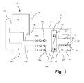
- FIG. 1 The purely schematic, only the most essential parts of the entire arrangement reproducing representation in FIG. 1 shows in the left half of a primary circuit 10, in the right half of a secondary circuit 20. A certain area of the arrangement shown is summarized with dashed lines as a heat station 1. This can be prefabricated to simplify assembly.
- the primary circuit 10 starts on the left with a device that provides hot or hot fluid, here a buffer memory 11. From this buffer memory 11, a line 12 leads to a heat exchanger 50. After passing through the heat exchanger 50 and the release of heat energy in the same runs the Fluid in the primary circuit 10 back via an output-side line 13 to the device 11, ie the buffer memory.
- a conveyor 14 in particular a pump is provided.
- the fluid passes from the upper region of the buffer memory 11 to the heat exchanger 50, from there through the line 13 then back into the lower region of the buffer memory 11, where it is layered or otherwise returned suitable.
- the secondary circuit 20 on the right side of the representation of FIG. 1 begins with a cold water supply line 22, with the cold drinking water (drinking water, washing water, etc.) is supplied to the heat exchanger 50.
- the heat energy of the current in countercurrent primary circuit 10 is received.
- the drinking water leaves the latter again and flows through an outlet-side line 23 to the hot water extraction point, the tapping point.
- the promotion in the secondary circuit can in principle be effected by the fact that the cold water supply is under pressure and the hot water extraction point by a cock locks this pressure if necessary.
- a circulation line 40 is provided in the secondary circuit 20.
- the circulation line 40 branches adjacent to the tapping point (not shown, right outside the heat station 1) and leads back to the cold water access line 22 immediately before the heat exchanger 50.
- a circulation conveyor 44 is provided in the form of a circulation pump. Also indicated is a temperature sensor 47 which measures the temperature in the circulation line 40.
- thermosensor 47 In addition to the temperature sensor 47, other sensor elements may be provided (not shown), such as a volumetric flow meter, in order to better detect the circulation load.
- the volume flow device or preferably the output signal of a temperature sensor 57 in the heat exchanger 50 gives a signal for the circulation pump 44, the drinking water in line 23 is out of the range deduct before the tap and promote through the circulation line 40 back in front of the heat exchanger 50.
- a control device 30 which will be discussed below is made possible, to adjust the tapping temperature constant and, if necessary, to detect the amount of heat delivered.
- the purpose of the circulation circuit 40 is not to let the cooled water after a certain time in the line 23 to flow out of the tap because the consumer wants there warm water and not cooled drinking water. He would not use this not wanted by him cooled drinking water and possibly just run off the line.
- the water currently flowing out of the heat exchanger 50 is warm because it has received heat energy from the primary circuit 10.
- the length of the line 23 and the flow behavior are known, so that very precisely the circulation pump 44 can be controlled so that exactly when it reaches desired heated drinking water at the tap this can also escape there.
- Temperature control values from the temperature sensors 47 or 57 or 27 can therefore be used for a control (or, more precisely, control or activation) of the delivery devices 14a, 14b, 14c, as well as measured values of volume flow measurements or other measured values which allow conclusions to be drawn about the current situation present situation or current load behavior.
- a control device 30 is indicated only schematically. This regulating device 30 is now connected to the conveying devices 14a, 14b, 14c and the temperature sensors 27, 47, 57 with data transmission lines, not shown, in order, on the one hand, to receive measured values and, on the other hand, to transmit corresponding control or regulating signals.
- a power supply for the conveyors 14a, 14b, 14c may be provided.
- each of these three branch lines 13a, 13b, 13c are each a conveyor 14a, 14b, 14c.
- These three conveyors are preferably pumps and are independent of one another and can be of different types and in particular of variably variable delivery rates.
- This buffer memory 11 is constructed as a layered memory, so that, as already mentioned above, the warmer areas of the primary fluid are higher up and the colder ones are further down.
- one of the conveyors 14 is turned on and the other two branches are blocked accordingly. Through this then no fluid flows or the fluid is in them.
- Relatively warm primary fluid in the conduit 13 is also conveyed into an area of the buffer accumulator 11 further up by switching on the uppermost conveyor 14c.
- the temperature of the primary fluid after exiting the heat exchanger 50 depends on whether the primary fluid in the heat exchanger 50 has released much or little heat energy to the secondary fluid in the secondary circuit 20. A lot of heat energy is released when at the tap at the end of the Line 23 lots of hot water is tapped. Relatively little heat energy is transferred in the heat exchanger 50, if only secondary fluid (ie drinking water) is kept in the circulation line 40 at a predetermined temperature, so with a relatively high temperature already enters the heat exchanger 50.
- a corresponding activation of the conveying devices 14a, 14b and 14c can therefore be carried out on the basis of a multiplicity of different measured values and findings.
- This control can also detect on the basis of the load behavior on the secondary circuit 20, if and what amount of volume flow should receive in the primary circuit 10. There are correlations between these temperature and volume insights.
- FIGS. 2 and 3 The details of a preferred embodiment of the heat exchanger 50 from the FIG. 1 are in the FIGS. 2 and 3 shown.
- the heat exchanger 50 thus has an inlet 51 for the primary fluid in the primary circuit 10 and an outlet 52 for the primary fluid in the primary circuit 10 after passing through the heat exchanger.
- hot primary fluid enters at inlet 51, while cooled or colder primary fluid exits at outlet 52 and then continues to flow in line 13 (see FIG FIG. 1 ).
- secondary fluid in the secondary circuit 20 enters the inlet 53 of the heat exchanger 50 via the line 22.
- the temperature of the secondary fluid is cold or cooled, as far as it is secondary fluid from the circulation circuit 40.
- the primary fluid flows from bottom to top, while the secondary fluid from top to bottom.
- the primary fluid and the secondary fluid there are corresponding contact surfaces (not shown) for transmitting the heat energy.
- the primary fluid flows within the heat exchanger 50 between a plurality of plates or fins which form channels therebetween.
- the Inflow takes place over the entire in the FIG. 2 illustrated length of the primary entry from the right to left edge of the heat exchanger.
- the secondary fluid flows from top to bottom through other comparable channels between corresponding plates and louvers.
- the region in which the primary fluid flows from the bottom to the top and the secondary fluid from top to bottom within the heat exchanger 50 is limited by the inflow depth in the horizontal direction of the primary fluid at the inlet 51 and the secondary fluid is restricted at the entrance 53, respectively.
- the element 60 has a ring 61 which on the right side in the FIG. 3 is shown and is provided for receiving the nozzle of the inlet openings 51 and 53 of the heat exchanger 50.
- the length of the guide struts 62 may be about one third of the total length of the heat exchanger 50.
- the guide struts 62 terminate at a non-return flap 63, which is formed as a butterfly-check flap and is arranged rotatably about a rotation axis 64 with a return spring.
- This butterfly check flap 63 can therefore serve, if correspondingly positioned within the inlet 51 or 53, to greatly reduce the further flow of the primary fluid or of the secondary fluid in the direction of the inlet. Then, the primary fluid and the secondary fluid flow mainly in this first third of the heat exchanger 50, while the entire rear region with only two thirds of the plates and channels only is permeated with a leakage current, and hardly transfers energy. For the flow velocity and thus the efficiency of the heat transfer is improved in the front third.
- the rear part of the heat transfer 50 is only slightly flowed through for an increased control quality on the primary side and for ensuring the hygiene on the secondary side in low load case.
Abstract
Description
Die Erfindung betrifft eine Anordnung zur Bereitstellung von warmem Trinkwassermit einem Primärkreislauf mit einem Fluid, einer warmes oder heißes Fluid bereitstellenden Einrichtung, die einem Pufferspeicher mit temperaturabhängig geschichteten Bereichen des Primärfluids aufweist, und einer Fördereinrichtung für das Fluid, mit einem Sekundärkreislauf für das zu erwärmende Trinkwasser, mit einem Wärmeübertrager zur Übertragung von Wärme vom Fluid des Primärkreislaufs auf das Trinkwasserim Sekundärkreislauf, mit einer Leitung im Primärkreislauf, die Fluid vom Wärmeübertrager zur Einrichtung zurückführt, mit einer Regelungseinrichtung für die Fördereinrichtung, und mit mindestens einem Temperaturfühler im Primärkreislauf oder Sekundärkreislauf, dessen Messwerte der Regelungseinrichtung zugeführt werden.The invention relates to an arrangement for providing warm drinking water with a primary circuit with a fluid, a hot or hot fluid-providing device having a buffer memory with temperature-dependent stratified areas of the primary fluid, and a conveyor for the fluid, with a secondary circuit for the drinking water to be heated with a heat exchanger for transferring heat from the fluid of the primary circuit to the drinking water in the secondary circuit, with a line in the primary circuit, which returns fluid from the heat exchanger to the device, with a control device for the conveyor, and with at least one temperature sensor in the primary circuit or secondary circuit, the measured values be supplied to the control device.
Die Erfindung betrifft außerdem ein Verfahren zur Bereitstellung von warmem Trinkwasser in derartigen Anlagen.The invention also relates to a method for providing warm drinking water in such plants.
Zur Bereitstellung von warmen Trinkwasser gibt es im Stand der Technik verschiedene grundsätzlich voneinander unterschiedliche Konzepte.For the provision of warm drinking water, there are in the prior art different fundamentally different concepts.
Konventionell wird Trinkwasser im so genannten Direktdurchlauf erwärmt. Kaltes Trinkwasser wird in dem Moment des Bedarfs einer Heizeinrichtung zugeführt, dort direkt erhitzt und dann anschließend an den Verbraucher abgegeben. Der Inhalt eines derartigen Systems an Trinkwasser ist gering, wodurch auch die hygienischen Risiken minimiert werden können. Allerdings muss die Wärmeerzeugungskapazität der Heizeinrichtung auf den nur sehr selten auftretenden Spitzenbedarf ausgelegt werden. Derartige Systeme besitzen daher im Regelfall stark überdimensionierte Heizeinrichtungen, was rasch zu unwirtschaftlichen Lösungen führt. Darüber hinaus ist eine Kombination mit umweltfreundlichen Heizeinrichtungen wie etwa Solaranlagen, Blockheizkraftwerken, Festbrennstoffkesseln und dergleichen nicht möglich, da diese die benötigte Wärmeenergie nicht rasch genug bereitstellen können. In der Praxis werden derartige Systeme beispielsweise in Gasthermen für Etagenwohnungen oder als elektrische Durchlauferhitzer eingesetzt.Conventionally, drinking water is heated in the so-called direct pass. Cold drinking water is supplied to a heating device at the moment of need, where it is heated directly and then released to the consumer. The content of such a system of drinking water is low, whereby the hygienic risks can be minimized. However, the heat generation capacity of the heater must be designed for the very rare peak demand. As a rule, such systems therefore have very oversized heating devices, which quickly leads to uneconomical solutions. In addition, a combination with environmentally friendly heaters such as solar systems, combined heat and power plants, solid fuel boilers and the like is not possible because they can not provide the required heat energy quickly enough. In practice Such systems are used, for example, in gas hammers for flats or as electrical water heater.
Eine wirtschaftlich wesentlich sinnvollere und zugleich umweltfreundlichere Lösung findet sich bei Systemen, die mit einem Trinkwasserspeicher arbeiten. Es wird also ein zusätzlicher Speicherbehälter vorgesehen, in dem Warmwasser bevorratet werden kann. Der Trinkwasserspeicher wird so bemessen, dass er zur Abdeckung von Spitzenlasten ohne Weiteres in der Lage ist. Die Wärmeerzeugung kann hier deutlich kleiner dimensioniert werden, um das spontan mit Spitzenlast verbrauchte heiße Trinkwasser über einen längeren Zeitraum wieder zu ersetzen. Dafür ist die Nutzung alternativer Energieträger möglich und in vielen Fällen kann auch ein hoher Warmwasserkomfort bereitgestellt werden.An economically much more meaningful and at the same time more environmentally friendly solution can be found in systems that work with a drinking water storage tank. Thus, an additional storage tank is provided, can be stored in the hot water. The drinking water storage tank is sized so that it is readily capable of covering peak loads. The heat generation can here be made significantly smaller, in order to replace spontaneously with peak load consumed hot drinking water over a longer period again. For the use of alternative energy sources is possible and in many cases, a high hot water comfort can be provided.
Solche Systeme haben allerdings den Nachteil, in hygienischer Sicht recht kritisch zu sein. Die zur Abdeckung der Spitzenlasten erforderlichen relativ großen Mengen an Trinkwasser müssen häufig über mehrere Stunden oder gar Tage bei moderaten Temperaturen um 45 °C bis 50 °C in dem Trinkwasserspeicherbehälter verharren. Der Zeitraum ist darüber hinaus nicht planbar, da er von den spontanen Verbrauchsbedürfnissen abhängt. Das führt dazu, dass diese Systeme optimale Bedingungen zur Vermehrung von Bakterien wie beispielsweise Legionellen bieten.However, such systems have the disadvantage of being quite critical in hygienic terms. The relatively large amounts of drinking water required to cover the peak loads often have to persist for several hours or even days at moderate temperatures around 45 ° C to 50 ° C in the drinking water storage tank. Moreover, the period can not be planned as it depends on spontaneous consumption needs. As a result, these systems provide optimal conditions for the propagation of bacteria such as Legionella.
Da darüber hinaus die an sich vorgeschriebenen Wartungsintervalle solcher Systeme häufig vernachlässigt werden, muss im Gegenzug der Speicherinhalt zur Vermeidung der hygienischen Risiken ständig bei mindestens 60 °C gehalten werden. Derart hohe Temperaturen sind jedoch wiederum wirtschaftlich nicht mehr sinnvoll, zumal sie sich dann nicht mehr mit Solaranlagen, Brennwertkesseln und dergleichen kombinieren lassen. Die Trinkwasserspeicher müssen darüber hinaus korrosionsbeständig ausgeführt werden, etwa aus emailliertem Stahl oder aus Edelstahl, was zu weiter verteuerten Systemen führt und darüber hinaus auch einen erheblichen Platzbedarf erfordert.In addition, since the prescribed maintenance intervals of such systems are often neglected, the contents of the storage tank must always be kept at a minimum of 60 ° C to avoid hygienic risks. However, such high temperatures are not economically viable, especially since they can then no longer be combined with solar systems, condensing boilers and the like. The drinking water storage must also be performed corrosion resistant, such as enameled steel or stainless steel, which leads to more expensive systems and also requires a considerable amount of space.
Um die Probleme sowohl der im Direktdurchlauf erwärmenden Systeme als auch derjenigen mit einem Trinkwasserspeicher zu lösen, wird vielfach mit einem System gearbeitet, bei dem ein Primärfluid in einem beispielsweise heizungsseitigen Pufferspeicher vorgesehen wird, wobei dieser Pufferspeicher etwa als aus der
An den Pufferspeicher ist als Verbraucher eine Warmwasserstation anschließbar, die einen Wärmeübertrager besitzt, beispielsweise einen Plattenwärmeübertrager. Das Primärfluid durchströmt bei Bedarf diesen Wärmeübertrager und gibt in ihm die benötigte Wärme an das zu erwärmende Trinkwasser ab.As a consumer, a hot water station, which has a heat exchanger, for example a plate heat exchanger, can be connected to the buffer tank. If necessary, the primary fluid flows through this heat exchanger and discharges in it the required heat to the drinking water to be heated.
Derartige Systeme sind sehr hygienisch, weisen einen vergleichsweise geringeren Platzbedarf auf, da der Pufferspeicher für die Heizungsanlage ohnehin benötigt wird, und sind in der Regel relativ preisgünstig herzustellen.Such systems are very hygienic, have a relatively small footprint, since the buffer for the heating system is needed anyway, and are usually relatively inexpensive to manufacture.
Allerdings sind sie in regelungstechnischer Hinsicht recht anspruchsvoll. Aus der
Problematisch ist dabei auch, dass bei einer Kombination mit Zirkulationsnetzen im Trinkwasserbereich diese Zirkulationsnetze eine ständig zu deckende Last verursachen, die gegenüber der Auslegungsleistung oder Spitzenlast relativ gering ist, jedoch aufgrund der hohen Laufzeiten von mehr als 16 Stunden pro Tag durchaus erhebliche Energiemengen verbraucht.It is also problematic that, when combined with circulation networks in the drinking water sector, these circulation networks cause a constant load, which is relatively low compared to the design power or peak load, but consumes quite considerable amounts of energy due to the long running times of more than 16 hours per day.
Dabei ist ein weiteres Problem dadurch gegeben, dass diese Zirkulationsnetze dazu führen, dass die Rücklauftemperatur des Primärfluids mehr als 55 °C betragen kann.Another problem is that these circulation networks cause the return temperature of the primary fluid to be more than 55 ° C.
Wünschenswert wäre es, eine Anordnung und ein Verfahren zur Bereitstellung von warmem Trinkwasser mit einem Wärmeübertrager zu haben, die noch weitere Möglichkeiten schaffen, energetisch sinnvolle Maßnahmen zu treffen.It would be desirable to have an arrangement and a method for providing warm drinking water with a heat exchanger, which create even more opportunities to take energy-saving measures.
Es ist daher eine Aufgabe der vorliegenden Erfindung, eine derartige Anordnung und ein derartiges Verfahren vorzuschlagen.It is therefore an object of the present invention to propose such an arrangement and method.
Diese Aufgabe wird bei einer gattungsgemäßen Anordnung erfindungsgemäß dadurch gelöst, dass die Leitung des Primärkreislaufs in dem Bereich zwischen dem Wärmeübertrager und der Einrichtung mehrere parallele Stränge aufweist, dass in jedem der parallelen Stränge je mindestens eine Fördereinrichtung angeordnet ist, dass die mehreren parallelen Stränge der Leitung das Fluid jeweils in Bereiche des Pufferspeichers der Einrichtung einschichten, die eine unterschiedliche Temperatur aufweisen, und dass die Ansteuerung der Fördereinrichtungen in den parallelen Strängen durch die Regelungseinrichtung abhängig von der ermittelten Temperatur des Fluids in der Leitung für jede Fördereinrichtung unterschiedlich möglich ist.This object is achieved in a generic arrangement according to the invention that the line of the primary circuit in the region between the heat exchanger and the device has a plurality of parallel strands, that in each of the parallel strands at least one conveyor is arranged, that the plurality of parallel strands of the line respectively sandwiching the fluid into regions of the buffer reservoir of the device that have a different temperature, and that the control of the delivery devices in the parallel strands by the control device is possible differently depending on the determined temperature of the fluid in the conduit for each delivery device.
Diese Aufgabe wird bei einem gattungsgemäßen Verfahren erfindungsgemäß dadurch gelöst, dass das Fluid des Primärkreislaufs in dem Bereich zwischen dem Wärmeübertrager und der Einrichtung in mehreren parallelen Strängen geführt wird, dass jeder dieser parallelen Stränge eine separate Förderung des Fluides vornimmt, dass die Fluide aus den parallelen Strängen in Bereiche des Pufferspeichers der Einrichtung mit unterschiedlicher Temperatur eingeschichtet werden, und dass die Ansteuerung der Fördereinrichtungen in den parallelen Strängen durch die Regelungseinrichtung abhängig von der ermittelten Temperatur des Fluids in der Leitung für jede Fördereinrichtung unterschiedlich angesteuert werden.This object is achieved in a generic method according to the invention in that the fluid of the primary circuit is performed in the region between the heat exchanger and the device in several parallel strands that each of these parallel strands makes a separate promotion of the fluid that the fluids from the parallel Strands are stacked in areas of the buffer memory of the device with different temperature, and that the control of the conveyors in the parallel strands are controlled differently by the control device depending on the detected temperature of the fluid in the conduit for each conveyor.
Mit einer derartigen Konzeption wird es möglich, die in bestimmten Fällen auftretenden relativ hohen Rücklauftemperaturen im Primärfluid sinnvoll zu berücksichtigen, ohne dass ein hoher apparativer Aufwand erfolgen muss.With such a concept, it becomes possible to meaningfully take into account the relatively high return temperatures occurring in certain cases in the primary fluid, without the need for a high expenditure on equipment.
Hier erfolgt nun nämlich eine Aufteilung des Rücklaufes des Primärfluids aus dem Wärmeübertragerauf zumindest zwei verschiedene Strömungswege. Jeder dieser beiden Strömungswege enthält eine Fördereinrichtung, insbesondere eine Umwälzpumpe, die insbesondere drehzahlgeregelt ist. Diese beiden (oder mehr) Umwälzpumpen laufen unabhängig voneinander. In jedem der beiden Teilstränge sitzt nun bevorzugt eine Pumpe.In this case, a division of the return flow of the primary fluid from the heat exchanger to at least two different flow paths now takes place. Each of these two flow paths contains a conveying device, in particular a circulating pump, which is in particular speed-controlled. These two (or more) circulation pumps run independently of each other. In each of the two sub-strands is now preferably a pump.
Diese Pumpen können mit einer nachgeschalteten Rückschlagarmatur versehen sein, um eine Fehlzirkulation zu verhindern.These pumps may be provided with a downstream check valve to prevent mis-circulation.
Diese Pumpen können von unterschiedlichem Typ sein. Beide Stränge der Leitung führen jedoch von dem Wärmeübertrager wieder zurück zu der Einrichtung, aus der dann im Folgenden wiederum ein warmes oder heißes Primärfluid entnommen werden kann.These pumps can be of different types. However, both strands of the line lead from the heat exchanger back to the device from which then in turn a hot or hot primary fluid can be removed.
Der Begriff "parallele Stränge" ist selbstverständlich nicht im strengen geometrischen Sinne zu verstehen, sondern strömungstechnisch so, dass diese beiden Stränge Teile der Leitung vom Wärmeübertrager zur Einrichtung bilden und Alternativen für den Weg bilden, den ein Molekül des Primärfluids nehmen kann.The term "parallel strands" is of course not to be understood in the strict geometric sense, but fluidically so that these two strands form parts of the line from the heat exchanger to the device and alternatives for the way that can take a molecule of the primary fluid.
Besonders bevorzugt ist es, wenn die das warme oder heiße fluidbereitstellende Einrichtung einen Pufferspeicher mit temperaturabhängig geschichteten Bereichen des Primärfluids aufweist und wenn die mehreren parallelen Stränge der Leitung das Fluid jeweils in Bereiche des Pufferspeichers der Einrichtung einschichten, die eine unterschiedliche Temperatur aufweisen.It is particularly preferred if the hot or hot fluid-providing device has a buffer memory with temperature-dependent stratified areas of the primary fluid and if the plurality of parallel strands of the line respectively embed the fluid in areas of the buffer memory of the device which have a different temperature.
In dem Fall, dass in dem Wärmeübertrager gerade eine Erwärmung des Sekundärfluids, also des Trinkwassers für eine Zapfung erfolgt, wird in dem Wärmeübertrager dem Primärfluid ein sehr großer Teil seiner Wärmeenergie entnommen. Das Primärfluid verlässt demzufolge den Wärmeübertrager in relativ kaltem Zustand. Es wird dann durch einen der beiden Teilstränge, nämlich durch den für kaltes Primärfluid vorgesehenen Teilstrang wieder in den Speicher geführt und dort direkt in den unteren Bereich eingeschichtet. In dem Pufferspeicher befindet sich das Primärfluid normalerweise in einer geschichteten Form, wobei die kälteren Bereiche des Primärfluids unten und die wärmeren Bereiche des Primärfluids sich oben im Pufferspeicher befinden, entsprechend den Dichteverteilungen des Primärfluids. Eine Zuführung des kalten Primärfluids in den unteren Bereich stört also diese Schichtung nicht.In the event that in the heat exchanger just a heating of the secondary fluid, that is, the drinking water for a tap takes place, the primary fluid in the heat exchanger is a very large part of its heat energy taken. The primary fluid thus leaves the heat exchanger in a relatively cold state. It is then passed through one of the two sub-strands, namely by the partial strand provided for cold primary fluid back into the store and there layered directly into the lower area. In the buffer reservoir, the primary fluid is normally in a stratified form, with the colder areas of the primary fluid at the bottom and the warmer areas of the primary fluid at the top of the buffer, corresponding to the density distributions of the primary fluid. Thus, feeding the cold primary fluid into the lower region does not disturb this stratification.
Im Pufferspeicher bildet sich daher abhängig von der Momentanzapfung ein mehr oder weniger großes kaltes Reservoir in dem Temperaturbereich von etwa 15 °C bis 25 °C aus.Therefore, depending on the instantaneous tapping, a more or less large cold reservoir in the temperature range of approximately 15 ° C. to 25 ° C. forms in the buffer memory.
Die Umwälzpumpe in diesem kalten Teilstrang wird entsprechend der Spitzenleistung im Zapfbetrieb dimensioniert, die in der Regel deutlich größer als die Zirkulationsleistung ist. Diese Spitzenleistung wird allerdings deutlich weniger häufig als die Zirkulationsleistung abgerufen.The circulating pump in this cold sub-string is dimensioned according to the peak power in the dispensing operation, which is usually much larger than the circulation capacity. However, this peak power is much less frequently called as the circulation power.
Außerhalb der Zeiten, in denen Trinkwasser zur Entnahme erwärmt wird, wird im Wärmeübertrager Sekundärfluid (also Trinkwasser) lediglich im Rahmen der Zirkulationslast erwärmt. Der Wärmebedarf ist hier deutlich geringer, so dass das Primärfluid den Wärmeübertrager mit einer wesentlich höheren Temperatur verlässt, dafür allerdings in wesentlich geringerem Volumenstrom.Outside the times when drinking water is heated for removal, secondary heat (ie drinking water) is heated in the heat exchanger only within the scope of the circulation load. The heat requirement is significantly lower here, so that the primary fluid leaves the heat exchanger at a much higher temperature, but in much smaller volume flow.
Der in diesem Fall auftretende Primärfluidstrom wird nun durch den zweiten Teilstrang geführt. Die Pumpe dieses Teilstranges kann in der Regel deutlich kleiner als die erstgenannte Pumpe ausgelegt werden. Die Auslegung entspricht einer üblichen Zirkulationslast. Aufgrund der zu erwartenden langen Pumpenlaufzeiten sollten hier vor allem drehzahlregelbare Hocheffizienzpumpen mit EC-Motoren zum Einsatz kommen.The primary fluid flow occurring in this case is now passed through the second partial strand. The pump of this sub-string can be designed much smaller than the first-mentioned pump usually. The design corresponds to a normal circulation load. Due to the expected long pump running times, speed-controllable high-efficiency pumps with EC motors should be used here in particular.
Dieser zweite Teilstrang wird in den Speicherbereich etwa gleicher Temperatur geführt. Das deutlich wärmere Primärfluid passt von seiner Temperatur her genau in diesen Bereich der geschichteten Primärfluidmengen. Diese temperaturabhängige Schichtung kann etwa durch aus der
Bei sehr großen Systemen ist es auch denkbar, eine Aufteilung auf drei oder mehr Rücklaufstränge für das Primärfluid mit je einer Pumpe vorzusehen. Es kann dann entsprechend der jeweiligen Rücklauftemperatur eine Einschichtung in entsprechend drei oder mehr definierte Speicherzonen vorgenommen werden.In very large systems, it is also conceivable to provide a division into three or more return strands for the primary fluid, each with a pump. It can then be made according to the respective return temperature stratification in accordance with three or more defined storage zones.
Besonders bevorzugt ist es, wenn für den Sekundärkreislauf ein Zirkulationskreislauf vorgesehen ist, der eine Fördereinrichtung aufweist, wenn die Fördereinrichtung zur Förderung eines variablen Volumenstroms ausgerüstet ist, und wenn der Zirkulationskreislauf so ausgelegt ist, dass er ständig bereits erwärmtes Trinkwasser an einem Warmwasserausgang des Sekundärkreislaufs bereitstellt.It is particularly preferred if a circulation circuit is provided for the secondary circuit, which has a conveyor, if the conveyor is equipped to promote a variable volume flow, and if the circulation circuit is designed so that it constantly provides already heated drinking water to a hot water outlet of the secondary circuit ,
Dabei ist es weiter bevorzugt, wenn die Fördereinrichtung mit der Regeleinrichtung verbunden ist und wenn die Regeleinrichtung eine Förderung des Volumenstroms im Zirkulationskreislauf aktiv zur Erzielung einer hohen Regelgüte an Warmwasserausgang und/oder zur Vermeidung einer Stagnation im Sekundärkreislauf zur Verkaltungsprävention beeinflusst.It is further preferred if the conveyor is connected to the control device and if the control device actively influences a promotion of the volume flow in the circulation circuit to achieve a high control quality of hot water outlet and / or to prevent stagnation in the secondary circuit for Verkaltungsvorbefingung.
Durch das variable Einstellen der Volumenströme wird es möglich, Auslauftemperaturen an einem Warmwasserauslauf gezielt zu erreichen.The variable setting of the volume flows makes it possible to achieve outlet temperatures at a hot water outlet in a targeted manner.
Gerade das Zusammenwirken der aktiven Einbindung einer Zirkulationslast ermöglicht es, die im Primärkreislauf zur Verfügung stehenden, bei bestimmten Lastsituationen hohen Temperaturen durch die Verzweigung in mehrere Förderstränge optimal auszunutzen.Especially the interaction of the active involvement of a circulation load makes it possible to optimally utilize the high temperatures available in the primary circuit, in certain load situations, by branching into a plurality of delivery lines.
Die konkrete Rücklauftemperatur sowie auch die Volumenströme des Trinkwassers und des Zirkulationswassers können über entsprechende Sensoren erfasst werden. Dies ermöglicht es, die beiden (oder mehr) Fördereinrichtungen in den verschiedenen Strängen bedarfsgerecht anzusteuern.The specific return temperature as well as the volume flows of the drinking water and the circulating water can be detected by corresponding sensors. This allows the two (or more) To control conveyors in the different strands as needed.
Auch auf der Seite des Primärkreislaufs können Sensoren vorgesehen werden, die die Temperatur und/oder den Volumenstrom erfassen.Also on the side of the primary circuit sensors can be provided which detect the temperature and / or the flow rate.
Durch diese Maßnahmen reduziert sich die notwendige elektrische Hilfsenergie sehr deutlich, zumal die Dimensionierung der Fördereinrichtungen optimiert werden kann.Through these measures, the necessary electrical auxiliary energy is reduced very significantly, especially since the dimensioning of the conveyors can be optimized.
Eine effiziente Ansteuerung der zwei oder mehr Fördereinrichtungen in den verschiedenen Teilsträngen wird möglich, so dass durch eine auf eine sehr geringe Leistung, dafür auf Dauerbetrieb ausgelegte Pumpe ein regelmäßiger, kleiner Volumenstrom aus nur wenig abgekühltem Primärfluid gefördert werden kann, während eine für wesentlich niedrigere Gesamtlaufzeiten ausgelegte, dafür aber für größere Volumenströme geeignete Pumpe in dem anderen Teilstrang tätig wird, um kurzzeitig größere Mengen von stark abgekühltem Primärfluid zu fördern. Die Auswahl und Ansteuerung der Fördereinrichtungen, insbesondere von Pumpen, erfolgt völlig automatisch dadurch, dass ein oder mehrere Temperaturfühler erkennen, welcher dieser beiden alternativen Fälle gerade vorliegt.An efficient control of the two or more conveyors in the various sub-strands is possible, so that by a very low power, but designed for continuous operation pump a regular, small volume flow of only slightly cooled primary fluid can be promoted, while a much lower overall running times designed, but suitable for larger volume flow pump is working in the other sub-strand to temporarily promote larger amounts of strongly cooled primary fluid. The selection and control of the conveyors, in particular of pumps, is completely automatic in that one or more temperature sensors detect which of these two alternative cases is currently present.
Dazu kann ein Temperaturfühler in der Rücklaufleitung von dem Wärmeübertrager zur Einrichtung eingesetzt werden, der unmittelbar misst, ob jetzt gerade stark oder weniger stark abgekühltes Primärfluid in der Leitung strömt. Erkennt dieser Temperaturfühler oder konkret ausgedrückt die mit ihm verbundene Regeleinrichtung eine Temperaturänderung, so schaltet sie jeweils auf die andere Pumpe um.For this purpose, a temperature sensor in the return line from the heat exchanger to the device can be used, which measures directly whether now just strongly or less strongly cooled primary fluid flows in the line. If this temperature sensor or, to put it concretely, the control device connected to it detects a change in temperature, then it switches to the other pump in each case.
Zusätzlich zu Temperaturfühlern können auch Volumenstrommesseinrichtungen eingesetzt werden. Es ist zwar möglich, eine Regelung auch ohne Volumenstrommesseinrichtungen zu schaffen, diese verbessert jedoch die Möglichkeiten, etwa einen Energiebedarf aufzuzeigen.In addition to temperature sensors, volume flow measuring devices can also be used. Although it is possible to provide a control even without volume flow measuring devices, but this improves the possibilities, for example, to show an energy demand.
In einer Ausführungsform wird auf einen separaten Temperaturfühler in der Rücklaufleitung verzichtet, und es werden stattdessen Messwerte verwendet, die ein Temperaturfühler im Sekundärkreislauf erkennt. Dieser stellt fest, ob jetzt gerade heißes Wasser gezapft wird oder nicht. Eine solche Ausführungsform wird aber nur in Sonderfällen eingesetzt.In one embodiment, a separate temperature sensor in the return line is dispensed with, and measured values which a temperature sensor recognizes in the secondary circuit are used instead. This determines whether hot water is being tapped right now or not. However, such an embodiment is used only in special cases.
In allen Fällen gilt, dass eine Regeleinrichtung erkennt, ob und welche Temperatur und welche Volumenströme sich in der Rücklaufleitung des Primärfluids konsequent aus dieser Erkenntnis ermitteln lassen, so dass sie ebenfalls entscheiden kann, welche der beiden Pumpen in den Teilsträngen gerade laufen sollen.In all cases, a control device recognizes whether and which temperature and which volume flows in the return line of the primary fluid can be consistently determined from this knowledge so that it can also decide which of the two pumps in the partial strands should just run.
Die Erfindung stützt sich jedoch insbesondere auf eine Kombination aus einem Pufferspeicher einerseits und einer bestimmten Form des Direktdurchlaufs andererseits. Die Erwärmung des Trinkwassers ebenso wie des Zirkulationsvolumenstroms auf die gewünschte Warmwassertemperatur erfolgt jeweils über einen Wärmetauscher, etwa einen Plattenwärmeübertrager, im Durchlaufverfahren.However, the invention relies in particular on a combination of a buffer memory on the one hand and a certain form of direct pass on the other hand. The heating of the drinking water as well as the circulation volume flow to the desired hot water temperature takes place via a heat exchanger, such as a plate heat exchanger, in a continuous process.
Ein gesonderter Trinkwasserspeicher ist erfindungsgemäß nicht erforderlich. Dadurch lassen sich als Vorteile unter anderem eine bestmögliche Hygiene, eine Effizienzsteigerung bei einer Nachheizung und bei einer solaren Beladung, eine Kostenersparnis und schließlich auch eine Platzersparnis erzielen.A separate drinking water storage is not required according to the invention. As a result, among other things, the best possible hygiene, an increase in efficiency in a reheating and a solar load, a cost savings and finally also save space can be achieved as benefits.
Die verschiedenen Bauteile können sehr praktisch in standardisierter Form vorgehalten werden, etwa in vorgefertigten Stationen in Verbindung mit einer entsprechenden Systemregelung. Mit einem identischen Systemaufbau können verschiedene Stationen aus unterschiedlichen gewünschten Leistungsklassen bis hin in den Megawattbereich hinein bereitgestellt werden.The various components can be kept very handy in standardized form, such as in prefabricated stations in conjunction with a corresponding system control. With an identical system structure, different stations from different desired performance classes can be provided right down to the megawatt range.
Der Pufferspeicher mit seinen temperaturabhängigen Schichten kann seine Vorteile vollständig nutzen und als Energiespeicher mit schwankenden Lasten für Trinkwasser und Heizung und ebenso mit schwankenden Gewinnen wie etwa aus einer Solaranlage arbeiten.The buffer with its temperature-dependent layers can fully exploit its advantages and work as energy storage with fluctuating loads for drinking water and heating as well as fluctuating profits such as from a solar system.
Durch eine geschickte Regelungsstrategie und die erfindungsgemäße Anordnung verschiedener Bauteile in einer vorgefertigten Station wird eine hygienisch einwandfreie Trinkwassererwärmung in Trinkwassernetzen auch mit Warmwasserzirkulationsleitungen möglich. Das Prinzip ist universell bis hin zu sehr großen und größten Anlagen einsetzbar, da es praktisch keine obere Systemleistungsgrenze kennt.By a clever control strategy and the inventive arrangement of various components in a prefabricated station a hygienic drinking water heating in drinking water networks is also possible with hot water circulation. The principle can be used universally up to very large and largest systems, as it knows practically no upper system performance limit.
Besonders zweckmäßig lässt sich das System mit einem Pufferspeicher einsetzen, bei dem das Primärfluid zugleich Heizungswasser ist, also bei einem mit Heizungswasser gefüllten Pufferspeicher beziehungsweise Puffer-Schichtenspeicher.The system can be used particularly expediently with a buffer store, in which the primary fluid is at the same time heating water, ie at a buffer storage or buffer stratified storage tank filled with heating water.
Das wertvolle und stets gut zu überwachende Lebensmittel Trinkwasser wird genau im Moment seiner Nutzung erwärmt, was zu hervorragenden hygienischen Eigenschaften führt. Der Inhalt des Trinkwassererwärmers ist dabei auf ein Minium reduziert.The valuable and always well-monitored food Drinking water is warmed just as it is being used, resulting in excellent hygienic properties. The content of the drinking water heater is reduced to one minium.
Die primärseitigen Rücklaufvolumenströme werden sauber temperaturorientiert getrennt, was sich sehr schnell durch eine entsprechende Sensorik realisieren lässt. Dies führt zu einer schnellen und lang anhaltenden Auskühlung des unteren Pufferbereichs bei der Zapfung von Trinkwasser. Dies ist effektiv und dieses kalte Volumen lässt sich für einen zeitversetzten Nachheizvorgang auch zu einer aktiven Regelung der Rücklauftemperatur nutzen. Gewünschte Zieltemperaturen lassen sich sehr präzise ansteuern und das kalte Volumen steht gleichzeitig zur Steigerung des Systemwirkungsgrades bei einer solaren Erwärmung zur Verfügung.The primary-side return flow rates are separated clean temperature-oriented, which can be realized very quickly by a corresponding sensor. This leads to a rapid and long-lasting cooling of the lower buffer area in the tap of drinking water. This is effective and this cold volume can be used for a time-delayed Nachheizvorgang also to an active control of the return temperature. Desired target temperatures can be controlled very precisely and the cold volume is at the same time available for increasing the system efficiency during solar heating.
Von besonderem Vorteil ist es, wenn eine Fühleranordnung im Wärmeübertrager eingesetzt wird, wie dies aus der
Mit einer solchen Konzeption lässt sich die Temperatur direkt innerhalb des Wärmeübertragers erfassen. Diese direktere Information hilft dabei, schwankende Warmwassertemperaturen, insbesondere bei Lastwechseln zu vermeiden und eine präzise Steuerung und Regelung zu erzielen. Auf diese Weise kann auch gemessen werden, ob bei Zapfstopps im Wärmeübertrager eine für eine Verkalkung kritische Temperatur durch die Übertragung von Restwärme auf der Primärfluidseite erreicht werden kann.With such a design, the temperature can be detected directly within the heat exchanger. This more direct information helps fluctuating hot water temperatures, in particular to avoid load changes and to achieve a precise control and regulation. In this way, it is also possible to measure whether, in the case of tapping stops in the heat exchanger, a temperature which is critical for calcification can be achieved by the transfer of residual heat to the primary fluid side.
Es lässt sich also ein sehr guter Trinkwarmwasserkomfort mit konstanten Auslauftemperaturen bei unterschiedlichen Betriebszuständen erreichen.Thus, a very good domestic hot water comfort can be achieved with constant outlet temperatures under different operating conditions.
In einer bevorzugten Ausführungsform wird eine Zirkulationspumpe eingesetzt, die zugleich Bestandteil der Station ist. Sie kann bevorzugt direkt von der Regelung drehzahlgesteuert werden. Durch diese aktive Betriebsweise der Zirkulationspumpe auf der Sekundär- beziehungsweise Trinkwasserseite wird eine gleichmäßige Warmwassertemperatur erreicht. Der Wärmeübertrager, insbesondere ein Plattenwärmeübertrager, wird stetig durchströmt. Mit einer entsprechenden Pumpenregelung lassen sich Temperaturen auf der Trinkwasserseite von mehr als 60° vermeiden. Damit ist auch eine aktive Verkalkungsprävention gegeben.In a preferred embodiment, a circulation pump is used, which is also part of the station. It can preferably be speed-controlled directly by the control. Through this active operation of the circulation pump on the secondary or drinking water side a uniform hot water temperature is reached. The heat exchanger, in particular a plate heat exchanger, is continuously flowed through. With an appropriate pump control, temperatures on the drinking water side of more than 60 ° can be avoided. This also gives active calcification prevention.
Die Erfindung lässt sich allerdings auch in Trinkwassersystemen ohne ein Zirkulationsnetz einsetzen. Dort kann ein Abgang in der Warmwasserleitung mit Rückführung über den Zirkulationsanschluss der Station vorgesehen werden.However, the invention can also be used in drinking water systems without a circulation network. There, an outlet in the hot water pipe with return via the circulation connection of the station can be provided.
In der besonders bevorzugten Ausführungsform wird auch eine lastabhängige Durchströmung des Wärmeübertragers, insbesondere also eines Plattenwärmeübertragers, ermöglicht. Dadurch kann eine angepasste Nutzung der zur Verfügung stehenden Platten und damit ein optimaler Wärmeübergang mit einer Minimierung der Rücklauftemperatur erfolgen.In the particularly preferred embodiment, a load-dependent flow through the heat exchanger, in particular so a plate heat exchanger, allows. This allows an adapted use of the available plates and thus an optimal heat transfer with a minimization of the return temperature.
Dabei ist zu berücksichtigen, dass Plattenwärmeübertrager häufig in einem sehr großen Leistungsbereich betrieben werden. Sie müssen dann auf den Spitzenlastfall ausgelegt werden. Für einen Schwachlastfall ist ein solcher Plattenwärmeübertrager allerdings dann überdimensioniert. Der aus einer Vielzahl parallel geschalteter Platten bestehende Plattenwärmeübertrager wird dann jeweils mit einer relativ geringen Strömungsgeschwindigkeit durch die Fluide durchströmt. Dadurch verschlechtert sich der Wärmeübergang und somit auch die Effektivität der Wärmeübertragung. Die Rücklauftemperatur steigt an.It should be noted that plate heat exchangers are often operated in a very large power range. They then have to be designed for the peak load case. For a light load case, however, such a plate heat exchanger is then oversized. The plate heat exchanger consisting of a plurality of plates connected in parallel becomes then flows through each of the fluids at a relatively low flow rate. As a result, the heat transfer and thus also the effectiveness of the heat transfer deteriorates. The return temperature rises.
Betrachtet man dies relativ zu einem Wärmeübertrager, der für einen schwacheren Fall optimiert wäre, erhöht sich die Rücklauftemperatur mit höheren Primärvolumenströmen. Dadurch wird auch die Effizienz des Gesamtsystems herabgesetzt.Considering this relative to a heat exchanger that would be optimized for a weaker case, the return temperature increases with higher primary volume flows. This also reduces the efficiency of the overall system.
Hierzu wird in der bevorzugten Ausführungsform die Beschaltung der Platten in Inneren des Plattenwärmeübertragers lastabhängig vorgenommen.For this purpose, in the preferred embodiment, the wiring of the plates in the interior of the plate heat exchanger is made load-dependent.
Dies erfolgt in einer besonders bevorzugten Ausführungsform mit Klappen, die so in einem Plattenwärmeübertrager eingebracht werden, dass sowohl auf der primären wie auch auf der sekundären Seite bei einer geschlossenen Klappe nur ein bestimmter Anteil aller Platten, beispielsweise 1/3 aller Platten, angeströmt werden. Der Plattenwärmeübertrager entspricht dann in seiner Leistungscharakteristik einem eigentlich sehr viel kleineren, für den Schwachlastfall optimierten Plattenwärmeübertrager mit einem guten Auskühlverhalten.This is done in a particularly preferred embodiment with flaps which are introduced into a plate heat exchanger, that both on the primary as well as on the secondary side with a closed flap, only a certain proportion of all plates, for example 1/3 of all plates, are flown. The plate heat exchanger then corresponds in its performance characteristics actually a much smaller, optimized for the low load case plate heat exchanger with a good Auskühlverhalten.
Nimmt dagegen die Last zu und nähert sich dem Spitzenlastfall, so kann die Klappe - bevorzugt eine federbelastete Klappe - bei einem definierten Differenzdruck öffnen und die weiteren Platten insgesamt oder teilweise freigeben.If, on the other hand, the load increases and approaches the peak load case, then the flap-preferably a spring-loaded flap-can open at a defined differential pressure and release the other plates in whole or in part.
Durch die aufgrund der beschriebenen Klappenfunktion im Schwachlastfall hydraulisch benachteiligte Plattenreserve wird dabei aber jeweils ein definierter Leckstrom geführt. Dieser Leckstrom gewährleistet einen relativ homogenen Temperaturverlauf im Plattenwärmeübertrager.By virtue of the plate reserve hydraulically disadvantaged in the light load case due to the described flap function, however, a defined leakage current is guided in each case. This leakage ensures a relatively homogeneous temperature profile in the plate heat exchanger.
Im Folgenden wird anhand der Zeichnung ein Ausführungsbeispiel der Erfindung näher erläutert. Es zeigen:
-
Figur 1 - eine schematische Darstellung einer erfindungsgemäßen Anordnung;
- Figur 2
- eine schematische Darstellung einer Ausführungsform eines Wärmeübertragers für eine Version der erfindungsgemäßen Anordnung; und
- Figur 3
- einen Ausschnitt aus
Figur 2 .
- FIG. 1
- a schematic representation of an arrangement according to the invention;
- FIG. 2
- a schematic representation of an embodiment of a heat exchanger for a version of the inventive arrangement; and
- FIG. 3
- a section from
FIG. 2 ,
Die rein schematische, nur die wesentlichsten Teile der gesamten Anordnung wiedergebende Darstellung in
Der Primärkreislauf 10 beginnt links mit einer Einrichtung, die warmes oder heißes Fluid bereitstellt, hier ein Pufferspeicher 11. Von diesem Pufferspeicher 11 führt eine Leitung 12 zu einem Wärmeübertrager 50. Nach dem Durchlaufen des Wärmeübertragers 50 und der Abgabe der Wärmeenergie in dem selben läuft das Fluid in den Primärkreislauf 10 zurück über eine ausgangsseitige Leitung 13 zur Einrichtung 11, also dem Pufferspeicher.The
In der ausgangsseitigen Leitung 13 ist eine Fördereinrichtung 14, insbesondere eine Pumpe vorgesehen.In the output-
Im Primärkreislauf 10 gelangt das Fluid aus dem oberen Bereich des Pufferspeichers 11 zum Wärmeübertrager 50, von dort durch die Leitung 13 dann wieder in den unteren Bereich des Pufferspeichers 11, wo sie eingeschichtet oder sonst geeignet zurückgegeben wird.In the
Der Sekundärkreislauf 20 auf der rechten Seite der Darstellung der
Zusätzlich ist im Sekundärkreislauf 20 noch eine Zirkulationsleitung 40 vorgesehen. Die Zirkulationsleitung 40 zweigt benachbart zur Zapfstelle (nicht dargestellt, rechts außerhalb der Wärmestation 1) ab und führt zurück zur Kaltwasserzugangsleitung 22 unmittelbar vor dem Wärmeübertrager 50. In der Zirkulationsleitung 40 ist eine Zirkulationsfördereinrichtung 44 in Form einer Zirkulationspumpe vorgesehen. Angedeutet ist ferner ein Temperaturfühler 47, der die Temperatur in der Zirkulationsleitung 40 misst.In addition, a
Zusätzlich zum Temperaturfühler 47 können auch weitere Sensorelemente vorgesehen werden (nicht dargestellt), so beispielsweise eine Volumenstrommesseinrichtung, um die Zirkulationslast besser erfassen zu können.In addition to the
Wird nun an der Zapfstelle, also dem Warmwasserentnahmepunkt, der Hahn aufgedreht, so gibt entweder dieser Vorgang, die Volumensstromeinrichtung oder bevorzugt das Ausgangssignal eines Temperaturfühlers 57 im Wärmeübertrager 50 ein Signal für die Zirkulationspumpe 44, das sich in der Leitung 23 befindende Trinkwasser aus dem Bereich vor der Zapfstelle abzuziehen und durch die Zirkulationsleitung 40 wieder vor den Wärmeübertrager 50 zu fördern.If the tap is now turned on at the tapping point, that is to say the hot water tapping point, then either this process, the volume flow device or preferably the output signal of a
Mittels der Sensoren, also mittels des Temperaturfühlers 47, der Volumenstrommesseinrichtung und gegebenenfalls weiterer Messelemente, wird es einer noch im Folgenden erörterten Regelungseinrichtung 30 ermöglicht, die Zapftemperatur konstant einzuregeln und gegebenenfalls auch die geförderte Wärmemenge zu erfassen.By means of the sensors, that is to say by means of the
Sinn des Zirkulationskreislaufs 40 ist es, das nach gewisser Standzeit abgekühlte Wasser in der Leitung 23 nicht aus der Zapfstelle strömen zu lassen, da der Verbraucher dort warmes Wasser wünscht und nicht abgekühltes Trinkwasser. Er würde dieses von ihm nicht gewünschte abgekühlte Trinkwasser nicht nutzen und möglicherweise einfach nur aus der Leitung laufen lassen. Das nun aktuell aus dem Wärmeübertrager 50 strömende Wasser dagegen ist warm, denn es hat Wärmeenergie aus dem Primärkreislauf 10 aufgenommen. Die Länge der Leitung 23 und das Strömungsverhalten sind bekannt, so dass sehr präzise die Zirkulationspumpe 44 so gesteuert werden kann, dass genau beim Erreichen wunschgemäß erwärmten Trinkwassers an der Zapfstelle dieses dort auch ausströmen kann.The purpose of the
Für eine Steuerung (oder genauer betrachtet Regelung oder Ansteuerung) der Fördereinrichtungen 14a, 14b, 14c können also Temperaturmesswerte von den Temperaturfühlern 47 oder 57 oder 27 herangezogen werden, ebenso auch Messwerte von Volumenstrommessungen oder andere Messwerte, die es erlauben, Rückschlüsse auf die aktuell gerade vorliegende Bedarfssituation beziehungsweise das aktuelle Lastverhalten zu ziehen.Temperature control values from the
Eine Regelungseinrichtung 30 ist lediglich schematisch angedeutet. Diese Regelungseinrichtung 30 ist nun mit zur Verdeutlichung nicht dargestellten Datenübertragungsleitungen mit den Fördereinrichtungen 14a, 14b, 14c und den Temperaturfühler 27, 47, 57 verbunden, um einerseits Messwerte zu empfangen und andererseits entsprechende Steuer- oder Regelungssignale zu übermitteln. Hier kann auch eine Energieversorgung für die Fördereinrichtungen 14a, 14b, 14c vorgesehen sein.A
Betrachtet man nun wiederum den Primärkreislauf 10 und dort die Leitung 13, durch die das Primärfluid nach dem Durchströmen des Wärmeübertragers 50 diesen wieder verlässt, so zweigt sich die Leitung 13 in der Darstellung in drei Zweigleitungen 13a, 13b, 13c auf.Considering again the
In jeder dieser drei Zweigleitungen 13a, 13b, 13c befindet sich je eine Fördereinrichtung 14a, 14b, 14c. Diese drei Fördereinrichtungen sind bevorzugt Pumpen und sind unabhängig voneinander und können von unterschiedlichem Typ und insbesondere von variabel veränderbarer Förderleistung sein.In each of these three
Die drei Zweigleitungen 13a, 13b, 13c führen in unterschiedliche Bereiche des Pufferspeichers 11 zurück. Dieser Pufferspeicher 11 ist als geschichteter Speicher aufgebaut, so dass sich wie bereits oben erwähnt die wärmeren Bereiche des Primärfluids weiter oben und die kälteren weiter unten befinden.The three
Abhängig von der Temperatur des Primärfluids nach dem Verlassen des Wärmeübertragers 50 in der noch gemeinsamen Leitung 13 wird jeweils eine der Fördereinrichtungen 14 eingeschaltet und die beiden anderen Zweigleitungen dementsprechend gesperrt. Durch diese fließt dann also kein Fluid beziehungsweise das Fluid in ihnen steht.Depending on the temperature of the primary fluid after leaving the
Wird also festgestellt, dass aus dem Wärmeübertrager50 nur relativ kaltes Primärfluid in die Leitung 13 abgegeben wird, so wird nur die unterste Fördereinrichtung 14a eingeschaltet und fördert dieses strömende Primärfluid in den untersten Bereich des Pufferspeichers 11.If, therefore, it is determined that only relatively cold primary fluid is discharged from the
Relativ warmes Primärfluid in der Leitung 13 wird durch Einschalten der obersten Fördereinrichtung 14c auch in einen weiter oben liegenden Bereich des Pufferspeichers 11 gefördert.Relatively warm primary fluid in the
Primärfluid mittlerer Temperatur wird dann durch die Leitung 13b durch die Fördereinrichtung 14b in einen mittleren Bereich des Pufferspeichers 11 gefördert.Medium temperature primary fluid is then conveyed through
Die Temperatur des Primärfluids nach dem Verlassen des Wärmeübertragers 50 hängt davon ab, ob das Primärfluid im Wärmeübertrager 50 viel oder wenig Wärmeenergie an das Sekundärfluid im Sekundärkreislauf 20 abgegeben hat. Viel Wärmeenergie wird abgegeben, wenn an der Zapfstelle am Ende der Leitung 23 viel heißes Wasser abgezapft wird. Verhältnismäßig wenig Wärmeenergie wird im Wärmeübertrager 50 übertragen, wenn lediglich Sekundärfluid (also Trinkwasser) in der Zirkulationsleitung 40 auf einer vorgegebenen Temperatur gehalten wird, also mit einer relativ hohen Temperatur schon in den Wärmeübertrager 50 eintritt.The temperature of the primary fluid after exiting the
Eine entsprechende Ansteuerung der Fördereinrichtungen 14a, 14b und 14c kann also auf der Grundlage einer Vielzahl unterschiedlicher Messwerte und Erkenntnisse erfolgen. Diese Steuerung kann auch anhand des Lastverhaltens auf dem Sekundärkreislauf 20 erkennen, ob und welche Menge der Volumenstrom im Primärkreislauf 10 aufnehmen sollte. Dabei gibt es zwischen diesen Temperatur- und Volumenerkenntnissen Zusammenhänge.A corresponding activation of the conveying
So muss bei einem hohen Bedarf an Warmwasser entsprechend einem hohen Wärmebedarf auch relativ viel Primärfluid im Primärkreislauf 10 durch den Wärmeübertrager 50 gefördert werden. Dieses Ereignis tritt nur wenige Male am Tag auf, zeitlich betrachtet also nur selten. Das bedeutet, dass die Fördereinrichtung 14a zwar nur relativ selten läuft, dafür hier jedoch eine Drehzahl geregelte Pumpe eingesetzt werden sollte, die auch einen größeren Volumenstrom fördern kann.Thus, with a high demand for hot water corresponding to a high heat requirement, a relatively large amount of primary fluid in the
Bei einem geringen Wärmebedarf, wie er beispielsweise bei einer reinen Erwärmung des Trinkwassers in der Zirkulationsleitung 40 vorliegt, ist auch die Menge an zu förderndem Primärfluid im Primärkreislauf 10 relativ gering, dafür aber andauernd, sodass die Fördereinrichtung 14c in der Zweigleitung 13c eine Fördereinrichtung mit relativ geringem Volumenstrom sein kann, die aber für einen Dauerbetrieb ausgelegt sein sollte.At a low heat demand, as it is present for example in a pure warming of drinking water in the
Nicht dargestellt, aber selbstverständlich möglich ist es, jede der erwähnten drei Einschichtungen im Pufferspeicher 11 ihrerseits mit Einschichtungselementen zusätzlich fein abzustimmen, wie sie beispielsweise auch schon aus der
Diese Systeme werden jedoch dadurch entlastet, dass hier schon eine direkte Zuordnung der ungefähr zu treffenden Schicht beim Einströmen berücksichtigt wird.However, these systems are relieved that here already a direct assignment of the approximately to be hit layer is taken into account when flowing.
Die Details einer bevorzugten Ausführungsform des Wärmeübertragers 50 aus der
In der
Der Wärmeübertrager 50 besitzt also einen Eintritt 51 für das Primärfluid im Primärkreislauf 10 und einen Austritt 52 für das Primärfluid im Primärkreislauf 10 nach dem Durchlaufen des Wärmeübertragers. Am Eintritt 51 tritt also heißes Primärfluid ein, während am Austritt 52 abgekühltes oder kälteres Primärfluid austritt und dann in der Leitung 13 weiterströmt (vergleiche
Ferner tritt Sekundärfluid im Sekundärkreislauf 20 über die Leitung 22 in den Eintritt 53 des Wärmeübertragers 50 ein. Die Temperatur des Sekundärfluids ist dabei kalt beziehungsweise abgekühlt, soweit es sich um Sekundärfluid aus dem Zirkulationskreislauf 40 handelt.Furthermore, secondary fluid in the
Das innerhalb des Wärmeübertragers 50 dann wieder erwärmte Sekundärfluid im Sekundärkreislauf 20 tritt am Austritt 54 wieder aus dem Wärmeübertrager aus.The then within the
Innerhalb des Wärmeübertragers 50 läuft in der dargestellten Einbausituation also das Primärfluid von unten nach oben, das Sekundärfluid dagegen von oben nach unten. Zwischen dem Primärfluid und dem Sekundärfluid gibt es entsprechende Kontaktflächen (nicht dargestellt) zum Übertragen der Wärmeenergie.Within the
Das Primärfluid strömt innerhalb des Wärmeübertragers 50 zwischen einer Vielzahl von Platten oder Lamellen, die zwischen sich Kanäle bilden. Die Einströmung erfolgt über die gesamte in der
In ähnlicher Form strömt das Sekundärfluid von oben nach unten durch andere, vergleichbare Kanäle zwischen entsprechenden Platten und Lamellen hindurch.Similarly, the secondary fluid flows from top to bottom through other comparable channels between corresponding plates and louvers.
In einer bevorzugten Ausführungsform der Erfindung ist nun vorgesehen, dass der Bereich, in dem das Primärfluid von unten nach oben und das Sekundärfluid von oben nach unten strömen, innerhalb des Wärmeübertragers 50 dadurch beschränkt wird, dass die Einströmtiefe in horizontaler Richtung des Primärfluids am Eintritt 51 und des Sekundärfluids am Eintritt 53 jeweils beschränkt ist.In a preferred embodiment of the invention, it is now provided that the region in which the primary fluid flows from the bottom to the top and the secondary fluid from top to bottom within the
Um eine solche Beschränkung vornehmen zu können, ist ein in der
Von diesem Ring 61 führen zwei oder mehr Führungsstreben 62 in diese Eintrittsöffnungen des Wärmeübertragers 50 hinein, wobei die Länge der Führungsstreben 62 dem angestrebten Leistungsverhältnis angepasst ist, das im Wärmeübertrager 50 gewünscht wird. Die Länge der Führungsstreben 62 kann etwa ein Drittel der Gesamtlänge des Wärmeübertragers 50 betragen.From this
Die Führungsstreben 62 enden an einer Rückschlagklappe 63, die als Schmetterlings-Rückschlagklappe ausgebildet ist und um eine Drehachse 64 mit einer Rückstellfeder drehbar angeordnet ist.The guide struts 62 terminate at a
Diese Schmetterlings-Rückschlagklappe 63 kann also bei entsprechender Stellung innerhalb des Eintrittes 51 oder 53 dazu dienen, das weitere Strömen des Primärfluids oder des Sekundärfluids in Richtung des Eintrittes stark zu reduzieren. Dann strömt das Primärfluid beziehungsweise das Sekundärfluid hauptsächlich in diesem ersten Drittel des Wärmeübertragers 50, während der gesamte hintere Bereich mit weiteren zwei Dritteln der Platten und Kanäle nur mit einem Leckstrom durchstörmt wird, und kaum Energie überträgt. Dafür ist im vorderen Drittel die Strömungsgeschwindigkeit und damit die Effizienz der Wärmeübertragung verbessert.This
Der hintere Teil des Wärmeübertrages 50 wird für eine gesteigerte Regelgüte auf der Primärseite und für die Gewährleistung der Hygiene auf der Sekundärseite im Schwachlastfall nur gering durchströmt.The rear part of the
- 11
- Trinkwasserstationdrinking water station
- 1010
- PrimärkreislaufPrimary circuit
- 1111
- Pufferspeicherbuffer memory
- 1212
- Leitungmanagement
- 1313
- Leitungmanagement
- 13a13a
- Leitungmanagement
- 13b13b
- Leitungmanagement
- 13c13c
- Leitungmanagement
- 14a14a
- FördereinrichtungConveyor
- 14b14b
- FördereinrichtungConveyor
- 14c14c
- FördereinrichtungConveyor
- 2020
- SekundärkreislaufSecondary circuit
- 2222
- KaltwasserzuleitungCold water supply line
- 2323
- Leitung mit warmem TrinkwasserPipe with warm drinking water
- 2727
- Temperaturfühler in KaltwasserzulaufTemperature sensor in cold water inlet
- 4040
- ZirkulationskreislaufCirculation circuit
- 4444
- Fördereinrichtung in ZirkulationskreislaufConveyor in circulation circuit
- 4747
- Temperaturfühler in ZirkulationskreislaufTemperature sensor in circulation circuit
- 5050
- WärmeübertragerHeat exchanger
- 5151
- Eintritt für das Primärfluid im WärmeübertragerEntry for the primary fluid in the heat exchanger
- 5252
- Austritt für das Primärfluid aus dem WärmeübertragerOutlet for the primary fluid from the heat exchanger
- 5353
- Eintritt für das Sekundärfluid im WärmeübertragerEntry for the secondary fluid in the heat exchanger
- 5454
- Austritt für das Sekundärfluid aus dem WärmeübertragerOutlet for the secondary fluid from the heat exchanger
- 5757
- Temperaturfühler im WärmeübertragerTemperature sensor in the heat exchanger
- 6060
- Elementelement
- 6161
- Ringring
- 6262
- Führungsstrebenguideposts
- 6363
- Rückschlagklappecheck valve
- 6464
- Drehachseaxis of rotation
Claims (14)
dass die Leitung (13) des Primärkreislaufs (10) in dem Bereich zwischen dem Wärmeübertrager (50) und der Einrichtung (11) mehrere parallele Stränge (13a, 13b, 13c) aufweist,
dass in jedem der parallelen Stränge (13a, 13b, 13c) je mindestens eine Fördereinrichtung (14a, 14b, 14c) angeordnet ist,
dass die mehreren parallelen Stränge (13a, 13b, 13c) der Leitung (13) das Fluid jeweils in Bereiche des Pufferspeichers der Einrichtung (11) einschichten, die eine unterschiedliche Temperatur aufweisen, und
dass die Ansteuerung der Fördereinrichtungen (14a, 14b, 14c) in den parallelen Strängen (13a, 13b, 13c) durch die Regelungseinrichtung (30) abhängig von der ermittelten Temperatur des Fluids in der Leitung (13) für jede Fördereinrichtung (14a, 14b, 14c) unterschiedlich möglich ist.Arrangement for providing warm drinking water
that the line (13) of the primary circuit (10) in the region between the heat exchanger (50) and the means (11) a plurality of parallel strands (13a, 13b, 13c),
in that at least one conveying device (14a, 14b, 14c) is arranged in each of the parallel strands (13a, 13b, 13c),
that the plurality of parallel strands (13a, 13b, 13c) of the conduit (13) respectively sandwich the fluid in portions of the buffer memory of the device (11) having a different temperature, and
in that the control of the conveying devices (14a, 14b, 14c) in the parallel strands (13a, 13b, 13c) by the regulating device (30) depends on the determined temperature of the fluid in the line (13) for each conveying device (14a, 14b, 14c) is possible in different ways.
dadurch gekennzeichnet,
dass die Leitung (13) des Primärkreislaufs (10) in dem Bereich zwischen dem Wärmeübertrager (50) und der Einrichtung (11) zwei oder drei parallel zueinander verlaufende Teilstränge aufweist.Arrangement for providing warm drinking water according to claim 1,
characterized,
that the line (13) of the primary circuit (10) in the region between the heat exchanger (50) and the means (11) comprises two or three mutually parallel part strands.
dadurch gekennzeichnet,
dass jede der Fördereinrichtungen (14a, 14b, 14c,) so eingerichtet ist, dass die verschiedenen Fördereinrichtungen jeweils unterschiedliche maximale Volumenströme fördern können.Arrangement for providing warm drinking water according to claim 1 or 2,
characterized,
in that each of the conveying devices (14a, 14b, 14c,) is set up so that the various conveying devices can each convey different maximum volume flows.
dadurch gekennzeichnet,
dass die das warme oder heiße Fluid bereitstellende Einrichtung (11) mit einer Heizungseinrichtung derart verbindbar ist, dass das Primärfluid zugleich das Heizungswasser dieser Heizung ist.Arrangement for providing warm drinking water according to one of the preceding claims,
characterized,
in that the device (11) providing the warm or hot fluid can be connected to a heating device such that the primary fluid is at the same time the heating water of this heating device.
dadurch gekennzeichnet,
dass der Temperaturfühler (57) oder zumindest einer der Temperaturfühler in dem Wärmeübertrager (50) angeordnet ist.Arrangement for providing warm drinking water according to one of the preceding claims,
characterized,
that the temperature sensor (57) or at least one of the temperature sensor is arranged in the heat exchanger (50).
dadurch gekennzeichnet,
dass der Wärmeübertrager (50), Teilbereiche des Primärkreislaufes (10) einschließend die Fördereinrichtungen (14a, 14b, 14c) in den Teilsträngen (13a, 13b, 13c), der Temperaturfühler (57), und Teilbereiche des Sekundärkreislaufes (20) in einer Wärmestation (1) zusammengefasst und als Baueinheit aufgebaut sind.Arrangement for providing warm drinking water according to one of the preceding claims,
characterized,
that the heat exchanger (50), portions of the primary circuit (10) including the conveyors (14a, 14b, 14c) in the sub-strands (13a, 13b, 13c), the temperature sensor (57), and portions of the secondary circuit (20) are combined in a heat station (1) and constructed as a structural unit.
dadurch gekennzeichnet,
dass für den Sekundärkreislauf (20) ein Zirkulationskreislauf (40) vorgesehen ist, der eine Fördereinrichtung (44) aufweist,
dass die Fördereinrichtung (44) zur Förderung eines variablen Volumenstroms ausgerüstet ist, und
dass der Zirkulationskreislauf (40) so ausgelegt ist, dass er ständig bereits erwärmtes Trinkwasser an einem Warmwasserausgang (23) des Sekundärkreislaufs bereitstellt.Arrangement for providing warm drinking water according to one of the preceding claims,
characterized,
in that a circulation circuit (40) is provided for the secondary circuit (20), which has a conveyor (44),
that the conveyor (44) is equipped to deliver a variable volume flow, and
that the circulation circuit (40) is designed so that it constantly provides already heated drinking water at a hot water outlet (23) of the secondary circuit.
dadurch gekennzeichnet,
dass die Fördereinrichtung (44) mit der Regeleinrichtung (30) oder einer anderen Regeleinrichtung verbunden ist, und
dass die Regeleinrichtung (30) eine Förderung des Volumenstroms im Zirkulationskreislauf (40) aktiv zur Erzielung einer hohen Regelgüte am Warmwasserausgang (23) und/oder zur Vermeidung einer Stagnation im Sekundärkreislauf (20) zur Verkalkungsprävention beeinflusst.Arrangement for providing warm drinking water according to claim 7,
characterized,
that the conveyor (44) is connected to the control device (30) or another control device, and
that the control device (30) is active to obtain a high quality of control on the hot water outlet (23) and / or to avoid stagnation in the secondary circuit (20) influences a promotion of the volume flow in the circulation circuit (40) for calcification prevention.
dadurch gekennzeichnet,
dass die oder zumindest eine der Fördereinrichtungen (14a, 14b, 14c) Pumpen sind.Arrangement for providing warm drinking water according to one of the preceding claims
characterized,
in that the or at least one of the conveyors (14a, 14b, 14c) are pumps.
dadurch gekennzeichnet,
dass der Wärmeübertrager (50) so aufgebaut ist, dass auch eine lastabhängige Durchströmung des Wärmeübertragers (50) ermöglicht ist.Arrangement for providing warm drinking water according to one of the preceding claims,
characterized,
that the heat exchanger (50) is constructed so that a load-dependent flow through the heat exchanger (50) is made possible.
dadurch gekennzeichnet,
dass mittels einer Strömungsabschlusseinrichtung im Inneren des Wärmetauschers (50) eine Durchströmung nur eines Teilbereiches des Wärmetauschers (50) mit den Fluiden des Primärkreislaufes (10) und Sekundärkreislaufes (20) ermöglicht ist.Arrangement for providing warm drinking water according to claim 10,
characterized,
that by means of a flow closure device in the interior of the heat exchanger (50) a flow through only a portion of the heat exchanger (50) with the fluids of the primary circuit (10) and secondary circuit (20) is made possible.
dadurch gekennzeichnet,
dass Elemente (60) in die Eintritte (51, 53) und Austritte (52, 54) für die Primärfluide und Sekundärfluide im Wärmeübertrager (50) vorgesehen sind, die mit verstellbaren Rückschlagklappen (639 ausgerüstet sind, die den Strömungsweg der Fluide entsprechend lenken können.Arrangement for providing warm drinking water according to claim 11,
characterized,
in that elements (60) are provided in the inlets (51, 53) and outlets (52, 54) for the primary fluids and secondary fluids in the heat exchanger (50), fitted with adjustable check valves (639) capable of directing the flow path of the fluids ,
dass Fluid des Primärkreislaufs (10) in dem Bereich zwischen dem Wärmeübertrager (50) und der Einrichtung (11) in mehreren parallelen Strängen (13a, 13b, 13c) geführt wird,
dass jeder dieser parallelen Stränge (13a, 13b, 13c) eine separate Förderung des Fluides vornimmt,
dass die Fluide aus den parallelen Strängen in Bereiche des Pufferspeichers der Einrichtung (11) mit unterschiedlicher Temperatur eingeschichtet werden, und
dass die Ansteuerung der Fördereinrichtungen (14a, 14b, 14c) in den parallelen Strängen (13a, 13b, 13c) durch die Regelungseinrichtung (30) abhängig von der ermittelten Temperatur des Fluids in der Leitung (13) für jede Fördereinrichtung (14a, 14b, 14c) unterschiedlich angesteuert werden.Process for providing warm drinking water in plants
that fluid of the primary circuit (10) is guided in the region between the heat exchanger (50) and the device (11) in a plurality of parallel strands (13a, 13b, 13c),
that each of these parallel strands (13a, 13b, 13c) carries out a separate promotion of the fluid,
that the fluids from the parallel strands are layered into areas of the buffer memory of the device (11) with different temperature, and
in that the control of the conveying devices (14a, 14b, 14c) in the parallel strands (13a, 13b, 13c) by the regulating device (30) depends on the determined temperature of the fluid in the line (13) for each conveying device (14a, 14b, 14c) are controlled differently.
dadurch gekennzeichnet,
dass die hydraulisch benachteiligten Bereiche des Wärmeübertragers (50) mit einer geringen Leckrate ständig durchströmt werden.A method for providing warm drinking water according to claim 13,
characterized,
that the hydraulically disadvantaged areas of the heat exchanger (50) are constantly flowed through with a low leakage rate.
Priority Applications (1)
| Application Number | Priority Date | Filing Date | Title |
|---|---|---|---|
| EP09163603.5A EP2138776A3 (en) | 2008-06-24 | 2009-06-24 | Assembly and method for preparing warm drinking water with a heater |
Applications Claiming Priority (1)
| Application Number | Priority Date | Filing Date | Title |
|---|---|---|---|
| DE102008029654A DE102008029654A1 (en) | 2008-06-24 | 2008-06-24 | Arrangement and method for providing warm drinking water with a heat exchanger |
Publications (1)
| Publication Number | Publication Date |
|---|---|
| EP2138775A2 true EP2138775A2 (en) | 2009-12-30 |
Family
ID=40755227
Family Applications (2)
| Application Number | Title | Priority Date | Filing Date |
|---|---|---|---|
| EP09157072A Withdrawn EP2138775A2 (en) | 2008-06-24 | 2009-04-01 | Assembly and method for preparing warm drinking water with a heater |
| EP09163603.5A Withdrawn EP2138776A3 (en) | 2008-06-24 | 2009-06-24 | Assembly and method for preparing warm drinking water with a heater |
Family Applications After (1)
| Application Number | Title | Priority Date | Filing Date |
|---|---|---|---|
| EP09163603.5A Withdrawn EP2138776A3 (en) | 2008-06-24 | 2009-06-24 | Assembly and method for preparing warm drinking water with a heater |
Country Status (2)
| Country | Link |
|---|---|
| EP (2) | EP2138775A2 (en) |
| DE (1) | DE102008029654A1 (en) |
Cited By (2)
| Publication number | Priority date | Publication date | Assignee | Title |
|---|---|---|---|---|
| NL2008233C2 (en) * | 2012-02-03 | 2013-08-06 | Bosch Gmbh Robert | Household heating device for providing water comprising a control unit configured for providing control signals to a heat source. |
| WO2022171227A1 (en) * | 2021-02-15 | 2022-08-18 | Knopf Harry | Method and system for cooling an apparatus |
Families Citing this family (8)
| Publication number | Priority date | Publication date | Assignee | Title |
|---|---|---|---|---|
| DE102010005992A1 (en) | 2010-01-27 | 2011-07-28 | Solvis GmbH & Co.KG, 38112 | Memory for temperature-layered storage of warm liquids of different temperatures |
| DE102011107270A1 (en) | 2011-07-06 | 2013-01-10 | Solvis Gmbh & Co. Kg | Heat storage with a partially filled with fluid container |
| CN104807066B (en) * | 2015-04-02 | 2018-03-16 | 宁波杭州湾新区祥源动力供应有限公司 | A kind of energy-saving hot-water supply system for meeting different water demands |
| DE102015118826A1 (en) | 2015-11-03 | 2017-05-04 | Solvis GmbH | Arrangement and method for providing warm drinking water with a heat exchanger |
| DE102016102718B4 (en) * | 2016-02-16 | 2019-11-14 | Hoval Aktiengesellschaft | Domestic water heating system |
| DE102017101532A1 (en) | 2017-01-26 | 2018-07-26 | Solvis GmbH | Hot water supply system and method for operating this hot water supply system |
| DE102018127563A1 (en) * | 2018-11-05 | 2020-05-07 | Viega Technology Gmbh & Co. Kg | Flow drinking water heater, system for heating drinking water and method for operating a flow drinking water heater |
| DE102019105921A1 (en) * | 2019-03-08 | 2020-09-10 | Marc-Oliver Pommerening | Connection station for liquid media for at least one building section, in particular for a residential unit |
Citations (4)
| Publication number | Priority date | Publication date | Assignee | Title |
|---|---|---|---|---|
| EP0384423B1 (en) | 1989-02-23 | 1992-08-19 | SOLVIS Energiesysteme GmbH | Hot water accumulator with a heat exchanger for sanitary water as well as an exterior heating element and a distributor for the inflowing water |
| DE19619566C1 (en) | 1996-05-15 | 1997-11-27 | Solvis Solarsysteme Gmbh | Arrangement and method for providing hot domestic water |
| EP1170554A2 (en) | 2000-07-07 | 2002-01-09 | SOLVIS Solarsysteme GmbH | System and method for preparing hot sanitary water |
| DE102004038546A1 (en) | 2004-08-06 | 2006-03-16 | Solvis Gmbh & Co. Kg | Arrangement for preparing hot service water comprises a temperature sensor arranged in a secondary circulation system of a heat exchanger |
Family Cites Families (3)
| Publication number | Priority date | Publication date | Assignee | Title |
|---|---|---|---|---|
| DE4206074C2 (en) * | 1992-02-27 | 1998-07-16 | Sandler Energietechnik | Device for regulating the extraction temperature of domestic water with drinking water quality |
| DE10130805C1 (en) * | 2001-06-26 | 2002-06-13 | Ratiotherm Heizung & Solartech | Solar energy warm water supply device uses cascaded heat exchangers with primary circuit circulation pumps controlled to maintain required water temperature and flow rate |
| DE202007010410U1 (en) * | 2007-07-26 | 2007-09-27 | Weigerstorfer Gmbh | Device for maintaining the buffer layer stratification |
-
2008
- 2008-06-24 DE DE102008029654A patent/DE102008029654A1/en not_active Withdrawn
-
2009
- 2009-04-01 EP EP09157072A patent/EP2138775A2/en not_active Withdrawn
- 2009-06-24 EP EP09163603.5A patent/EP2138776A3/en not_active Withdrawn
Patent Citations (4)
| Publication number | Priority date | Publication date | Assignee | Title |
|---|---|---|---|---|
| EP0384423B1 (en) | 1989-02-23 | 1992-08-19 | SOLVIS Energiesysteme GmbH | Hot water accumulator with a heat exchanger for sanitary water as well as an exterior heating element and a distributor for the inflowing water |
| DE19619566C1 (en) | 1996-05-15 | 1997-11-27 | Solvis Solarsysteme Gmbh | Arrangement and method for providing hot domestic water |
| EP1170554A2 (en) | 2000-07-07 | 2002-01-09 | SOLVIS Solarsysteme GmbH | System and method for preparing hot sanitary water |
| DE102004038546A1 (en) | 2004-08-06 | 2006-03-16 | Solvis Gmbh & Co. Kg | Arrangement for preparing hot service water comprises a temperature sensor arranged in a secondary circulation system of a heat exchanger |
Cited By (3)
| Publication number | Priority date | Publication date | Assignee | Title |
|---|---|---|---|---|
| NL2008233C2 (en) * | 2012-02-03 | 2013-08-06 | Bosch Gmbh Robert | Household heating device for providing water comprising a control unit configured for providing control signals to a heat source. |
| EP2623871A1 (en) * | 2012-02-03 | 2013-08-07 | Robert Bosch Gmbh | Household heating device for providing water comprising a control unit configured for providing control signals to a burner |
| WO2022171227A1 (en) * | 2021-02-15 | 2022-08-18 | Knopf Harry | Method and system for cooling an apparatus |
Also Published As
| Publication number | Publication date |
|---|---|
| EP2138776A3 (en) | 2013-12-18 |
| EP2138776A2 (en) | 2009-12-30 |
| DE102008029654A1 (en) | 2009-12-31 |
Similar Documents
| Publication | Publication Date | Title |
|---|---|---|
| EP2138775A2 (en) | Assembly and method for preparing warm drinking water with a heater | |
| EP2217875B1 (en) | Brewing process and brewery appliance | |
| EP3032181B1 (en) | Heating system with hot water preparation | |
| EP2282131A2 (en) | Method for heating sanitary water | |
| DE19859364C2 (en) | Heat supply system with peak load limitation | |
| DE102010019727B4 (en) | Process and transfer station for the transfer of heat | |
| EP2795199B1 (en) | Heat supply system and heat supply method | |
| EP1170554A2 (en) | System and method for preparing hot sanitary water | |
| EP2426420B1 (en) | Hot water preparation assembly and method for operating same | |
| DE102016102718B4 (en) | Domestic water heating system | |
| DE102015118826A1 (en) | Arrangement and method for providing warm drinking water with a heat exchanger | |
| EP1371910B1 (en) | District heating distribution station | |
| DE19504730C1 (en) | Hot water heater working according to throughflow principle | |
| EP2226571B1 (en) | Assembly and method for warming drinking water for a usage or tapping point | |
| AT511697B1 (en) | DEVICE FOR HEATING HOT WATER | |
| EP2413044B1 (en) | Domestic water heating unit | |
| EP2339247B1 (en) | Method for heating service water | |
| DE102009038738A1 (en) | Heating system for providing hot water supply in building, has valve formed as controlled mixer, where heating circuit medium flowing over line from buffer storage is mixedly supplied with heating circuit medium from return port over valve | |
| AT501612B1 (en) | METHOD FOR OPERATING A HOT WATER TREATMENT PLANT AND HOT WATER TREATMENT PLANT | |
| DE102013112952A1 (en) | System and method for heating drinking and heating water | |
| EP3647667B1 (en) | Continuous flow drinking water heater, drinking water heating system and method for operating a continuous flow drinking water heater | |
| DE202012007877U1 (en) | Device for heating heating water for hot water preparation | |
| DE102018100341A1 (en) | System for supplying consumers with hot water | |
| EP4269881A1 (en) | Installation for heat supply to a building | |
| DE202022105811U1 (en) | drinking water heating system |
Legal Events
| Date | Code | Title | Description |
|---|---|---|---|
| PUAI | Public reference made under article 153(3) epc to a published international application that has entered the european phase |
Free format text: ORIGINAL CODE: 0009012 |
|
| AK | Designated contracting states |
Kind code of ref document: A2 Designated state(s): AT BE BG CH CY CZ DE DK EE ES FI FR GB GR HR HU IE IS IT LI LT LU LV MC MK MT NL NO PL PT RO SE SI SK TR |
|
| STAA | Information on the status of an ep patent application or granted ep patent |
Free format text: STATUS: THE APPLICATION HAS BEEN WITHDRAWN |
|
| 18W | Application withdrawn |
Effective date: 20110502 |