EP1795683A2 - Garage door and its frame - Google Patents
Garage door and its frame Download PDFInfo
- Publication number
- EP1795683A2 EP1795683A2 EP06011684A EP06011684A EP1795683A2 EP 1795683 A2 EP1795683 A2 EP 1795683A2 EP 06011684 A EP06011684 A EP 06011684A EP 06011684 A EP06011684 A EP 06011684A EP 1795683 A2 EP1795683 A2 EP 1795683A2
- Authority
- EP
- European Patent Office
- Prior art keywords
- leg
- plastic cap
- door according
- lower edge
- door
- Prior art date
- Legal status (The legal status is an assumption and is not a legal conclusion. Google has not performed a legal analysis and makes no representation as to the accuracy of the status listed.)
- Granted
Links
- 229910001335 Galvanized steel Inorganic materials 0.000 claims abstract description 7
- 239000008397 galvanized steel Substances 0.000 claims abstract description 7
- 239000002184 metal Substances 0.000 claims abstract description 3
- 238000007789 sealing Methods 0.000 claims description 25
- 238000004519 manufacturing process Methods 0.000 description 7
- 230000007797 corrosion Effects 0.000 description 4
- 238000005260 corrosion Methods 0.000 description 4
- 229910000831 Steel Inorganic materials 0.000 description 3
- 238000010276 construction Methods 0.000 description 3
- 239000000463 material Substances 0.000 description 3
- 239000010959 steel Substances 0.000 description 3
- 238000005520 cutting process Methods 0.000 description 2
- 238000005516 engineering process Methods 0.000 description 2
- 238000000034 method Methods 0.000 description 2
- 238000005452 bending Methods 0.000 description 1
- 230000015572 biosynthetic process Effects 0.000 description 1
- 239000003518 caustics Substances 0.000 description 1
- 230000007547 defect Effects 0.000 description 1
- 230000007812 deficiency Effects 0.000 description 1
- 230000002349 favourable effect Effects 0.000 description 1
- 239000013067 intermediate product Substances 0.000 description 1
- JEIPFZHSYJVQDO-UHFFFAOYSA-N iron(III) oxide Inorganic materials O=[Fe]O[Fe]=O JEIPFZHSYJVQDO-UHFFFAOYSA-N 0.000 description 1
- 230000007774 longterm Effects 0.000 description 1
- 239000007769 metal material Substances 0.000 description 1
- 238000002360 preparation method Methods 0.000 description 1
- 230000000284 resting effect Effects 0.000 description 1
- 230000007704 transition Effects 0.000 description 1
- 238000003466 welding Methods 0.000 description 1
Images

Classifications
-
- E—FIXED CONSTRUCTIONS
- E06—DOORS, WINDOWS, SHUTTERS, OR ROLLER BLINDS IN GENERAL; LADDERS
- E06B—FIXED OR MOVABLE CLOSURES FOR OPENINGS IN BUILDINGS, VEHICLES, FENCES OR LIKE ENCLOSURES IN GENERAL, e.g. DOORS, WINDOWS, BLINDS, GATES
- E06B1/00—Border constructions of openings in walls, floors, or ceilings; Frames to be rigidly mounted in such openings
- E06B1/56—Fastening frames to the border of openings or to similar contiguous frames
- E06B1/60—Fastening frames to the border of openings or to similar contiguous frames by mechanical means, e.g. anchoring means
- E06B1/6092—Fastening door frames to the floor or ceiling; Jamb feet; Cross members uniting the jamb feet
-
- E—FIXED CONSTRUCTIONS
- E06—DOORS, WINDOWS, SHUTTERS, OR ROLLER BLINDS IN GENERAL; LADDERS
- E06B—FIXED OR MOVABLE CLOSURES FOR OPENINGS IN BUILDINGS, VEHICLES, FENCES OR LIKE ENCLOSURES IN GENERAL, e.g. DOORS, WINDOWS, BLINDS, GATES
- E06B1/00—Border constructions of openings in walls, floors, or ceilings; Frames to be rigidly mounted in such openings
- E06B1/04—Frames for doors, windows, or the like to be fixed in openings
- E06B1/52—Frames specially adapted for doors
- E06B1/522—Frames specially adapted for doors for overhead garage doors
-
- E—FIXED CONSTRUCTIONS
- E05—LOCKS; KEYS; WINDOW OR DOOR FITTINGS; SAFES
- E05D—HINGES OR SUSPENSION DEVICES FOR DOORS, WINDOWS OR WINGS
- E05D15/00—Suspension arrangements for wings
- E05D15/16—Suspension arrangements for wings for wings sliding vertically more or less in their own plane
- E05D15/165—Details, e.g. sliding or rolling guides
-
- E—FIXED CONSTRUCTIONS
- E05—LOCKS; KEYS; WINDOW OR DOOR FITTINGS; SAFES
- E05Y—INDEXING SCHEME RELATING TO HINGES OR OTHER SUSPENSION DEVICES FOR DOORS, WINDOWS OR WINGS AND DEVICES FOR MOVING WINGS INTO OPEN OR CLOSED POSITION, CHECKS FOR WINGS AND WING FITTINGS NOT OTHERWISE PROVIDED FOR, CONCERNED WITH THE FUNCTIONING OF THE WING
- E05Y2900/00—Application of doors, windows, wings or fittings thereof
- E05Y2900/10—Application of doors, windows, wings or fittings thereof for buildings or parts thereof
- E05Y2900/106—Application of doors, windows, wings or fittings thereof for buildings or parts thereof for garages
Definitions
- the invention relates to a gate, in particular garage door, with a door leaf, which is movable between an open position and a closed position in which it is arranged approximately in a vertical plane, and two fixedly arranged in the region of the lateral edges of the opening to be closed with the door leaf and extending in the Torblatt-closed position starting from the bottom of the opening substantially over the entire Torblatt height extending Zargenholmen and a Zargenholm for such a goal.
- the door leaf is arranged in the closed position between lateral frame members.
- the Zargenholme in the door leaf closed position form the transition between the opening to be closed having wall and the door leaf.
- the Zargenholme can be designed in the form of angle profiles with an attachable to the wall having the opening and a leg extending in a horizontal section plane perpendicular thereto side legs.
- a guide rail for guiding the door leaf movement between the open position and the closed position may be arranged on the boundary surface of the side limb facing the opening to be closed.
- a sealing leg may be arranged which extends approximately parallel to the side leg and is provided at its wall-facing edge with a sealing strip, which in the door leaf closed position, to obtain a tight completion of the opening, on the outer boundary surface of the door leaf is applied.
- the Zargenholme of gates of the type described above are usually made of galvanized sheet steel.
- the preparation is usually carried out starting from a strip of galvanized steel sheet by folding or forming this band in the desired shape and final cutting or cutting to length of the resulting intermediate products to the desired Zargenholmulate.
- the present invention seeks to provide gates of the type described above, with which damage in the Zargenholme can be reliably prevented, and specify Zargenholme for such goals.
- this object is achieved by a development of the known goals, which is essentially characterized in that a resting on the floor foot area of at least one Zargenholms consists of plastic.
- This invention is based on the finding that corrosion-related damage to the frame members of known goals can already be reliably prevented even if only one foot region of the otherwise made of galvanized sheet steel Zargenholme consists of a corrosion-resistant material.
- the generally required stability of the Zargenholme can be ensured if above the foot of a substantially metal, in particular galvanized steel, existing Zargenelement is arranged.
- the foot region has a plastic cap which can be applied to the bottom edge of the frame element made of galvanized sheet steel and which can be attached to it and preferably partially overlaps this edge, because in this construction no complicated fastening techniques, such as welding, needed for the production of Zargenholme. Rather, it is sufficient if the separately manufactured components (plastic cap and Zargenelement) are simply plugged together.
- a particularly reliable corrosion protection of the Zargenholme inventive gates can be achieved if the plastic cap has at least one support surface for the lower edge of the example made of galvanized steel Zargenelements and the vertical distance between a bottom facing the boundary surface of the plastic cap and the support surface 10 mm or more, preferably 15 mm or more, in particular 20 mm or more. In this way, it is achieved that the lower edges of the metallic Zargenetti have a distance of 10 mm or more from the ground and thus are hardly accessible from rainwater, dirt or other corrosive substances.
- the shape of an angle profile with an attachable to the wall opening leg and a in a horizontal section plane approximately perpendicular thereto side legs for mounting the guide rails and preferably a starting from the side leg facing away from the edge of the support leg has approximately parallel to the side leg extending sealing leg.
- the plastic cap has an attachable to the ground, substantially flat contact plate.
- a plastic cap can be attached in a particularly simple manner to the lower edge of a metallic frame element if it has at least one wall element extending from an edge of the contact plate and extending approximately perpendicularly thereto and preferably overlapping the lower edge of at least one leg of the frame element on its outer side.
- the wall element engages over an outer boundary surface of the metallic frame element.
- the Zargenholme conventional goals and the Zargenholm inventive gates may have a in the closed position on an outer boundary surface of the door leaf and on the Zargenelement, in particular the investment leg remote from the edge of the sealing leg, mounted sealing strip, with a projecting beyond the lower edge of the Zargenelements lower end portion of the weather strip in gates according to the invention is preferably attached positively to the plastic cap.
- a vertical fastening web formed on the plastic cap can be accommodated in a groove formed in the sealing strip (plastic cap).
- a sealing element extending essentially over the entire door leaf width is usually attached to the lower edge of the door leaf in the closed position.
- the height of an externally visible wall element of the plastic cap, in particular a sealing leg and / or the plant leg of Zargenelements cross-wall element of the plastic cap, about the height of the lower edge of the Torblatts attached sealing element corresponds and is color matched to the sealing element.
- a gate spar according to the invention suitable for the manufacture of such gates is essentially characterized in that it comprises a frame element made of a metallic material preferably designed as an angle profile and a plastic cap attached to the bottom edge of this frame element.
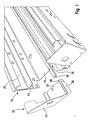
- the frame spar shown in Fig. 1 comprises a made of a galvanized steel sheet Zargenelement 10 in the form of an angle profile, a sealing strip 18 and an attachable to the lower edge of the Zargenelements 10 plastic cap 30th
- the frame element 10 has an attachment leg 12 to be applied to the wall to be closed with the opening to be closed, a side leg 14 extending perpendicularly thereto and a sealing leg 16 extending parallel to the side leg 14 starting from the edge of the support leg 12 facing away from the side leg 14.
- the sealing strip 18 is attached to the abutment leg 12 facing away from the edge of the sealing leg 16.
- a serving to guide the Torblattiolo guide rail 20 is attached.
- the guide rail 20 may be bolted to the side legs 14, riveted or welded. In terms of production technology, a riveted joint is particularly easy.
- the plastic cap 30 comprises a planar abutment plate 31, from the edges of which a total of three wall elements 32, 34 and 36 extend vertically upwards.
- the wall member 32 overlaps the lower edge of the abutment leg 12, the wall member 34, the lower edge of the side leg 14 and Furthermore, the plastic cap 30 in the region of the wall member 36 comprises a vertical fastening web 38, which is received in the mounted state shown in Fig. 2 in a groove formed in the sealing strip 18.
- Fig. 3 has the externally visible wall member 36, as well as the wall member 32 of the plastic cap 30, a height which corresponds substantially to the height of a attached to the lower edge of the door leaf 100 sealing member 110. Furthermore, the plastic cap 30 is made in the same color as the sealing element 110.
- a lower edge of the abutment leg 12 is offset with respect to the bottom edge of the side leg 14 such that in the mounted state, the vertical distance between the lower edge of the abutment leg 12 and the bottom is greater than the vertical distance between the lower edge of the side leg 14 and the floor.
Abstract
Description
Die Erfindung betrifft ein Tor, insbesondere Garagentor, mit einem Torblatt, das zwischen einer Öffnungsstellung und einer Schließstellung, in der es etwa in einer Vertikalebene angeordnet ist, bewegbar ist, und zwei im Bereich der seitlichen Ränder der mit dem Torblatt zu verschließenden Öffnung feststehend angeordneten und sich in der Torblatt-Schließstellung ausgehend von dem Boden der Öffnung im wesentlichen über die gesamte Torblatthöhe erstreckenden Zargenholmen sowie einem Zargenholm für ein derartiges Tor.The invention relates to a gate, in particular garage door, with a door leaf, which is movable between an open position and a closed position in which it is arranged approximately in a vertical plane, and two fixedly arranged in the region of the lateral edges of the opening to be closed with the door leaf and extending in the Torblatt-closed position starting from the bottom of the opening substantially over the entire Torblatt height extending Zargenholmen and a Zargenholm for such a goal.
Bei herkömmlichen Toren ist das Torblatt in der Schließstellung zwischen seitlichen Zargenholmen angeordnet. Dabei bilden die Zargenholme in der Torblatt-Schließstellung den Übergang zwischen der die zu verschließende Öffnung aufweisenden Wand und dem Torblatt. Die Zargenholme können in Form von Winkelprofilen mit einem an die die Öffnung aufweisende Wand anlegbaren Anlageschenkel und einem sich in einer Horizontalschnittebene senkrecht dazu erstreckenden Seitenschenkel ausgeführt sein. Dabei kann an der der zu verschließenden Öffnung zugewandten Begrenzungsfläche des Seitenschenkels eine zur Führung der Torblattbewegung zwischen der Öffnungsstellung und der Schließstellung dienende Führungsschiene angeordnet sein. Ferner kann an dem dem Seitenschenkel abgewandten Rand des Anlageschenkels ein Dichtungsschenkel angeordnet sein, der sich etwa parallel zum Seitenschenkel erstreckt und an seinem der Wand abgewandten Rand mit einem Dichtungsstreifen ausgestattet ist, welcher in der Torblatt-Schließstellung, zum Erhalt eines dichten Abschlusses der Öffnung, an der äußeren Begrenzungsfläche des Torblatts anliegt.In conventional gates, the door leaf is arranged in the closed position between lateral frame members. The Zargenholme in the door leaf closed position form the transition between the opening to be closed having wall and the door leaf. The Zargenholme can be designed in the form of angle profiles with an attachable to the wall having the opening and a leg extending in a horizontal section plane perpendicular thereto side legs. In this case, a guide rail for guiding the door leaf movement between the open position and the closed position may be arranged on the boundary surface of the side limb facing the opening to be closed. Furthermore, on the side leg remote from the edge of the abutment leg a sealing leg may be arranged which extends approximately parallel to the side leg and is provided at its wall-facing edge with a sealing strip, which in the door leaf closed position, to obtain a tight completion of the opening, on the outer boundary surface of the door leaf is applied.
Sektionaltore der gerade beschriebenen Art, bei denen die Torblattbewegung zwischen der Schließstellung und der Öffnungsstellung mit Hilfe von an den Seitenschenkeln der Zargenholme befestigten Führungsschienen geführt wird, sind beispielsweise in der
Die Zargenholme von Toren der vorstehend beschriebenen Art sind üblicherweise aus verzinktem Stahlblech hergestellt. Dabei erfolgt die Herstellung üblicherweise ausgehend von einem Band aus verzinktem Stahlblech durch Abkanten bzw. Umformen dieses Bandes in die gewünschte Form und abschließendes Zuschneiden bzw. Ablängen der so erhaltenen Zwischenprodukte auf die gewünschte Zargenholmlänge.The Zargenholme of gates of the type described above are usually made of galvanized sheet steel. The preparation is usually carried out starting from a strip of galvanized steel sheet by folding or forming this band in the desired shape and final cutting or cutting to length of the resulting intermediate products to the desired Zargenholmlänge.
Bei der Montage der gerade beschriebenen Tore werden die Zargenholme auf dem Boden des mit dem Tor zu verschließenden Raums aufstehend an die die Öffnung aufweisende Wand und/oder eine senkrecht dazu verlaufende Wand des mit dem Tor zu verschließenden Raums angeschlagen. Verursacht durch die bei der Herstellung der Zargenholme entstandenen scharfen Schnittkanten, kann es dabei zu Beschädigungen des Bodens und/oder des Zargenholms selbst kommen. Ferner wird beim Langzeitbetrieb der bekannten Garagentore, trotz Verwendung von verzinktem Stahlblech als Material für die Zargenholme, in vielen Fällen eine Rostbildung im Bereich des unteren Randes der Zargenholme beobachtet. Zur Beseitigung dieser Mängel wurde bereits vorgeschlagen, im Bereich der unteren Ränder der Zargenholme Zargenfüße aus verzinktem Material anzubringen. Dabei wurden zunächst Zargenfüße als separate Bauteile an den unteren Rand der Zargenholme angebracht, insbesondere geschweißt. Dieses Herstellungsverfahren hat sich allerdings als wenig praktikabel erwiesen, weil es mit einem besonders hohen Aufwand im Zusammenhang mit der Anbringung der Zargenfüße an den Zargenholmen verbunden ist.During assembly of the gates just described the Zargenholme be struck on the bottom of the door to be closed with the space upstanding wall having the opening and / or a perpendicular thereto wall of the door to be closed space. Caused by the sharp edges produced during the production of the frame spars, damage to the floor and / or the frame spar itself can occur. Further, in the long-term operation of the known garage doors, despite the use of galvanized steel sheet as the material for the Zargenholme, in many cases rust formation in the region of the lower edge of the Zargenholme observed. To eliminate these deficiencies has already been proposed to install Zargenfüße of galvanized material in the area of the lower edges of the Zargenholme. Here, first Zargenfüße were attached as separate components to the lower edge of the Zargenholme, in particular welded. However, this manufacturing method has proved to be less practical, because it is associated with a particularly high cost in connection with the attachment of the Zargenfüße to the Zargenholmen.
Angesichts dieses Mangels wurde vorgeschlagen, die Zargenfüße durch Abkanten eines unteren Randes eines der Schenkel der Zargenholme auszuführen. Dieses Verfahren hat sich als praktikabel und für eine Massenproduktion tauglich erwiesen.In view of this defect, it has been proposed to carry out the frame feet by folding a lower edge of one of the legs of the frame beams. This method has proven to be practical and suitable for mass production.
Allerdings können die beim Dauereinsatz der eingangs beschriebenen herkömmlichen Zargenholme erläuterten Probleme bzgl. der Beschädigung der Zargenholme weder unter Verwendung von Zargenfüßen in Form separater Bauelemente noch bei Einsatz von durch Umbiegen eines Schenkels der Zargen erhaltenen Zargenfüßen vollständig beseitigt werden.However, the problems explained in the continuous use of the above-described conventional Zargenholme respect. Damage to the Zargenholme can be completely eliminated either using Zargenfüßen in the form of separate components or when using obtained by bending a leg of the frames Zargenfüßen.
Angesichts der vorstehend beschriebenen Probleme im Stand der Technik liegt der Erfindung die Aufgabe zugrunde, Tore der eingangs beschriebenen Art bereitzustellen, mit denen Beschädigungen im Bereich der Zargenholme zuverlässig verhindert werden können, und Zargenholme für derartige Tore anzugeben.In view of the above-described problems in the prior art, the present invention seeks to provide gates of the type described above, with which damage in the Zargenholme can be reliably prevented, and specify Zargenholme for such goals.
Erfindungsgemäß wird diese Aufgabe durch eine Weiterbildung der bekannten Tore gelöst, die im wesentlichen dadurch gekennzeichnet ist, daß ein am Boden anliegender Fußbereich mindestens eines Zargenholms aus Kunststoff besteht.According to the invention this object is achieved by a development of the known goals, which is essentially characterized in that a resting on the floor foot area of at least one Zargenholms consists of plastic.
Diese Erfindung geht auf die Erkenntnis zurück, daß korrosionsbedingte Beschädigungen der Zargenholme bekannter Tore bereits dann zuverlässig verhindert werden können, wenn nur ein Fußbereich der ansonsten aus verzinktem Stahlblech bestehenden Zargenholme aus einem korrosionsresistenten Material besteht. Dabei kann die im allgemeinen erforderliche Stabilität der Zargenholme sichergestellt werden, wenn oberhalb des Fußbereichs ein im wesentlichen aus Metall, insbesondere verzinktem Stahl, bestehendes Zargenelement angeordnet ist.This invention is based on the finding that corrosion-related damage to the frame members of known goals can already be reliably prevented even if only one foot region of the otherwise made of galvanized sheet steel Zargenholme consists of a corrosion-resistant material. In this case, the generally required stability of the Zargenholme can be ensured if above the foot of a substantially metal, in particular galvanized steel, existing Zargenelement is arranged.
Produktionstechnisch hat es sich als besonders günstig erwiesen, wenn der Fußbereich eine an dem dem Boden zugewandten Rand des Zargenelements aus verzinktem Stahlblech anlegbare bzw. darauf aufsteckbare und diesen Rand vorzugsweise teilweise überlappende Kunststoffkappe aufweist, weil bei dieser Konstruktion keine aufwendigen Befestigungstechniken, wie etwa Schweißen, zur Herstellung der Zargenholme benötigt werden. Vielmehr reicht es aus, wenn die separat gefertigten Bauelemente (Kunststoffkappe und Zargenelement) einfach zusammengesteckt werden.In terms of production technology, it has proved to be particularly favorable if the foot region has a plastic cap which can be applied to the bottom edge of the frame element made of galvanized sheet steel and which can be attached to it and preferably partially overlaps this edge, because in this construction no complicated fastening techniques, such as welding, needed for the production of Zargenholme. Rather, it is sufficient if the separately manufactured components (plastic cap and Zargenelement) are simply plugged together.
Ein besonders zuverlässiger Korrosionsschutz der Zargenholme erfindungsgemäßer Tore kann erreicht werden, wenn die Kunststoffkappe mindestens eine Auflagefläche für den unteren Rand des beispielsweise aus verzinktem Stahl hergestellten Zargenelements aufweist und der vertikale Abstand zwischen einer dem Boden zugewandten Begrenzungsfläche der Kunststoffkappe und der Auflagefläche 10 mm oder mehr, vorzugsweise 15 mm oder mehr, insbesondere 20 mm oder mehr, beträgt. Auf diese Weise wird erreicht, daß die unteren Schnittkanten der metallischen Zargenelemente einen Abstand von 10 mm oder mehr vom Boden aufweisen und damit von Regenwasser, Schmutz oder anderen korrosionsfördernden Substanzen kaum noch erreichbar sind.A particularly reliable corrosion protection of the Zargenholme inventive gates can be achieved if the plastic cap has at least one support surface for the lower edge of the example made of galvanized steel Zargenelements and the vertical distance between a bottom facing the boundary surface of the plastic cap and the
Zum Erhalt der benötigten Stabilität der Gesamtkonstruktion, im besonderen im Bereich der üblicherweise zur Anbringung von Führungsschienen vorgesehenen Seitenschenkel metallischer Zargenelemente, hat es sich als zweckmäßig erwiesen, wenn der vertikale Abstand zwischen der dem Boden zugewandten Begrenzungsfläche der Kunststoffkappe und der Auflagefläche für den unteren Rand des Zargenelements 100 mm oder weniger, insbesondere 70 mm oder weniger, aufweist.To obtain the required stability of the overall construction, in particular in the area of the side legs of metallic frame elements usually provided for the attachment of guide rails, it has proved expedient if the vertical distance between the boundary surface of the plastic cap facing the floor and the support surface for the lower edge of the
Wie vorstehend im Zusammenhang mit herkömmlichen Zargenholmen bereits erläutert, hat es sich im besonderen bei Sektionaltoren als zweckmäßig erwiesen, wenn das Zargenelement die Form eines Winkelprofils mit einem an die die Öffnung aufweisende Wand anlegbaren Anlageschenkel und einem in einer Horizontalschnittebene etwa senkrecht dazu verlaufenden Seitenschenkel zum Anbringen der Führungsschienen sowie vorzugsweise einen ausgehend von dem dem Seitenschenkel abgewandten Rand des Anlageschenkels sich etwa parallel zum Seitenschenkel erstreckenden Dichtungsschenkel aufweist.As already explained above in connection with conventional Zargenholmen, it has proven to be particularly useful in sectional doors when the Zargenelement the shape of an angle profile with an attachable to the wall opening leg and a in a horizontal section plane approximately perpendicular thereto side legs for mounting the guide rails and preferably a starting from the side leg facing away from the edge of the support leg has approximately parallel to the side leg extending sealing leg.
Im Sinne einer Vermeidung von Beschädigungen der Zargenholme erfindungsgemäßer Tore hat es sich als zweckmäßig erwiesen, wenn die Kunststoffkappe eine an den Boden anlegbare, im wesentlichen ebene Anlageplatte aufweist. Eine solche Kunststoffkappe kann besonders einfach auf den unteren Rand eines metallischen Zargenelements aufgesteckt werden, wenn sie mindestens ein von einem Rand der Anlageplatte ausgehendes, sich etwa senkrecht dazu erstreckendes und den unteren Rand mindestens eines Schenkels des Zargenelements vorzugsweise auf dessen Außenseite überlappendes Wandelement aufweist. Zweckmäßigerweise übergreift das Wandelement eine äußere Begrenzungsfläche des metallischen Zargenelements.In terms of avoiding damage to the Zargenholme inventive gates, it has proven to be expedient if the plastic cap has an attachable to the ground, substantially flat contact plate. Such a plastic cap can be attached in a particularly simple manner to the lower edge of a metallic frame element if it has at least one wall element extending from an edge of the contact plate and extending approximately perpendicularly thereto and preferably overlapping the lower edge of at least one leg of the frame element on its outer side. Conveniently, the wall element engages over an outer boundary surface of the metallic frame element.
Ebenso wie die Zargenholme herkömmlicher Tore kann auch der Zargenholm erfindungsgemäßer Tore einen in der Schließstellung an einer äußeren Begrenzungsfläche des Torblatts anliegenden und an dem Zargenelement, insbesondere dem dem Anlageschenkel abgewandten Rand des Dichtungsschenkels, befestigten Dichtungsstreifen aufweisen, wobei ein über den unteren Rand des Zargenelements hervorstehender unterer Endbereich des Dichtungsstreifens bei erfindungsgemäßen Toren vorzugsweise formschlüssig an der Kunststoffkappe befestigt ist. Dazu kann ein an der Kunststoffkappe (Dichtungsstreifen) ausgebildeter vertikaler Befestigungssteg in einer in dem Dichtungsstreifen (Kunststoffkappe) gebildeten Nut aufgenommen sein.As well as the Zargenholme conventional goals and the Zargenholm inventive gates may have a in the closed position on an outer boundary surface of the door leaf and on the Zargenelement, in particular the investment leg remote from the edge of the sealing leg, mounted sealing strip, with a projecting beyond the lower edge of the Zargenelements lower end portion of the weather strip in gates according to the invention is preferably attached positively to the plastic cap. For this purpose, a vertical fastening web formed on the plastic cap (sealing strip) can be accommodated in a groove formed in the sealing strip (plastic cap).
Bei herkömmlichen Toren ist an dem in der Schließstellung unteren Rand des Torblatts üblicherweise ein sich im wesentlichen über die gesamte Torblattbreite erstreckendes Dichtungselement angebracht. Zum Erhalt eines gefälligen äußeren Erscheinungsbildes erfindungsgemäßer Tore hat es sich als zweckmäßig erwiesen, wenn die Höhe eines von außen erkennbaren Wandelements der Kunststoffkappe, insbesondere eines den Dichtungsschenkel und/oder den Anlageschenkel des Zargenelements übergreifenden Wandelements der Kunststoffkappe, etwa der Höhe des am unteren Rand des Torblatts angebrachten Dichtungselements entspricht und farblich auf das Dichtungselement abgestimmt ist.In conventional gates, a sealing element extending essentially over the entire door leaf width is usually attached to the lower edge of the door leaf in the closed position. To obtain a pleasing appearance of gates according to the invention, it has proven to be expedient if the height of an externally visible wall element of the plastic cap, in particular a sealing leg and / or the plant leg of Zargenelements cross-wall element of the plastic cap, about the height of the lower edge of the Torblatts attached sealing element corresponds and is color matched to the sealing element.
Üblicherweise ist der an der die zu verschließende Öffnung aufweisenden Wand anliegende Anlageschenkel des metallischen Zargenelements Witterungseinflüssen besonders stark ausgesetzt. Aus diesem Grund hat es sich als zweckmäßig erwiesen, wenn ein unterer Rand dieses Anlageschenkels oberhalb des unteren Randes des zur Befestigung der Führungsschienen dienenden Seitenschenkels angeordnet ist, um so einerseits eine ausreichende Korrosionsbeständigkeit an den besonders gefährdeten Stellen des Zargenelements zu erreichen und andererseits eine ausreichend stabile Befestigung der Führungsschienen an dem Zargenelement sicherzustellen.Usually, at the wall to be closed opening having wall abutting plant leg of the metallic frame element weather conditions is particularly exposed. For this reason, it has proven to be expedient if a lower edge of this abutment limb is arranged above the lower edge of the serving for fastening the guide rails side leg, so as to achieve a sufficient corrosion resistance at the most vulnerable points of the Zargenelements and on the other hand, a sufficiently stable Ensure fastening of the guide rails to the frame element.
Wie der vorstehenden Erläuterung erfindungsgemäßer Tore zu entnehmen ist, ist ein zur Herstellung solcher Tore geeigneter erfindungsgemäßer Zargenholm im wesentlichen dadurch gekennzeichnet, daß er ein vorzugsweise als Winkelprofil ausgeführtes Zargenelement aus einem metallischen Material und eine auf den unteren Rand dieses Zargenelements aufgesteckte Kunststoffkappe aufweist.As can be seen from the above explanation of gates according to the invention, a gate spar according to the invention suitable for the manufacture of such gates is essentially characterized in that it comprises a frame element made of a metallic material preferably designed as an angle profile and a plastic cap attached to the bottom edge of this frame element.
Nachstehend wird die Erfindung unter Bezugnahme auf die Zeichnung, auf die hinsichtlich aller erfindungswesentlichen und in der Beschreibung nicht näher herausgestellten Einzelheiten ausdrücklich verwiesen wird, erläutert. In der Zeichnung zeigt:
- Fig. 1
- einen erfindungsgemäßen Zargenholm mit abgenommener Kunststoffkappe,
- Fig. 2
- einen erfindungsgemäßen Zargenholm mit auf den unteren Rand aufgesteckter Kunststoffkappe und
- Fig. 3
- ein erfindungsgemäßes Tor im Bereich der am unteren Rand des Torblatts angebrachten Bodendichtung.
- Fig. 1
- a Zargenholm invention with removed plastic cap,
- Fig. 2
- a Zargenholm invention with attached to the lower edge plastic cap and
- Fig. 3
- an inventive gate in the region of the attached at the bottom of the door leaf bottom seal.
Der in Fig. 1 dargestellte Zargenholm umfaßt ein aus einem verzinkten Stahlblech hergestelltes Zargenelement 10 in Form eines Winkelprofils, einen Dichtungsstreifen 18 sowie eine auf den unteren Rand des Zargenelements 10 aufsteckbare Kunststoffkappe 30.The frame spar shown in Fig. 1 comprises a made of a galvanized
Das Zargenelement 10 weist einen an die die mit dem Tor zu verschließende Öffnung aufweisende Wand anzulegenden Anlageschenkel 12, einen sich senkrecht dazu erstreckenden Seitenschenkel 14 und einen sich ausgehend von dem dem Seitenschenkel 14 abgewandten Rand des Anlageschenkels 12 parallel zum Seitenschenkel 14 erstrekkenden Dichtungsschenkel 16 auf.The
Der Dichtungsstreifen 18 ist an dem dem Anlageschenkel 12 abgewandten Rand des Dichtungsschenkels 16 angebracht. An der dem Dichtungsschenkel 16 zugewandten Begrenzungsfläche des Seitenschenkels 14 ist eine zur Führung der Torblattbewegung dienende Führungsschiene 20 befestigt. Die Führungsschiene 20 kann an den Seitenschenkel 14 angeschraubt, genietet oder verschweißt sein. Produktionstechnisch besonders einfach ist eine Nietverbindung.The
Die Kunststoffkappe 30 umfaßt eine ebene Anlageplatte 31, von deren Rändern sich insgesamt drei Wandelemente 32, 34 und 36 vertikal nach oben erstrecken. In dem in Fig. 2 dargestellten montierten Zustand überlappt das Wandelement 32 den unteren Rand des Anlageschenkels 12, das Wandelement 34 den unteren Rand des Seitenschenkels 14 und das Wandelement 36 den unteren Rand des Dichtungsschenkels 16. Ferner umfaßt die Kunststoffkappe 30 im Bereich des Wandelements 36 einen vertikalen Befestigungssteg 38, der in dem in Fig. 2 dargestellten montierten Zustand in einer im Dichtungsstreifen 18 gebildeten Nut aufgenommen ist.The
Wie besonders deutlich in Fig. 3 zu sehen ist, weist das von außen erkennbare Wandelement 36, ebenso wie das Wandelement 32 der Kunststoffkappe 30, eine Höhe auf, die im wesentlichen der Höhe eines am unteren Rand des Torblatts 100 befestigten Dichtungselements 110 entspricht. Ferner ist die Kunststoffkappe 30 in derselben Farbe ausgeführt wie das Dichtungselement 110.As can be seen particularly clearly in Fig. 3, has the externally
Wie in Fig. 1 erkennbar ist, ist ein unterer Rand des Anlageschenkels 12 derart bzgl. dem unteren Rand des Seitenschenkels 14 versetzt angeordnet, daß im montierten Zustand der vertikale Abstand zwischen dem unteren Rand des Anlageschenkels 12 und dem Boden größer ist als der vertikale Abstand zwischen dem unteren Rand des Seitenschenkels 14 und dem Boden.As can be seen in Fig. 1, a lower edge of the
Claims (12)
Priority Applications (1)
| Application Number | Priority Date | Filing Date | Title |
|---|---|---|---|
| PL06011684T PL1795683T3 (en) | 2005-08-16 | 2006-06-06 | Garage door and its frame |
Applications Claiming Priority (1)
| Application Number | Priority Date | Filing Date | Title |
|---|---|---|---|
| DE102005038693A DE102005038693A1 (en) | 2005-08-16 | 2005-08-16 | Door e.g. garage door, has two edge strips, fixedly arranged in area of lateral edges of opening, having base area that are made of plastic and provided adjacent to base, where edge unit made of galvanized steel is arranged over base area |
Publications (3)
| Publication Number | Publication Date |
|---|---|
| EP1795683A2 true EP1795683A2 (en) | 2007-06-13 |
| EP1795683A3 EP1795683A3 (en) | 2010-03-03 |
| EP1795683B1 EP1795683B1 (en) | 2011-08-17 |
Family
ID=37697234
Family Applications (1)
| Application Number | Title | Priority Date | Filing Date |
|---|---|---|---|
| EP06011684A Active EP1795683B1 (en) | 2005-08-16 | 2006-06-06 | Garage door and its frame |
Country Status (6)
| Country | Link |
|---|---|
| EP (1) | EP1795683B1 (en) |
| AT (1) | ATE520854T1 (en) |
| DE (1) | DE102005038693A1 (en) |
| DK (1) | DK1795683T3 (en) |
| ES (1) | ES2284430T3 (en) |
| PL (1) | PL1795683T3 (en) |
Cited By (1)
| Publication number | Priority date | Publication date | Assignee | Title |
|---|---|---|---|---|
| DE102011000106B3 (en) * | 2011-01-12 | 2012-05-10 | Novoferm Gmbh | Torzarge, in particular for sectional doors and overhead doors |
Families Citing this family (3)
| Publication number | Priority date | Publication date | Assignee | Title |
|---|---|---|---|---|
| DE102010060930B3 (en) * | 2010-12-01 | 2012-03-15 | Novoferm Gmbh | Frame side part for sectional doors |
| DE102016009984A1 (en) | 2016-08-17 | 2018-02-22 | Hörmann KG Brockhagen | Tor and Zargenholm for it |
| DE102018118766A1 (en) | 2018-08-02 | 2020-02-06 | Hörmann KG Brockhagen | goal |
Citations (1)
| Publication number | Priority date | Publication date | Assignee | Title |
|---|---|---|---|---|
| EP0976904A1 (en) | 1998-07-31 | 2000-02-02 | Hörmann KG Brockhagen | Device for closing a wall opening |
Family Cites Families (5)
| Publication number | Priority date | Publication date | Assignee | Title |
|---|---|---|---|---|
| DE7320846U (en) * | 1973-10-11 | Hoermann Kg | Gate for garages | |
| GB2112437B (en) * | 1981-11-12 | 1985-09-11 | Rothervale Joinery Limited | Door frame with adjustable jambs |
| DE3422568C2 (en) * | 1983-10-14 | 1986-01-02 | Helmut 4407 Emsdetten Wedi | Sound-absorbing casing for a door frame base |
| US6161343A (en) * | 1997-10-17 | 2000-12-19 | Young; Robert H. | Wood rot preventing wood casing end grain moisture barrier assembly and method |
| DE102004010486B4 (en) * | 2004-03-04 | 2015-10-01 | Novoferm Gmbh | Gate for garages and halls |
-
2005
- 2005-08-16 DE DE102005038693A patent/DE102005038693A1/en not_active Ceased
-
2006
- 2006-06-06 EP EP06011684A patent/EP1795683B1/en active Active
- 2006-06-06 ES ES06011684T patent/ES2284430T3/en active Active
- 2006-06-06 PL PL06011684T patent/PL1795683T3/en unknown
- 2006-06-06 AT AT06011684T patent/ATE520854T1/en active
- 2006-06-06 DK DK06011684.5T patent/DK1795683T3/en active
Patent Citations (1)
| Publication number | Priority date | Publication date | Assignee | Title |
|---|---|---|---|---|
| EP0976904A1 (en) | 1998-07-31 | 2000-02-02 | Hörmann KG Brockhagen | Device for closing a wall opening |
Cited By (3)
| Publication number | Priority date | Publication date | Assignee | Title |
|---|---|---|---|---|
| DE102011000106B3 (en) * | 2011-01-12 | 2012-05-10 | Novoferm Gmbh | Torzarge, in particular for sectional doors and overhead doors |
| EP2476850A2 (en) | 2011-01-12 | 2012-07-18 | Novoferm GmbH | Door frame, in particular for sectional doors and overhead doors |
| EP2476850A3 (en) * | 2011-01-12 | 2014-10-29 | Novoferm GmbH | Door frame, in particular for sectional doors and overhead doors |
Also Published As
| Publication number | Publication date |
|---|---|
| PL1795683T3 (en) | 2012-01-31 |
| ES2284430T1 (en) | 2007-11-16 |
| DE102005038693A1 (en) | 2007-02-22 |
| DK1795683T3 (en) | 2011-10-31 |
| ES2284430T3 (en) | 2011-11-22 |
| EP1795683A3 (en) | 2010-03-03 |
| ATE520854T1 (en) | 2011-09-15 |
| EP1795683B1 (en) | 2011-08-17 |
Similar Documents
| Publication | Publication Date | Title |
|---|---|---|
| DE2338879A1 (en) | RAILING ELEMENT | |
| DE19634391C5 (en) | Floor anchoring for wings of a movable sliding wall made of insulating glass | |
| DE2313425A1 (en) | FLANGE CONNECTIONS FOR MUTUAL FASTENING OF MORE RECTANGULAR CHANNEL SECTIONS MADE OF SHEET METAL, ESPECIALLY FOR HIGH-PRESSURE VENTILATION SYSTEMS | |
| DE2635480A1 (en) | SLIDING WINDOWS WITH WEATHERPROOF SEAL | |
| EP1795683A2 (en) | Garage door and its frame | |
| DE19745750C5 (en) | Fighter connector for window and door frames | |
| AT522642B1 (en) | Kit for building a fence | |
| EP1978171B1 (en) | Elemented mullion and transom facade | |
| DE102005005745C5 (en) | Profile plate for covering a building roof and building roof | |
| AT501334B1 (en) | FRAME CONSTRUCTION | |
| EP1927715A2 (en) | Profile for window sash or door leaf | |
| DE8325105U1 (en) | SWIVEL FITTING FOR WINDOW | |
| EP1580394B1 (en) | Rain protection profile without end caps | |
| DE19832379C2 (en) | Sunroof for a motor vehicle | |
| DE2522112A1 (en) | Additional window frame wall cavity cover - consists of two telescopically interfitting frames with outer one fixed to building | |
| DE10201203B4 (en) | Closed metallic frame as part of a vehicle body and method for its manufacture | |
| EP0477544B1 (en) | Filling piece for glazing beads | |
| EP3257413B1 (en) | Decorative and/or functional part for installation in a corner or a recess, for example, of an at least partly tiled room | |
| DE4117743C2 (en) | Board piece for window sills | |
| EP2017425A2 (en) | Blind frame with cover strip | |
| CH661083A5 (en) | ROOF WINDOW. | |
| DE102014103650A1 (en) | Method and profile system for the production of building windows, building doors | |
| DE4315644C2 (en) | Building window | |
| EP0918132A2 (en) | Automatic floor seal for a door | |
| DE102011000160A1 (en) | Transparent/translucent dome light for assembling at flat roof, has recess formed in profile of frame, and drive whose housing is inserted into recess in form-fit manner, where frame is pivotally supported relative to article frame |
Legal Events
| Date | Code | Title | Description |
|---|---|---|---|
| PUAI | Public reference made under article 153(3) epc to a published international application that has entered the european phase |
Free format text: ORIGINAL CODE: 0009012 |
|
| AK | Designated contracting states |
Kind code of ref document: A2 Designated state(s): AT BE BG CH CY CZ DE DK EE ES FI FR GB GR HU IE IS IT LI LT LU LV MC NL PL PT RO SE SI SK TR |
|
| AX | Request for extension of the european patent |
Extension state: AL BA HR MK YU |
|
| REG | Reference to a national code |
Ref country code: SE Ref legal event code: TRCL |
|
| EL | Fr: translation of claims filed | ||
| TCNL | Nl: translation of patent claims filed | ||
| PUAL | Search report despatched |
Free format text: ORIGINAL CODE: 0009013 |
|
| AK | Designated contracting states |
Kind code of ref document: A3 Designated state(s): AT BE BG CH CY CZ DE DK EE ES FI FR GB GR HU IE IS IT LI LT LU LV MC NL PL PT RO SE SI SK TR |
|
| AX | Request for extension of the european patent |
Extension state: AL BA HR MK RS |
|
| 17P | Request for examination filed |
Effective date: 20100715 |
|
| AKX | Designation fees paid |
Designated state(s): AT BE BG CH CY CZ DE DK EE ES FI FR GB GR HU IE IS IT LI LT LU LV MC NL PL PT RO SE SI SK TR |
|
| GRAP | Despatch of communication of intention to grant a patent |
Free format text: ORIGINAL CODE: EPIDOSNIGR1 |
|
| RIC1 | Information provided on ipc code assigned before grant |
Ipc: E05D 15/16 20060101AFI20110302BHEP |
|
| GRAS | Grant fee paid |
Free format text: ORIGINAL CODE: EPIDOSNIGR3 |
|
| GRAA | (expected) grant |
Free format text: ORIGINAL CODE: 0009210 |
|
| AK | Designated contracting states |
Kind code of ref document: B1 Designated state(s): AT BE BG CH CY CZ DE DK EE ES FI FR GB GR HU IE IS IT LI LT LU LV MC NL PL PT RO SE SI SK TR |
|
| REG | Reference to a national code |
Ref country code: GB Ref legal event code: FG4D Free format text: NOT ENGLISH |
|
| REG | Reference to a national code |
Ref country code: CH Ref legal event code: EP |
|
| REG | Reference to a national code |
Ref country code: SE Ref legal event code: TRGR |
|
| REG | Reference to a national code |
Ref country code: IE Ref legal event code: FG4D Free format text: LANGUAGE OF EP DOCUMENT: GERMAN |
|
| REG | Reference to a national code |
Ref country code: DE Ref legal event code: R096 Ref document number: 502006010020 Country of ref document: DE Effective date: 20111020 |
|
| REG | Reference to a national code |
Ref country code: DK Ref legal event code: T3 |
|
| REG | Reference to a national code |
Ref country code: ES Ref legal event code: FG2A Ref document number: 2284430 Country of ref document: ES Kind code of ref document: T3 Effective date: 20111122 |
|
| REG | Reference to a national code |
Ref country code: NL Ref legal event code: T3 |
|
| PG25 | Lapsed in a contracting state [announced via postgrant information from national office to epo] |
Ref country code: IS Free format text: LAPSE BECAUSE OF FAILURE TO SUBMIT A TRANSLATION OF THE DESCRIPTION OR TO PAY THE FEE WITHIN THE PRESCRIBED TIME-LIMIT Effective date: 20111217 Ref country code: PT Free format text: LAPSE BECAUSE OF FAILURE TO SUBMIT A TRANSLATION OF THE DESCRIPTION OR TO PAY THE FEE WITHIN THE PRESCRIBED TIME-LIMIT Effective date: 20111219 Ref country code: FI Free format text: LAPSE BECAUSE OF FAILURE TO SUBMIT A TRANSLATION OF THE DESCRIPTION OR TO PAY THE FEE WITHIN THE PRESCRIBED TIME-LIMIT Effective date: 20110817 |
|
| REG | Reference to a national code |
Ref country code: PL Ref legal event code: T3 |
|
| PG25 | Lapsed in a contracting state [announced via postgrant information from national office to epo] |
Ref country code: SI Free format text: LAPSE BECAUSE OF FAILURE TO SUBMIT A TRANSLATION OF THE DESCRIPTION OR TO PAY THE FEE WITHIN THE PRESCRIBED TIME-LIMIT Effective date: 20110817 Ref country code: LV Free format text: LAPSE BECAUSE OF FAILURE TO SUBMIT A TRANSLATION OF THE DESCRIPTION OR TO PAY THE FEE WITHIN THE PRESCRIBED TIME-LIMIT Effective date: 20110817 Ref country code: GR Free format text: LAPSE BECAUSE OF FAILURE TO SUBMIT A TRANSLATION OF THE DESCRIPTION OR TO PAY THE FEE WITHIN THE PRESCRIBED TIME-LIMIT Effective date: 20111118 Ref country code: CY Free format text: LAPSE BECAUSE OF FAILURE TO SUBMIT A TRANSLATION OF THE DESCRIPTION OR TO PAY THE FEE WITHIN THE PRESCRIBED TIME-LIMIT Effective date: 20110817 |
|
| REG | Reference to a national code |
Ref country code: IE Ref legal event code: FD4D |
|
| PG25 | Lapsed in a contracting state [announced via postgrant information from national office to epo] |
Ref country code: IE Free format text: LAPSE BECAUSE OF FAILURE TO SUBMIT A TRANSLATION OF THE DESCRIPTION OR TO PAY THE FEE WITHIN THE PRESCRIBED TIME-LIMIT Effective date: 20110817 Ref country code: SK Free format text: LAPSE BECAUSE OF FAILURE TO SUBMIT A TRANSLATION OF THE DESCRIPTION OR TO PAY THE FEE WITHIN THE PRESCRIBED TIME-LIMIT Effective date: 20110817 |
|
| PG25 | Lapsed in a contracting state [announced via postgrant information from national office to epo] |
Ref country code: EE Free format text: LAPSE BECAUSE OF FAILURE TO SUBMIT A TRANSLATION OF THE DESCRIPTION OR TO PAY THE FEE WITHIN THE PRESCRIBED TIME-LIMIT Effective date: 20110817 Ref country code: RO Free format text: LAPSE BECAUSE OF FAILURE TO SUBMIT A TRANSLATION OF THE DESCRIPTION OR TO PAY THE FEE WITHIN THE PRESCRIBED TIME-LIMIT Effective date: 20110817 |
|
| PLBI | Opposition filed |
Free format text: ORIGINAL CODE: 0009260 |
|
| PLAX | Notice of opposition and request to file observation + time limit sent |
Free format text: ORIGINAL CODE: EPIDOSNOBS2 |
|
| 26 | Opposition filed |
Opponent name: NOVOFERM GMBH Effective date: 20120516 |
|
| PLBB | Reply of patent proprietor to notice(s) of opposition received |
Free format text: ORIGINAL CODE: EPIDOSNOBS3 |
|
| REG | Reference to a national code |
Ref country code: DE Ref legal event code: R026 Ref document number: 502006010020 Country of ref document: DE Effective date: 20120516 |
|
| BERE | Be: lapsed |
Owner name: HORMANN K.G. BROCKHAGEN Effective date: 20120630 |
|
| PG25 | Lapsed in a contracting state [announced via postgrant information from national office to epo] |
Ref country code: MC Free format text: LAPSE BECAUSE OF NON-PAYMENT OF DUE FEES Effective date: 20120630 |
|
| REG | Reference to a national code |
Ref country code: CH Ref legal event code: PL |
|
| REG | Reference to a national code |
Ref country code: CH Ref legal event code: PL |
|
| GBPC | Gb: european patent ceased through non-payment of renewal fee |
Effective date: 20120606 |
|
| PG25 | Lapsed in a contracting state [announced via postgrant information from national office to epo] |
Ref country code: LI Free format text: LAPSE BECAUSE OF NON-PAYMENT OF DUE FEES Effective date: 20120630 Ref country code: CH Free format text: LAPSE BECAUSE OF NON-PAYMENT OF DUE FEES Effective date: 20120630 Ref country code: BE Free format text: LAPSE BECAUSE OF NON-PAYMENT OF DUE FEES Effective date: 20120630 Ref country code: GB Free format text: LAPSE BECAUSE OF NON-PAYMENT OF DUE FEES Effective date: 20120606 |
|
| PG25 | Lapsed in a contracting state [announced via postgrant information from national office to epo] |
Ref country code: BG Free format text: LAPSE BECAUSE OF FAILURE TO SUBMIT A TRANSLATION OF THE DESCRIPTION OR TO PAY THE FEE WITHIN THE PRESCRIBED TIME-LIMIT Effective date: 20111117 |
|
| PG25 | Lapsed in a contracting state [announced via postgrant information from national office to epo] |
Ref country code: TR Free format text: LAPSE BECAUSE OF FAILURE TO SUBMIT A TRANSLATION OF THE DESCRIPTION OR TO PAY THE FEE WITHIN THE PRESCRIBED TIME-LIMIT Effective date: 20110817 |
|
| PG25 | Lapsed in a contracting state [announced via postgrant information from national office to epo] |
Ref country code: LU Free format text: LAPSE BECAUSE OF NON-PAYMENT OF DUE FEES Effective date: 20120606 |
|
| PG25 | Lapsed in a contracting state [announced via postgrant information from national office to epo] |
Ref country code: HU Free format text: LAPSE BECAUSE OF FAILURE TO SUBMIT A TRANSLATION OF THE DESCRIPTION OR TO PAY THE FEE WITHIN THE PRESCRIBED TIME-LIMIT Effective date: 20060606 |
|
| PLCK | Communication despatched that opposition was rejected |
Free format text: ORIGINAL CODE: EPIDOSNREJ1 |
|
| APBM | Appeal reference recorded |
Free format text: ORIGINAL CODE: EPIDOSNREFNO |
|
| APBP | Date of receipt of notice of appeal recorded |
Free format text: ORIGINAL CODE: EPIDOSNNOA2O |
|
| APAH | Appeal reference modified |
Free format text: ORIGINAL CODE: EPIDOSCREFNO |
|
| APBQ | Date of receipt of statement of grounds of appeal recorded |
Free format text: ORIGINAL CODE: EPIDOSNNOA3O |
|
| REG | Reference to a national code |
Ref country code: FR Ref legal event code: PLFP Year of fee payment: 11 |
|
| PLAB | Opposition data, opponent's data or that of the opponent's representative modified |
Free format text: ORIGINAL CODE: 0009299OPPO |
|
| R26 | Opposition filed (corrected) |
Opponent name: NOVOFERM GMBH Effective date: 20120516 |
|
| REG | Reference to a national code |
Ref country code: FR Ref legal event code: PLFP Year of fee payment: 12 |
|
| REG | Reference to a national code |
Ref country code: DE Ref legal event code: R082 Ref document number: 502006010020 Country of ref document: DE Representative=s name: BOEHMERT & BOEHMERT ANWALTSPARTNERSCHAFT MBB -, DE |
|
| REG | Reference to a national code |
Ref country code: FR Ref legal event code: PLFP Year of fee payment: 13 |
|
| REG | Reference to a national code |
Ref country code: DE Ref legal event code: R100 Ref document number: 502006010020 Country of ref document: DE |
|
| APBU | Appeal procedure closed |
Free format text: ORIGINAL CODE: EPIDOSNNOA9O |
|
| PLAB | Opposition data, opponent's data or that of the opponent's representative modified |
Free format text: ORIGINAL CODE: 0009299OPPO |
|
| PLBN | Opposition rejected |
Free format text: ORIGINAL CODE: 0009273 |
|
| STAA | Information on the status of an ep patent application or granted ep patent |
Free format text: STATUS: OPPOSITION REJECTED |
|
| R26 | Opposition filed (corrected) |
Opponent name: NOVOFERM GMBH Effective date: 20120516 |
|
| 27O | Opposition rejected |
Effective date: 20190123 |
|
| PGFP | Annual fee paid to national office [announced via postgrant information from national office to epo] |
Ref country code: AT Payment date: 20190618 Year of fee payment: 14 |
|
| REG | Reference to a national code |
Ref country code: AT Ref legal event code: MM01 Ref document number: 520854 Country of ref document: AT Kind code of ref document: T Effective date: 20200606 |
|
| PG25 | Lapsed in a contracting state [announced via postgrant information from national office to epo] |
Ref country code: AT Free format text: LAPSE BECAUSE OF NON-PAYMENT OF DUE FEES Effective date: 20200606 |
|
| PGFP | Annual fee paid to national office [announced via postgrant information from national office to epo] |
Ref country code: LT Payment date: 20220525 Year of fee payment: 17 Ref country code: DK Payment date: 20220623 Year of fee payment: 17 |
|
| PGFP | Annual fee paid to national office [announced via postgrant information from national office to epo] |
Ref country code: IT Payment date: 20220630 Year of fee payment: 17 |
|
| P01 | Opt-out of the competence of the unified patent court (upc) registered |
Effective date: 20230316 |
|
| PGFP | Annual fee paid to national office [announced via postgrant information from national office to epo] |
Ref country code: NL Payment date: 20230620 Year of fee payment: 18 Ref country code: FR Payment date: 20230619 Year of fee payment: 18 Ref country code: DE Payment date: 20230620 Year of fee payment: 18 Ref country code: CZ Payment date: 20230525 Year of fee payment: 18 |
|
| PGFP | Annual fee paid to national office [announced via postgrant information from national office to epo] |
Ref country code: SE Payment date: 20230622 Year of fee payment: 18 Ref country code: PL Payment date: 20230525 Year of fee payment: 18 |
|
| PGFP | Annual fee paid to national office [announced via postgrant information from national office to epo] |
Ref country code: ES Payment date: 20230719 Year of fee payment: 18 |
|
| REG | Reference to a national code |
Ref country code: LT Ref legal event code: MM4D Effective date: 20230606 |
|
| REG | Reference to a national code |
Ref country code: DK Ref legal event code: EBP Effective date: 20230630 |
|
| PG25 | Lapsed in a contracting state [announced via postgrant information from national office to epo] |
Ref country code: LT Free format text: LAPSE BECAUSE OF NON-PAYMENT OF DUE FEES Effective date: 20230606 |