EP1795105B1 - Aspirateur - Google Patents
Aspirateur Download PDFInfo
- Publication number
- EP1795105B1 EP1795105B1 EP06256118A EP06256118A EP1795105B1 EP 1795105 B1 EP1795105 B1 EP 1795105B1 EP 06256118 A EP06256118 A EP 06256118A EP 06256118 A EP06256118 A EP 06256118A EP 1795105 B1 EP1795105 B1 EP 1795105B1
- Authority
- EP
- European Patent Office
- Prior art keywords
- handle
- vacuum cleaner
- carry
- elongate
- elongate handle
- Prior art date
- Legal status (The legal status is an assumption and is not a legal conclusion. Google has not performed a legal analysis and makes no representation as to the accuracy of the status listed.)
- Not-in-force
Links
- 239000000428 dust Substances 0.000 description 5
- 210000003141 lower extremity Anatomy 0.000 description 3
- 210000001364 upper extremity Anatomy 0.000 description 3
- 238000004140 cleaning Methods 0.000 description 2
- 230000005484 gravity Effects 0.000 description 2
- 230000004048 modification Effects 0.000 description 2
- 238000012986 modification Methods 0.000 description 2
- 230000004913 activation Effects 0.000 description 1
- 239000012530 fluid Substances 0.000 description 1
- 230000000717 retained effect Effects 0.000 description 1
Images


Classifications
-
- A—HUMAN NECESSITIES
- A47—FURNITURE; DOMESTIC ARTICLES OR APPLIANCES; COFFEE MILLS; SPICE MILLS; SUCTION CLEANERS IN GENERAL
- A47L—DOMESTIC WASHING OR CLEANING; SUCTION CLEANERS IN GENERAL
- A47L9/00—Details or accessories of suction cleaners, e.g. mechanical means for controlling the suction or for effecting pulsating action; Storing devices specially adapted to suction cleaners or parts thereof; Carrying-vehicles specially adapted for suction cleaners
- A47L9/32—Handles
- A47L9/325—Handles for wheeled suction cleaners with steering handle
-
- A—HUMAN NECESSITIES
- A47—FURNITURE; DOMESTIC ARTICLES OR APPLIANCES; COFFEE MILLS; SPICE MILLS; SUCTION CLEANERS IN GENERAL
- A47L—DOMESTIC WASHING OR CLEANING; SUCTION CLEANERS IN GENERAL
- A47L9/00—Details or accessories of suction cleaners, e.g. mechanical means for controlling the suction or for effecting pulsating action; Storing devices specially adapted to suction cleaners or parts thereof; Carrying-vehicles specially adapted for suction cleaners
- A47L9/32—Handles
- A47L9/322—Handles for hand-supported suction cleaners
Definitions
- the present invention relates to a vacuum cleaner.
- So-called stick vacuum cleaners are well known. They have an elongate structure comprising a floor-engaging nozzle or tool, a housing enclosing a separating device, typically a filter bag and a motor-fan unit, and an elongate handle with which the cleaner is propelled and guided over the surface being cleaned.
- Stick cleaners can be excessively long, some examples being as long as 150cm, which can render handling and storage of the cleaner difficult.
- EP 1033101 discloses an electric cleaner appliance with a foldaway handle which can be fully extended or stowed away.
- the electric cleaner also has a laterally placed handle situated substantially at the centre of gravity of the appliance.
- the laterally placed handle is described as being more convenient to hold the appliance when the foldaway handle is stowed.
- the laterally placed handle is situated substantially at the centre of gravity of the appliance and is fixed in position it is inconvenient for picking up and moving the appliance when the foldaway handle is stowed.
- WO2004/096000 described a floor cleaning apparatus which includes a nozzle assembly and a canister assembly connected to the nozzle assembly.
- a suction generator and a dirt collection vessel are carried by the nozzle assembly or the canister assembly.
- the vacuum cleaner further includes a control handle which is displaceable between operating and storage position.
- An object of the present invention is to provide a vacuum cleaner with improved ergonomics for storing and carrying the cleaner, particularly for transporting the cleaner to and from its storage location.
- the present invention relates to a vacuum cleaner according to claim 1.
- the present invention provides a vacuum cleaner with a carry handle that becomes accessible for use when the elongate handle is moved from the extended to the stowed position so that the carry handle is convenient for picking up and moving the vacuum cleaner when the elongate handle is stowed.
- the carry handle preferably moves from a latent position to an access position as the elongate handle is moved from the extended position to the stowed position.
- the carry handle is advantageously accessible and ready for use without requiring any further action from the user.
- the carry handle substantially conforms with the shape of the outer surface of the cleaner body and elongate handle in an area adjacent to the carry handle so the vacuum cleaner maintains a streamlined form and manoeuverability.
- the elongate handle preferably folds from the extended to the stowed position.
- the elongate handle is pivotally mounted and may be pivotally connected to the cleaner body.
- the carry handle is preferably pivotally mounted.
- the carry handle is advantageously moveable in position allowing the handle to be grasped from various angles increasing the ease with which the pivotally mounted carry handle can be used when the elongate handle is in its stowed position.
- the carry handle preferably has a common pivotal axis with the elongate handle.
- the carry handle is preferably prevented from moving from its access position to the latent position when the elongate handle is in its stowed position so that the movement of the cleaner body relative to the carry handle is limited to improve control over the vacuum cleaner when it is being carried by the carry handle.
- the carry handle can preferably be moved from its access position to a second latent position when the elongate handle is in its stowed position to reduce the height of the vacuum cleaner when the elongate handle is in its stowed position and the vacuum cleaner is e.g. being stored.
- the space required for storing the vacuum cleaner is advantageously reduced.
- the carry handle is mechanically engaged with the elongate handle.
- Advantageously movement of the elongate handle can be effectively transmitted to the carry handle.
- the carry handle has a protrusion which engages in a recess in the elongate handle such that as the elongate handle is pivoted between the extended position and the stowed position the protrusion is moved with the recess causing the carry handle to pivot from a latent to an access position.
- the connection between the elongate handle and the carry handle is a simple connection minimising moving parts.
- the carry handle is preferably substantially U-shaped so it can be easily gripped.
- the vacuum cleaner preferably comprises means to hold the elongate handle in its stowed position so the elongate handle can be secured in its stowed position and the cleaner can be easily transported or used when the elongate handle is stowed.
- the vacuum cleaner preferably further comprising a hand-grip portion spaced from the carry handle to aid in manoeuvring the vacuum cleaner when the elongate handle is stowed.
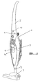
- Figure 1 shows a stick-type vacuum cleaner 1 having a cleaner body 3 and an elongate handle 5 (hereinafter referred to as "handle").
- the handle 5 is shown in its extended position in which it extends outwardly from the cleaner body 3.
- the cleaner body has an upper extremity to which the handle 5 is connected and a lower extremity at which is positioned a suction port 9.
- the cleaner body 3 is in fluid connection, via the suction port 9, with e.g. floor engaging nozzle unit 7.
- the cleaner body 3 houses means for effecting suction of air through the suction port, such as a motor/fan unit (not shown), and means for receiving air from the suction port and arranged to remove and collect dirt and dust from the air.
- the means arranged to remove and collect dirt and dust from the air may be a filter bag or other receptacle for dirt and dust.
- the cleaner body 3 and the handle 5 are disposed in a substantially end to end relationship with a substantially common axis.
- the cleaner body is also provided with a hand-grip portion 12 which extends over a recessed portion 14 into which the fingers can be inserted to grip the hand-grip portion 12.
- the motor/fan unit draws air and dirt/dust from the surface to which the cleaner is applied up through the suction nozzle via the suction port 9 to the means arranged to remove and collect dirt and dust from the air.
- the handle 5 is used to guide and propel the cleaner over the surface to be cleaned.
- the stick cleaner 1 has a carry handle 11 intermediate the handle 5 and cleaner body 3, which is disposed in a latent position when the handle is in the extended position shown in figure 1 .
- the carry handle 11 substantially conforms with the shape of the outer surface of cleaner body 3 and handle 5 in the area adjacent the carry handle 11.
- the carry handle 11 rests in contact with the upper end of cleaner body 3 and is positioned in a recess which extends around the outer surface of the upper end of cleaner body 3.
- the handle 5 is held in its first extended position by catch means in the form of a biassed lug 13 on the handle 5 which engages with a corresponding recess 15 in the body portion 3.
- the lug 13 can be moved horizontally against the bias e.g. by application of pressure to activation button 17 allowing it to be released from the recess 15.
- the handle 5 is pivotally connected to the cleaner body 3.
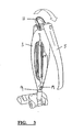
- Figure 3 shows the stick cleaner 1 as the handle 5 is pivoted from its extended position to the stowed position in which it is folded down substantially adjacent to the cleaner body 3.
- the carry handle 11 is deployed into an access position, extending from the upper extremity of the cleaner body, as the handle 5 pivots from its extended position to its stowed position.
- the carry handle 11 and handle 5 have a common pivotal axis.
- the handle 5 is held in place in its stowed position by engaging with catch means 19 at the lower extremity of the cleaner body 3, where the lower extremity is the end nearest the suction port 9.
- the handle may snap-fit into catch means 19.
- Figure 4 shows the handle 5 folded down in its stowed position with its axis substantially parallel to the axis of the cleaner body 3 and the carry handle 11 in its access position extending or projecting upwardly from the upper extremity of the cleaner body 3.
- Figure 5 shows the carry handle 11 being used to pick up and transport the stick cleaner 1 when the handle 5 is in its stowed position and the cleaner is not in use.
- Figure 6 shows how the carry handle 11 can also be used to support and guide the cleaner body 3 when the cleaner is in use with the handle 5 in its stowed position.
- the hand-grip portion 12 is further used to support and guide the cleaner body 3 when the handle 5 is in the stowed position.
- the suction port 9 of the cleaner body in this case is attached to an elongate crevice tool 21 suitable for e.g. cleaning upholstery or "hard to reach" areas of surfaces such as corners.
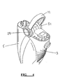
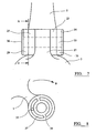
- Figure 7 illustrates the mechanism by which the carry handle 11 is deployed as handle 5 is moved from its extended position to its stowed position.
- Handle 5 has two spaced protruding portions 23,25, each having a central bore, disposed on its lower end, where the lower end is the end at which it is connected to the cleaner body.
- Cleaner body 3 has one protruding portion 27, also having a central bore, disposed on its upper end. The protruding portion 27 of cleaner body 3 is inserted between the protruding portions 23,25 of handle 5 so that the bores are in alignment.
- Carry handle 11 is substantially U-shaped and has a bore through the end portions 29,31 of the members making up the two sides of the U.
- the end portions 29,31 are disposed around the protruding portions 23,25 of handle 5 so that the bores are aligned and a spindle 33 is inserted through the bores of protruding portions 23,25,27 and end portions 29,31.
- the rotational axis of the pivot 33 thus passes through the free ends of the substantially U-shaped carry handle 11 through end portions 29,31.
- Spindle 33 is retained in the bores by retaining means 36,34 affixed to the outer edges of end portions 29,31.
- Figure 8 shows a cross-section along line A of figure 7 .
- the end portion 29 of carry handle 11 has a protrusion in the form of a peg 35 which extends inwardly towards the respective protruding portion 25 of the handle 5.
- the peg 35 fits into arcuate recess 37 in the protruding portion 25.
- the end wall 39 of the recess 37 engages and moves peg 35 thereby rotating carry handle end portion 29 as the portion 25 of the main handle 5 rotates.
- the carry handle is thereby moved from a latent position as shown in figures 1 and 2 to the access position shown in figures 4 , 5 and 6 .
- both end portions 29, 31 of carry handle 11 have protrusions which fit into recesses in both protruding portions 23,25 of handle 5.
- the end wall 39 of the recess 37 prevents the carry handle 11 from moving in the direction opposite to arrow B in figure 8 back to its original latent position.
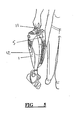
- the carry handle 11 can still move in the directions of arrow B in figure 8 to a second latent positions shown in figure 9 once the handle 5 has moved to its stowed position.
- the carry handle 11 can thus be pivoted down towards the handle 5 until it rests in contact with the lower end handle 5 when the handle is in its stowed position, thereby reducing the height of the cleaner when it is in a stowed position as shown in figure 9 .
- the outer surface of the carry handle 11 is preferably substantial in line with the outer surface of handle 5 in the area adjacent the carry handle 11.
- the carry handle end portions may be provided with a recess, into which a peg attached to a protruding portion of the main handle 5 fits. This aspect would operate in a manner similar to that described above to move carry handle 11 as handle 5 is moved from an extended position to a stowed position.
- the carry handle end portions may alternatively be disposed between the protruding portions of the handle 25.
- the handle 5 may have only one protruding portion and/or the cleaner body 3 may have more than one protruding portion.
- One or more of the end portions of the handle 11 may alternatively not be provided with a bore or be provided with a partial bore, although the spindle will extend at least through the protruding portions of the handle 5 and cleaner body 3. ,
Landscapes
- Engineering & Computer Science (AREA)
- Mechanical Engineering (AREA)
- Electric Vacuum Cleaner (AREA)
- Filters For Electric Vacuum Cleaners (AREA)
- Addition Polymer Or Copolymer, Post-Treatments, Or Chemical Modifications (AREA)
Claims (15)
- Aspirateur comprenant :un corps d'aspirateur (3) ;un manche allongé (5) relié au corps d'aspirateur (3), le manche allongé (5) étant mobile entre une position étendue, s'étendant vers l'extérieur à partir du corps d'aspirateur (3) et une position escamotée dans laquelle le manche allongé (5) est positionné de façon sensiblement adjacente au corps d'aspirateur (3) ;dans lequel l'aspirateur comprend en outre une poignée de transport (11) qui devient accessible pour l'utilisation lorsque le manche allongé (5) est déplacé de la position étendue à la position escamotée ; caractérisé en ce que la poignée de transport (11) est positionnée de façon intermédiaire entre le corps d'aspirateur (3) et le manche allongé (5).
- Aspirateur selon la revendication 1, dans lequel la poignée de transport (11) se déplace d'une position latente à une position d'accès lorsque le manche allongé est déplacé de la position étendue à la position escamotée.
- Aspirateur selon la revendication 2, dans lequel le corps d'aspirateur (3) et le manche allongé (5) possèdent une surface extérieure et, dans la position latente, la poignée de transport (11) se conforme sensiblement à la forme de la surface extérieure du corps d'aspirateur (3) et du manche allongé (5) dans une zone adjacente à la poignée de transport (11).
- Aspirateur selon une quelconque revendication précédente, dans lequel le manche allongé (5) se plie de la position étendue à la position escamotée.
- Aspirateur selon une quelconque revendication précédente, dans lequel le manche allongé (5) est monté de façon pivotante.
- Aspirateur selon une quelconque revendication précédente, dans lequel le manche allongé (5) est relié de façon pivotante au corps d'aspirateur (3).
- Aspirateur selon une quelconque revendication précédente, dans lequel la poignée de transport (11) est montée de façon pivotante.
- Aspirateur selon les revendications 4 et 5, dans lequel la poignée de transport (11) possède un axe de pivotement commun avec le manche allongé.
- Aspirateur selon la revendication précédente 2, dans lequel la poignée de transport (11) est empêchée de se déplacer de sa position d'accès à la position latente lorsque le manche allongé (5) est dans sa position escamotée.
- Aspirateur selon la revendication 9, dans lequel la poignée de transport (11) peut être déplacée de sa position d'accès à une seconde position latente lorsque le manche allongé (5) est dans sa position escamotée.
- Aspirateur selon une quelconque revendication précédente, dans lequel la poignée de transport (11) est mécaniquement en prise avec le manche allongé (5).
- Aspirateur selon une quelconque revendication précédente, dans lequel la poignée de transport (11) possède une protubérance (35) qui entre en prise dans un évidement dans le manche allongé (5) de sorte que, lorsque le manche allongé (5) pivote entre la position étendue et la position escamotée, la protubérance (35) soit déplacée, l'évidement entraînant le pivotement de la poignée de transport d'une position latente à une position d'accès.
- Aspirateur selon une quelconque revendication précédente, dans lequel la poignée de transport (11) présent sensiblement une forme de U.
- Aspirateur selon une quelconque revendication précédente, comprenant des moyens pour maintenir le manche allongé (5) dans sa position escamotée.
- Aspirateur selon une quelconque revendication précédente, comprenant en outre une partie de préhension manuelle espacée de la poignée de transport (11) .
Applications Claiming Priority (1)
| Application Number | Priority Date | Filing Date | Title |
|---|---|---|---|
| GB0525032A GB2433022A (en) | 2005-12-08 | 2005-12-08 | Vacuum cleaner with folding handle |
Publications (2)
| Publication Number | Publication Date |
|---|---|
| EP1795105A1 EP1795105A1 (fr) | 2007-06-13 |
| EP1795105B1 true EP1795105B1 (fr) | 2009-08-05 |
Family
ID=35735773
Family Applications (1)
| Application Number | Title | Priority Date | Filing Date |
|---|---|---|---|
| EP06256118A Not-in-force EP1795105B1 (fr) | 2005-12-08 | 2006-11-29 | Aspirateur |
Country Status (7)
| Country | Link |
|---|---|
| US (1) | US7681279B2 (fr) |
| EP (1) | EP1795105B1 (fr) |
| CN (1) | CN100593387C (fr) |
| AT (1) | ATE438329T1 (fr) |
| DE (1) | DE602006008253D1 (fr) |
| ES (1) | ES2332060T3 (fr) |
| GB (1) | GB2433022A (fr) |
Families Citing this family (30)
| Publication number | Priority date | Publication date | Assignee | Title |
|---|---|---|---|---|
| US9675227B2 (en) * | 2006-07-25 | 2017-06-13 | Andrew John Potoroka | Vacuum cleaner with swivel and swing handle |
| EP1955631B1 (fr) * | 2007-02-12 | 2010-11-24 | Black & Decker, Inc. | Aspirateurs |
| US9125538B2 (en) | 2012-07-27 | 2015-09-08 | Techtronic Floor Care Technology Limited | Pivoting handle for a surface cleaning device |
| EP2873358B1 (fr) * | 2013-11-15 | 2016-09-28 | Techtronic Floor Care Technology Limited | Poignée pivotante pour un dispositif de nettoyage de surface |
| US9924842B2 (en) * | 2014-06-30 | 2018-03-27 | Bissell Homecare, Inc. | Vacuum cleaner |
| CN104433959A (zh) * | 2015-01-03 | 2015-03-25 | 浙江汉斯电子科技有限公司 | 立式吸尘器 |
| JP6435204B2 (ja) * | 2015-01-28 | 2018-12-05 | 日立アプライアンス株式会社 | 電気掃除機 |
| US10966581B2 (en) | 2015-10-22 | 2021-04-06 | Sharkninja Operating Llc | Vacuum cleaning device with foldable wand to provide storage configuration |
| USD795518S1 (en) * | 2016-06-24 | 2017-08-22 | Un Hwa Chung | Rotary mop with durable gear drive unit |
| US10729295B2 (en) | 2016-08-29 | 2020-08-04 | Omachron Intellectual Property Inc. | Surface cleaning apparatus |
| US11478117B2 (en) | 2016-08-29 | 2022-10-25 | Omachron Intellectual Property Inc. | Surface cleaning apparatus |
| US10433689B2 (en) * | 2016-08-29 | 2019-10-08 | Omachron Intellectual Property Inc. | Surface cleaning apparatus |
| US10292550B2 (en) | 2016-08-29 | 2019-05-21 | Omachron Intellectual Property Inc. | Surface cleaning apparatus |
| US10405711B2 (en) | 2016-08-29 | 2019-09-10 | Omachron Intellectual Property Inc. | Surface cleaning apparatus |
| US10136779B2 (en) | 2016-08-29 | 2018-11-27 | Omachron Intellectual Property Inc. | Surface cleaning apparatus |
| US10441124B2 (en) * | 2016-08-29 | 2019-10-15 | Omachron Intellectual Property Inc. | Surface cleaning apparatus |
| US9962050B2 (en) * | 2016-08-29 | 2018-05-08 | Omachron Intellectual Property Inc. | Surface cleaning apparatus |
| US10413141B2 (en) | 2016-08-29 | 2019-09-17 | Omachron Intellectual Property Inc. | Surface cleaning apparatus |
| US10321794B2 (en) * | 2016-08-29 | 2019-06-18 | Omachron Intellectual Property Inc. | Surface cleaning apparatus |
| US10136780B2 (en) | 2016-08-29 | 2018-11-27 | Omachron Intellectual Property Inc. | Surface cleaning apparatus |
| US10441125B2 (en) * | 2016-08-29 | 2019-10-15 | Omachron Intellectual Property Inc. | Surface cleaning apparatus |
| USD834778S1 (en) * | 2017-07-25 | 2018-11-27 | Sharkninja Operating Llc | Steam mop |
| WO2019052667A1 (fr) | 2017-09-18 | 2019-03-21 | Aktiebolaget Electrolux | Aspirateur et procédé de manipulation d'un aspirateur |
| DE102018127090A1 (de) * | 2018-10-30 | 2020-04-30 | Vorwerk & Co. Interholding Gmbh | Handgeführtes Reinigungsgerät |
| CN112932321B (zh) * | 2019-12-11 | 2022-04-26 | 苏州诚河清洁设备有限公司 | 真空吸尘器 |
| JP1707470S (ja) * | 2021-06-16 | 2022-02-15 | 電気掃除機 | |
| JP1707471S (ja) * | 2021-06-16 | 2022-02-15 | 電気掃除機 | |
| EP4355187A1 (fr) | 2021-06-18 | 2024-04-24 | SharkNinja Operating LLC | Dispositif de nettoyage par aspiration comprenant un tube-rallonge pour obtenir une configuration de stockage |
| JP1707486S (ja) * | 2021-07-07 | 2022-02-15 | 電気掃除機 | |
| USD1039229S1 (en) * | 2021-10-20 | 2024-08-13 | Kingclean Electric Co., Ltd. | Floor scrubber |
Family Cites Families (5)
| Publication number | Priority date | Publication date | Assignee | Title |
|---|---|---|---|---|
| GB1036643A (en) * | 1963-04-19 | 1966-07-20 | Electrolux Ltd | Improvements in or relating to shafts for floor-treating apparatus |
| US4644605A (en) * | 1985-03-25 | 1987-02-24 | Bissell Inc. | Stick vacuum cleaner |
| IT1306930B1 (it) * | 1999-01-12 | 2001-10-11 | Gisowatt Spa | Scopa elettrica multiuso con manico ribaltabile,a scomparsa,perpavimenti,pareti,imbottiti e simili |
| JP2001218717A (ja) * | 2000-02-08 | 2001-08-14 | Hitachi Ltd | 電気掃除機 |
| WO2004096000A2 (fr) * | 2003-04-26 | 2004-11-11 | Panasonic Corporation Of North America | Poignee de manipulation tournante d'aspirateur |
-
2005
- 2005-12-08 GB GB0525032A patent/GB2433022A/en not_active Withdrawn
-
2006
- 2006-11-29 AT AT06256118T patent/ATE438329T1/de not_active IP Right Cessation
- 2006-11-29 ES ES06256118T patent/ES2332060T3/es active Active
- 2006-11-29 EP EP06256118A patent/EP1795105B1/fr not_active Not-in-force
- 2006-11-29 DE DE602006008253T patent/DE602006008253D1/de active Active
- 2006-12-06 US US11/567,345 patent/US7681279B2/en not_active Expired - Fee Related
- 2006-12-08 CN CN200610168440A patent/CN100593387C/zh not_active Expired - Fee Related
Also Published As
| Publication number | Publication date |
|---|---|
| CN1977756A (zh) | 2007-06-13 |
| ES2332060T3 (es) | 2010-01-25 |
| GB2433022A (en) | 2007-06-13 |
| DE602006008253D1 (de) | 2009-09-17 |
| ATE438329T1 (de) | 2009-08-15 |
| CN100593387C (zh) | 2010-03-10 |
| EP1795105A1 (fr) | 2007-06-13 |
| GB0525032D0 (en) | 2006-01-18 |
| US7681279B2 (en) | 2010-03-23 |
| US20070130723A1 (en) | 2007-06-14 |
Similar Documents
| Publication | Publication Date | Title |
|---|---|---|
| EP1795105B1 (fr) | Aspirateur | |
| US7950102B2 (en) | Upright vacuum cleaner having steering unit | |
| US8196257B2 (en) | Upright vacuum cleaner | |
| TWI689277B (zh) | 電動吸塵器之充電座 | |
| JP5786118B2 (ja) | 電気掃除機 | |
| EP3641611B1 (fr) | Appareil de nettoyage de surface | |
| JP6940324B2 (ja) | 電気掃除機の吸込具 | |
| US10575692B2 (en) | Vacuum cleaner | |
| JP2019030457A (ja) | 電気掃除機 | |
| EP4039153A1 (fr) | Aspirateur avec une buse rétractable | |
| JP6731358B2 (ja) | 電気掃除機の充電台 | |
| KR20220122472A (ko) | 청소기 | |
| KR20090122652A (ko) | 청소기 | |
| KR20220045857A (ko) | 진공청소기 | |
| US20090056055A1 (en) | Upright vacuum cleaner | |
| KR102268576B1 (ko) | 진공청소기 | |
| KR100194069B1 (ko) | 소형 전기 소제기 | |
| JP5578281B2 (ja) | 電気掃除機 | |
| JP2019146876A (ja) | 電気掃除機 | |
| JP7013038B2 (ja) | 袋付き電気掃除機 | |
| JP2019187581A (ja) | 電気掃除機 | |
| US20240215784A1 (en) | Cleaner | |
| CN221285597U (zh) | 罐式吸尘器附件以及包括其的罐式吸尘器 | |
| JP7400858B2 (ja) | 掃除具、電気掃除機、及びコードレス型掃除機 | |
| JP7365853B2 (ja) | 電気掃除機 |
Legal Events
| Date | Code | Title | Description |
|---|---|---|---|
| PUAI | Public reference made under article 153(3) epc to a published international application that has entered the european phase |
Free format text: ORIGINAL CODE: 0009012 |
|
| AK | Designated contracting states |
Kind code of ref document: A1 Designated state(s): AT BE BG CH CY CZ DE DK EE ES FI FR GB GR HU IE IS IT LI LT LU LV MC NL PL PT RO SE SI SK TR |
|
| AX | Request for extension of the european patent |
Extension state: AL BA HR MK YU |
|
| 17P | Request for examination filed |
Effective date: 20071211 |
|
| AKX | Designation fees paid |
Designated state(s): AT BE BG CH CY CZ DE DK EE ES FI FR GB GR HU IE IS IT LI LT LU LV MC NL PL PT RO SE SI SK TR |
|
| 17Q | First examination report despatched |
Effective date: 20080306 |
|
| GRAP | Despatch of communication of intention to grant a patent |
Free format text: ORIGINAL CODE: EPIDOSNIGR1 |
|
| GRAS | Grant fee paid |
Free format text: ORIGINAL CODE: EPIDOSNIGR3 |
|
| GRAA | (expected) grant |
Free format text: ORIGINAL CODE: 0009210 |
|
| AK | Designated contracting states |
Kind code of ref document: B1 Designated state(s): AT BE BG CH CY CZ DE DK EE ES FI FR GB GR HU IE IS IT LI LT LU LV MC NL PL PT RO SE SI SK TR |
|
| REG | Reference to a national code |
Ref country code: GB Ref legal event code: FG4D |
|
| REG | Reference to a national code |
Ref country code: CH Ref legal event code: EP |
|
| REG | Reference to a national code |
Ref country code: IE Ref legal event code: FG4D |
|
| REF | Corresponds to: |
Ref document number: 602006008253 Country of ref document: DE Date of ref document: 20090917 Kind code of ref document: P |
|
| LTIE | Lt: invalidation of european patent or patent extension |
Effective date: 20090805 |
|
| REG | Reference to a national code |
Ref country code: ES Ref legal event code: FG2A Ref document number: 2332060 Country of ref document: ES Kind code of ref document: T3 |
|
| PG25 | Lapsed in a contracting state [announced via postgrant information from national office to epo] |
Ref country code: AT Free format text: LAPSE BECAUSE OF FAILURE TO SUBMIT A TRANSLATION OF THE DESCRIPTION OR TO PAY THE FEE WITHIN THE PRESCRIBED TIME-LIMIT Effective date: 20090805 Ref country code: SE Free format text: LAPSE BECAUSE OF FAILURE TO SUBMIT A TRANSLATION OF THE DESCRIPTION OR TO PAY THE FEE WITHIN THE PRESCRIBED TIME-LIMIT Effective date: 20090805 Ref country code: LT Free format text: LAPSE BECAUSE OF FAILURE TO SUBMIT A TRANSLATION OF THE DESCRIPTION OR TO PAY THE FEE WITHIN THE PRESCRIBED TIME-LIMIT Effective date: 20090805 Ref country code: FI Free format text: LAPSE BECAUSE OF FAILURE TO SUBMIT A TRANSLATION OF THE DESCRIPTION OR TO PAY THE FEE WITHIN THE PRESCRIBED TIME-LIMIT Effective date: 20090805 Ref country code: IS Free format text: LAPSE BECAUSE OF FAILURE TO SUBMIT A TRANSLATION OF THE DESCRIPTION OR TO PAY THE FEE WITHIN THE PRESCRIBED TIME-LIMIT Effective date: 20091205 |
|
| NLV1 | Nl: lapsed or annulled due to failure to fulfill the requirements of art. 29p and 29m of the patents act | ||
| PG25 | Lapsed in a contracting state [announced via postgrant information from national office to epo] |
Ref country code: PL Free format text: LAPSE BECAUSE OF FAILURE TO SUBMIT A TRANSLATION OF THE DESCRIPTION OR TO PAY THE FEE WITHIN THE PRESCRIBED TIME-LIMIT Effective date: 20090805 Ref country code: LV Free format text: LAPSE BECAUSE OF FAILURE TO SUBMIT A TRANSLATION OF THE DESCRIPTION OR TO PAY THE FEE WITHIN THE PRESCRIBED TIME-LIMIT Effective date: 20090805 Ref country code: NL Free format text: LAPSE BECAUSE OF FAILURE TO SUBMIT A TRANSLATION OF THE DESCRIPTION OR TO PAY THE FEE WITHIN THE PRESCRIBED TIME-LIMIT Effective date: 20090805 Ref country code: SI Free format text: LAPSE BECAUSE OF FAILURE TO SUBMIT A TRANSLATION OF THE DESCRIPTION OR TO PAY THE FEE WITHIN THE PRESCRIBED TIME-LIMIT Effective date: 20090805 |
|
| PG25 | Lapsed in a contracting state [announced via postgrant information from national office to epo] |
Ref country code: BG Free format text: LAPSE BECAUSE OF FAILURE TO SUBMIT A TRANSLATION OF THE DESCRIPTION OR TO PAY THE FEE WITHIN THE PRESCRIBED TIME-LIMIT Effective date: 20091105 Ref country code: PT Free format text: LAPSE BECAUSE OF FAILURE TO SUBMIT A TRANSLATION OF THE DESCRIPTION OR TO PAY THE FEE WITHIN THE PRESCRIBED TIME-LIMIT Effective date: 20091205 |
|
| PG25 | Lapsed in a contracting state [announced via postgrant information from national office to epo] |
Ref country code: RO Free format text: LAPSE BECAUSE OF FAILURE TO SUBMIT A TRANSLATION OF THE DESCRIPTION OR TO PAY THE FEE WITHIN THE PRESCRIBED TIME-LIMIT Effective date: 20090805 Ref country code: DK Free format text: LAPSE BECAUSE OF FAILURE TO SUBMIT A TRANSLATION OF THE DESCRIPTION OR TO PAY THE FEE WITHIN THE PRESCRIBED TIME-LIMIT Effective date: 20090805 Ref country code: CZ Free format text: LAPSE BECAUSE OF FAILURE TO SUBMIT A TRANSLATION OF THE DESCRIPTION OR TO PAY THE FEE WITHIN THE PRESCRIBED TIME-LIMIT Effective date: 20090805 Ref country code: EE Free format text: LAPSE BECAUSE OF FAILURE TO SUBMIT A TRANSLATION OF THE DESCRIPTION OR TO PAY THE FEE WITHIN THE PRESCRIBED TIME-LIMIT Effective date: 20090805 |
|
| PG25 | Lapsed in a contracting state [announced via postgrant information from national office to epo] |
Ref country code: SK Free format text: LAPSE BECAUSE OF FAILURE TO SUBMIT A TRANSLATION OF THE DESCRIPTION OR TO PAY THE FEE WITHIN THE PRESCRIBED TIME-LIMIT Effective date: 20090805 |
|
| PLBE | No opposition filed within time limit |
Free format text: ORIGINAL CODE: 0009261 |
|
| STAA | Information on the status of an ep patent application or granted ep patent |
Free format text: STATUS: NO OPPOSITION FILED WITHIN TIME LIMIT |
|
| PG25 | Lapsed in a contracting state [announced via postgrant information from national office to epo] |
Ref country code: BE Free format text: LAPSE BECAUSE OF FAILURE TO SUBMIT A TRANSLATION OF THE DESCRIPTION OR TO PAY THE FEE WITHIN THE PRESCRIBED TIME-LIMIT Effective date: 20090805 Ref country code: MC Free format text: LAPSE BECAUSE OF NON-PAYMENT OF DUE FEES Effective date: 20091130 |
|
| 26N | No opposition filed |
Effective date: 20100507 |
|
| PG25 | Lapsed in a contracting state [announced via postgrant information from national office to epo] |
Ref country code: IE Free format text: LAPSE BECAUSE OF NON-PAYMENT OF DUE FEES Effective date: 20091129 Ref country code: GR Free format text: LAPSE BECAUSE OF FAILURE TO SUBMIT A TRANSLATION OF THE DESCRIPTION OR TO PAY THE FEE WITHIN THE PRESCRIBED TIME-LIMIT Effective date: 20091106 |
|
| PG25 | Lapsed in a contracting state [announced via postgrant information from national office to epo] |
Ref country code: LU Free format text: LAPSE BECAUSE OF NON-PAYMENT OF DUE FEES Effective date: 20091129 |
|
| PG25 | Lapsed in a contracting state [announced via postgrant information from national office to epo] |
Ref country code: HU Free format text: LAPSE BECAUSE OF FAILURE TO SUBMIT A TRANSLATION OF THE DESCRIPTION OR TO PAY THE FEE WITHIN THE PRESCRIBED TIME-LIMIT Effective date: 20100206 |
|
| REG | Reference to a national code |
Ref country code: CH Ref legal event code: PL |
|
| PG25 | Lapsed in a contracting state [announced via postgrant information from national office to epo] |
Ref country code: CH Free format text: LAPSE BECAUSE OF NON-PAYMENT OF DUE FEES Effective date: 20101130 Ref country code: LI Free format text: LAPSE BECAUSE OF NON-PAYMENT OF DUE FEES Effective date: 20101130 |
|
| PG25 | Lapsed in a contracting state [announced via postgrant information from national office to epo] |
Ref country code: TR Free format text: LAPSE BECAUSE OF FAILURE TO SUBMIT A TRANSLATION OF THE DESCRIPTION OR TO PAY THE FEE WITHIN THE PRESCRIBED TIME-LIMIT Effective date: 20090805 |
|
| PG25 | Lapsed in a contracting state [announced via postgrant information from national office to epo] |
Ref country code: CY Free format text: LAPSE BECAUSE OF FAILURE TO SUBMIT A TRANSLATION OF THE DESCRIPTION OR TO PAY THE FEE WITHIN THE PRESCRIBED TIME-LIMIT Effective date: 20090805 |
|
| REG | Reference to a national code |
Ref country code: FR Ref legal event code: PLFP Year of fee payment: 10 |
|
| PGFP | Annual fee paid to national office [announced via postgrant information from national office to epo] |
Ref country code: IT Payment date: 20151109 Year of fee payment: 10 |
|
| PGFP | Annual fee paid to national office [announced via postgrant information from national office to epo] |
Ref country code: FR Payment date: 20151130 Year of fee payment: 10 Ref country code: ES Payment date: 20151023 Year of fee payment: 10 |
|
| PGFP | Annual fee paid to national office [announced via postgrant information from national office to epo] |
Ref country code: DE Payment date: 20160129 Year of fee payment: 10 |
|
| REG | Reference to a national code |
Ref country code: DE Ref legal event code: R119 Ref document number: 602006008253 Country of ref document: DE |
|
| REG | Reference to a national code |
Ref country code: FR Ref legal event code: ST Effective date: 20170731 |
|
| PG25 | Lapsed in a contracting state [announced via postgrant information from national office to epo] |
Ref country code: IT Free format text: LAPSE BECAUSE OF NON-PAYMENT OF DUE FEES Effective date: 20161129 Ref country code: FR Free format text: LAPSE BECAUSE OF NON-PAYMENT OF DUE FEES Effective date: 20161130 |
|
| PG25 | Lapsed in a contracting state [announced via postgrant information from national office to epo] |
Ref country code: DE Free format text: LAPSE BECAUSE OF NON-PAYMENT OF DUE FEES Effective date: 20170601 |
|
| PG25 | Lapsed in a contracting state [announced via postgrant information from national office to epo] |
Ref country code: ES Free format text: LAPSE BECAUSE OF NON-PAYMENT OF DUE FEES Effective date: 20161130 |
|
| REG | Reference to a national code |
Ref country code: ES Ref legal event code: FD2A Effective date: 20180626 |
|
| PGFP | Annual fee paid to national office [announced via postgrant information from national office to epo] |
Ref country code: GB Payment date: 20201120 Year of fee payment: 15 |
|
| GBPC | Gb: european patent ceased through non-payment of renewal fee |
Effective date: 20211129 |
|
| PG25 | Lapsed in a contracting state [announced via postgrant information from national office to epo] |
Ref country code: GB Free format text: LAPSE BECAUSE OF NON-PAYMENT OF DUE FEES Effective date: 20211129 |