EP1793107B1 - Procédé de controle de l'admission d'un moteur à combustion interne, notamment de type essence ou Diesel, et moteurs utilisant un tel procédé - Google Patents
Procédé de controle de l'admission d'un moteur à combustion interne, notamment de type essence ou Diesel, et moteurs utilisant un tel procédé Download PDFInfo
- Publication number
- EP1793107B1 EP1793107B1 EP06291810.7A EP06291810A EP1793107B1 EP 1793107 B1 EP1793107 B1 EP 1793107B1 EP 06291810 A EP06291810 A EP 06291810A EP 1793107 B1 EP1793107 B1 EP 1793107B1
- Authority
- EP
- European Patent Office
- Prior art keywords
- cylinders
- engine
- intake
- group
- controlling
- Prior art date
- Legal status (The legal status is an assumption and is not a legal conclusion. Google has not performed a legal analysis and makes no representation as to the accuracy of the status listed.)
- Not-in-force
Links
- 238000002485 combustion reaction Methods 0.000 title claims description 34
- 238000000034 method Methods 0.000 title claims description 31
- 239000000446 fuel Substances 0.000 claims description 36
- 238000002347 injection Methods 0.000 claims description 15
- 239000007924 injection Substances 0.000 claims description 15
- 239000000203 mixture Substances 0.000 claims description 13
- 239000007789 gas Substances 0.000 description 38
- 239000003054 catalyst Substances 0.000 description 30
- 239000003570 air Substances 0.000 description 12
- 239000003344 environmental pollutant Substances 0.000 description 7
- 231100000719 pollutant Toxicity 0.000 description 7
- UGFAIRIUMAVXCW-UHFFFAOYSA-N Carbon monoxide Chemical compound [O+]#[C-] UGFAIRIUMAVXCW-UHFFFAOYSA-N 0.000 description 6
- 229910002091 carbon monoxide Inorganic materials 0.000 description 6
- 229930195733 hydrocarbon Natural products 0.000 description 6
- MWUXSHHQAYIFBG-UHFFFAOYSA-N nitrogen oxide Inorganic materials O=[N] MWUXSHHQAYIFBG-UHFFFAOYSA-N 0.000 description 5
- 239000000243 solution Substances 0.000 description 5
- 150000002430 hydrocarbons Chemical class 0.000 description 4
- 230000037452 priming Effects 0.000 description 3
- 230000009471 action Effects 0.000 description 2
- 239000012080 ambient air Substances 0.000 description 2
- 230000003416 augmentation Effects 0.000 description 2
- 238000011156 evaluation Methods 0.000 description 2
- 230000006870 function Effects 0.000 description 2
- 239000003502 gasoline Substances 0.000 description 2
- 230000008569 process Effects 0.000 description 2
- 238000011144 upstream manufacturing Methods 0.000 description 2
- QVGXLLKOCUKJST-UHFFFAOYSA-N atomic oxygen Chemical compound [O] QVGXLLKOCUKJST-UHFFFAOYSA-N 0.000 description 1
- 230000003197 catalytic effect Effects 0.000 description 1
- 230000008859 change Effects 0.000 description 1
- 238000006243 chemical reaction Methods 0.000 description 1
- 238000004140 cleaning Methods 0.000 description 1
- 230000006735 deficit Effects 0.000 description 1
- 230000001419 dependent effect Effects 0.000 description 1
- 239000012530 fluid Substances 0.000 description 1
- 239000002737 fuel gas Substances 0.000 description 1
- -1 hydrocarbons HC Chemical class 0.000 description 1
- 230000000977 initiatory effect Effects 0.000 description 1
- 238000013507 mapping Methods 0.000 description 1
- 210000000056 organ Anatomy 0.000 description 1
- 230000003647 oxidation Effects 0.000 description 1
- 238000007254 oxidation reaction Methods 0.000 description 1
- 230000001590 oxidative effect Effects 0.000 description 1
- 239000001301 oxygen Substances 0.000 description 1
- 229910052760 oxygen Inorganic materials 0.000 description 1
- 230000001737 promoting effect Effects 0.000 description 1
- 230000009467 reduction Effects 0.000 description 1
- 238000004904 shortening Methods 0.000 description 1
Images

Classifications
-
- F—MECHANICAL ENGINEERING; LIGHTING; HEATING; WEAPONS; BLASTING
- F02—COMBUSTION ENGINES; HOT-GAS OR COMBUSTION-PRODUCT ENGINE PLANTS
- F02D—CONTROLLING COMBUSTION ENGINES
- F02D41/00—Electrical control of supply of combustible mixture or its constituents
- F02D41/02—Circuit arrangements for generating control signals
- F02D41/021—Introducing corrections for particular conditions exterior to the engine
- F02D41/0235—Introducing corrections for particular conditions exterior to the engine in relation with the state of the exhaust gas treating apparatus
- F02D41/024—Introducing corrections for particular conditions exterior to the engine in relation with the state of the exhaust gas treating apparatus to increase temperature of the exhaust gas treating apparatus
- F02D41/0245—Introducing corrections for particular conditions exterior to the engine in relation with the state of the exhaust gas treating apparatus to increase temperature of the exhaust gas treating apparatus by increasing temperature of the exhaust gas leaving the engine
-
- F—MECHANICAL ENGINEERING; LIGHTING; HEATING; WEAPONS; BLASTING
- F02—COMBUSTION ENGINES; HOT-GAS OR COMBUSTION-PRODUCT ENGINE PLANTS
- F02D—CONTROLLING COMBUSTION ENGINES
- F02D17/00—Controlling engines by cutting out individual cylinders; Rendering engines inoperative or idling
- F02D17/02—Cutting-out
-
- Y—GENERAL TAGGING OF NEW TECHNOLOGICAL DEVELOPMENTS; GENERAL TAGGING OF CROSS-SECTIONAL TECHNOLOGIES SPANNING OVER SEVERAL SECTIONS OF THE IPC; TECHNICAL SUBJECTS COVERED BY FORMER USPC CROSS-REFERENCE ART COLLECTIONS [XRACs] AND DIGESTS
- Y02—TECHNOLOGIES OR APPLICATIONS FOR MITIGATION OR ADAPTATION AGAINST CLIMATE CHANGE
- Y02T—CLIMATE CHANGE MITIGATION TECHNOLOGIES RELATED TO TRANSPORTATION
- Y02T10/00—Road transport of goods or passengers
- Y02T10/10—Internal combustion engine [ICE] based vehicles
- Y02T10/12—Improving ICE efficiencies
-
- Y—GENERAL TAGGING OF NEW TECHNOLOGICAL DEVELOPMENTS; GENERAL TAGGING OF CROSS-SECTIONAL TECHNOLOGIES SPANNING OVER SEVERAL SECTIONS OF THE IPC; TECHNICAL SUBJECTS COVERED BY FORMER USPC CROSS-REFERENCE ART COLLECTIONS [XRACs] AND DIGESTS
- Y02—TECHNOLOGIES OR APPLICATIONS FOR MITIGATION OR ADAPTATION AGAINST CLIMATE CHANGE
- Y02T—CLIMATE CHANGE MITIGATION TECHNOLOGIES RELATED TO TRANSPORTATION
- Y02T10/00—Road transport of goods or passengers
- Y02T10/10—Internal combustion engine [ICE] based vehicles
- Y02T10/40—Engine management systems
Definitions
- the present invention relates to a method for controlling the admission of an internal combustion engine, in particular of the Gasoline or Diesel type, and to engines using such a method.
- the exhaust gas is discharged into the atmosphere through an exhaust line which carries a means of cleaning up these exhaust gases before they are released into this atmosphere.
- this means of depollution is a catalyst traversed by these gases and which is intended to eliminate certain pollutants they contain.
- the catalyst more particularly the so-called "three-way” catalyst, has the main functions of oxidizing unburned hydrocarbons (HC) as well as carbon monoxide (CO) and of reducing the nitrogen oxides (NOx), which are the pollutants usually present in the exhaust.
- this type of catalyst can only fulfill its role when it has reached a minimum starting or operating temperature, referred to as the "light off" temperature (of the order of 200 ° C.).
- This temperature level is essential to allow the reaction between the catalytic elements carried by the catalyst and the pollutants contained in the exhaust gas.
- the temperature rise of the catalyst is not fast enough, resulting in a rejection of untreated exhaust gas in the engine. atmosphere. Consequently, an increase in the speed of the rise in temperature of this catalyst is necessary to ensure the depollution of the exhaust gas and thus comply with the standards applied to engines of motor vehicles that are becoming more severe.
- the present invention proposes to overcome the above disadvantages through an engine intake method which allows to rapidly raise the temperature of the exhaust gas while shortening the the time required for the priming of the catalyst and this by minimizing overconsumption of fuel while reducing the emissions of pollutants that are produced and untreated during the rise in temperature of the catalyst, up to its priming temperature.
- This method can consist in admitting in one of the groups of cylinders at most the totality of the total charge.
- It may also consist in admitting, in one of the groups of cylinders, a proportion substantially equal to 75% of the total upper load and in admitting, in the other group of cylinders, the remainder of the total load.
- the charge may consist of the amount of fuel to be injected into the cylinders.
- This charge may also consist of the amount of fuel mixture to be introduced into the cylinders.
- the method may include permuting the admission of the highest proportion of the total charge between the at least two groups of cylinders.
- the figure 1 shows an example of a direct injection internal combustion engine, particularly a diesel engine, using the method according to the invention.
- This engine comprises at least two cylinders or at least two groups of at least one cylinder within which the combustion of a fuel mixture is carried out.
- the engine comprises four cylinders 10 numbered C1 to C4 from the bottom of the figure 1 , for a better understanding of the following description.
- the engine of this figure 1 operates according to the ignition cycle said 1, 3, 4, 2, which is well known to those skilled in the art. From this, these cylinders are separated into two groups 12, 14 of two cylinders with for the group 12 the cylinders C1 and C4 and for the group 14 the cylinders C3 and C2.
- This example does not exclude all other configurations, such as two groups with a group of three cylinders C1, C4, C3 and a group of a cylinder C2 or all configurations dependent on the ignition cycle.
- Each cylinder comprises at least one intake means 16 with an intake valve 18 and an intake manifold 20, at least one exhaust means 22 with an exhaust valve 24 and an exhaust manifold 26, and fuel injection means 28, such as an injection ramp 30 carrying injectors 32 for directly introducing fuel into the cylinders.
- the pipes 20 of the intake means 16 are connected to an intake manifold 34 in which ambient air or supercharged air is introduced through a pipe 36.
- the pipes 26 of the exhaust means 22 terminate in an intake manifold.
- exhaust manifold 38 which is associated with an exhaust line 40.
- This exhaust line carries pollution control means 42 of the exhaust gas flowing in this line and more particularly but not exclusively an oxidation catalyst in the case diesel engine, as illustrated in the figure 1 .
- this engine comprises exhaust gas recirculation means, known as EGR for "Exhaust Gas Recirculation", which allow to reintroduce exhaust gases burned into the cylinders.
- EGR exhaust gas recirculation means
- This recirculation makes it possible to control the combustion of the fuel with the fluid (s) therein (s). More particularly, the reintroduction of these exhaust gases makes it possible to measure the amount of oxygen present in these cylinders to ensure combustion with the fuel injected.
- this EGR consists of two separate EGR circuits 44 and 46.
- the circuit 44 comprises an exhaust gas recirculation pipe 48 which originates on the exhaust line 40 at a point 50 located downstream of the exhaust manifold 38 and upstream of the catalyst 42.
- This pipe separates, in the vicinity of the intake manifold, into two branches that end in the same group of cylinders. More specifically, for the group 12, a branch 52 leads to the intake manifold 20 of the cylinder C1 and another branch 54 leads to the intake manifold of the cylinder C4.
- This circuit also comprises a valve 56, called the EGR valve, located between the point 50 and the branches 52, 54 and which makes it possible to control the amount of exhaust gas flowing in the pipe 48.
- the EGR circuit 46 also comprises a control pipe.
- exhaust gas recirculation 58 which starts at point 50 and separates, in the vicinity of the intake manifold, into two branches 60, 62. These branches result in the group 14 of cylinders and more precisely to the intake manifold 20 of cylinder C2 and cylinder C3.
- the pipe 58 carries an EGR valve 64 placed in the same configuration as the valve 56.
- an engine control unit 66 such as a motor computer, controls the operation of the engine.
- This unit contains mappings or tables of data making it possible to evaluate, as a function of the operating conditions of the engine, as the engine speed, the parameters necessary for its operation.
- This calculator also makes it possible to control the organs of this engine, such as the means fuel injection 28 by a control line 68 and the valves 56 and 64 by a control line 70, 72.
- the engine-calculator determines whether this engine is with a cold operation or if the engine is hot but operates with low speeds and / or low torque, in particular thanks to the temperature sensor that usually includes this engine.
- this computer controls the different members of this engine so as to increase the temperature of the exhaust gas to shorten the time required for the catalyst 42 to be operational when it has reached its priming temperature or the temperature of operation of this catalyst is maintained.
- one of the groups of cylinders receives a larger amount of load than the other and this without changing the overall load of the engine.
- one of the groups receives 75% of the initial total charge and the other of the groups the rest of this charge, that is 25%.
- this asymmetry can be even greater until the operating break of a group of cylinders by introducing no load.
- the intake and exhaust valves of this cylinder remain activated so as to use the work of transferring gases through these valves. This makes it possible to increase the load of the group of cylinders in operation and thus to participate in the increase of the temperature of the exhaust gases.
- the computer contains in its memory or its tables, an evaluation of the total amount of fuel that must be injected into the four cylinders during the cold operation phase.
- this computer controls the injectors 32 so that the distribution of the fuel is realized. in an asymmetrical way for each group of cylinders.
- one of the groups of cylinders for example the group 12 with the cylinders C1 and C4, receives a proportion of the overall quantity of fuel larger than that of the other group with the cylinders C2 and C3.
- the computer controls the injectors 32 so as to switch the groups of cylinders after operation of a certain duration, for example every 10 seconds.
- the group 14 of cylinders C2 and C3 receives the largest proportion of fuel and the group 12 of cylinder C1 and C4, the least important proportion.
- the under-advance can be all the more important that the load of the cylinder is high.
- the computer 66 controls the various components of the engine so as to distribute the load equally in each cylinder.
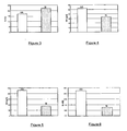
- the figure 3 shows, during a cold operation, the temperature of the exhaust gases (T in degrees Celsius) of an engine operating according to the method of the state of the art (AA) with a load distributed equitably between the cylinders and that of an engine operating according to the method of the invention (N). It can be seen that this temperature T increases by about 50 ° C. between the temperature of the engine exhaust gases using the method according to the prior art and that of the engine using the method according to the invention.
- the emissions of pollutants are greatly reduced, of the order of 36%, for unburned hydrocarbons HC ( figure 4 with HC in grams per hour) and, in the order of 62%, for carbon monoxide CO ( figure 5 with CO in grams per hour).
- the combustion noise B ( figure 6 with B in decibel) is reduced by about 0.6 dB compared to the method of the state of the art.
- figure 2 shows a variant of the figure 1 with a use of the method according to the invention in connection with a gasoline-type direct injection internal combustion engine, generally operating at stoichiometry.
- the present invention can also be applied to a sequential injection gasoline-type internal combustion engine with at least one intake manifold fuel injector making it possible to indirectly inject this fuel.
- This engine also comprises two groups 12, 14 of two cylinders, referenced C1 and C4 for the group 12 and C2 and C3 for the group 14.
- Each cylinder comprises at least one intake means 16 with an intake valve 18 and a intake manifold 20, at least one exhaust means 22 with an exhaust valve 24 and an exhaust manifold 26, and an indirect fuel injection means 74, for example an injection manifold 76 with injectors 78 introducing fuel into the cylinders to make a fuel mixture.
- the pipes 20 of the group 12 of cylinders C1 and C4 are connected to an intake manifold 80 in which intake air (ambient air or supercharged air) is introduced via a pipe 82 whose passage is controlled by means shutter, such as a butterfly flap 84.
- the tubes 20 of the group 14 of cylinders C2 and C3 are also connected to another intake manifold 86 into which intake air is introduced through a pipe 88 controlled by a butterfly flap 90.
- the cylinders comprise, as known per se, means for igniting the fuel mixture, such as a candle 91.
- the exhaust pipes 26 of the group 12 of cylinders C1 and C4 are connected to an exhaust manifold 92 from which an exhaust line 94 carrying a means of depollution of exhaust gas, like a three-way catalyst 96.
- the exhaust pipes 26 of the group 14 of cylinders C2 and C3 are connected to an exhaust manifold 98 with an exhaust line 100 and a depollution means 102, as a three-way catalysts.
- the lines 94 and 100 can join downstream of the catalysts 96 and 102 to form a single exhaust line (not shown).
- the engine also includes a motor calculator 66 for controlling the operation of the motor.
- This computer makes it possible in particular to control the injectors 78 by a control line 104 and the butterfly flaps 84, 90 by a control line 106 and 108 and the candles 91 by a control line not shown.
- asymmetry of the load is performed to increase the temperature of the exhaust gas for cold operation of the engine or hot with low speeds and / or low torques.
- the computer evaluates the total load to be injected into the four cylinders during the conventional cold operating phase and which corresponds to the total amount of fuel mixture (air or supercharged air supplemented with fuel) to be introduced into the four cylinders. cylinders. From this evaluation, this computer controls the injectors 78 and the flaps 84, 90 so that the distribution of the fuel mixture is done in such a way that a quantity of fuel mixture is greater in a cylinder group , for example the group 12 with the cylinders C1 and C4, than that of the other group 14 with the cylinders C2 and C3.
- the computer 66 controls the injectors 78 and the flaps 84, 90 so as to change the proportions of the load in the groups of cylinders after operation of a certain duration, for example every 10 seconds.
- the group 14 of cylinders C2 and C3 receives the largest amount of fuel mixture and the cylinder group 12 C1 and C4, the least amount.
- the computer 66 controls the injectors 78 and the flaps 84, 90 so that the load is evenly distributed in the groups of cylinders and therefore in each cylinder.
Landscapes
- Engineering & Computer Science (AREA)
- Chemical & Material Sciences (AREA)
- Combustion & Propulsion (AREA)
- Mechanical Engineering (AREA)
- General Engineering & Computer Science (AREA)
- Electrical Control Of Air Or Fuel Supplied To Internal-Combustion Engine (AREA)
- Exhaust Gas After Treatment (AREA)
- Combined Controls Of Internal Combustion Engines (AREA)
- Output Control And Ontrol Of Special Type Engine (AREA)
Applications Claiming Priority (1)
| Application Number | Priority Date | Filing Date | Title |
|---|---|---|---|
| FR0512286A FR2893986B1 (fr) | 2005-11-30 | 2005-11-30 | Procede de controle de l'admission d'un moteur a combustion interne, notamment de type essence ou diesel, et moteurs utilisant un tel procede. |
Publications (2)
| Publication Number | Publication Date |
|---|---|
| EP1793107A1 EP1793107A1 (fr) | 2007-06-06 |
| EP1793107B1 true EP1793107B1 (fr) | 2013-05-01 |
Family
ID=36764524
Family Applications (1)
| Application Number | Title | Priority Date | Filing Date |
|---|---|---|---|
| EP06291810.7A Not-in-force EP1793107B1 (fr) | 2005-11-30 | 2006-11-22 | Procédé de controle de l'admission d'un moteur à combustion interne, notamment de type essence ou Diesel, et moteurs utilisant un tel procédé |
Country Status (4)
| Country | Link |
|---|---|
| US (1) | US8091340B2 (enExample) |
| EP (1) | EP1793107B1 (enExample) |
| JP (1) | JP2007162685A (enExample) |
| FR (1) | FR2893986B1 (enExample) |
Families Citing this family (1)
| Publication number | Priority date | Publication date | Assignee | Title |
|---|---|---|---|---|
| WO2015080633A1 (en) | 2013-11-29 | 2015-06-04 | Volvo Construction Equipment Ab | An internal combustion engine and a method for controlling an internal combustion engine |
Citations (1)
| Publication number | Priority date | Publication date | Assignee | Title |
|---|---|---|---|---|
| JP2002155738A (ja) * | 2000-11-20 | 2002-05-31 | Nissan Motor Co Ltd | 内燃機関の排気浄化装置 |
Family Cites Families (15)
| Publication number | Priority date | Publication date | Assignee | Title |
|---|---|---|---|---|
| US4395875A (en) * | 1981-07-24 | 1983-08-02 | Texaco Inc. | Method for rejuvenating an exhaust gas filter for a diesel engine |
| JPS5874841A (ja) * | 1981-10-28 | 1983-05-06 | Nissan Motor Co Ltd | 気筒数制御エンジン |
| JPS58119942A (ja) * | 1982-01-12 | 1983-07-16 | Nissan Motor Co Ltd | 気筒数制御エンジン |
| JPH0219627A (ja) * | 1988-07-08 | 1990-01-23 | Mitsubishi Motors Corp | 空燃比制御方法 |
| GB2304602A (en) * | 1995-08-26 | 1997-03-26 | Ford Motor Co | Engine with cylinder deactivation |
| DE19812829B4 (de) * | 1997-03-27 | 2008-08-21 | Volkswagen Ag | Verfahren für die Regelung einer Brennkraftmaschine mit innerer Verbrennung |
| DE19758018A1 (de) * | 1997-12-29 | 1999-07-01 | Volkswagen Ag | Regeneration eines NOx-Speicherkatalysators eines Verbrennungsmotors |
| US7181759B2 (en) * | 2000-05-26 | 2007-02-20 | Bigband Networks, Inc. | System and method for providing interactivity for end-users over digital broadcast channels |
| US6415601B1 (en) * | 2000-12-07 | 2002-07-09 | Ford Global Technologies, Inc. | Temperature management of catalyst system for a variable displacement engine |
| US6389806B1 (en) * | 2000-12-07 | 2002-05-21 | Ford Global Technologies, Inc. | Variable displacement engine control for fast catalyst light-off |
| JP3968556B2 (ja) * | 2001-07-18 | 2007-08-29 | 三菱ふそうトラック・バス株式会社 | 内燃機関の排気浄化装置 |
| EP1458965A1 (en) * | 2001-11-30 | 2004-09-22 | Delphi Technologies, Inc. | Cylinder deactivation to improve vehicle interior heating |
| JP2003201891A (ja) * | 2001-12-27 | 2003-07-18 | Denso Corp | 多気筒内燃機関の触媒早期暖機運転制御装置 |
| US6857264B2 (en) * | 2002-12-19 | 2005-02-22 | General Motors Corporation | Exhaust emission aftertreatment |
| US6907725B2 (en) * | 2003-04-30 | 2005-06-21 | General Motors Corporation | Method for reducing engine exhaust emissions |
-
2005
- 2005-11-30 FR FR0512286A patent/FR2893986B1/fr not_active Expired - Fee Related
-
2006
- 2006-11-22 EP EP06291810.7A patent/EP1793107B1/fr not_active Not-in-force
- 2006-11-29 US US11/564,457 patent/US8091340B2/en not_active Expired - Fee Related
- 2006-11-29 JP JP2006321070A patent/JP2007162685A/ja active Pending
Patent Citations (1)
| Publication number | Priority date | Publication date | Assignee | Title |
|---|---|---|---|---|
| JP2002155738A (ja) * | 2000-11-20 | 2002-05-31 | Nissan Motor Co Ltd | 内燃機関の排気浄化装置 |
Also Published As
| Publication number | Publication date |
|---|---|
| US8091340B2 (en) | 2012-01-10 |
| JP2007162685A (ja) | 2007-06-28 |
| FR2893986B1 (fr) | 2008-01-04 |
| FR2893986A1 (fr) | 2007-06-01 |
| EP1793107A1 (fr) | 2007-06-06 |
| US20070157603A1 (en) | 2007-07-12 |
Similar Documents
| Publication | Publication Date | Title |
|---|---|---|
| CN101438042A (zh) | 内燃发动机的控制设备和控制方法 | |
| FR2792036A1 (fr) | Systeme d'aide a la regeneration d'un filtre a particules integre dans une ligne d'echappement d'un moteur diesel notamment de vehicule automobile | |
| EP1793107B1 (fr) | Procédé de controle de l'admission d'un moteur à combustion interne, notamment de type essence ou Diesel, et moteurs utilisant un tel procédé | |
| FR2920030A3 (fr) | Systeme et procede de regeneration de filtre a particules d'un moteur a combustion | |
| FR2818687A1 (fr) | Dispositif de purification des gaz d'echappement et procede pour un moteur a combustion interne | |
| EP3077637B1 (fr) | Procédé d'optimisation de la détection d'un catalyseur défaillant | |
| EP3673165B1 (fr) | Procede de pilotage d'un moteur thermique en fonction de conditions thermodynamiques dans les lignes d'admission et d'echappement | |
| FR2928967A1 (fr) | Regeneration sans surchauffe d'un dispositif de post-traitement de vehicule automobile | |
| FR2930800A1 (fr) | Installation de depollution des gaz d'echappement d'un moteur a combustion interne du type a cylindres selectivement actifs ou inactifs et procede utilisant une telle installation | |
| EP2078839B1 (fr) | Strategie de chauffage rapide pour compenser le vieillissement d'un catalyseur d'oxydation d'un moteur diesel | |
| FR2960261A1 (fr) | Procede de controle de la combustion d'un moteur a combustion interne bicarburation, notamment pour vehicule automobile | |
| WO2022184480A1 (fr) | Procédé et système de commande d'un moteur à combustion interne à allumage commandé en phase de levé de pied. | |
| FR2721653A1 (fr) | Procédé et dispositif de réduction des émissions de polluants d'un moteur à combustion interne. | |
| FR3153377A1 (fr) | Procédé de pilotage d’un moteur à combustion interne | |
| FR3088957A1 (fr) | Dispositif et procédé de commande de la régénération d'un filtre à particules d'une ligne d'échappement d'un moteur à combustion interne | |
| FR3162791A1 (fr) | Procédé de détermination d’un volume d’air d’une réserve d’air pour un moteur à combustion interne d’un véhicule | |
| FR3051227A1 (fr) | Procede de commande d'un moteur a allumage commande | |
| WO2005064129A1 (fr) | Systeme d'aide a la regeneration de moyens de depollution integres dans une ligne d'echappement d'un moteur de vehicule automobile | |
| FR2881177A1 (fr) | Procede de desulfuration d'un moteur de vehicule | |
| EP2444640A1 (fr) | Procédé de commande de la régéneration d'un filtre à particules | |
| FR2983531A1 (fr) | Alimentation en mode riche d'un moteur a combustion interne a double pre-injection | |
| FR3029571A3 (fr) | Procede de controle d'un dispositif de motorisation et dispositif de motorisation associe | |
| FR2779775A1 (fr) | Dispositif et procede d'alimentation en carburant d'un moteur a combustion interne | |
| FR3102799A1 (fr) | Procédé de REGENERATION D’UN PIEGE A OXYDES D’AZOTE DE MOTEUR A COMBUSTION INTERNE EQUIPE D’UN CATALYSEUR DE REDUCTION SELECTIVE DES OXYDES D’AZOTE, ET DISPOSITIF ASSOCIE | |
| FR2804997A1 (fr) | Procede d'injection de carburant pour la regeneration d'un piege a oxydes d'azote |
Legal Events
| Date | Code | Title | Description |
|---|---|---|---|
| PUAI | Public reference made under article 153(3) epc to a published international application that has entered the european phase |
Free format text: ORIGINAL CODE: 0009012 |
|
| AK | Designated contracting states |
Kind code of ref document: A1 Designated state(s): AT BE BG CH CY CZ DE DK EE ES FI FR GB GR HU IE IS IT LI LT LU LV MC NL PL PT RO SE SI SK TR |
|
| AX | Request for extension of the european patent |
Extension state: AL BA HR MK YU |
|
| 17P | Request for examination filed |
Effective date: 20071206 |
|
| 17Q | First examination report despatched |
Effective date: 20080114 |
|
| AKX | Designation fees paid |
Designated state(s): AT BE BG CH CY CZ DE DK EE ES FI FR GB GR HU IE IS IT LI LT LU LV MC NL PL PT RO SE SI SK TR |
|
| GRAP | Despatch of communication of intention to grant a patent |
Free format text: ORIGINAL CODE: EPIDOSNIGR1 |
|
| GRAS | Grant fee paid |
Free format text: ORIGINAL CODE: EPIDOSNIGR3 |
|
| GRAA | (expected) grant |
Free format text: ORIGINAL CODE: 0009210 |
|
| AK | Designated contracting states |
Kind code of ref document: B1 Designated state(s): AT BE BG CH CY CZ DE DK EE ES FI FR GB GR HU IE IS IT LI LT LU LV MC NL PL PT RO SE SI SK TR |
|
| REG | Reference to a national code |
Ref country code: GB Ref legal event code: FG4D Free format text: NOT ENGLISH |
|
| REG | Reference to a national code |
Ref country code: CH Ref legal event code: EP Ref country code: AT Ref legal event code: REF Ref document number: 610100 Country of ref document: AT Kind code of ref document: T Effective date: 20130515 |
|
| REG | Reference to a national code |
Ref country code: IE Ref legal event code: FG4D Free format text: LANGUAGE OF EP DOCUMENT: FRENCH |
|
| REG | Reference to a national code |
Ref country code: DE Ref legal event code: R096 Ref document number: 602006036014 Country of ref document: DE Effective date: 20130627 |
|
| REG | Reference to a national code |
Ref country code: AT Ref legal event code: MK05 Ref document number: 610100 Country of ref document: AT Kind code of ref document: T Effective date: 20130501 |
|
| REG | Reference to a national code |
Ref country code: NL Ref legal event code: VDEP Effective date: 20130501 |
|
| REG | Reference to a national code |
Ref country code: LT Ref legal event code: MG4D |
|
| PG25 | Lapsed in a contracting state [announced via postgrant information from national office to epo] |
Ref country code: SE Free format text: LAPSE BECAUSE OF FAILURE TO SUBMIT A TRANSLATION OF THE DESCRIPTION OR TO PAY THE FEE WITHIN THE PRESCRIBED TIME-LIMIT Effective date: 20130501 Ref country code: SI Free format text: LAPSE BECAUSE OF FAILURE TO SUBMIT A TRANSLATION OF THE DESCRIPTION OR TO PAY THE FEE WITHIN THE PRESCRIBED TIME-LIMIT Effective date: 20130501 Ref country code: AT Free format text: LAPSE BECAUSE OF FAILURE TO SUBMIT A TRANSLATION OF THE DESCRIPTION OR TO PAY THE FEE WITHIN THE PRESCRIBED TIME-LIMIT Effective date: 20130501 Ref country code: ES Free format text: LAPSE BECAUSE OF FAILURE TO SUBMIT A TRANSLATION OF THE DESCRIPTION OR TO PAY THE FEE WITHIN THE PRESCRIBED TIME-LIMIT Effective date: 20130812 Ref country code: FI Free format text: LAPSE BECAUSE OF FAILURE TO SUBMIT A TRANSLATION OF THE DESCRIPTION OR TO PAY THE FEE WITHIN THE PRESCRIBED TIME-LIMIT Effective date: 20130501 Ref country code: LT Free format text: LAPSE BECAUSE OF FAILURE TO SUBMIT A TRANSLATION OF THE DESCRIPTION OR TO PAY THE FEE WITHIN THE PRESCRIBED TIME-LIMIT Effective date: 20130501 Ref country code: GR Free format text: LAPSE BECAUSE OF FAILURE TO SUBMIT A TRANSLATION OF THE DESCRIPTION OR TO PAY THE FEE WITHIN THE PRESCRIBED TIME-LIMIT Effective date: 20130802 Ref country code: IS Free format text: LAPSE BECAUSE OF FAILURE TO SUBMIT A TRANSLATION OF THE DESCRIPTION OR TO PAY THE FEE WITHIN THE PRESCRIBED TIME-LIMIT Effective date: 20130901 Ref country code: PT Free format text: LAPSE BECAUSE OF FAILURE TO SUBMIT A TRANSLATION OF THE DESCRIPTION OR TO PAY THE FEE WITHIN THE PRESCRIBED TIME-LIMIT Effective date: 20130902 |
|
| PG25 | Lapsed in a contracting state [announced via postgrant information from national office to epo] |
Ref country code: PL Free format text: LAPSE BECAUSE OF FAILURE TO SUBMIT A TRANSLATION OF THE DESCRIPTION OR TO PAY THE FEE WITHIN THE PRESCRIBED TIME-LIMIT Effective date: 20130501 Ref country code: CY Free format text: LAPSE BECAUSE OF FAILURE TO SUBMIT A TRANSLATION OF THE DESCRIPTION OR TO PAY THE FEE WITHIN THE PRESCRIBED TIME-LIMIT Effective date: 20130501 Ref country code: BG Free format text: LAPSE BECAUSE OF FAILURE TO SUBMIT A TRANSLATION OF THE DESCRIPTION OR TO PAY THE FEE WITHIN THE PRESCRIBED TIME-LIMIT Effective date: 20130801 |
|
| PG25 | Lapsed in a contracting state [announced via postgrant information from national office to epo] |
Ref country code: LV Free format text: LAPSE BECAUSE OF FAILURE TO SUBMIT A TRANSLATION OF THE DESCRIPTION OR TO PAY THE FEE WITHIN THE PRESCRIBED TIME-LIMIT Effective date: 20130501 |
|
| PG25 | Lapsed in a contracting state [announced via postgrant information from national office to epo] |
Ref country code: EE Free format text: LAPSE BECAUSE OF FAILURE TO SUBMIT A TRANSLATION OF THE DESCRIPTION OR TO PAY THE FEE WITHIN THE PRESCRIBED TIME-LIMIT Effective date: 20130501 Ref country code: CZ Free format text: LAPSE BECAUSE OF FAILURE TO SUBMIT A TRANSLATION OF THE DESCRIPTION OR TO PAY THE FEE WITHIN THE PRESCRIBED TIME-LIMIT Effective date: 20130501 Ref country code: SK Free format text: LAPSE BECAUSE OF FAILURE TO SUBMIT A TRANSLATION OF THE DESCRIPTION OR TO PAY THE FEE WITHIN THE PRESCRIBED TIME-LIMIT Effective date: 20130501 Ref country code: DK Free format text: LAPSE BECAUSE OF FAILURE TO SUBMIT A TRANSLATION OF THE DESCRIPTION OR TO PAY THE FEE WITHIN THE PRESCRIBED TIME-LIMIT Effective date: 20130501 |
|
| PG25 | Lapsed in a contracting state [announced via postgrant information from national office to epo] |
Ref country code: RO Free format text: LAPSE BECAUSE OF FAILURE TO SUBMIT A TRANSLATION OF THE DESCRIPTION OR TO PAY THE FEE WITHIN THE PRESCRIBED TIME-LIMIT Effective date: 20130501 Ref country code: NL Free format text: LAPSE BECAUSE OF FAILURE TO SUBMIT A TRANSLATION OF THE DESCRIPTION OR TO PAY THE FEE WITHIN THE PRESCRIBED TIME-LIMIT Effective date: 20130501 |
|
| PLBE | No opposition filed within time limit |
Free format text: ORIGINAL CODE: 0009261 |
|
| STAA | Information on the status of an ep patent application or granted ep patent |
Free format text: STATUS: NO OPPOSITION FILED WITHIN TIME LIMIT |
|
| 26N | No opposition filed |
Effective date: 20140204 |
|
| REG | Reference to a national code |
Ref country code: DE Ref legal event code: R097 Ref document number: 602006036014 Country of ref document: DE Effective date: 20140204 |
|
| BERE | Be: lapsed |
Owner name: INSTITUT FRANCAIS DU PETROLE Effective date: 20131130 |
|
| REG | Reference to a national code |
Ref country code: CH Ref legal event code: PL |
|
| GBPC | Gb: european patent ceased through non-payment of renewal fee |
Effective date: 20131122 |
|
| PG25 | Lapsed in a contracting state [announced via postgrant information from national office to epo] |
Ref country code: MC Free format text: LAPSE BECAUSE OF FAILURE TO SUBMIT A TRANSLATION OF THE DESCRIPTION OR TO PAY THE FEE WITHIN THE PRESCRIBED TIME-LIMIT Effective date: 20130501 Ref country code: CH Free format text: LAPSE BECAUSE OF NON-PAYMENT OF DUE FEES Effective date: 20131130 Ref country code: LI Free format text: LAPSE BECAUSE OF NON-PAYMENT OF DUE FEES Effective date: 20131130 |
|
| REG | Reference to a national code |
Ref country code: IE Ref legal event code: MM4A |
|
| REG | Reference to a national code |
Ref country code: DE Ref legal event code: R119 Ref document number: 602006036014 Country of ref document: DE Effective date: 20140603 |
|
| PG25 | Lapsed in a contracting state [announced via postgrant information from national office to epo] |
Ref country code: DE Free format text: LAPSE BECAUSE OF NON-PAYMENT OF DUE FEES Effective date: 20140603 Ref country code: IT Free format text: LAPSE BECAUSE OF NON-PAYMENT OF DUE FEES Effective date: 20131122 |
|
| PG25 | Lapsed in a contracting state [announced via postgrant information from national office to epo] |
Ref country code: BE Free format text: LAPSE BECAUSE OF NON-PAYMENT OF DUE FEES Effective date: 20131130 |
|
| PG25 | Lapsed in a contracting state [announced via postgrant information from national office to epo] |
Ref country code: IE Free format text: LAPSE BECAUSE OF NON-PAYMENT OF DUE FEES Effective date: 20131122 |
|
| PG25 | Lapsed in a contracting state [announced via postgrant information from national office to epo] |
Ref country code: GB Free format text: LAPSE BECAUSE OF NON-PAYMENT OF DUE FEES Effective date: 20131122 |
|
| PG25 | Lapsed in a contracting state [announced via postgrant information from national office to epo] |
Ref country code: TR Free format text: LAPSE BECAUSE OF FAILURE TO SUBMIT A TRANSLATION OF THE DESCRIPTION OR TO PAY THE FEE WITHIN THE PRESCRIBED TIME-LIMIT Effective date: 20130501 |
|
| PG25 | Lapsed in a contracting state [announced via postgrant information from national office to epo] |
Ref country code: LU Free format text: LAPSE BECAUSE OF NON-PAYMENT OF DUE FEES Effective date: 20131122 Ref country code: HU Free format text: LAPSE BECAUSE OF FAILURE TO SUBMIT A TRANSLATION OF THE DESCRIPTION OR TO PAY THE FEE WITHIN THE PRESCRIBED TIME-LIMIT; INVALID AB INITIO Effective date: 20061122 |
|
| REG | Reference to a national code |
Ref country code: FR Ref legal event code: PLFP Year of fee payment: 10 |
|
| REG | Reference to a national code |
Ref country code: FR Ref legal event code: PLFP Year of fee payment: 11 |
|
| REG | Reference to a national code |
Ref country code: FR Ref legal event code: PLFP Year of fee payment: 12 |
|
| PGFP | Annual fee paid to national office [announced via postgrant information from national office to epo] |
Ref country code: FR Payment date: 20181121 Year of fee payment: 13 |
|
| PG25 | Lapsed in a contracting state [announced via postgrant information from national office to epo] |
Ref country code: FR Free format text: LAPSE BECAUSE OF NON-PAYMENT OF DUE FEES Effective date: 20191130 |