EP1793061A2 - Edge strip for a plaster layer on a thermal insulation - Google Patents
Edge strip for a plaster layer on a thermal insulation Download PDFInfo
- Publication number
- EP1793061A2 EP1793061A2 EP20060024935 EP06024935A EP1793061A2 EP 1793061 A2 EP1793061 A2 EP 1793061A2 EP 20060024935 EP20060024935 EP 20060024935 EP 06024935 A EP06024935 A EP 06024935A EP 1793061 A2 EP1793061 A2 EP 1793061A2
- Authority
- EP
- European Patent Office
- Prior art keywords
- strip
- cleaning
- expansion
- plaster
- strip according
- Prior art date
- Legal status (The legal status is an assumption and is not a legal conclusion. Google has not performed a legal analysis and makes no representation as to the accuracy of the status listed.)
- Granted
Links
- 238000009413 insulation Methods 0.000 title claims abstract description 38
- 239000011505 plaster Substances 0.000 title claims description 93
- 238000004140 cleaning Methods 0.000 claims description 54
- 239000000463 material Substances 0.000 claims description 37
- 230000001681 protective effect Effects 0.000 claims description 14
- 239000000853 adhesive Substances 0.000 claims description 10
- 230000001070 adhesive effect Effects 0.000 claims description 10
- 230000013011 mating Effects 0.000 claims description 7
- 230000007704 transition Effects 0.000 claims description 6
- 230000003111 delayed effect Effects 0.000 claims description 5
- 239000002985 plastic film Substances 0.000 claims description 5
- 229920006255 plastic film Polymers 0.000 claims description 5
- 238000003466 welding Methods 0.000 claims description 5
- 238000000465 moulding Methods 0.000 claims description 4
- 238000011109 contamination Methods 0.000 claims description 3
- 239000006260 foam Substances 0.000 claims description 3
- 238000003825 pressing Methods 0.000 claims description 3
- 238000004026 adhesive bonding Methods 0.000 claims description 2
- 230000002401 inhibitory effect Effects 0.000 abstract 1
- 239000010410 layer Substances 0.000 description 16
- 238000009434 installation Methods 0.000 description 8
- 239000004033 plastic Substances 0.000 description 6
- 229920003023 plastic Polymers 0.000 description 6
- 238000004519 manufacturing process Methods 0.000 description 3
- 239000004743 Polypropylene Substances 0.000 description 2
- 230000000903 blocking effect Effects 0.000 description 2
- 238000010276 construction Methods 0.000 description 2
- 238000005520 cutting process Methods 0.000 description 2
- 230000000694 effects Effects 0.000 description 2
- 238000001125 extrusion Methods 0.000 description 2
- 239000004744 fabric Substances 0.000 description 2
- 239000011888 foil Substances 0.000 description 2
- 229920001155 polypropylene Polymers 0.000 description 2
- 239000004793 Polystyrene Substances 0.000 description 1
- 239000012790 adhesive layer Substances 0.000 description 1
- 238000013461 design Methods 0.000 description 1
- 229920006248 expandable polystyrene Polymers 0.000 description 1
- 230000002349 favourable effect Effects 0.000 description 1
- 239000000945 filler Substances 0.000 description 1
- 238000005470 impregnation Methods 0.000 description 1
- 238000003780 insertion Methods 0.000 description 1
- 230000037431 insertion Effects 0.000 description 1
- 239000007788 liquid Substances 0.000 description 1
- 239000002184 metal Substances 0.000 description 1
- 239000002557 mineral fiber Substances 0.000 description 1
- 238000012986 modification Methods 0.000 description 1
- 230000004048 modification Effects 0.000 description 1
- 230000003287 optical effect Effects 0.000 description 1
- 239000003973 paint Substances 0.000 description 1
- -1 polypropylene Polymers 0.000 description 1
- 239000004800 polyvinyl chloride Substances 0.000 description 1
- 230000002787 reinforcement Effects 0.000 description 1
- 230000003014 reinforcing effect Effects 0.000 description 1
- 238000007789 sealing Methods 0.000 description 1
- 238000000926 separation method Methods 0.000 description 1
- 238000012549 training Methods 0.000 description 1
- 238000012546 transfer Methods 0.000 description 1
Images
Classifications
-
- E—FIXED CONSTRUCTIONS
- E04—BUILDING
- E04G—SCAFFOLDING; FORMS; SHUTTERING; BUILDING IMPLEMENTS OR AIDS, OR THEIR USE; HANDLING BUILDING MATERIALS ON THE SITE; REPAIRING, BREAKING-UP OR OTHER WORK ON EXISTING BUILDINGS
- E04G21/00—Preparing, conveying, or working-up building materials or building elements in situ; Other devices or measures for constructional work
- E04G21/24—Safety or protective measures preventing damage to building parts or finishing work during construction
- E04G21/30—Safety or protective measures preventing damage to building parts or finishing work during construction against mechanical damage or dirt, e.g. guard covers of stairs
-
- E—FIXED CONSTRUCTIONS
- E04—BUILDING
- E04F—FINISHING WORK ON BUILDINGS, e.g. STAIRS, FLOORS
- E04F13/00—Coverings or linings, e.g. for walls or ceilings
- E04F13/02—Coverings or linings, e.g. for walls or ceilings of plastic materials hardening after applying, e.g. plaster
- E04F13/04—Bases for plaster
- E04F13/06—Edge-protecting borders
- E04F13/068—Edge-protecting borders combined with mesh material or the like to allow plaster to bond therewith
-
- E—FIXED CONSTRUCTIONS
- E06—DOORS, WINDOWS, SHUTTERS, OR ROLLER BLINDS IN GENERAL; LADDERS
- E06B—FIXED OR MOVABLE CLOSURES FOR OPENINGS IN BUILDINGS, VEHICLES, FENCES OR LIKE ENCLOSURES IN GENERAL, e.g. DOORS, WINDOWS, BLINDS, GATES
- E06B1/00—Border constructions of openings in walls, floors, or ceilings; Frames to be rigidly mounted in such openings
- E06B1/62—Tightening or covering joints between the border of openings and the frame or between contiguous frames
-
- E—FIXED CONSTRUCTIONS
- E04—BUILDING
- E04F—FINISHING WORK ON BUILDINGS, e.g. STAIRS, FLOORS
- E04F13/00—Coverings or linings, e.g. for walls or ceilings
- E04F13/02—Coverings or linings, e.g. for walls or ceilings of plastic materials hardening after applying, e.g. plaster
- E04F13/04—Bases for plaster
- E04F13/06—Edge-protecting borders
- E04F2013/063—Edge-protecting borders for corners
-
- E—FIXED CONSTRUCTIONS
- E06—DOORS, WINDOWS, SHUTTERS, OR ROLLER BLINDS IN GENERAL; LADDERS
- E06B—FIXED OR MOVABLE CLOSURES FOR OPENINGS IN BUILDINGS, VEHICLES, FENCES OR LIKE ENCLOSURES IN GENERAL, e.g. DOORS, WINDOWS, BLINDS, GATES
- E06B1/00—Border constructions of openings in walls, floors, or ceilings; Frames to be rigidly mounted in such openings
- E06B1/62—Tightening or covering joints between the border of openings and the frame or between contiguous frames
- E06B2001/624—Tightening or covering joints between the border of openings and the frame or between contiguous frames with parts to be embedded in the stucco layer or otherwise linked to this layer
-
- E—FIXED CONSTRUCTIONS
- E06—DOORS, WINDOWS, SHUTTERS, OR ROLLER BLINDS IN GENERAL; LADDERS
- E06B—FIXED OR MOVABLE CLOSURES FOR OPENINGS IN BUILDINGS, VEHICLES, FENCES OR LIKE ENCLOSURES IN GENERAL, e.g. DOORS, WINDOWS, BLINDS, GATES
- E06B1/00—Border constructions of openings in walls, floors, or ceilings; Frames to be rigidly mounted in such openings
- E06B1/62—Tightening or covering joints between the border of openings and the frame or between contiguous frames
- E06B2001/626—Tightening or covering joints between the border of openings and the frame or between contiguous frames comprising expanding foam strips
Definitions
- plaster finishing strips are used where a plaster layer ends on the outer surface of a building wall or on a reveal surface of a window opening or door opening of a building (or on a mounted on the outer surface or the soffit surface heat insulation) in the region of a window frame or a door frame.
- a cleaning border can be ensured that the plaster layer does not reach directly to the window frame or door frame, but sitting in between the decoupling acting plaster finishing strip.
- the plaster finishing strip according to the invention is useful not only for the transition between the plaster layer and a window frame or a door frame, but also for other installation situations where the plaster layer ends shortly before another component.
- the term "counter surface” is intended to include in particular all of the components in question eligible components, with window frames or door frames are preferred mating surfaces. Further examples are emerging beams, window sills, built-in mailboxes, etc.
- the base region may have a groove-like cross-section.
- Other possibilities are wall-like cross section and angle profile-like cross section.
- “gutter-like cross-section” it is preferable for the insertion space for the expansion strip to arrive.
- the installation space is provided not only by the base area in the narrow sense of the word, but partially z. B. by a cover area, a plaster boundary area or the like.
- the "groove-like cross section” such areas can be attributed to the base area.
- the expansion strip may be a delayed expandable foam strip.
- foam strips are known.
- the delayed expansion ability can be achieved by impregnation with a liquid of high viscosity. If the expansion strip has a delayed expansion capability, - depending on the other type of execution of the plaster finishing strip - can be particularly convenient to install the plaster finishing strip.
- expansion strips can be used with non-delayed expansion; an example is a cleaning border, in which the Einperr Scheme is brought into the release state after installation of the cleaning border.
- the expansion strip in the final installed state should provide a seal against wind and driving rain.
- the plaster finishing strip according to the invention is also used in particular when no (permanent) sticking to the counter surface is possible, for. In the case of the presence of a self-cleaning paint on the mating surface.
- the plaster finishing strip may have a projecting Einputzschenkel for embedding in the plaster layer.
- a plaster finishing strip with a protruding Einputzschenkel typically shows a particularly strong connection between the thermal insulation and the plaster finishing strip in the installed state.
- the Einputzschenkel may have a Vorreageraum which is opposite to the expansion direction of the expansion strip substantially.
- the Einputzschenkel may have a the adhesion of the plaster layer increasing gutter profiling.
- a reinforcing fabric section which extends in the installed state of the plaster finishing strip along a surface of the thermal insulation and can be connected thereto by means of filling, can be fastened to the plaster finishing strip.
- the Arm michsgewebeabêt may be attached to the described Einputzschenkel.
- the Arm michsgewebeabêt may be secured by welding to the rest of the plaster finishing strip. Other types of attachment are possible, in particular adhesion and entrapment.
- the lock-in area can be held in the lock-in state by positive latching. This is a cheap for the production. In addition, it is comparatively easy for a detent to bring the Einperr Scheme of the lockout in the release state.
- the locking region integrally merges into the base region.
- the locking region - seen in cross-section - integrally merges into the base region at one end and is positively locked to the base region at the other end. This combines good manufacturability with good transferability of the containment area into the release state.
- the containment area can essentially have the configuration of a wall.
- Other possibilities are, in particular, a groove-like cross section and an angle profile-like cross section.
- the cleaning end strip can be designed such that the release state can be achieved by removing the locking area from the cleaning end strip before it is installed.
- the cleaning end strip may be configured so that the release state is achievable by removing the containment area from the cleaning end strip after it is installed.
- the locking area may be associated with a tab, wherein an integral material connection between the Einperr Scheme and the base area can be separated by pivoting the tab. Subsequently, the tab can be pulled away together with the Einperr Scheme of the remaining plaster finishing strip.
- the tab may have an adhesive strip, by means of which a protective film, which prevents fouling of the non-einzuputzenden part of Putzab gleichance and contamination of the window frame or the door frame with the plaster layer material, is attachable to the plaster finishing strip.
- the protective film may span the window frame opening or the door frame opening as a whole.
- the Einperr Council may have on its side facing away from the expansion strip an adhesive strip, by means of which the plaster finishing strip is temporarily fixed in position on said mating surface. It facilitates the installation of the plaster border, if this is temporarily fixed in position on the mating surface, if necessary, the Arm michsgewebeabêt is spatulated on the insulation, then applied the plaster layer and thereby the plaster connection strip is finally fixed in position on the insulation, and finally the Einperr Quarry by removing the remaining plaster finishing strip is brought into a release strip releasing state.
- the plaster finishing strip can have a covering area on that side of the expansion strip which, in the installed state of the plaster finishing strip, faces an observer. In this way, a viewer no longer sees the entire height of the expanded expansion strip, but only a part of this height.
- the plaster finishing strip can be a flexible protective lip have on that side of the expansion strip, which faces a viewer in the installed state of the plaster finishing strip.
- the protective lip also represents an optical cover of the optionally expanded expansion strip.
- the protective lip can be performed because of their flexibility at a higher height than the coverage area described, so that it still rests on the counter surface even after considerable expansion of the expansion strip.
- the protective lip can protect the expansion strip against contamination and direct rain.
- the plaster finishing strip can have a projection spread apart in the delivery state and, if necessary after elastic pressing of the projection in the direction of the remaining plaster finishing strip, can be inserted into a gap between the thermal insulation and the counter surface mentioned. With sufficient Wegsp Sonbine the projection and a sufficiently narrow gap may result in a pinching effect for the plaster finish. You can choose the design so that at least temporarily results in a positional fixation of the plaster finish or the pinching contributes to fixing the position.
- the cleaning end strip can have a biasing element for the movement of the expansion strip in the expansion direction between the rear side of the expansion strip facing away from the counter surface and the base area.
- the biasing member may be a metal strip or a plastic strip which is elastically deformed in the locking state of the expansion strip between the expansion strip and the base region.
- the Einperr Council may have a flat material strip, which is fastened in the lock-in state on the remaining plaster finishing strip.
- This flat material strip may differ materially from the material of the hull of the plaster border.
- the flat material strip may in particular be constructed with a nonwoven material or with a plastic film or with paper.
- a decomposable material in particular rotting nonwoven material, rotting plastic film or paper. Then it can be disposed of at the construction site with little effort. Typical rotable materials rot within a few months in the ground.
- the flat material strip can be fastened by welding, gluing or clamping to the remaining plaster finishing strip.
- Another object of the invention is the use of the disclosed in the present application cleaning border at the transition between a window frame or a door frame and the thermal insulation, which is mounted on the outside of a building wall or on the soffit surface of the window opening or door opening of a building.
- the plaster finishing strip according to the invention can, if desired, with the exception of the Arm michsgewebeabitess and, if desired, with the exception of the expansion strip, made of plastic.
- Polyvinyl chloride (PVC), polystyrene (PS) and polypropylene (PP) are among the suitable plastics. Possibly.
- the cleaning border strip can run in such a way that it can be produced by plastic extrusion.
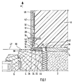
- Fig. 1 is a horizontal section. 1 shows a detail of a building wall 2, a detail of a built-in window opening of the building wall 2, fixed window frame 4, a section of an openable window sash 6, a section of a thermal insulation 8, a plaster finishing strip 10, and an end portion of a plaster layer 12.
- the arrow A marks the direction away from the building wall 2 to the outside.
- the thermal insulation 8 is mounted on the outside 14 of the building wall 2 and overlaps a piece of the window frame 4. Alternatively, you can think of the building wall 2 continued upward in Fig. 1, so that in this upwardly continued range in Fig. 1 left boundary of the building wall 2 represents the soffit surface of the window opening. In this case, the thermal insulation 8 may be mounted on the soffit surface.
- the thermal insulation 8 is typically made of foamed polystyrene or solidified into a plate-like structure mineral fibers.
- plastic pin 16 is not part of the plaster finishing strip 10 when it is delivered and is later in a first installation phase.
- the function of the pen 16 will be described in more detail below. For the description that follows, let's first think of pen 16 as non-existent.
- the cleaning edge strip has a base region 20, a containment region 22, an expansion strip 24, a cover region 26, a plastering leg 28, a plaster control region 34, a tab 30, and a reinforcement fabric section 32.
- the plaster finishing strip 10 (which for reasons of abbreviation is hereinafter referred to as "strip") is inserted into a gap 36 which extends between the outwardly facing surface 38 of the window frame 4 and the surface 38 facing the end surface 40 of the thermal insulation 8 is located.
- the gap 36 need not have a (measured horizontally) height H, which corresponds to the measured in the same direction height of the introduced into the gap 36 portion of the strip 10. If the height H of the gap 36 is less than the height of said part of the strip 10, this part of the strip 10 is forced into the gap 36 for installation; the thermal insulation 8 is yielding enough to allow this. If the height H of the gap 36 is greater than the said height of the part of the strip 10, this part of the strip 10 is installed so that it rests against the surface 38 of the window frame 4, so that a residual gap to the boundary 40 of the thermal insulation 8 remains ,
- the base portion 20 of the strip 10 has in the illustrated cross-section substantially the configuration of an angle profile. Assuming the coverage area 26 to the base area 20, the base area 20 has a channel-like profile.
- the locking portion 22 has a substantially wall-like configuration.
- the Einputzschenkel 28 protrudes in the direction of the surface 38 away from the rest of the strip 10 and is in the drawn installed state against the pointing to the left in Fig. 1 boundary surface 42 of the insulation 8.
- the plaster control region 34 extends substantially at 135 ° relative to the plaster leg 28 and substantially at 135 ° relative to the base wall 43 of the base region 20, which extends parallel to the outer surface 38 of the window frame 4.
- the blocking region 22 merges integrally into the free end of the cleaning end region 34 at its left-hand end in FIG. 1.
- the cleaning end region 34 is in the present Registration understood as part of the base area 20.
- the integral material transition between the end of the locking portion 22 and the end of the cleaning end portion 34 is made with a thin material thickness. Adjacent to this material region of thin material thickness, the right end of the tab 30 in FIG. 1 merges integrally into the left end region of the containment region 22. At the right end in FIG. 1, the containment region 22 is behind a corresponding projection 44 at the lower right end of the base region 20 locked.
- the expansion strip 24 creates a secure seal of the gap 36, which also contributes later changes in the height H of the gap 36 (eg, by shrinkage or movements of the window frame 4 under wind or by slamming the sash 6) elastic as it.
- the sealing effect is maintained by the continuing expansion tendency of the expansion strip 24 as it were with a certain bias.
- the bar 10 is connected to the thermal insulation 8 and thereby fixed in position.
- the Arm michsgewebeabites 32 lies along the boundary surface 42 of the thermal insulation 8. Partially overlapping herewith is another Arm michsgewebeabêt 46. Both Arm michsgewebeabitese 32 and 46 are spatulated by means not shown putty to the boundary surface 42.
- the plaster layer 12 is applied. If desired, for the steps of filling and applying the plaster layer 12, a reinforced fixation of the strip 10 to the thermal insulation 8 can be achieved by the pin 16 (actually several pins 16 along the length of the bar 10 distributed) by an opening in Einputzschenkel 28 is pushed through into the thermal insulation 8. After hardening of the spatula, but preferably before applying the plaster layer 12, the pin 16 can either be pulled out to the left or almost completely pushed into the heat insulation 8 to the right so that it is no longer visible in finished plaster layer 12.
- the coverage area 26 causes only a portion of the - measured in the direction of the height H of the gap 36 - height of the expansion strip 24 is visible in the fully installed state (ie after removal of the Einperr Suites 22) from the left in Fig. 1 end face of the expansion strip 24 ,
- the apparent height of the expansion strip 24 naturally depends on how much the expansion strip 24 has expanded.
- Fig. 1 also shows a protective film 46 which is temporarily glued to the outwardly directed and there provided with an adhesive layer surface of the tab 30.
- a gutter profiling 48 can be seen on the cleaning end region 34 and on a subsequent part of the height of the plastering leg 28 in order to provide increased adhesion for the plaster layer 12 there.
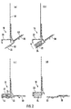
- Fig. 2 shows several phases of the production of the bar 10 (being reversed in comparison to Fig. 1 left and right).
- Sub-figure (a) shows the state after extrusion of the fuselage strip 10 and after applying an adhesive surface 50 on the tab 30, an adhesive strip 52 on the Einperr Society 22 and the welding of Arm michodersgewebeabitess 32.
- the sub-figure (b) shows a later phase, After the compressed expansion strip 24 has been placed on the base region 20 facing surface of the Einperr Schemes 22.
- the subfigure (c) shows a turn later phase in which the Einperr Scheme 22 has been pivoted together with the tab 30 in the clockwise direction and has been locked in the projection 44 with the base portion 20.
- the strip 10 is delivered and installed at a construction site, as drawn in Fig. 1.
- the adhesive strip 52 helps to temporarily fix the strip 10 to the outer surface 38 of the window frame 4 so that the filling can be applied more conveniently.
- the adhesive strip 52 is just dimensioned so that the Einperr Scheme 22 can be pulled out in the plastered state of the strip 10 without difficulty.
- the sub-figure (d) illustrates the final state after the Einperr Scheme 22 has been pulled out by means of the tab 30 and an expansion of the Expansiosstsammlungs 24 has taken place.
- the locking portion 22 may have a groove-like cross-section.
- the latching projection 44 would then be in the installed state a distance away from the outer surface 38 of the window frame 4, as well as the other end of the Einperr Schemes 22 (there either integral material transition or second latch). This alternative embodiment is particularly suitable when the containment area 22 is to be brought into the release state before the bar 10 is installed.
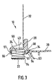
- FIG. 3 shows a plaster finishing strip 10 which, in some points, is deviating from the plaster finishing strip 10 according to FIGS. 1 and 2. Analogous components are denoted by the same reference numerals as in FIGS. 1 and 2. In comparison to FIG. 1, right and left are interchanged in FIG. 3. Building wall 2, thermal insulation 8, window frame 4 and plaster layer 12 are not drawn, although the drawn state with expanded expansion strip 24 results only in the finished installed state of the plaster finishing strip 10.
- the embodiment of the plaster finishing strip 10 according to FIG. 3 differs substantially from the exemplary embodiment of the plaster finishing strip 10 according to FIGS. 1 and 2 by the following:
- the plaster-limiting region 34 extends essentially at right angles to the plastering-in limb 28.
- a flexible protective lip 53 which has been produced by coextrusion with the hull of the plaster-finishing strip 10, is present on the plaster-cutting region 34.
- the Einperr Council 22 is a flat material strip of a material which differs from the material of the fuselage of the plaster finishing strip 10.
- the illustrated embodiment is a flat material strip of a nonwoven material.
- the nonwoven material located on a plastic carrier film 54, was adhered to the fuselage plaster molding 10, while the expansion strip 24 was in the trough-shaped installation space between the two side walls 51 and the base wall 43 of the base portion 20 in the compressed state.
- the bonding between the carrier film 54 and the base region 20 was on the end region of the left, angled leg 56 of the base region 20 in FIG. 3.
- On the right in FIG. 3 was the bond with a surface 58 which is coarse spoken - in the space between the right side wall 51 and the protective lip 52 is located.
- a first possibility is a severing of the carrier foil 54 just to the left of the expansion strip 24 and just to the right of the expansion strip 24.
- the two wedge-shaped spaces between (a) the leg 56 of the left side wall 51 and (b) the right side wall 51 and the area of Fuselage cleaning plaster 10 at the transition between the Einputzschenkel 28 and the Putzbegrenzungsschenkel 34 allows easy attachment of a knife and comfortable pulling the knife along the cleaning edge strip 10. Therefore, in Fig. 3 short lateral ends of the carrier film 54, which after cutting at the Locking 22 remain.
- the carrier foil 54 was and is glued in the region of the expansion strip 24 both with the expansion strip 24 and with the nonwoven material.
- a second possibility is to solve the two lateral bonds, namely at the end of the leg 56 and on the surface 58, z. B. by pulling away the edges of the carrier film 54 of said mating surfaces and "hanging" the wegholden edges on the expansion strip 24 and the nonwoven material of the Einperr Colours 22.
- the Wegziehbarkeit the edges of the carrier film 54 can be facilitated if there is an unprepared area which one can reach under the finger.
- a widened to the right training of the film so that it protrudes under the protective lip 52 is possible.
- the adhesion of the film to the leg 56 can be carried out so "weak” that you can pull out by pulling the film strip to the right in Fig. 3, the entire film strip between the bottom in Fig. 3 surface of the expansion strip 24 and the counter surface.
- Perforation lines on the left and / or to the right of the expansion strip 24 are also a possibility that facilitate the transfer of the strip of flat material in the release state. This applies to the removal of the plaster bordering strip 10 and for then-snagging on the plaster finishing strip 10.
- the combination of several options is possible, for. B. Removing a wiring right in Fig. 3 and perforation line on the left in Fig. 3rd
Abstract
Description
Gegenstand der Erfindung ist eine Putzabschlussleiste für eine Putzschicht auf einer Wärmedämmung, aufweisend folgende Merkmale:
- (a) einen Basisbereich, der einen Expansionsstreifen haltert;
- (b) einen Einsperrbereich, der im Einsperrzustand den Expansionsstreifen der Expansion hindert und der durch einen Verwender der Putzabschlussleiste in einen den Expansionsstreifen für die Expansion freigebenden Freigabezustand bringbar ist;
- (c) wobei die Putzabschlussleiste dafür ausgebildet ist, im eingebauten Zustand durch Verbindung mit der Wärmedämmung lagefixiert zu sein und beim Freigabezustand des Einsperrbereichs dem Expansionsstreifen die Expansion in Richtung von der Wärmedämmung weg und auf eine Gegenfläche zu zu ermöglichen.
- (a) a base region supporting an expansion strip;
- (b) a containment area which, in the containment state, prevents the expansion strip from expanding and which is engageable by a user of the trim end trim into a release state enabling the expander expansion stripe;
- (C) wherein the cleaning end strip is adapted to be fixed in position when installed by connection to the thermal insulation and the release state of Einperrbereichs the expansion strip to allow expansion in the direction of the heat insulation and on a counter surface.
Putzabschlussleisten sind in mannigfachen Ausführungen bekannt. Besonders häufig werden Putzabschlussleisten dort eingesetzt, wo eine Putzschicht auf der Aussenfläche einer Gebäudewand oder auf einer Laibungsfläche einer Fensteröffnung oder einer Türöffnung eines Gebäudes (bzw. auf eine auf der Aussenfläche oder der Laibungsfläche angebrachte Wärmedämmung) im Bereich eines Fensterrahmens oder eines Türrahmens endet. Mittels einer Putzabschlussleiste kann dafür gesorgt werden, dass die Putzschicht nicht unmittelbar an den Fensterrahmen oder Türrahmen heranreicht, sondern die entkoppelnd wirkende Putzabschlussleiste dazwischen sitzt. Es wird allerdings darauf hingewiesen, dass die erfindungsgemäße Putzabschlussleiste nicht nur für den Übergang zwischen der Putzschicht und einem Fensterrahmen oder einem Türrahmen brauchbar ist, sondern auch für andere Einbausituationen, wo die Putzschicht kurz vor einem anderen Bauteil endet. Insofern soll der Begriff "Gegenfläche" insbesondere alle bei Bauwerken infrage kommenden Bauteile umfassen, wobei Fensterrahmen oder Türrahmen bevorzugte Gegenflächen sind. Weitere Beispiele sind austretende Balken, Fensterbänke, eingebaute Briefkästen etc.Cleaning edges are known in manifold versions. Particularly often plaster finishing strips are used where a plaster layer ends on the outer surface of a building wall or on a reveal surface of a window opening or door opening of a building (or on a mounted on the outer surface or the soffit surface heat insulation) in the region of a window frame or a door frame. By means of a cleaning border can be ensured that the plaster layer does not reach directly to the window frame or door frame, but sitting in between the decoupling acting plaster finishing strip. It should be noted, however, that the plaster finishing strip according to the invention is useful not only for the transition between the plaster layer and a window frame or a door frame, but also for other installation situations where the plaster layer ends shortly before another component. In this respect, the term "counter surface" is intended to include in particular all of the components in question eligible components, with window frames or door frames are preferred mating surfaces. Further examples are emerging beams, window sills, built-in mailboxes, etc.
Der Basisbereich kann einen rinnen artigen Querschnitt haben. Andere Möglichkeiten sind wandartiger Querschnitt und Winkelprofil-artiger Querschnitt. Bei "rinnenartigem Querschnitt" kommt es vorzugsweise auf den Einbringungsraum für den Expansionsstreifen an. Es gibt Fälle, in denen der Einbauraum nicht nur durch den Basisbereich im engen Wortsinn bereitgestellt wird, sondern teilweise z. B. durch einen Abdeckbereich, einen Putzbegrenzungsbereich oder dgl. Für den "rinnenartigen Querschnitt" können derartige Bereiche dem Basisbereich zugerechnet werden.The base region may have a groove-like cross-section. Other possibilities are wall-like cross section and angle profile-like cross section. With "gutter-like cross-section", it is preferable for the insertion space for the expansion strip to arrive. There are cases in which the installation space is provided not only by the base area in the narrow sense of the word, but partially z. B. by a cover area, a plaster boundary area or the like. For the "groove-like cross section" such areas can be attributed to the base area.
Der Expansionsstreifen kann ein verzögert expansionsfähiger Schaumstoffstreifen sein. Derartige Schaumstoffstreifen sind bekannt. Die verzögerte Expansionsfähigkeit kann durch Tränkung mit einer Flüssigkeit hoher Viskosität erreicht werden. Wenn der Expansionsstreifen eine verzögerte Expansionsfähigkeit hat, läßt sich - je nach der sonstigen Art der Ausführung der Putzabschlussleiste - die Putzabschlussleiste besonders bequem einbauen. Es gibt aber durchaus Ausführungen der erfindungsgemäßen Putzabschlussleiste, bei denen Expansionsstreifen mit nicht-verzögerter -Expansion einsetzbar sind; ein Beispiel ist eine Putzabschlussleiste, bei welcher der Einsperrbereich nach dem Einbau der Putzabschlussleiste in den Freigabezustand gebracht wird.The expansion strip may be a delayed expandable foam strip. Such foam strips are known. The delayed expansion ability can be achieved by impregnation with a liquid of high viscosity. If the expansion strip has a delayed expansion capability, - depending on the other type of execution of the plaster finishing strip - can be particularly convenient to install the plaster finishing strip. However, there are quite some versions of the plaster finishing strip according to the invention, in which expansion strips can be used with non-delayed expansion; an example is a cleaning border, in which the Einperrbereich is brought into the release state after installation of the cleaning border.
"Bringen des Einsperrbereichs in den Freigabezustand" bedeutet in den meisten Fällen ein Wegtrennen des Einsperrbereichs von der restlichen Putzabschlussleiste. Es gibt aber auch Ausführungen, bei denen der Einsperrbereich auch im Freigabezustand praktisch vollständig oder teilweise an der Putzabschlussleiste verbleibt."Bringing the lock-in area into the release state" means in most cases a separation of the lock-in area from the rest of the cleaning trim strip. But there are also versions in which the Einperrbereich remains virtually completely or partially in the release state of the plaster finishing strip.
Vorzugsweise soll der Expansionsstreifen im fertigen eingebauten Zustand eine Abdichtung gegen Wind und Schlagregen liefern.Preferably, the expansion strip in the final installed state should provide a seal against wind and driving rain.
Die erfindungsgemäße Putzabschlussleiste ist insbesondere auch dann einsetzbar, wenn kein (dauerfestes) Ankleben an die Gegenfläche möglich ist, z. B. im Fall des Vorhandenseins einer selbstreinigenden Farbe auf der Gegenfläche.The plaster finishing strip according to the invention is also used in particular when no (permanent) sticking to the counter surface is possible, for. In the case of the presence of a self-cleaning paint on the mating surface.
Die Putzabschlussleiste kann einen vorragenden Einputzschenkel zum Einbetten in die Putzschicht aufweisen. Eine Putzabschlussleiste mit einem vorragenden Einputzschenkel zeigt typischerweise eine besonders feste Verbindung zwischen der Wärmedämmung und der Putzabschlussleiste im eingebauten Zustand. Der Einputzschenkel kann eine Vorragerichtung haben, die im wesentlichen der Expansionsrichtung des Expansionsstreifens entgegengesetzt ist. Der Einputzschenkel kann eine die Haftung der Putzschicht erhöhende Rinnenprofilierung aufweisen.The plaster finishing strip may have a projecting Einputzschenkel for embedding in the plaster layer. A plaster finishing strip with a protruding Einputzschenkel typically shows a particularly strong connection between the thermal insulation and the plaster finishing strip in the installed state. The Einputzschenkel may have a Vorreagerichtung which is opposite to the expansion direction of the expansion strip substantially. The Einputzschenkel may have a the adhesion of the plaster layer increasing gutter profiling.
An der Putzabschlussleiste kann ein Armierungsgewebeabschnitt befestigt sein, der sich im eingebauten Zustand der Putzabschlussleiste entlang einer Fläche der Wärmedämmung erstreckt und mit dieser durch Spachtelung verbunden werden kann. Der Armierungsgewebeabschnitt kann an dem beschriebenen Einputzschenkel befestigt sein. Der Armierungsgewebeabschnitt kann durch Schweissung an der restlichen Putzabschlussleiste befestigt sein. Andere Arten der Befestigung sind möglich, insbesondere Klebung und Einklemmung.A reinforcing fabric section, which extends in the installed state of the plaster finishing strip along a surface of the thermal insulation and can be connected thereto by means of filling, can be fastened to the plaster finishing strip. The Armierungsgewebeabschnitt may be attached to the described Einputzschenkel. The Armierungsgewebeabschnitt may be secured by welding to the rest of the plaster finishing strip. Other types of attachment are possible, in particular adhesion and entrapment.
Der Einsperrbereich kann durch formschlüssige Rastung in dem Einsperrzustand gehalten sein. Das ist eine für die Herstellung günstige Ausführung. Außerdem ist es bei einer Rastung vergleichsweise unproblematisch möglich, den Einsperrbereich von dem Einsperrzustand in den Freigabezustand zu bringen.The lock-in area can be held in the lock-in state by positive latching. This is a cheap for the production. In addition, it is comparatively easy for a detent to bring the Einperrbereich of the lockout in the release state.
Es ist möglich, die Putzabschlussleiste so auszuführen, dass der Einsperrbereich integral in den Basisbereich übergeht. In diesem Fall kann man den Einsperrbereich gut in einstückiger Weise mit der restlichen Putzabschlussleiste fertigen. Eine mögliche Ausführungsform besteht darin, dass der Einsperrbereich - im Querschnitt gesehen - an einem Ende integral in den Basisbereich übergeht und an dem anderen Ende formschlüssig mit dem Basisbereich verrastet ist. Dies kombiniert gute Herstellbarkeit mit guter Überführbarkeit des Einsperrbereichs in den Freigabezustand.It is possible to carry out the cleaning end molding such that the locking region integrally merges into the base region. In this case, you can make the Einperrbereich well in one piece with the rest of cleaning plaster. One possible embodiment is that the locking region - seen in cross-section - integrally merges into the base region at one end and is positively locked to the base region at the other end. This combines good manufacturability with good transferability of the containment area into the release state.
Der Einsperrbereich kann im wesentlichen die Konfiguration einer Wand besitzen. Andere Möglichkeiten sind insbesondere ein rinnenartiger Querschnitt und ein Winkelprofil-artiger Querschnitt.The containment area can essentially have the configuration of a wall. Other possibilities are, in particular, a groove-like cross section and an angle profile-like cross section.
Die Putzabschlussleiste kann so ausgeführt sein, dass der Freigabezustand durch Entfernen des Einsperrbereichs von der Putzabschlussleiste, ehe sie eingebaut ist, erreichbar ist. Die Putzabschlussleiste kann alternativ so ausgeführt sein, dass der Freigabezustand durch Entfernen des Einsperrbereichs von der Putzabschlussleiste, nachdem sie eingebaut ist, erreichbar ist.The cleaning end strip can be designed such that the release state can be achieved by removing the locking area from the cleaning end strip before it is installed. Alternatively, the cleaning end strip may be configured so that the release state is achievable by removing the containment area from the cleaning end strip after it is installed.
Dem Einsperrbereich kann eine Lasche zugeordnet sein, wobei eine integrale Materialverbindung zwischen dem Einsperrbereich und dem Basisbereich durch Schwenken der Lasche auftrennbar ist. Anschließend kann die Lasche mitsamt dem Einsperrbereich von der restlichen Putzabschlussleiste weggezogen werden.The locking area may be associated with a tab, wherein an integral material connection between the Einperrbereich and the base area can be separated by pivoting the tab. Subsequently, the tab can be pulled away together with the Einperrbereich of the remaining plaster finishing strip.
Die Lasche kann einen Kleberstreifen aufweisen, mittels welchem eine Schutzfolie, die ein Verschmutzen des nicht einzuputzenden Teils der Putzabschlussleiste und ein Verschmutzen des Fensterrahmens oder des Türrahmens mit dem Putzschichtmaterial verhindert, an der Putzabschlussleiste befestigbar ist. Im Fall eines Fensterrahmens oder eines Türrahmens kann die Schutzfolie die Fensterrahmenöffnung oder die Türrahmenöffnung insgesamt überspannen.The tab may have an adhesive strip, by means of which a protective film, which prevents fouling of the non-einzuputzenden part of Putzabschlussleiste and contamination of the window frame or the door frame with the plaster layer material, is attachable to the plaster finishing strip. In the case of a window frame or door frame, the protective film may span the window frame opening or the door frame opening as a whole.
Der Einsperrbereich kann auf seiner dem Expansionsstreifen abgewandten Seite einen Kleberstreifen aufweisen, mittels welchem die Putzabschlussleiste temporär an der genannten Gegenfläche lagefixierbar ist. Es erleichtert den Einbau der Putzabschlussleiste, wenn diese zunächst temporär an der Gegenfläche lagefixiert wird, ggf. der Armierungsgewebeabschnitt auf der Wärmedämmung angespachtelt wird, anschließend die Putzschicht aufgebracht und dadurch die Putzanschlussleiste abschließend an der Wärmedämmung lagefixiert wird, und schließlich der Einsperrbereich durch Entfernen von der restlichen Putzabschlussleiste in eine den Expansionsstreifen freigebenden Zustand gebracht wird.The Einperrbereich may have on its side facing away from the expansion strip an adhesive strip, by means of which the plaster finishing strip is temporarily fixed in position on said mating surface. It facilitates the installation of the plaster border, if this is temporarily fixed in position on the mating surface, if necessary, the Armierungsgewebeabschnitt is spatulated on the insulation, then applied the plaster layer and thereby the plaster connection strip is finally fixed in position on the insulation, and finally the Einperrbereich by removing the remaining plaster finishing strip is brought into a release strip releasing state.
Die Putzabschlussleiste kann einen Abdeckungsbereich auf derjenigen Seite des Expansionsstreifens aufweisen, die im eingebauten Zustand der Putzabschlussleiste einem Betrachter zugewandt ist. Auf diese Weise sieht ein Betrachter nicht mehr die gesamte Höhe des expandierten Expansionsstreifens, sondern nur noch einen Teil dieser Höhe. Die Putzabschlussleiste kann eine flexible Schutzlippe auf derjenigen Seite des Expansionsstreifens aufweisen, die im eingebauten Zustand der Putzabschlussleiste einem Betrachter zugewandt ist. Die Schutzlippe stellt ebenfalls eine optische Abdeckung des ggf. expandierten Expansionsstreifens dar. Die Schutzlippe kann wegen ihrer Flexibilität in größerer Höhe als der beschriebene Abdeckungsbereich ausgeführt werden, so dass sie auch nach erheblicher Expansion des Expansionsstreifens noch an der Gegenfläche anliegt. Die Schutzlippe kann den Expansionsstreifen gegen Verschmutzung und unmittelbare Regeneinwirkung schützen.The plaster finishing strip can have a covering area on that side of the expansion strip which, in the installed state of the plaster finishing strip, faces an observer. In this way, a viewer no longer sees the entire height of the expanded expansion strip, but only a part of this height. The plaster finishing strip can be a flexible protective lip have on that side of the expansion strip, which faces a viewer in the installed state of the plaster finishing strip. The protective lip also represents an optical cover of the optionally expanded expansion strip. The protective lip can be performed because of their flexibility at a higher height than the coverage area described, so that it still rests on the counter surface even after considerable expansion of the expansion strip. The protective lip can protect the expansion strip against contamination and direct rain.
Die Putzabschlussleiste kann einen im Lieferzustand weggespreizten Vorsprung haben und kann, ggf. nach elastischem Herandrücken des Vorsprungs in Richtung zu der restlichen Putzabschlussleiste hin, in einen Spalt zwischen der Wärmedämmung und der genannten Gegenfläche einschiebbar sein. Bei genügendem Wegspreizmaß des Vorsprungs und bei hinreichend engem Spalt kann sich ein Einklemmeffekt für die Putzabschlussleiste ergeben. Man kann die Ausführung so wählen, dass sich mindestens temporär eine Lagefixierung der Putzabschlussleiste ergibt oder die Einklemmung zur Lagefixierung beiträgt.The plaster finishing strip can have a projection spread apart in the delivery state and, if necessary after elastic pressing of the projection in the direction of the remaining plaster finishing strip, can be inserted into a gap between the thermal insulation and the counter surface mentioned. With sufficient Wegspreizmaß the projection and a sufficiently narrow gap may result in a pinching effect for the plaster finish. You can choose the design so that at least temporarily results in a positional fixation of the plaster finish or the pinching contributes to fixing the position.
Die Putzabschlussleiste kann zwischen der der genannten Gegenfläche abgewandten Rückseite des Expansionsstreifens und dem Basisbereich ein Vorspannelement für die Bewegung des Expansionsstreifens in Expansionsrichtung aufweisen. Das Vorspannelement kann insbesondere ein Metallstreifen oder ein Kunststoffstreifen sein, der im Einsperrzustand des Expansionsstreifens zwischen dem Expansionsstreifen und dem Basisbereich elastisch deformiert ist.The cleaning end strip can have a biasing element for the movement of the expansion strip in the expansion direction between the rear side of the expansion strip facing away from the counter surface and the base area. In particular, the biasing member may be a metal strip or a plastic strip which is elastically deformed in the locking state of the expansion strip between the expansion strip and the base region.
Der Einsperrbereich kann einen Flachmaterialstreifen aufweisen, der im Einsperrzustand an der restlichen Putzabschlussleiste befestigt ist. Dieser Flachmaterialstreifen kann sich materialmäßig von dem Material des Rumpfes der Putzabschlussleiste unterscheiden.The Einperrbereich may have a flat material strip, which is fastened in the lock-in state on the remaining plaster finishing strip. This flat material strip may differ materially from the material of the hull of the plaster border.
Der Flachmaterialstreifen kann insbesondere mit einem Vliesmaterial oder mit einer Kunststofffolie oder mit Papier aufgebaut sein. Wenn der Flachmaterialstreifen, um den Freigabezustand zu erreichen, von der restlichen Putzabschlussleiste weggetrennt werden soll, ist es günstig, ihn aus einem verrottungsfähigen Material, insbesondere verrottungsfähigem Vliesmaterial, verrottungsfähiger Kunststofffolie oder Papier, aufzubauen. Dann kann er auf der Baustelle aufwandsarm entsorgt werden. Typische verrottungsfähige Materialien verrotten innerhalb einiger Monate im Erdreich.The flat material strip may in particular be constructed with a nonwoven material or with a plastic film or with paper. When the sheet of flat material is to be separated away from the remainder of the plaster finishing strip in order to reach the release state, it is favorable to use it from a decomposable material, in particular rotting nonwoven material, rotting plastic film or paper. Then it can be disposed of at the construction site with little effort. Typical rotable materials rot within a few months in the ground.
Der Flachmaterialstreifen kann durch Schweissung, Klebung oder Klemmung an der restlichen Putzabschlussleiste befestigt sein.The flat material strip can be fastened by welding, gluing or clamping to the remaining plaster finishing strip.
Weiterer Gegenstand der Erfindung ist die Verwendung der in der vorliegenden Anmeldung offenbarten Putzabschlussleiste am Übergang zwischen einem Fensterrahmen oder einem Türrahmen und der Wärmedämmung, die auf der Aussenseite einer Gebäudewand oder auf der Laibungsfläche der Fensteröffnung bzw. Türöffnung eines Gebäudes angebracht ist.Another object of the invention is the use of the disclosed in the present application cleaning border at the transition between a window frame or a door frame and the thermal insulation, which is mounted on the outside of a building wall or on the soffit surface of the window opening or door opening of a building.
Die erfindungsgemäße Putzabschlussleiste kann, gewünschtenfalls mit Ausnahme des Armierungsgewebeabschnitts und gewünschtenfalls mit Ausnahme des Expansionsstreifens, aus Kunststoff bestehen. Polyvinylchlorid (PVC), Polystyrol (PS) und Polypropylen (PP) gehören zu den geeigneten Kunststoffen. Ggf. mit Ausnahme des Armierungsgewebeabschnitts und ggf. mit Ausnahme des Expansionsstreifens und ggf. mit Ausnahme der genannten Kleberstreifen läßt sich die Putzabschlussleiste in derartiger Weise ausführen, dass sie durch Kunststoffextrusion herstellbar ist.The plaster finishing strip according to the invention can, if desired, with the exception of the Armierungsgewebeabschnitts and, if desired, with the exception of the expansion strip, made of plastic. Polyvinyl chloride (PVC), polystyrene (PS) and polypropylene (PP) are among the suitable plastics. Possibly. With the exception of the Armierungsgewebeabschnitts and possibly with the exception of the expansion strip and possibly with the exception of said adhesive strips, the cleaning border strip can run in such a way that it can be produced by plastic extrusion.
Die Erfindung wird nachfolgend anhand eines zeichnerisch dargestellten Ausführungsbeispiels noch näher erläutert. Es zeigt:
- Fig. 1
- eine Putzabschlussleiste im Querschnitt, und zwar im eingebauten Zustand aber vor Wegnahme eines Einsperrbereichs;
- Fig. 2
- die Putzabschlussleiste von Fig. 1 zur Veranschaulichung mehrerer Phasen der Herstellung und zur Veranschaulichung des expandierten Zustands eines Expansionsstreifens;
- Fig. 3
- eine andere Putzabschlussleiste im Querschnitt, und zwar nach Expansion des Expansionsstreifens.
- Fig. 1
- a plaster border in cross-section, in the installed state but before removal of a Einperrbereichs;
- Fig. 2
- FIG. 1 shows the plaster finishing strip of FIG. 1 for illustrating a plurality of production stages and for illustrating the expanded state of an expansion strip; FIG.
- Fig. 3
- another cleaning border in cross section, after expansion of the expansion strip.
Fig. 1 ist ein horizontaler Schnitt. In Fig. 1 sieht man einen Ausschnitt einer Gebäudewand 2, einen Ausschnitt eines in eine Fensteröffnung der Gebäudewand 2 eingebauten, fest stehenden Fensterrahmens 4, einen Ausschnitt eines öffenbaren Fensterflügels 6, einen Ausschnitt einer Wärmedämmung 8, eine Putzabschlussleiste 10, und einen Endbereich einer Putzschicht 12. Mit dem Pfeil A ist die Richtung von der Gebäudewand 2 weg nach außen markiert. Die Wärmedämmung 8 ist auf der Aussenseite 14 der Gebäudewand 2 angebracht und übergreift ein Stück weit den Fensterrahmen 4. Alternativ kann man sich die Gebäudewand 2 nach oben in Fig. 1 fortgesetzt denken, so dass in diesem nach oben fortgesetzten Bereich die in Fig. 1 linke Begrenzung der Gebäudewand 2 die Laibungsfläche der Fensteröffnung darstellt. In diesem Fall kann die Wärmedämmung 8 auf der Laibungsfläche angebracht sein. Die Wärmedämmung 8 besteht typischwerweise aus geschäumtem Polystyrol oder aus zu einem plattenartigen Gebilde verfestigten Mineralfasern.Fig. 1 is a horizontal section. 1 shows a detail of a
Der in Fig. 1 eingezeichnete Kunststoffstift 16 ist nicht Bestandteil der Putzabschlussleiste 10, wenn diese angeliefert wird und sich später in einer ersten Einbauphase befindet. Die Funktion des Stifts 16 wird weiter unten noch genauer beschrieben. Für die jetzt anschließende Beschreibung möge man sich zunächst den Stift 16 als nicht vorhanden vorstellen.The plotted in Fig. 1
Die Putzabschlussleiste besitzt einen Basisbereich 20, einen Einsperrbereich 22, einen Expansionsstreifen 24, einen Abdeckungsbereich 26, einen Einputzschenkel 28, einen Putzbegrenzungsbereich 34, eine Lasche 30, und einen Armierungsgewebeabschnitt 32.The cleaning edge strip has a
Nachdem der Fensterrahmen 4 in die Fensteröffnung der Gebäudewand 2 eingebaut worden ist und nachdem die Wärmedämmung 8 angebracht worden ist, wird die Putzabschlussleiste 10 (die im folgenden aus Abkürzungsgründen nur noch als "Leiste" bezeichnet wird) in einen Spalt 36 eingesetzt, der sich zwischen der nach außen gewandten Oberfläche 38 des Fensterrahmens 4 und der dieser Oberfläche 38 zugewandten Endfläche 40 der Wärmedämmung 8 befindet. Der Spalt 36 muss nicht eine (waagerecht gemessene) Höhe H haben, die der in gleicher Richtung gemessenen Höhe des in den Spalt 36 eingebrachten Teils der Leiste 10 entspricht. Wenn die Höhe H des Spalts 36 geringer ist als die Höhe des genannten Teils der Leiste 10, wird zum Einbau dieser Teil der Leiste 10 in den Spalt 36 hinein gezwängt; die Wärmedämmung 8 ist nachgiebig genug, um das zu erlauben. Wenn die Höhe H des Spalts 36 größer ist als die genannte Höhe des Teils der Leiste 10, wird dieser Teil der Leiste 10 so eingebaut, dass er an der Oberfläche 38 des Fensterrahmens 4 anliegt, so dass ein Restspalt zur Begrenzung 40 der Wärmedämmung 8 verbleibt.After the
Der Basisbereich 20 der Leiste 10 hat im gezeichneten Querschnitt im wesentlichen die Konfiguration eines Winkelprofils. Wenn man den Abdeckungsbereich 26 dem Basisbereich 20 zurechnet, hat der Basisbereich 20 ein rinnenartiges Profil. Der Einsperrbereich 22 hat im wesentlichen eine wandartige Konfiguration. Der Einputzschenkel 28 ragt in Richtung von der Oberfläche 38 weg von der restlichen Leiste 10 vor und liegt im gezeichneten eingebauten Zustand gegen die nach links in Fig. 1 weisende Begrenzungsfläche 42 der Wärmedämmung 8 an. Der Putzbegrenzungsbereich 34 verläuft im wesentlichen unter 135° relativ zu dem Einputzschenkel 28 und im wesentlichen unter 135° relativ zu der Basiswand 43 des Basisbereichs 20, die parallel zur Außenfläche 38 des Fensterrahmens 4 verläuft.The
Der Einsperrbereich 22 geht an seinem in Fig. 1 linken Ende integral in das freie Ende des Putzendbereichs 34 über. Der Putzendbereich 34 wird in der vorliegenden Anmeldung als Bestandteil des Basisbereichs 20 verstanden. Der integrale Materialübergang zwischen dem Ende des Einsperrbereichs 22 und dem Ende des Putzendbereichs 34 ist mit dünner Materialdicke ausgeführt. Benachbart diesem Materialbereich dünner Materialdicke geht das in Fig. 1 rechte Ende der Lasche 30 integral über in den linken Endbereich des Einsperrbereichs 22. Am in Fig. 1 rechten Ende ist der Einsperrbereich 22 hinter einem entsprechenden Vorsprung 44 am rechten - unteren Ende des Basisbereichs 20 verrastet. Wenn man die Lasche 30, ausgehend von dem in Fig. 1 gezeichneten Zustand, im Uhrzeigersinn nach außen schwenkt, bricht der geschilderte Bereich dünner Materialdicke zwischen dem Putzendbereich 34 und dem Einsperrbereich 22; die Lasche 30 und der Einsperrbereich 22 bleiben aber miteinander verbunden. Jetzt kann durch Ziehen an der Lasche 30 nach links in Fig. 1 der Einsperrbereich 22 aus der Verrastung hinter dem Vorsprung 44 herausgezogen und insgesamt nach links in Fig. 1 von der restlichen Leiste 10 entfernt werden. Der Expansionsstreifen 24, der sich bisher zwischen der Basiswand 43 des Basisbereichs 20 und dem Einsperrbereich 22 befand, kann sich nun in Richtung auf die Außenfläche 38 des Fensterrahmens 4 hin ausdehnen. Auf diese Weise schafft der Expansionsstreifen 24 eine sichere Abdichtung des Spalts 36, die auch spätere Änderungen in der Höhe H des Spalts 36 (z.B. durch Schwindungsvorgänge oder durch Bewegungen des Fensterrahmens 4 unter Windeinfluß oder durch Zuschlagen des Fensterflügels 6) gleichsam elastisch mitmacht. Die Dichtungswirkung wird durch die weiter bestehende Expansionstendenz des Expansionsstreifens 24 gleichsam mit gewisser Vorspannung aufrechterhalten.The blocking
Bevor allerdings der Einsperrbereich 22 auf die beschriebene Weise herausgezogen wird, wird die Leiste 10 mit der Wärmedämmung 8 verbunden und dadurch lagefixiert. Der Armierungsgewebeabschnitt 32 liegt entlang der Begrenzungsfläche 42 der Wärmedämmung 8. Teilweise überlappend hiermit befindet sich ein weiterer Armierungsgewebeabschnitt 46. Beide Armierungsgewebeabschnitte 32 und 46 werden mit Hilfe von nicht eingezeichneter Spachtelmasse an die Begrenzungsfläche 42 angespachtelt. Nach dem Erhärten der Spachtelmasse wird die Putzschicht 12 aufgebracht. Gewünschtenfalls kann für die Arbeitsschritte des Anspachtelns und des Aufbringens der Putzschicht 12 eine verstärkte Fixierung der Leiste 10 an der Wärmedämmung 8 dadurch erreicht werden, dass der Stift 16 (in Wirklichkeit mehrere Stifte 16 längs der Länge der Leiste 10 verteilt) durch eine Öffnung im Einputzschenkel 28 hindurch in die Wärmedämmung 8 hineingedrückt wird. Nach dem Erhärten der Spachtelung, aber am besten vor dem Aufbringen der Putzschicht 12, kann der Stift 16 entweder nach links herausgezogen oder nach rechts quasi vollständig in die Wärmedämmung 8 hineingedrückt werden, so dass er bei fertiger Putzschicht 12 nicht mehr sichtbar ist.However, before the locking
Der Abdeckungsbereich 26 bewirkt, dass im fertig eingebauten Zustand (d.h. nach Entfernung des Einsperrbereichs 22) von der in Fig. 1 linken Endfläche des Expansionsstreifens 24 nur ein Teil der - in Richtung der Höhe H des Spalts 36 gemessenen - Höhe des Expansionsstreifens 24 sichtbar ist. Die sichtbare Höhe des Expansionsstreifens 24 hängt naturgemäß davon ab, wie stark sich der Expansionsstreifen 24 expandiert hat.The
In Fig. 1 erkennt man außerdem eine Schutzfolie 46, die temporär auf die nach außen gerichtete und dort mit einer Kleberschicht versehene Fläche der Lasche 30 aufgeklebt ist. Schließlich erkennt man eine Rinnenprofilierung 48 am Putzendbereich 34 und auf einem anschließenden Teil der Höhe des Einputzschenkels 28, um dort eine verstärkte Haftung für die Putzschicht 12 zu schaffen.In Fig. 1 also shows a
Durch Fig. 2 sind mehrere Phasen der Herstellung der Leiste 10 veranschaulicht (wobei im Vergleich zu Fig. 1 links und rechts vertauscht sind). Die Teilfigur (a) zeigt den Zustand nach Extrusion der Rumpf-Leiste 10 und nach Aufbringen einer Kleberfläche 50 auf die Lasche 30, eines Kleberstreifens 52 auf den Einsperrbereich 22 und dem Anschweißen des Armierungsgewebeabschnitts 32. Die Teilfigur (b) zeigt eine spätere Phase, nachdem der komprimierte Expansionsstreifen 24 auf die dem Basisbereich 20 zugewandte Fläche des Einsperrbereichs 22 aufgelegt worden ist. Die Teilfigur (c) zeigt eine wiederum spätere Phase, in welcher der Einsperrbereich 22 mitsamt der Lasche 30 im Uhrzeigersinn verschwenkt und bei dem Vorsprung 44 mit dem Basisbereich 20 verrastet worden ist. In diesem Zustand wird die Leiste 10 an einer Baustelle angeliefert und eingebaut, wie in Fig. 1 gezeichnet. Der Kleberstreifen 52 hilft dabei für eine temporäre Fixierung der Leiste 10 an der Außenfläche 38 des Fensterrahmens 4, damit die Spachtelung bequemer aufgebracht werden kann. Der Kleberstreifen 52 ist gerade so dimensioniert, dass der Einsperrbereich 22 im eingeputzten Zustand der Leiste 10 ohne Schwierigkeiten herausgezogen werden kann.By Fig. 2, several phases of the production of the
Die Teilfigur (d) veranschaulicht den Schlusszustand, nachdem der Einsperrbereich 22 mit Hilfe der Lasche 30 herausgezogen worden ist und eine Expansion des Expansiosstreifens 24 stattgefunden hat.The sub-figure (d) illustrates the final state after the
Statt des Abdeckungsbereichs 26 kann man auch eine coextrudierte flexible Schutzlippe vorsehen, die eine größere Höhe als der Abdeckungsbereich 26 haben kann. Statt der wandartigen Konfiguration kann der Einsperrbereich 22 einen rinnenartigen Querschnitt haben. Der Verrastungsvorsprung 44 würde dann im eingebauten Zustand ein Stück entfernt von der Außenfläche 38 des Fensterrahmens 4 liegen, ebenso das andere Ende des Einsperrbereichs 22 (dort entweder integraler Materialübergang oder zweite Verrastung). Diese alternative Ausführungsform ist besonders geeignet, wenn der Einsperrbereich 22 in den Freigabezustand gebracht werden soll, ehe die Leiste 10 eingebaut wird.Instead of the
Bei der ersten Phase des Einbauens der Leiste 10 kann man auch so vorgehen, dass man auf die in Fig. 1 rechte Seite des Einputzschenkels 28 und ggf. auch auf die in Fig. 1 obere Seite der Basiswand 44 des Basisbereichs 20 Spachtelmasse gibt und dann durch Andrücken der Leiste 10 an die Wärmedämmung 8 eine erste, vorläufige Fixierung der Leiste 10 an der Wärmedämmung 8 erreicht. Dies erleichtert die nachfolgenden Arbeitsschritte.In the first phase of installation of the
Fig. 3 zeigt eine Putzabschlussleiste 10, die in einigen Punkten abweichend von der Putzabschlussleiste 10 gemäß Fig. 1 und Fig. 2 ausgebildet ist. Analoge Bestandteile werden mit den gleichen Bezugsziffern wie in Fig. 1 und Fig. 2 bezeichnet. Im Vergleich zu Fig. 1 sind bei Fig. 3 rechts und links vertauscht. Gebäudewand 2, Wärmedämmung 8, Fensterrahmen 4 und Putzschicht 12 sind nicht gezeichnet, obwohl sich der gezeichnete Zustand mit expandiertem Expansionsstreifen 24 erst im fertig eingebauten Zustand der Putzabschlussleiste 10 ergibt.FIG. 3 shows a
Die Ausführungsform der Putzabschlussleiste 10 gemäß Fig. 3 unterscheidet sich im Wesentlichen von dem Ausführungsbeispiel der Putzabschlussleiste 10 gemäß Fig. 1 und Fig. 2 durch Folgendes:The embodiment of the
Es gibt zwei seitliche Begrenzungswände 51, zwischen denen der Expansionsstreifen 24 sitzt und die man als Bestandteil des Basisbereichs 20 auffassen kann. Die in Fig. 3 rechte Seitenwand 51 erinnert zwar an den Abdeckungsbereich 26 von Fig. 1, hat in Fig. 3 aber keine Abdeckungsfunktion. Der Putzbegrenzungsbereich 34 verläuft im Wesentlichen rechtwinklig zum Einputzschenkel 28. An dem Putzbegrenzungsbereich 34 ist eine flexible Schutzlippe 53 vorhanden, die durch Coextrusion mit dem Rumpf der Putzabschlussleiste 10 hergestellt worden ist.There are two
Ein besonders prominenter Unterschied zur Putzabschlussleiste 10 von Fig. 1 ist die Ausführung des Einsperrbereichs 22. Der Einsperrbereich 22 ist ein Flachmaterialstreifen aus einem Material, welches sich vom Material des Rumpfes der Putzabschlussleiste 10 unterscheidet. Im gezeichneten Ausführungsbeispiel handelt es sich um einen Flachmaterialstreifen aus einem Vliesmaterial. Im gezeichneten Ausführungsbeispiel war das Vliesmaterial, befindlich auf einer Kunststoff-Trägerfolie 54, an die Rumpf-Putzabschlussleiste 10 angeklebt worden, während sich der Expansionsstreifen 24 im komprimierten Zustand in dem rinnenförmigen Einbauraum zwischen den zwei Seitenwänden 51 und der Basiswand 43 des Basisbereichs 20 befand. Links in Fig. 3 war die Verklebung zwischen der Trägerfolie 54 und dem Basisbereich 20 auf dem Endbereich des in Fig. 3 linken, abgewinkelten Schenkels 56 des Basisbereichs 20. Rechts in Fig. 3 war die Verklebung mit einer Fläche 58, die sich - grob gesprochen - im Raum zwischen der rechten Seitenwand 51 und der Schutzlippe 52 befindet.A particularly prominent difference to the
Um den Einsperrbereich 22 in den Freigabezustand zu überführen (was zeitlich vor der in Fig. 3 gezeigten Situation erfolgt ist), gibt es eine Reihe von Möglichkeiten. Eine erste Möglichkeit ist ein Durchtrennen der Trägerfolie 54 knapp links neben dem Expansionsstreifen 24 und knapp rechts neben dem Expansionsstreifen 24. Die zwei keilförmigen Räume zwischen (a) dem Schenkel 56 der linken Seitenwand 51 und (b) der rechten Seitenwand 51 und dem Bereich des Rumpfes der Putzabschlussleiste 10 am Übergang zwischen dem Einputzschenkel 28 und dem Putzbegrenzungsschenkel 34 ermöglicht ein bequemes Ansetzen eines Messers und bequemes Ziehen des Messers längs der Putzabschlussleiste 10. Deshalb sieht man in Fig. 3 kurze seitliche Enden der Trägerfolie 54, die nach dem Durchschneiden an dem Einsperrbereich 22 verblieben sind. Die Trägerfolie 54 war und ist im Bereich des Expansionsstreifens 24 sowohl mit dem Expansionsstreifen 24 als auch mit dem Vliesmaterial verklebt.In order to bring the lock-in
Eine zweite Möglichkeit besteht darin, die zwei seitlichen Verklebungen, nämlich am Ende des Schenkels 56 und an der Fläche 58, zu lösen, z. B. durch Wegziehen der Ränder der Trägerfolie 54 von den genannten Gegenflächen und "Hängenlassen" der weggezogenen Ränder an dem Expansionsstreifen 24 bzw. dem Vliesmaterial des Einsperrbereichs 22. Die Wegziehbarkeit der Ränder der Trägerfolie 54 läßt sich erleichtern, wenn sich dort jeweils ein unangeklebter Bereich befindet, den man mit dem Finger untergreifen kann.A second possibility is to solve the two lateral bonds, namely at the end of the
Statt des beschriebenen Vliesmaterials kann man insbesondere auch einen Kunststofffolienstreifen oder einen Papierstreifen vorsehen. Statt der beschriebenen Verklebung kann insbesondere auch einen Verschweißung oder eine Verklemmung mit dem Rumpf der Putzabschlussleiste 10 vorgesehen sein.In particular, instead of the described nonwoven material, it is also possible to provide a plastic film strip or a paper strip. Instead of the described bonding, in particular, a weld or a jamming with the body of the
Die im Zusammenhang mit Fig. 3 und kurz zuvor in Abwandlungen beschriebenen Ausführungsformen waren so, dass der Einsperrbereich 22 vor dem Anbringen der Putzanschlussleiste 10 an der Wärmedämmung 8 in den Freigabezustand gebracht wurde. Es sind demgegenüber alternative Ausführungsformen möglich, bei denen der (aus einem anderen Material als der Rumpf der Putzabschlussleiste 10) bestehende Flachmaterialstreifen/Einsperrbereich 22 nach der Befestigung der Putzabschlussleiste 10 an der Wärmedämmung 8 in den Freigabezustand gebracht bzw. (gänzlich oder teilweise) von der restlichen Putzabschlussleiste 10 entfernt wird. Als Beispiel möge man sich die Ausführungsform gemäß Fig. 3 vor Augen halten, wenn der Flachmaterialstreifen aus einer Kunststofffolie besteht, welche nicht an dem Expansionsstreifen 24 festgeklebt ist. Dann kann man bei eingebauter Putzabschlussleiste 10 die Schutzlippe 52 anheben und darunter greifend den rechten Kleberand der Folie an der Fläche 58 lösen. Eine nach rechts verbreiterte Ausbildung der Folie, so dass sie unter der Schutzlippe 52 herausragt, ist möglich. Die Verklebung der Folie an dem Schenkel 56 kann so "schwach" ausgeführt werden, dass man durch Ziehen an dem Folienstreifen nach rechts in Fig. 3 den gesamten Folienstreifen zwischen der in Fig. 3 unteren Oberfläche des Expansionsstreifens 24 und der Gegenfläche herausziehen kann.The embodiments described in connection with FIG. 3 and just before in modifications were such that the locking
Perforationslinien links und/oder rechts neben dem Expansionsstreifen 24 sind auch eine Möglichkeit, die das Überführen des Flachmaterialstreifens in den Freigabezustand erleichtern. Das gilt für das Entfernen von der Putzabschlussleiste 10 und für Danach-Hängenbleiben an der Putzabschlussleiste 10. Auch die Kombination mehrerer Möglichkeiten ist möglich, z. B. Abziehen von einer Verkabelung rechts in Fig. 3 und Perforationslinie links in Fig. 3.Perforation lines on the left and / or to the right of the
Außerdem sieht man in Fig. 3 eine beispielhafte Ausführung eines weggespreizten Vorsprungs 58.In addition, one can see in Fig. 3 an exemplary embodiment of a weggespreizten projection 58th
Claims (26)
dadurch gekennzeichnet, dass der Basisbereich (20) einen rinnenartigen Querschnitt hat.Cleaning edge strip according to claim 1,
characterized in that the base region (20) has a groove-like cross-section.
dadurch gekennzeichnet, dass der Expansionsstreifen (24) ein verzögert expansionsfähiger Schaumstoffstreifen ist.Cleaning edge strip according to claim 1 or 2,
characterized in that the expansion strip (24) is a delayed expandable foam strip.
dadurch gekennzeichnet, dass sie einen vorragenden Einputzschenkel (28) zum Einbetten in die Putzschicht (12) aufweist.Cleaning end strip according to one of claims 1 to 3,
characterized in that it comprises a projecting Einputzschenkel (28) for embedding in the plaster layer (12).
dadurch gekennzeichnet, dass der Einputzschenkel (28) eine Vorragerichtung hat, die im wesentlichen der Expansionsrichtung des Expansionsstreifens (24) entgegengesetzt ist.Cleaning edge strip according to claim 4,
characterized in that the Einputzschenkel (28) has a Vorreagerichtung which is opposite to the expansion direction of the expansion strip (24) substantially opposite.
dadurch gekennzeichnet, dass der Einputzschenkel (28) eine die Haftung der Putzschicht (12) erhöhende Rinnenprofilierung (46) aufweist.Cleaning edge strip according to claim 4 or 5,
characterized in that the Einputzschenkel (28) has a the adhesion of the plaster layer (12) increasing trough profiling (46).
dadurch gekennzeichnet, dass an der Putzabschlussleiste (10) ein Armierungsgewebeabschnitt (32), der sich im eingebauten Zustand der Putzabschlussleiste (12) entlang einer Fläche der Wärmedämmung (8) erstreckt und durch Spachtelung mit dieser verbunden werden kann, befestigt ist.Cleaning edge strip according to one of claims 1 to 6,
characterized in that on the plaster finishing strip (10) a Armierungsgewebeabschnitt (32) which extends in the installed state of the plaster finishing strip (12) along a surface of the thermal insulation (8) and can be connected by filling with this is attached.
dadurch gekennzeichnet, dass der Armierungsgewebeabschnitt (32) durch Schweißung an dem Einputzschenkel (28) befestigt ist.Cleaning edge strip according to claim 7,
characterized in that the Armierungsgewebeabschnitt (32) is fixed by welding to the Einputzschenkel (28).
dadurch gekennzeichnet, dass der Einsperrbereich (22) durch formschlüssige Rastung in dem Einsperrzustand gehalten ist.Cleaning end strip according to one of claims 1 to 8,
characterized in that the Einperrbereich (22) is held by positive locking in the lock-in state.
dadurch gekennzeichnet, dass der Einsperrbereich (22) integral in den Basisbereich (20) übergeht.Cleaning end strip according to one of claims 1 to 9,
characterized in that the locking portion (22) merges integrally with the base portion (20).
dadurch gekennzeichnet, dass der Einsperrbereich (22) - im Querschnitt gesehen - an einem Ende integral in den Basisbereich (20) übergeht und an dem anderen Ende formschlüssig mit dem Basisbereich (20) verrastet ist.Cleaning end strip according to claims 9 and 10,
characterized in that the Einperrbereich (22) - seen in cross section - integrally merges at one end in the base region (20) and is positively locked at the other end to the base region (20).
dadurch gekennzeichnet, dass der Einsperrbereich (22) im Wesentlichen die Konfiguration einer Wand besitzt.Cleaning end strip according to one of claims 1 to 11,
characterized in that the locking portion (22) has substantially the configuration of a wall.
dadurch gekennzeichnet, dass der Einsperrbereich (22) im Wesentlichen einen rinnenartigen Querschnitt besitzt.Cleaning end strip according to one of claims 1 to 11,
characterized in that the Einperrbereich (22) has a groove-like cross-section substantially.
dadurch gekennzeichnet, dass der Freigabezustand durch Entfernen des Einsperrbereichs (22) von der Putzabschlussleiste (10), ehe sie eingebaut ist, erreichbar ist.Cleaning border molding according to one of claims 1 to 13,
characterized in that the release state is achievable by removing the containment area (22) from the cleaning end strip (10) before it is installed.
dadurch gekennzeichnet, dass der Freigabezustand durch Entfernen des Einsperrbereichs (22) von der Putzabschlussleiste (10), nachdem sie eingebaut ist, erreichbar ist.Cleaning border molding according to one of claims 1 to 13,
characterized in that the release state is achievable by removing the containment area (22) from the cleaning end strip (10) after it is installed.
dadurch gekennzeichnet, dass dem Einsperrbereich (22) eine Lasche (30) zugeordnet ist und dass eine integrale Materialverbindung zwischen dem Einsperrbereich (22) und dem Basisbereich (20) durch Schwenken der Lasche (30) auftrennbar ist.Cleaning edge strip according to one of claims 1 to 15,
characterized in that the locking region (22) is associated with a tab (30) and that an integral material connection between the Einperrbereich (22) and the base region (20) by pivoting the tab (30) is separable.
dadurch gekennzeichnet, dass die Lasche (30) einen Kleberstreifen (50) aufweist, mittels welchem eine Schutzfolie gegen Verschmutzung mit dem Putzschichtmaterial an der Putzabschlussleiste (10) befestigbar ist.Cleaning edge strip according to claim 16,
characterized in that the tab (30) has an adhesive strip (50), by means of which a protective film against contamination with the plaster layer material on the plaster finishing strip (10) can be fastened.
dadurch gekennzeichnet, dass der Einsperrbereich (22) auf seiner dem Expansionsstreifen abgewandten Seite einen Kleberstreifen (52) aufweist, mittels welchem die Putzabschlussleiste (10) temporär an der genannten Gegenfläche (38) lagefixierbar ist.Cleaning edge strip according to one of claims 1 to 17,
characterized in that the Einperrbereich (22) on its side facing away from the expansion strip has an adhesive strip (52), by means of which the Putzabschlussleiste (10) is temporarily fixed in position on said mating surface (38).
dadurch gekennzeichnet, dass die Putzabschlussleiste (10) einen Abdeckungsbereich (26) auf derjenigen Seite des Expansionsstreifens (24), die im eingebauten Zustand der Putzabschlussleite (10) einem Betrachter zugewandt ist, aufweist.Cleaning edge strip according to one of claims 1 to 15,
characterized in that the plaster finishing strip (10) has a covering area (26) on that side of the expansion strip (24) which faces a viewer in the installed state of the plaster finishing strip (10).
dadurch gekennzeichnet, dass die Putzabschlussleiste (10) eine flexible Schutzlippe (53) auf derjenigen Seite des Expansionsstreifens (24), die im eingebauten Zustand der Putzabschlussleiste (10) einem Betrachter zugewandt ist, aufweist.Cleaning end strip according to one of claims 1 to 19,
characterized in that the cleaning edge strip (10) has a flexible protective lip (53) on that side of the expansion strip (24) which faces a viewer in the installed state of the plaster finishing strip (10).
dadurch gekennzeichnet, dass die Putzabschlussleiste (10) einen im Lieferzustand weggespreizten Vorsprung hat und dass die Putzabschlussleiste (10), gegebenenfalls nach elastischem Herandrücken des Vorsprungs, in einen Spalt (36) zwischen der Wärmedämmung (8) und der genannten Gegenfläche (38) einschiebbar.Cleaning end strip according to one of claims 1 to 20,
characterized in that the plaster finishing strip (10) has a projection spread apart in the delivery condition and that the plaster finishing strip (10), optionally after elastic pressing of the projection, in a gap (36) between the thermal insulation (8) and said counter surface (38) insertable ,
dadurch gekennzeichnet, dass der Einsperrbereich (22) einen Flachmaterialstreifen aufweist, der im Einsperrzustand an der restlichen Putzabschlussleiste (10) befestigt ist.Cleaning end strip according to one of claims 1 to 21,
characterized in that the Einperrbereich (22) has a flat material strip, which is fastened in the lock-in state on the remaining plaster finishing strip (10).
dadurch gekennzeichnet, dass der Flachmaterialstreifen mit einem Vliesmaterial oder mit einer Kunststofffolie oder mit Papier aufgebaut ist.Cleaning edge strip according to claim 22,
characterized in that the flat material strip is constructed with a non-woven material or with a plastic film or with paper.
dadurch gekennzeichnet, dass der Flachmaterialstreifen durch Schweissung, Klebung oder Klemmung an der restlichen Putzabschlussleiste (10) befestigt ist.Cleaning edge strip according to claim 22 or 23,
characterized in that the flat material strip is fixed by welding, gluing or clamping on the remaining plaster finishing strip (10).
dadurch gekennzeichnet, dass zwischen der der genannten Gegenfläche (38) abgewandten Rückseite des Expansionsstreifens und dem Basisbereich (20) ein Vorspannelement für die Bewegung des Expansionsstreifens (24) vorgesehen ist.Cleaning edge strip according to one of claims 1 to 24,
characterized in that a biasing element for the movement of the expansion strip (24) is provided between the rear face of the expansion strip facing away from said counter surface (38) and the base region (20).
Priority Applications (3)
| Application Number | Priority Date | Filing Date | Title |
|---|---|---|---|
| PL06024935T PL1793061T3 (en) | 2005-12-02 | 2006-12-01 | Edge strip for a plaster layer on a thermal insulation |
| EP10186069.0A EP2281971B1 (en) | 2005-12-02 | 2006-12-01 | Edge strip for a plaster layer on a thermal insulation |
| PL10186069T PL2281971T3 (en) | 2005-12-02 | 2006-12-01 | Edge strip for a plaster layer on a thermal insulation |
Applications Claiming Priority (1)
| Application Number | Priority Date | Filing Date | Title |
|---|---|---|---|
| DE102005057778A DE102005057778A1 (en) | 2005-12-02 | 2005-12-02 | Cleaning edge strip for a plaster layer on a thermal insulation |
Related Child Applications (1)
| Application Number | Title | Priority Date | Filing Date |
|---|---|---|---|
| EP10186069.0A Division-Into EP2281971B1 (en) | 2005-12-02 | 2006-12-01 | Edge strip for a plaster layer on a thermal insulation |
Publications (3)
| Publication Number | Publication Date |
|---|---|
| EP1793061A2 true EP1793061A2 (en) | 2007-06-06 |
| EP1793061A3 EP1793061A3 (en) | 2008-02-20 |
| EP1793061B1 EP1793061B1 (en) | 2015-08-12 |
Family
ID=37888404
Family Applications (2)
| Application Number | Title | Priority Date | Filing Date |
|---|---|---|---|
| EP06024935.6A Active EP1793061B1 (en) | 2005-12-02 | 2006-12-01 | Edge strip for a plaster layer on a thermal insulation |
| EP10186069.0A Active EP2281971B1 (en) | 2005-12-02 | 2006-12-01 | Edge strip for a plaster layer on a thermal insulation |
Family Applications After (1)
| Application Number | Title | Priority Date | Filing Date |
|---|---|---|---|
| EP10186069.0A Active EP2281971B1 (en) | 2005-12-02 | 2006-12-01 | Edge strip for a plaster layer on a thermal insulation |
Country Status (4)
| Country | Link |
|---|---|
| EP (2) | EP1793061B1 (en) |
| DE (1) | DE102005057778A1 (en) |
| HU (1) | HUE026445T2 (en) |
| PL (2) | PL2281971T3 (en) |
Cited By (7)
| Publication number | Priority date | Publication date | Assignee | Title |
|---|---|---|---|---|
| EP2151532A2 (en) * | 2008-08-06 | 2010-02-10 | August Braun | Plastic profile |
| EP2093368A3 (en) * | 2008-02-22 | 2010-11-10 | Peter Kassmannhuber | Reveal connection profile for components bordering plaster |
| EP2292886A3 (en) * | 2009-07-23 | 2011-12-14 | August Braun | Single part sealing or plaster strip |
| EP2048314A3 (en) * | 2007-10-09 | 2012-10-03 | August Braun | Plastering profile for the transition between a window frame or door frame and heat insulation |
| CN107558869A (en) * | 2017-09-14 | 2018-01-09 | 中国建筑局(集团)有限公司 | A kind of window structure, connecting structure and its construction method when sponge heat-insulating is received |
| EP3540144A1 (en) * | 2018-03-12 | 2019-09-18 | Braun, August | Plastering strip to be mounted on a building overpass and building overpass using the same |
| EP3848140A1 (en) | 2020-01-08 | 2021-07-14 | Braun, August | Shears for severing a plastering strip and for automatically creating a sealing strip projection |
Families Citing this family (9)
| Publication number | Priority date | Publication date | Assignee | Title |
|---|---|---|---|---|
| CN101775846A (en) * | 2009-12-21 | 2010-07-14 | 吴淑环 | Wall body door or window hole structure |
| DE102011006223A1 (en) * | 2011-03-28 | 2012-10-04 | August Braun | Plastering bar and building corner with plaster molding |
| DE102012223268A1 (en) * | 2012-12-14 | 2014-06-18 | Protektorwerk Florenz Maisch Gmbh & Co. Kg | Connecting profile for sealing frame element e.g. window frame with respect to jamb e.g. plaster layer, has hollow profile whose longitudinal side is consisted of tear-off rigid material that is extended along hollow profile |
| CN103556903B (en) * | 2013-11-25 | 2015-08-19 | 哈尔滨森鹰窗业股份有限公司 | A kind of passive type window mounting structure |
| DE102016110665A1 (en) | 2016-06-09 | 2017-12-14 | Odenwald-Chemie Gmbh | composite element |
| AT15354U1 (en) * | 2016-08-08 | 2017-07-15 | Christian Mick Mag | Connection profile strip |
| DE102019007280A1 (en) * | 2019-10-11 | 2021-04-15 | Soltkahn AG | Composite window and method for installing the composite window |
| DE102021100706A1 (en) | 2021-01-14 | 2022-07-14 | Ejot Baubefestigungen Gmbh | Plaster strip and method of making the same |
| DE102021102672A1 (en) | 2021-02-04 | 2022-08-04 | Ejot Baubefestigungen Gmbh | plaster strip |
Citations (8)
| Publication number | Priority date | Publication date | Assignee | Title |
|---|---|---|---|---|
| DE9110813U1 (en) * | 1991-08-31 | 1992-12-24 | Irbit Research + Consulting Ag, Freiburg/Fribourg, Ch | |
| EP0852276A2 (en) * | 1997-01-03 | 1998-07-08 | August Braun | Expandable profile for the junction between a window case, a door case or similar and an associated mortar layer |
| DE29922461U1 (en) * | 1999-12-22 | 2000-03-02 | Menke Kunststoffe Gmbh & Co Kg | Device for sealing a window frame |
| DE20020537U1 (en) * | 1999-10-18 | 2001-02-22 | Braun August | A bar that can be attached to a window frame or door frame |
| WO2001088303A1 (en) * | 2000-05-16 | 2001-11-22 | Konrad Lehrhuber | Profile strip |
| DE20317871U1 (en) * | 2003-11-19 | 2004-03-04 | Roma Rolladensysteme Gmbh | Blind arrangement for buildings has a profile rail assigned to each corner formed by a free outer side and a rear side of a guide rail |
| EP1582685A2 (en) * | 2004-03-30 | 2005-10-05 | August Braun | Profile to join a coat of plaster to a window frame or the like, with a base part and a joining part |
| DE202005008650U1 (en) * | 2004-06-04 | 2005-10-06 | Kassmannhuber, Peter | CONNECTOR PROFILE FOR PLASTER LAYER AROUND GUIDE RAIL OF ROLLER SHUTTER has base arm with plaster arm at plaster-side end to cover the base part of guide rail |
Family Cites Families (4)
| Publication number | Priority date | Publication date | Assignee | Title |
|---|---|---|---|---|
| DE4439075C2 (en) * | 1994-11-02 | 1999-09-16 | Maisch F Protektorwerk | End strip for sealing a frame part against a reveal |
| DE19911199A1 (en) * | 1998-04-03 | 1999-10-14 | Exte Extrudertechnik Gmbh | Right-angled batten for fitting between window frame and associated reveal |
| CZ20032174A3 (en) * | 2001-03-11 | 2003-12-17 | Vkr Holding A/S | System for sealing elements such as building elements, particularly windows, doors and the like building elements as well as sealing methods |
| DE102007048311B4 (en) * | 2007-10-09 | 2022-08-11 | August Braun | Plaster strip for the transition between a window frame or door frame and thermal insulation |
-
2005
- 2005-12-02 DE DE102005057778A patent/DE102005057778A1/en not_active Withdrawn
-
2006
- 2006-12-01 PL PL10186069T patent/PL2281971T3/en unknown
- 2006-12-01 PL PL06024935T patent/PL1793061T3/en unknown
- 2006-12-01 EP EP06024935.6A patent/EP1793061B1/en active Active
- 2006-12-01 HU HUE06024935A patent/HUE026445T2/en unknown
- 2006-12-01 EP EP10186069.0A patent/EP2281971B1/en active Active
Patent Citations (8)
| Publication number | Priority date | Publication date | Assignee | Title |
|---|---|---|---|---|
| DE9110813U1 (en) * | 1991-08-31 | 1992-12-24 | Irbit Research + Consulting Ag, Freiburg/Fribourg, Ch | |
| EP0852276A2 (en) * | 1997-01-03 | 1998-07-08 | August Braun | Expandable profile for the junction between a window case, a door case or similar and an associated mortar layer |
| DE20020537U1 (en) * | 1999-10-18 | 2001-02-22 | Braun August | A bar that can be attached to a window frame or door frame |
| DE29922461U1 (en) * | 1999-12-22 | 2000-03-02 | Menke Kunststoffe Gmbh & Co Kg | Device for sealing a window frame |
| WO2001088303A1 (en) * | 2000-05-16 | 2001-11-22 | Konrad Lehrhuber | Profile strip |
| DE20317871U1 (en) * | 2003-11-19 | 2004-03-04 | Roma Rolladensysteme Gmbh | Blind arrangement for buildings has a profile rail assigned to each corner formed by a free outer side and a rear side of a guide rail |
| EP1582685A2 (en) * | 2004-03-30 | 2005-10-05 | August Braun | Profile to join a coat of plaster to a window frame or the like, with a base part and a joining part |
| DE202005008650U1 (en) * | 2004-06-04 | 2005-10-06 | Kassmannhuber, Peter | CONNECTOR PROFILE FOR PLASTER LAYER AROUND GUIDE RAIL OF ROLLER SHUTTER has base arm with plaster arm at plaster-side end to cover the base part of guide rail |
Cited By (10)
| Publication number | Priority date | Publication date | Assignee | Title |
|---|---|---|---|---|
| EP2048314A3 (en) * | 2007-10-09 | 2012-10-03 | August Braun | Plastering profile for the transition between a window frame or door frame and heat insulation |
| EP2093368A3 (en) * | 2008-02-22 | 2010-11-10 | Peter Kassmannhuber | Reveal connection profile for components bordering plaster |
| EP2151532A2 (en) * | 2008-08-06 | 2010-02-10 | August Braun | Plastic profile |
| EP2151532A3 (en) * | 2008-08-06 | 2012-07-18 | August Braun | Plastic profile |
| EP3130722A1 (en) * | 2008-08-06 | 2017-02-15 | August Braun | Plastic plinth |
| EP2292886A3 (en) * | 2009-07-23 | 2011-12-14 | August Braun | Single part sealing or plaster strip |
| CN107558869A (en) * | 2017-09-14 | 2018-01-09 | 中国建筑局(集团)有限公司 | A kind of window structure, connecting structure and its construction method when sponge heat-insulating is received |
| EP3540144A1 (en) * | 2018-03-12 | 2019-09-18 | Braun, August | Plastering strip to be mounted on a building overpass and building overpass using the same |
| EP3808918A1 (en) * | 2018-03-12 | 2021-04-21 | Braun, August | Plastering strip to be mounted on a building overpass and building overpass using the same |
| EP3848140A1 (en) | 2020-01-08 | 2021-07-14 | Braun, August | Shears for severing a plastering strip and for automatically creating a sealing strip projection |
Also Published As
| Publication number | Publication date |
|---|---|
| EP2281971B1 (en) | 2013-05-01 |
| EP2281971A2 (en) | 2011-02-09 |
| EP1793061A3 (en) | 2008-02-20 |
| PL2281971T3 (en) | 2013-09-30 |
| HUE026445T2 (en) | 2016-05-30 |
| PL1793061T3 (en) | 2015-12-31 |
| DE102005057778A1 (en) | 2007-06-06 |
| EP2281971A3 (en) | 2011-03-23 |
| EP1793061B1 (en) | 2015-08-12 |
Similar Documents
| Publication | Publication Date | Title |
|---|---|---|
| EP2281971B1 (en) | Edge strip for a plaster layer on a thermal insulation | |
| EP0628121B1 (en) | Plastering and lining strip for window stiles, door stiles and the like for the join with the plastering | |
| EP2675639B1 (en) | Sealing element for joining en element with a stationary vehicle window pane | |
| EP2404008B1 (en) | Sealing arrangement on a joint in a construction | |
| EP1627982B1 (en) | Connecting section | |
| EP0530653A1 (en) | Sealing strip | |
| EP0801189B1 (en) | Connecting section for door or window openings | |
| EP3663498B1 (en) | Cover strip | |
| EP0875641A2 (en) | Plaster bead with reinforcing material attached thereto | |
| EP2048314B1 (en) | Combination of an insulation, a building element and a plastering profile for the transition between a window frame or door frame and heat insulation | |
| EP0278364B1 (en) | Device for covering door or window openings in buildings | |
| EP3330471B1 (en) | Covering strip for attachment to a component and method for attaching such a cover strip to a component | |
| EP2762668B1 (en) | Connection profile | |
| DE102005012537B3 (en) | Profile rail for inner face of window or door opening has U-section rail with adhesive on inner face to connect to main frame member | |
| DE102005039157A1 (en) | Connection profile bead e.g. embrasure connection profile bead, for e.g. door frame, has foil attached to profile body or to bar by adhesive joint under formation of pre-assembled profile bead, where foil can be folded/unrolled or viewable | |
| EP2270304B1 (en) | Enclosure and/or insertion profile | |
| DE2148872A1 (en) | DEVICE FOR FASTENING CLADDING OR CLADDING ON ANY SURFACE, SUCH AS A WALL, CEILING OR THE LIKE | |
| EP1905919B1 (en) | Pedestal cover profile | |
| DE19923309A1 (en) | Profile bar | |
| DE202007009911U1 (en) | sealing arrangement | |
| EP3540144A1 (en) | Plastering strip to be mounted on a building overpass and building overpass using the same | |
| DE1956175B1 (en) | Belt guide for the belt inlet opening in roller shutter boxes. | |
| EP2206870A2 (en) | Connecting moulded part, in particular reveal connecting moulded part | |
| EP1775414A2 (en) | Split angular bottom bar | |
| DE7414512U (en) | Device for fixing door frames and the like |
Legal Events
| Date | Code | Title | Description |
|---|---|---|---|
| PUAI | Public reference made under article 153(3) epc to a published international application that has entered the european phase |
Free format text: ORIGINAL CODE: 0009012 |
|
| AK | Designated contracting states |
Kind code of ref document: A2 Designated state(s): AT BE BG CH CY CZ DE DK EE ES FI FR GB GR HU IE IS IT LI LT LU LV MC NL PL PT RO SE SI SK TR |
|
| AX | Request for extension of the european patent |
Extension state: AL BA HR MK YU |
|
| PUAL | Search report despatched |
Free format text: ORIGINAL CODE: 0009013 |
|
| AK | Designated contracting states |
Kind code of ref document: A3 Designated state(s): AT BE BG CH CY CZ DE DK EE ES FI FR GB GR HU IE IS IT LI LT LU LV MC NL PL PT RO SE SI SK TR |
|
| AX | Request for extension of the european patent |
Extension state: AL BA HR MK YU |
|
| 17P | Request for examination filed |
Effective date: 20080819 |
|
| 17Q | First examination report despatched |
Effective date: 20080919 |
|
| AKX | Designation fees paid |
Designated state(s): AT BE BG CH CY CZ DE DK EE ES FI FR GB GR HU IE IS IT LI LT LU LV MC NL PL PT RO SE SI SK TR |
|
| GRAP | Despatch of communication of intention to grant a patent |
Free format text: ORIGINAL CODE: EPIDOSNIGR1 |
|
| RIC1 | Information provided on ipc code assigned before grant |
Ipc: E04F 13/06 20060101AFI20150506BHEP Ipc: E04G 21/30 20060101ALN20150506BHEP Ipc: E06B 1/62 20060101ALN20150506BHEP |
|
| INTG | Intention to grant announced |
Effective date: 20150521 |
|
| GRAS | Grant fee paid |
Free format text: ORIGINAL CODE: EPIDOSNIGR3 |
|
| GRAA | (expected) grant |
Free format text: ORIGINAL CODE: 0009210 |
|
| AK | Designated contracting states |
Kind code of ref document: B1 Designated state(s): AT BE BG CH CY CZ DE DK EE ES FI FR GB GR HU IE IS IT LI LT LU LV MC NL PL PT RO SE SI SK TR |
|
| REG | Reference to a national code |
Ref country code: GB Ref legal event code: FG4D Free format text: NOT ENGLISH |
|
| REG | Reference to a national code |
Ref country code: CH Ref legal event code: EP |
|
| REG | Reference to a national code |
Ref country code: AT Ref legal event code: REF Ref document number: 742312 Country of ref document: AT Kind code of ref document: T Effective date: 20150815 |
|
| REG | Reference to a national code |
Ref country code: DE Ref legal event code: R081 Ref document number: 502006014470 Country of ref document: DE Owner name: BRAUN, AUGUST, CZ Free format text: FORMER OWNER: BRAUN, AUGUST, SCHAFFHAUSEN, CH |
|
| RAP2 | Party data changed (patent owner data changed or rights of a patent transferred) |
Owner name: BRAUN, AUGUST |
|
| RIN2 | Information on inventor provided after grant (corrected) |
Inventor name: BRAUN, AUGUST |
|
| REG | Reference to a national code |
Ref country code: IE Ref legal event code: FG4D Free format text: LANGUAGE OF EP DOCUMENT: GERMAN |
|
| REG | Reference to a national code |
Ref country code: DE Ref legal event code: R096 Ref document number: 502006014470 Country of ref document: DE |
|
| REG | Reference to a national code |
Ref country code: CH Ref legal event code: NV Representative=s name: THOMANN FISCHER ADVOKATUR UND NOTARIAT, CH |
|
| REG | Reference to a national code |
Ref country code: FR Ref legal event code: PLFP Year of fee payment: 10 |
|
| REG | Reference to a national code |
Ref country code: PL Ref legal event code: T3 |
|
| REG | Reference to a national code |
Ref country code: LT Ref legal event code: MG4D |
|
| REG | Reference to a national code |
Ref country code: NL Ref legal event code: FP |
|
| PG25 | Lapsed in a contracting state [announced via postgrant information from national office to epo] |
Ref country code: LT Free format text: LAPSE BECAUSE OF FAILURE TO SUBMIT A TRANSLATION OF THE DESCRIPTION OR TO PAY THE FEE WITHIN THE PRESCRIBED TIME-LIMIT Effective date: 20150812 Ref country code: FI Free format text: LAPSE BECAUSE OF FAILURE TO SUBMIT A TRANSLATION OF THE DESCRIPTION OR TO PAY THE FEE WITHIN THE PRESCRIBED TIME-LIMIT Effective date: 20150812 Ref country code: GR Free format text: LAPSE BECAUSE OF FAILURE TO SUBMIT A TRANSLATION OF THE DESCRIPTION OR TO PAY THE FEE WITHIN THE PRESCRIBED TIME-LIMIT Effective date: 20151113 Ref country code: LV Free format text: LAPSE BECAUSE OF FAILURE TO SUBMIT A TRANSLATION OF THE DESCRIPTION OR TO PAY THE FEE WITHIN THE PRESCRIBED TIME-LIMIT Effective date: 20150812 |
|
| PG25 | Lapsed in a contracting state [announced via postgrant information from national office to epo] |
Ref country code: PT Free format text: LAPSE BECAUSE OF FAILURE TO SUBMIT A TRANSLATION OF THE DESCRIPTION OR TO PAY THE FEE WITHIN THE PRESCRIBED TIME-LIMIT Effective date: 20151214 Ref country code: ES Free format text: LAPSE BECAUSE OF FAILURE TO SUBMIT A TRANSLATION OF THE DESCRIPTION OR TO PAY THE FEE WITHIN THE PRESCRIBED TIME-LIMIT Effective date: 20150812 Ref country code: IS Free format text: LAPSE BECAUSE OF FAILURE TO SUBMIT A TRANSLATION OF THE DESCRIPTION OR TO PAY THE FEE WITHIN THE PRESCRIBED TIME-LIMIT Effective date: 20151212 Ref country code: SE Free format text: LAPSE BECAUSE OF FAILURE TO SUBMIT A TRANSLATION OF THE DESCRIPTION OR TO PAY THE FEE WITHIN THE PRESCRIBED TIME-LIMIT Effective date: 20150812 |
|
| PG25 | Lapsed in a contracting state [announced via postgrant information from national office to epo] |
Ref country code: DK Free format text: LAPSE BECAUSE OF FAILURE TO SUBMIT A TRANSLATION OF THE DESCRIPTION OR TO PAY THE FEE WITHIN THE PRESCRIBED TIME-LIMIT Effective date: 20150812 Ref country code: EE Free format text: LAPSE BECAUSE OF FAILURE TO SUBMIT A TRANSLATION OF THE DESCRIPTION OR TO PAY THE FEE WITHIN THE PRESCRIBED TIME-LIMIT Effective date: 20150812 |
|
| REG | Reference to a national code |
Ref country code: SK Ref legal event code: T3 Ref document number: E 20024 Country of ref document: SK |
|
| REG | Reference to a national code |
Ref country code: DE Ref legal event code: R097 Ref document number: 502006014470 Country of ref document: DE |
|
| REG | Reference to a national code |
Ref country code: HU Ref legal event code: AG4A Ref document number: E026445 Country of ref document: HU |
|
| PG25 | Lapsed in a contracting state [announced via postgrant information from national office to epo] |
Ref country code: RO Free format text: LAPSE BECAUSE OF FAILURE TO SUBMIT A TRANSLATION OF THE DESCRIPTION OR TO PAY THE FEE WITHIN THE PRESCRIBED TIME-LIMIT Effective date: 20150812 |
|
| PLBE | No opposition filed within time limit |
Free format text: ORIGINAL CODE: 0009261 |
|
| STAA | Information on the status of an ep patent application or granted ep patent |
Free format text: STATUS: NO OPPOSITION FILED WITHIN TIME LIMIT |
|
| REG | Reference to a national code |
Ref country code: CH Ref legal event code: PCOW Free format text: NEW ADDRESS: CESKE VRBNE 2390, 37011 CESKE BUDEJOVICE (CZ) |
|
| 26N | No opposition filed |
Effective date: 20160513 |
|
| REG | Reference to a national code |
Ref country code: DE Ref legal event code: R082 Ref document number: 502006014470 Country of ref document: DE Representative=s name: SCHMITT-NILSON SCHRAUD WAIBEL WOHLFROM PATENTA, DE Ref country code: DE Ref legal event code: R082 Ref document number: 502006014470 Country of ref document: DE Representative=s name: KSNH PATENTANWAELTE KLUNKER/SCHMITT-NILSON/HIR, DE Ref country code: DE Ref legal event code: R081 Ref document number: 502006014470 Country of ref document: DE Owner name: BRAUN, AUGUST, CZ Free format text: FORMER OWNER: BRAUN, AUGUST, SCHAFFHAUSEN, CH |
|
| PG25 | Lapsed in a contracting state [announced via postgrant information from national office to epo] |
Ref country code: MC Free format text: LAPSE BECAUSE OF FAILURE TO SUBMIT A TRANSLATION OF THE DESCRIPTION OR TO PAY THE FEE WITHIN THE PRESCRIBED TIME-LIMIT Effective date: 20150812 Ref country code: LU Free format text: LAPSE BECAUSE OF FAILURE TO SUBMIT A TRANSLATION OF THE DESCRIPTION OR TO PAY THE FEE WITHIN THE PRESCRIBED TIME-LIMIT Effective date: 20151201 |
|
| GBPC | Gb: european patent ceased through non-payment of renewal fee |
Effective date: 20151201 |
|
| PG25 | Lapsed in a contracting state [announced via postgrant information from national office to epo] |
Ref country code: SI Free format text: LAPSE BECAUSE OF FAILURE TO SUBMIT A TRANSLATION OF THE DESCRIPTION OR TO PAY THE FEE WITHIN THE PRESCRIBED TIME-LIMIT Effective date: 20150812 |
|
| REG | Reference to a national code |
Ref country code: SK Ref legal event code: TE4A Ref document number: E 20024 Country of ref document: SK Owner name: BRAUN AUGUST, CESKE BUDEJOVICE, CZ Effective date: 20160815 |
|
| REG | Reference to a national code |
Ref country code: IE Ref legal event code: MM4A |
|
| PG25 | Lapsed in a contracting state [announced via postgrant information from national office to epo] |
Ref country code: IE Free format text: LAPSE BECAUSE OF NON-PAYMENT OF DUE FEES Effective date: 20151201 Ref country code: GB Free format text: LAPSE BECAUSE OF NON-PAYMENT OF DUE FEES Effective date: 20151201 |
|
| REG | Reference to a national code |
Ref country code: FR Ref legal event code: PLFP Year of fee payment: 11 |
|
| REG | Reference to a national code |
Ref country code: HU Ref legal event code: HC9C Owner name: BRAUN, AUGUST, CZ Free format text: FORMER OWNER(S): BRAUN, AUGUST, CZ |
|
| PG25 | Lapsed in a contracting state [announced via postgrant information from national office to epo] |
Ref country code: BG Free format text: LAPSE BECAUSE OF FAILURE TO SUBMIT A TRANSLATION OF THE DESCRIPTION OR TO PAY THE FEE WITHIN THE PRESCRIBED TIME-LIMIT Effective date: 20150812 |
|
| PG25 | Lapsed in a contracting state [announced via postgrant information from national office to epo] |
Ref country code: CY Free format text: LAPSE BECAUSE OF FAILURE TO SUBMIT A TRANSLATION OF THE DESCRIPTION OR TO PAY THE FEE WITHIN THE PRESCRIBED TIME-LIMIT Effective date: 20150812 |
|
| REG | Reference to a national code |
Ref country code: DE Ref legal event code: R082 Ref document number: 502006014470 Country of ref document: DE Representative=s name: SCHMITT-NILSON SCHRAUD WAIBEL WOHLFROM PATENTA, DE |
|
| PG25 | Lapsed in a contracting state [announced via postgrant information from national office to epo] |
Ref country code: TR Free format text: LAPSE BECAUSE OF FAILURE TO SUBMIT A TRANSLATION OF THE DESCRIPTION OR TO PAY THE FEE WITHIN THE PRESCRIBED TIME-LIMIT Effective date: 20150812 |
|
| REG | Reference to a national code |
Ref country code: CH Ref legal event code: PCOW |
|
| REG | Reference to a national code |
Ref country code: FR Ref legal event code: PLFP Year of fee payment: 12 |
|
| REG | Reference to a national code |
Ref country code: FR Ref legal event code: CA Effective date: 20180620 |
|
| REG | Reference to a national code |
Ref country code: FR Ref legal event code: PLFP Year of fee payment: 17 |
|
| REG | Reference to a national code |
Ref country code: DE Ref legal event code: R081 Ref document number: 502006014470 Country of ref document: DE Owner name: BRAUN, MAGDALENA, CH Free format text: FORMER OWNER: BRAUN, AUGUST, CESKE BUDEJOVICE, CZ |
|
| PGFP | Annual fee paid to national office [announced via postgrant information from national office to epo] |
Ref country code: PL Payment date: 20221121 Year of fee payment: 17 Ref country code: BE Payment date: 20221220 Year of fee payment: 17 |
|
| PGFP | Annual fee paid to national office [announced via postgrant information from national office to epo] |
Ref country code: CH Payment date: 20230103 Year of fee payment: 17 |
|
| REG | Reference to a national code |
Ref country code: HU Ref legal event code: GB9C Owner name: MAGDALENA BRAUN, CH Free format text: FORMER OWNER(S): BRAUN, AUGUST, CZ; BRAUN, AUGUST, CZ Ref country code: HU Ref legal event code: FH1C Free format text: FORMER REPRESENTATIVE(S): ERDELY PETER, DANUBIA SZABADALMI ES JOGI IRODA KFT., HU Representative=s name: DANUBIA SZABADALMI ES JOGI IRODA KFT., HU |
|
| REG | Reference to a national code |
Ref country code: BE Ref legal event code: PD Owner name: BRAUN MAGDALENA; CH Free format text: DETAILS ASSIGNMENT: CHANGE OF OWNER(S), SUCCESSION; FORMER OWNER NAME: BRAUN, AUGUST Effective date: 20230306 |
|
| REG | Reference to a national code |
Ref country code: NL Ref legal event code: PD Owner name: MAGDALENA BRAUN; CH Free format text: DETAILS ASSIGNMENT: CHANGE OF OWNER(S), SUCCESSION; FORMER OWNER NAME: BRAUN, AUGUST Effective date: 20230504 |
|
| PGFP | Annual fee paid to national office [announced via postgrant information from national office to epo] |
Ref country code: IT Payment date: 20221230 Year of fee payment: 17 Ref country code: DE Payment date: 20230227 Year of fee payment: 17 |
|
| REG | Reference to a national code |
Ref country code: SK Ref legal event code: PC4A Ref document number: E 20024 Country of ref document: SK Owner name: BRAUN MAGDALENA, EGG, CH Free format text: FORMER OWNER: BRAUN AUGUST, CESKE BUDEJOVICE, CZ Effective date: 20230523 |
|
| REG | Reference to a national code |
Ref country code: AT Ref legal event code: PC Ref document number: 742312 Country of ref document: AT Kind code of ref document: T Owner name: MAGDALENA BRAUN, CH Effective date: 20230508 |
|
| P01 | Opt-out of the competence of the unified patent court (upc) registered |
Effective date: 20230527 |
|
| PGFP | Annual fee paid to national office [announced via postgrant information from national office to epo] |
Ref country code: SK Payment date: 20231120 Year of fee payment: 18 |
|
| PGFP | Annual fee paid to national office [announced via postgrant information from national office to epo] |
Ref country code: NL Payment date: 20231219 Year of fee payment: 18 Ref country code: HU Payment date: 20231129 Year of fee payment: 18 Ref country code: FR Payment date: 20231219 Year of fee payment: 18 Ref country code: CZ Payment date: 20231120 Year of fee payment: 18 Ref country code: AT Payment date: 20231214 Year of fee payment: 18 |
|
| PGFP | Annual fee paid to national office [announced via postgrant information from national office to epo] |
Ref country code: PL Payment date: 20231117 Year of fee payment: 18 Ref country code: BE Payment date: 20231218 Year of fee payment: 18 |