EP1792863A2 - Trennvorrichtung für Folienbahnen - Google Patents
Trennvorrichtung für Folienbahnen Download PDFInfo
- Publication number
- EP1792863A2 EP1792863A2 EP06024388A EP06024388A EP1792863A2 EP 1792863 A2 EP1792863 A2 EP 1792863A2 EP 06024388 A EP06024388 A EP 06024388A EP 06024388 A EP06024388 A EP 06024388A EP 1792863 A2 EP1792863 A2 EP 1792863A2
- Authority
- EP
- European Patent Office
- Prior art keywords
- protective
- blade
- separating device
- protective device
- separating
- Prior art date
- Legal status (The legal status is an assumption and is not a legal conclusion. Google has not performed a legal analysis and makes no representation as to the accuracy of the status listed.)
- Granted
Links
Images


Classifications
-
- B—PERFORMING OPERATIONS; TRANSPORTING
- B65—CONVEYING; PACKING; STORING; HANDLING THIN OR FILAMENTARY MATERIAL
- B65H—HANDLING THIN OR FILAMENTARY MATERIAL, e.g. SHEETS, WEBS, CABLES
- B65H35/00—Delivering articles from cutting or line-perforating machines; Article or web delivery apparatus incorporating cutting or line-perforating devices, e.g. adhesive tape dispensers
- B65H35/0006—Article or web delivery apparatus incorporating cutting or line-perforating devices
-
- B—PERFORMING OPERATIONS; TRANSPORTING
- B26—HAND CUTTING TOOLS; CUTTING; SEVERING
- B26D—CUTTING; DETAILS COMMON TO MACHINES FOR PERFORATING, PUNCHING, CUTTING-OUT, STAMPING-OUT OR SEVERING
- B26D7/00—Details of apparatus for cutting, cutting-out, stamping-out, punching, perforating, or severing by means other than cutting
- B26D7/22—Safety devices specially adapted for cutting machines
-
- B—PERFORMING OPERATIONS; TRANSPORTING
- B26—HAND CUTTING TOOLS; CUTTING; SEVERING
- B26F—PERFORATING; PUNCHING; CUTTING-OUT; STAMPING-OUT; SEVERING BY MEANS OTHER THAN CUTTING
- B26F3/00—Severing by means other than cutting; Apparatus therefor
- B26F3/02—Tearing
-
- B—PERFORMING OPERATIONS; TRANSPORTING
- B65—CONVEYING; PACKING; STORING; HANDLING THIN OR FILAMENTARY MATERIAL
- B65H—HANDLING THIN OR FILAMENTARY MATERIAL, e.g. SHEETS, WEBS, CABLES
- B65H35/00—Delivering articles from cutting or line-perforating machines; Article or web delivery apparatus incorporating cutting or line-perforating devices, e.g. adhesive tape dispensers
- B65H35/0006—Article or web delivery apparatus incorporating cutting or line-perforating devices
- B65H35/0073—Details
- B65H35/008—Arrangements or adaptations of cutting devices
-
- B—PERFORMING OPERATIONS; TRANSPORTING
- B65—CONVEYING; PACKING; STORING; HANDLING THIN OR FILAMENTARY MATERIAL
- B65H—HANDLING THIN OR FILAMENTARY MATERIAL, e.g. SHEETS, WEBS, CABLES
- B65H2407/00—Means not provided for in groups B65H2220/00 – B65H2406/00 specially adapted for particular purposes
- B65H2407/10—Safety means, e.g. for preventing injuries or illegal operations
-
- B—PERFORMING OPERATIONS; TRANSPORTING
- B65—CONVEYING; PACKING; STORING; HANDLING THIN OR FILAMENTARY MATERIAL
- B65H—HANDLING THIN OR FILAMENTARY MATERIAL, e.g. SHEETS, WEBS, CABLES
- B65H2701/00—Handled material; Storage means
- B65H2701/10—Handled articles or webs
- B65H2701/17—Nature of material
- B65H2701/175—Plastic
- B65H2701/1752—Polymer film
Definitions
- the invention relates to a separating device for film webs with a fixed blade, by means of a film web is severable, and with a protective device, wherein the protective device is arranged to be movable relative to the blade and alternately into an initial position or a cutting position can be transferred.
- a roll holder for film webs in which a pivotable lid is provided with a cutting blade, by means of which a portion of a film web is separable. On the lid, a protruding cutting blade is arranged, at which the user can injure in careless action.
- a film holder in which a cutting blade is pivotally connected to a cover.
- the cutting blade is partially concealed, but is pivoted upon pressing the film web onto the cover to cut the film.
- This device has the disadvantage that the cutting blade can accelerate when pressure on the cover and so there is a risk of injury.
- the mechanics of the pivotable cutting blade is relatively expensive.
- EP 1 346 938 A2 is known a winding and Abschneidmaschine for paper webs.
- the machine has a guide for the paper web, which guides the web either to a retractor or to a cutter.
- the present invention has for its object to provide a separation device, on the one hand largely safe and on the other hand allows a reliable and easy separation of a film web.
- a separating device which is characterized in that at least the part of the protective device which comes into contact with the film to be cut has a rough surface and / or a wave structure and / or a groove structure.
- the separating device according to the invention which is particularly suitable for separating cling film
- at least that part of the protective device which comes into contact with the film to be cut is provided with a surface having a rough and / or wave-like structure.
- at least the part of the protective device which comes into contact with the film to be cut grooves on. Since, in particular cling film has the property of adhering particularly well, the separation process by the aforementioned surface design of the protective device considerably be relieved. By applying a wave structure and / or a rough surface and / or grooves on the protective device, results in a smaller contact surface, whereby the disturbing adhesive effect can be significantly reduced and the separation process is simplified.
- the waves -′ has the further advantage that it can be attached at no extra cost - for example in an injection molding process - and that, for example, unavoidable markings from exdodation in the injection molding process can easily be easily laminated between the grooves or between the waves.
- the grooves or the waves are arranged parallel to the cutting edge of the blade.
- the separating device preferably has a fixed - preferably strip-shaped blade, which is preferably arranged so that the user sees them, whereby the risk of injury - especially compared to moving blades or compared to fully covered blades - is considerably reduced.
- the protective device is arranged to be movable relative to the blade.
- the protection device is pivotally and / or rotatably arranged.
- the protective device is arranged linearly displaceable.
- the protective device is arranged such that they protrude in the starting position from a lateral view over the cutting edge, thereby the cutting edge in the initial position is largely harmless, since the user can access the separated film web on the cover and thus not in Contact with the cutting edge can get.
- the protective device is designed such that it can be pressed into the cutting position with the film web to be separated. This ensures that the user does not get in contact with the cutting edge of the blade, since he has to hold down the film web to be separated in order to press the protective device into the cutting position.
- the protective flanks of the protective device may be the inner flanks of a U-shaped protective component.
- the protective device exposes in the cutting position exclusively the part of the blade which is necessary for separating.
- stop and / or fixing devices may be provided for temporary fixing of the protective device in the cutting position.
- the variant in which only the necessary parts for separating the blade are exposed in the cutting position has the particular advantage that the risk of serious injury and deep cuts is avoided.
- the separating device according to the invention may be designed such that only a part of the cutting edge (for example 0.5 mm or 1 mm) in the cutting position does not protrude beyond the protective device. There are therefore no injury cuts possible, go deeper than the extent to which the blade can protrude beyond the protection device in the cutting position at all.
- a spring device which presses the protective device into the starting position.
- the user - ideally with the film web itself - presses the protection device against the force of the spring device from the initial position to the cutting position to perform a separation process. After the separation process, the spring device automatically pushes the protective device back from the cutting position to the starting position.
- the blade is held in a U-profile.
- This embodiment makes it possible to use thin blades, especially if it is a U-shaped metal profile, which gives the blade its rigidity. As a result, the deflection of the blade, especially in the central region, significantly reduced.
- the blade has a straight cutting edge. In another embodiment, the blade has a serrated and / or a wavy edge. The embodiment of the cutting edge can be adapted to the properties of the film web to be cut.
- the separating device can be used particularly well with roll holders, for example with wall roll holders.
- Roll holders which are equipped with a separating device according to the invention are particularly advantageous.
- Such a roll holder preferably has a holding device for receiving at least supply roll.
- the roll holder at least two protruding arms are provided for carrying a supply roll.
- the separating device is arranged on the protruding arms.
- a roll holder may have a plurality of separating devices and / or a plurality of receptacles for a plurality of supply rolls.
- the 1 shows a roll holder 1 according to the invention with a separating device 3 and a further separating device 5 in a perspective view.
- the separation device 3 and the second separation device 5 have the same structure.
- the roll holder 1 has two protruding arms 7, 9 with a holding device for receiving a supply roll 11. At the protruding arms 7, 9 and the separation device 3 is arranged.
- the separating device 3 has a fixed blade 13, by means of which the wound on the supply roll 11 film web 15 can be severed.
- a protective device 17 is provided which is movable relative to the blade 13 - namely, pivotable - and is alternately in an initial position or a cutting position can be transferred.
- the protective device 17 of the separating device 3 is shown in the cutting position.
- the further protective device 19 of the further separating device 5 is shown in the starting position.
- At least the part of the protective device 17 or the further protective device 19, which comes into contact with the film to be cut, has a groove structure 21, 23.
- the grooves are arranged parallel to the cutting edge of the blade 13
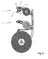
- Fig. 2 shows the roll holder 1 according to the invention with a separating device 3 and another separator 5 in a sectional view.
- the protective device 17 has two mutually facing protective edges 25, wherein the protective edges 25, the cutting edge 27 of the blade 13 in the initial position surrounded on both sides and exposing the cutting edge 27 in the cutting position.
- a spring device which presses the protective device 17 in the starting position. With the film web 15 to be separated, the protective device 17 can be pressed against the force of the spring device in the cutting position.
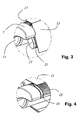
- FIGS. 3 and 4 show detailed views from FIG. 1.
- Fig. 5 shows an integrally formed protective device 17 from the side in a sectional view.
- the protective device 17 has a corrugated structure on the upper side, whereby the adhesion of the film web is reduced to an extent that allows easy operation.
- the guard 17 holds the film end in an easily graspable position; At the same time, however, the user does not have to expend any great forces in order to detach the film web 15 from the protective device 17.
Landscapes
- Life Sciences & Earth Sciences (AREA)
- Forests & Forestry (AREA)
- Engineering & Computer Science (AREA)
- Mechanical Engineering (AREA)
- Replacement Of Web Rolls (AREA)
- Folding Of Thin Sheet-Like Materials, Special Discharging Devices, And Others (AREA)
- Auxiliary Devices For And Details Of Packaging Control (AREA)
- Perforating, Stamping-Out Or Severing By Means Other Than Cutting (AREA)
- Details Of Cutting Devices (AREA)
- Nonmetal Cutting Devices (AREA)
- Processing And Handling Of Plastics And Other Materials For Molding In General (AREA)
Abstract
Description
- Die Erfindung betrifft eine Trennvorrichtung für Folienbahnen mit einer feststehenden Klinge, mittels der eine Folienbahn durchtrennbar ist, und mit einer Schutzvorrichtung, wobei die Schutzvorrichtung relativ zu der Klinge beweglich angeordnet ist und wechselweise in eine Ausgangsstellung oder eine Schneidstellung überführbar ist.
- Aus
DE 84 098 53 ist ein Rollenhalter für Folienbahnen bekannt, bei dem ein schwenkbarer Deckel mit einer Schneidklinge vorgesehen ist, mittels dem ein Abschnitt einer Folienbahn abtrennbar ist. An dem Deckel ist eine hervorstehende Schneidklinge angeordnet, an der sich der Benutzer bei unachtsamen Vorgehen verletzen kann. - Aus
GB 2255925 - Aus
EP 819460 DE 199 04 783 A1 sind Folienhalter bekannt, bei denen eine Schneidklinge mit einem Hebel verbunden ist, wobei durch eine Belastung des Hebels durch die Folienbahn die Schneidklinge verschwenkt wird, um die Folienbahn abzutrennen. Diese Vorrichtungen haben den Nachteil, dass sich der Benutzer nach dem Abtrennen der Folie, insbesondere beim Ergreifen eines neuen abzuschneidenden Folienabschnitts, verletzen kann. - Aus
US 1,231,415 ist ein Rollenhalter mit einem Abschneider bekannt, der eine verschwenkbare Abdeckung aufweist. Die verschwenkbare Abdeckung ist in einer Ausgangsposition unmittelbar vor der Schneide der Abschneidklinge angeordnet und kann mit Hilfe der abzutrennenden Folienbahn gegen die Gewichtskraft nach oben verschwenkt werden, wodurch die Abschneidklinge freigegeben wird. Diese Vorrichtung hat den Nachteil, dass die so angeordnete Abdeckung mit der Folienbahn nicht zuverlässig in die Schneidposition überführbar ist, vielmehr verklemmt sich die abzuschneidende Folienbahn im Verschwenkmechanismus der Abdeckung, ohne dass es zu einem Abtrennvorgang kommt. - Aus
EP 1 346 938 A2 ist eine Aufwickel- und Abschneidmaschine für Papierbahnen bekannt. Die Maschine weist eine Führungsvorrichtung für die Papierbahn auf, die die Papierbahn entweder zu einer Aufrollvorrichtung oder zu einer Abschneidvorrichtung leitet. - Der vorliegenden Erfindung liegt die Aufgabe zugrunde eine Trennvorrichtung anzugeben, die einerseits weitgehend sicher ist und dabei andererseits ein zuverlässiges und einfaches Abtrennen einer Folienbahn ermöglicht.
- Die Aufgabe wird durch eine Trennvorrichtung gelöst, die dadurch gekennzeichnet ist, dass zumindest der Teil der Schutzvorrichtung, der mit der zu schneidenden Folie in Berührung kommt, eine raue Oberfläche und/oder eine Wellenstruktur und/oder eine Rillenstruktur aufweist.
- Vorteilhafter Weise ist bei erfindungsgemäßen Trennvorrichtung, die insbesondere zum Abtrennen von Frischhaltefolie geeignet ist, ist zumindest der Teil der Schutzvorrichtung, der mit der zur schneidenden Folie in Berührung kommt, mit einer rauen und/oder einer Wellenstruktur aufweisenden Oberfläche versehen. In einer anderen Ausführungsform weist zumindest der Teil der Schutzvorrichtung, der mit der zu schneidenden Folie in Berührung kommt, Rillen auf. Da insbesondere Frischhaltefolie die Eigenschaft hat besonders gut anzuhaften, kann der Abtrennvorgang durch die genannte Oberflächengestaltung der Schutzvorrichtung erheblich erleichtert werden. Durch das Aufbringen einer Wellenstruktur und/oder einer rauen Oberfläche und/oder von Rillen auf die Schutzvorrichtung, ergibt sich eine geringere Kontaktfläche, wodurch der störende Klebeeffekt deutlich verringert werden kann und der Abtrennvorgang vereinfacht wird. Ein ähnlicher Effekt könnte beispielsweise durch das Aufbringen eines Gleitmittels erzielt werden. Hierbei lässt die Wirkung mit der Zeit durch Verbrauch des Gleitmittels nach und es erhebt sich die Problematik der Lebensmittelechtheit, wenn die Folienbahn zum Verpacken von Lebensmitteln verwendet werden soll. Das Wellen -bzw. das Rillenprofil hat den weiteren Vorteil, dass es ohne Mehrkosten - beispielsweise in einem Spritzgießverfahren - anbringbar ist und dass beispielsweise unvermeidbare Markierungen vom Exdrodieren im Spritzgießverfahren leicht zwischen den Rillen bzw. zwischen den Wellen leicht kaschiert werden können. In einer vorteilhaften Ausführungsform sind die Rillen bzw. die Wellen parallel zur Schneide der Klinge angeordnet.
- Erfindungsgemäß weist die Trennvorrichtung vorzugsweise eine feststehende - vorzugsweise leistenförmige Klinge auf, die vorzugsweise derart angeordnet ist, dass der Benutzer sie sieht, wodurch das Verletzungsrisiko - insbesondere im Vergleich zu beweglichen Klingen oder im Vergleich zu vollständig abgedeckten Klingen - erheblich reduziert ist.
- In einer vorteilhaften Ausgestaltungsform der erfindungsgemäßen Trennvorrichtung ist die Schutzvorrichtung relativ zu der Klinge beweglich angeordnet. In einer besonderen Ausführungsform ist die Schutzvorrichtung schwenkbar und/oder drehbar angeordnet. In einer anderen Ausführungsvariante ist die Schutzvorrichtung linear verschiebbar angeordnet.
- In einer vorteilhaften Ausgestaltungsform ist die Schutzvorrichtung derart angeordnet, dass sie in der Ausgangsstellung aus einer seitlichen Ansicht betrachtet über die Schneide hervorstehen, dadurch ist die Schneide in der Ausgangsstellung weitgehend ungefährlich, da der Benutzer die abzutrennende Folienbahn auf der Abdeckung greifen kann und somit nicht in Kontakt mit der Schneide gelangen kann.
- In einer ganz besonders vorteilhaften Ausführungsform ist die Schutzvorrichtung derart ausgeführt, dass sie mit der abzutrennenden Folienbahn in die Schneidstellung gedrückt werden kann. Hierdurch ist gewährleistet, dass der Benutzer nicht in Kontakt mit der Schneide der Klinge gerät, da er zum Herunterdrücken der Schutzvorrichtung in die Schneidstellung die abzutrennende Folienbahn in den Händen halten muss.
- Besonders vorteilhaft ist eine Ausführungsform bei der nach Ausführung des Abtrennvorgangs das beispielsweise von einer Vorratsrolle kommende Schnittende an einer der Schutzflanken der Schutzvorrichtung haften bleibt. Diese Ausführungsform hat den Vorteil, dass der Benutzer für den nächsten Abtrennvorgang die Folienbahn einfach ergreifen kann.
- Besonders vorteilhaft ist eine Ausführungsform bei der die beiden Schutzflanken der Schutzvorrichtung zusammen einstückig hergestellt sind.
- Beispielsweise können die Schutzflanken der Schutzvorrichtung die Innenflanken eines u-förmigen Schutzbauteils sein.
- In einer besonders vorteilhaften Ausgestaltungsform der erfindungsgemäßen Trennvorrichtung legt die Schutzvorrichtung in der Schneidstellung ausschließlich den zum Abtrennen notwendigen Teil der Klinge frei. Es können beispielsweise Anschlag- und/oder Fixiervorrichtungen zum vorübergehenden Fixieren der Schutzvorrichtung in der Schneidstellung vorgesehen sein. Die Variante bei der nur die zum Abtrennen notwendigen Teile der Klinge in der Schneidstellung freigelegt sind, hat den besonderen Vorteil, dass die Gefahr von schweren Verletzungen und tiefen Schnitten vermieden ist. Beispielsweise kann die erfindungsgemäße Trennvorrichtung derart ausgeführt sein, dass nur ein keiner Teil der Schneide (z.B. 0,5 mm oder 1 mm) in der Schneidstellung über die Schutzvorrichtung herausragt. Es sind daher keine Verletzungsschnitte möglich, die tiefer gehen, als das Maß in dem die Klinge über die Schutzvorrichtung in der Schneidstellung überhaupt herausragen kann.
- In einer besonderen Ausgestaltungsform ist eine Federeinrichtung vorgesehen, die die Schutzvorrichtung in die Ausgangstellung drückt. In dieser Ausführungsform ist vorgesehen, dass der Benutzer - idealerweise mit der Folienbahn selbst - die Schutzvorrichtung gegen die Kraft der Federeinrichtung aus der Ausgangstellung in die Schneidstellung drückt, um einen Abtrennvorgang auszuführen. Nach erfolgtem Abtrennvorgang drückt die Federeinrichtung die Schutzvorrichtung automatisch aus der Schneidstellung in die Ausgangsstellung zurück.
- In einer mit besonders wenigen Bauteilen herzustellenden Ausführungsform der erfindungsgemäßen Trennvorrichtung ist die Klinge in einem U-Profil gehaltert. Diese Ausführungsform erlaubt es, dünne Klingen zu verwenden, insbesondere dann, wenn es sich um ein u-förmiges Metallprofil handelt, das der Klinge seine Steifigkeit verleiht. Hierdurch wird die Durchbiegung der Klinge, insbesondere im mittleren Bereich, erheblich reduziert.
- In einer Ausführungsform weist die Klinge eine gerade Schneide auf. In einer anderen Ausführungsform weist die Klinge eine gezackte und/oder eine gewellte Schneide auf. Die Ausführungsart der Schneide kann auf die Eigenschaften der zu schneidenden Folienbahn abgestimmt werden.
- Erfindungsgemäß lässt sich die Trennvorrichtung besonders gut mit Rollenhaltern, beispielsweise mit Wandrollenhaltern, einsetzen. Besonders vorteilhaft sind Rollenhalter, die mit einer erfindungsgemäßen Trennvorrichtung ausgerüstet sind.
- Ein solcher Rollenhalter weist vorzugsweise eine Haltevorrichtung zur Aufnahme zumindest Vorratsrolle auf. In einer vorteilhaften Ausführungsform des Rollenhalters sind zumindest zwei hervorstehende Arme zum Tragen einer Vorratsrolle vorgesehen. In einer besonders kompakten und leicht zu handhabenden Ausführungsform eines Rollenhalters ist die Trennvorrichtung an den hervorstehenden Armen angeordnet. Ein Rollenhalter kann mehrere Trennvorrichtungen und/oder mehrere Aufnahmen für mehrere Vorratsrollen aufweisen.
- In der Zeichnung ist der Erfindungsgegenstand schematisch dargestellt und wird anhand der Figuren nachfolgend beschrieben, wobei gleich wirkende Elemente mit denselben Bezugszeichen versehen sind. Dabei zeigt:
- Fig. 1
- Einen erfindungsgemäßen Rollenhalter mit einer Trennvorrichtung in einer Perspektivansicht,
- Fig. 2
- einen erfindungsgemäßen Rollenhalter mit einer Trennvorrichtung in einer Schnittdarstellung,
- Fig. 3
- eine Detaildarstellung einer erfindungsgemäßen Trennvorrichtung,
- Fig. 4
- eine weitere Detaildarstellung einer erfindungsgemäßen Trennvorrichtung, und
- Fig. 5
- eine einstückig ausgebildete Schutzvorrichtung von der Seite.
- Fig. 1 zeigt einen erfindungsgemäßen Rollenhalter 1 mit einer Trennvorrichtung 3 und einer weiteren Trennvorrichtung 5 in einer Perspektivansicht. Die Trennvorrichtung 3 und die zweite Trennvorrichtung 5 sind gleich aufgebaut. Der Rollenhalter 1 weist zwei hervorstehende Arme 7, 9 mit einer Haltevorrichtung zur Aufnahme einer auf Vorratsrolle 11 auf. An den hervorstehende Arme 7, 9 ist auch die Trennvorrichtung 3 angeordnet. Die Trennvorrichtung 3 weist eine feststehende Klinge 13, mittels der die auf Vorratsrolle 11 aufgewickelte Folienbahn 15 durchtrennbar ist. Ferner ist eine Schutzvorrichtung 17 vorgesehen, die relativ zu der Klinge 13 beweglich - nämlich schwenkbar - ist und wechselweise in eine Ausgangsstellung oder eine Schneidstellung überführbar ist. Die Schutzvorrichtung 17 der Trennvorrichtung 3 ist in der Schneidstellung dargestellt. Die weitere Schutzvorrichtung 19 der weiteren Trennvorrichtung 5 ist in der Ausgangsstellung gezeigt.
- Jeweils zumindest der Teil der Schutzvorrichtung 17 bzw. der weiteren Schutzvorrichtung 19, der mit der zu schneidenden Folie in Berührung kommt, weist eine Rillenstruktur 21, 23 auf. Die Rillen sind parallel zur Schneide der Klinge 13 angeordnet
- Fig. 2 zeigt den erfindungsgemäßen Rollenhalter 1 mit einer Trennvorrichtung 3 und einer weiteren Trennvorrichtung 5 in einer Schnittdarstellung.
- Die Schutzvorrichtung 17 weist zwei einander zugewandte Schutzflanken 25 aufweist, wobei die Schutzflanken 25 die Schneide 27 der Klinge 13 in der Ausgangsstellung beidseitig umgeben und in der Schneidstellung die Schneide 27 freilegen.
- Es ist eine nicht dargestellte Federeinrichtung vorgesehen, die die Schutzvorrichtung 17 in die Ausgangsstellung drückt. Mit der abzutrennenden Folienbahn 15 kann die Schutzvorrichtung 17 gegen die Kraft der Federeinrichtung in die Schneidstellung gedrückt werden.
- Die Figuren 3 und 4 zeigen Detaildarstellungen aus Fig. 1.
- Fig. 5 zeigt eine einstückig ausgebildete Schutzvorrichtung 17 von der Seite in einer Schnittdarstellung. Die Schutzvorrichtung 17 weist eine Wellelstruktur auf der Oberseite auf, wodurch das Anhaften der Folienbahn auf ein Maß vermindert wird, das eine leichte Bedienbarkeit ermöglicht. Die Schutzvorrichtung 17 hält das Folienende in einer leicht greifbaren Position fest; gleichzeitig muss der Benutzer jedoch keine großen Kräfte aufwenden, um die Folienbahn 15 von der Schutzvorrichtung 17 zu lösen.
- Die Erfindung wurde in Bezug auf eine besondere Ausführungsform beschrieben. Es ist jedoch selbstverständlich, dass Änderungen und Abwandlungen durchgeführt werden können, ohne dabei den Schutzbereich der nachstehenden Ansprüche zu verlassen.
-
- 1
- Rollenhalter
- 3
- Trennvorrichtung
- 5
- weitere Trennvorrichtung
- 7
- Arm
- 9
- Arm
- 11
- Vorratsrolle
- 13
- Klinge
- 15
- Folienbahn
- 17
- Schutzvorrichtung
- 19
- weitere Schutzvorrichtung
- 21
- Rillenstruktur
- 23
- Rillenstruktur
- 25
- Schutzflanken
- 27
- Schneide
Claims (10)
- Trennvorrichtung für Folienbahnen mit einer feststehenden Klinge, mittels der eine Folienbahn durchtrennbar ist, und mit einer Schutzvorrichtung, wobei die Schutzvorrichtung relativ zu der Klinge beweglich angeordnet ist und wechselweise in eine Ausgangsstellung oder eine Schneidstellung überführbar ist, dadurch gekennzeichnet, dass zumindest der Teil der Schutzvorrichtung, der mit der zu schneidenden Folie in Berührung kommt, eine raue Oberfläche und/oder eine Wellenstruktur und/oder eine Rillenstruktur aufweist.
- Trennvorrichtung nach Anspruch 1, dadurch gekennzeichnet, dass die Schutzvorrichtung zwei einander zugewandte Schutzflanken aufweist, wobei die Schutzflanken die Schneide der Klinge in der Ausgangsstellung beidseitig umgeben und in der Schneidstellung die Schneide freilegen.
- Trennvorrichtung nach einem der Ansprüche 1 oder 2, dadurch gekennzeichnet, dass zumindest der Teil der Schutzvorrichtung, der mit der zu schneidenden Folie in Berührung kommt, Rillen aufweist, die parallel zur Schneide angeordnet sind.
- Trennvorrichtung nach einem der Ansprüche 1 bis 3, dadurch gekennzeichnet, dass die Schutzvorrichtung schwenkbar und/oder drehbar und/oder linear verschiebbar angeordnet ist.
- Trennvorrichtung nach einem der Ansprüche 1 bis 4, dadurch gekennzeichnet, dass die beiden Schutzflanken die Innenflanken eines u-förmigen Schutzbauteils sind.
- Trennvorrichtung nach einem der Ansprüche 1 bis 5, dadurch gekennzeichnet, dass die Schutzvorrichtung in der Schneidstellung ausschließlich den zum Abtrennen notwendigen Teil der Klinge freilegt.
- Trennvorrichtung nach einem der Ansprüche 1 bis 6, dadurch gekennzeichnet, dass eine Anschlag- und/oder Fixiervorrichtung zum vorübergehenden Fixieren der Schutzvorrichtung in der Schneidstellung vorgesehen ist.
- Trennvorrichtung nach einem der Ansprüche 1 bis 7, dadurch gekennzeichnet, dass eine Federeinrichtung vorgesehen ist, die die Schutzvorrichtung in die Ausgangsstellung drückt.
- Rollenhalter mit zumindest einer Trennvorrichtung nach einem der Ansprüche 1 bis 8.
- Rollenhalter nach Anspruch 9, dadurch gekennzeichnet, dass der Rollenhalter zumindest zwei hervorstehende Arme zum Tragen einer Vorratsrolle aufweist und dass die Trennvorrichtung an den hervorstehenden Armen angeordnet ist.
Applications Claiming Priority (1)
| Application Number | Priority Date | Filing Date | Title |
|---|---|---|---|
| DE102005057390A DE102005057390A1 (de) | 2005-11-30 | 2005-11-30 | Trennvorrichtung für Folienbahnen |
Publications (3)
| Publication Number | Publication Date |
|---|---|
| EP1792863A2 true EP1792863A2 (de) | 2007-06-06 |
| EP1792863A3 EP1792863A3 (de) | 2007-08-01 |
| EP1792863B1 EP1792863B1 (de) | 2009-12-16 |
Family
ID=37806065
Family Applications (1)
| Application Number | Title | Priority Date | Filing Date |
|---|---|---|---|
| EP06024388A Not-in-force EP1792863B1 (de) | 2005-11-30 | 2006-11-24 | Trennvorrichtung für Folienbahnen |
Country Status (4)
| Country | Link |
|---|---|
| EP (1) | EP1792863B1 (de) |
| AT (1) | ATE452096T1 (de) |
| DE (2) | DE102005057390A1 (de) |
| ES (1) | ES2337171T3 (de) |
Family Cites Families (3)
| Publication number | Priority date | Publication date | Assignee | Title |
|---|---|---|---|---|
| US3311278A (en) * | 1965-10-12 | 1967-03-28 | Auzvill Jackson Jr | Dispenser and cutter and the like |
| DE29612436U1 (de) * | 1996-07-17 | 1996-09-19 | Heinrich J. Kesseböhmer Draht- und Metallwarenfabrik, 49152 Bad Essen | Trennvorrichtung für Folienbahnen |
| US6725753B2 (en) * | 2002-07-03 | 2004-04-27 | Clinton C. Bell | Dispenser for rolled material |
-
2005
- 2005-11-30 DE DE102005057390A patent/DE102005057390A1/de not_active Withdrawn
-
2006
- 2006-11-24 DE DE502006005653T patent/DE502006005653D1/de active Active
- 2006-11-24 ES ES06024388T patent/ES2337171T3/es active Active
- 2006-11-24 AT AT06024388T patent/ATE452096T1/de active
- 2006-11-24 EP EP06024388A patent/EP1792863B1/de not_active Not-in-force
Also Published As
| Publication number | Publication date |
|---|---|
| EP1792863A3 (de) | 2007-08-01 |
| ES2337171T3 (es) | 2010-04-21 |
| DE502006005653D1 (de) | 2010-01-28 |
| ATE452096T1 (de) | 2010-01-15 |
| DE102005057390A1 (de) | 2007-05-31 |
| EP1792863B1 (de) | 2009-12-16 |
Similar Documents
| Publication | Publication Date | Title |
|---|---|---|
| DE2003354C3 (de) | Vorrichtung zum Abziehen flexiblen blattförmigen Materials | |
| DE2342395A1 (de) | Rasierapparat | |
| DE102017110516B4 (de) | Einrichtung zum Abtrennen von Papierabschnitten von auf einer Papierrolle aufgewickelten Papierbahn sowie Messer zum Abtrennen der Papierabschnitte | |
| DE3025345A1 (de) | Abrollvorrichtung zum auftragen eines bandes auf eine arbeitsflaeche. | |
| DE202015100507U1 (de) | Abisolierzange | |
| DE202015105416U1 (de) | Rotierende Schneid- und/oder Perforiervorrichtung für flächiges Endlosmaterial | |
| DE2804555C3 (de) | Abgabevorrichtung für beliebig lange abgetrennte Stücke von einem Vorrat eines Flachmaterials kontinuierlicher Länge | |
| DE60010762T2 (de) | Versiegelte verpackung für wundheftpflaster | |
| DE102017110518B4 (de) | Vorrichtung zur Ausgabe von Papierabschnitten vorgegebener Länge | |
| EP2837590B1 (de) | Bogen-Brems-Vorrichtung, und Anlage zum Bereitstellen von Bögen umfassend eine solche Vorrichtung | |
| DE69004995T2 (de) | Schnittkantenschutz. | |
| DE202013003963U1 (de) | Abgabegerät | |
| EP1792863B1 (de) | Trennvorrichtung für Folienbahnen | |
| DE1436633C3 (de) | Vorrichtung zum Herstellen von be druckten Etiketten | |
| EP3954241A1 (de) | Hygieneüberzieher | |
| DE102014002065A1 (de) | Schneidevorrichtung zum Durchtrennen der Abdeckschicht eines Klebebandes | |
| DE69408226T2 (de) | Bandeschneidegerät | |
| DE19711611C2 (de) | Halteplatte eines Staubsauger-Filterbeutels | |
| EP2060372A1 (de) | Bürogerät zur Bearbeitung von Blattgut | |
| DE19631964A1 (de) | Ablängvorrichtung | |
| EP0819640B1 (de) | Trennvorrichtung für Folienbahnen | |
| EP0785892B1 (de) | Vorrichtung zur ausgabe von etiketten | |
| DE102010007002A1 (de) | Bandschneider | |
| EP1493540B1 (de) | Papierschneidgerät | |
| WO2023025691A1 (de) | Vorrichtung zum erstellen eines kinesiobandes |
Legal Events
| Date | Code | Title | Description |
|---|---|---|---|
| PUAI | Public reference made under article 153(3) epc to a published international application that has entered the european phase |
Free format text: ORIGINAL CODE: 0009012 |
|
| AK | Designated contracting states |
Kind code of ref document: A2 Designated state(s): AT BE BG CH CY CZ DE DK EE ES FI FR GB GR HU IE IS IT LI LT LU LV MC NL PL PT RO SE SI SK TR |
|
| AX | Request for extension of the european patent |
Extension state: AL BA HR MK YU |
|
| PUAL | Search report despatched |
Free format text: ORIGINAL CODE: 0009013 |
|
| AK | Designated contracting states |
Kind code of ref document: A3 Designated state(s): AT BE BG CH CY CZ DE DK EE ES FI FR GB GR HU IE IS IT LI LT LU LV MC NL PL PT RO SE SI SK TR |
|
| AX | Request for extension of the european patent |
Extension state: AL BA HR MK YU |
|
| RIC1 | Information provided on ipc code assigned before grant |
Ipc: B26D 7/22 20060101ALI20070622BHEP Ipc: B65H 35/00 20060101AFI20070309BHEP |
|
| 17P | Request for examination filed |
Effective date: 20070814 |
|
| 17Q | First examination report despatched |
Effective date: 20071005 |
|
| AKX | Designation fees paid |
Designated state(s): AT BE BG CH CY CZ DE DK EE ES FI FR GB GR HU IE IS IT LI LT LU LV MC NL PL PT RO SE SI SK TR |
|
| GRAP | Despatch of communication of intention to grant a patent |
Free format text: ORIGINAL CODE: EPIDOSNIGR1 |
|
| GRAS | Grant fee paid |
Free format text: ORIGINAL CODE: EPIDOSNIGR3 |
|
| GRAA | (expected) grant |
Free format text: ORIGINAL CODE: 0009210 |
|
| AK | Designated contracting states |
Kind code of ref document: B1 Designated state(s): AT BE BG CH CY CZ DE DK EE ES FI FR GB GR HU IE IS IT LI LT LU LV MC NL PL PT RO SE SI SK TR |
|
| REG | Reference to a national code |
Ref country code: GB Ref legal event code: FG4D Free format text: NOT ENGLISH |
|
| REG | Reference to a national code |
Ref country code: CH Ref legal event code: NV Representative=s name: ISLER & PEDRAZZINI AG Ref country code: CH Ref legal event code: EP |
|
| REG | Reference to a national code |
Ref country code: IE Ref legal event code: FG4D |
|
| REF | Corresponds to: |
Ref document number: 502006005653 Country of ref document: DE Date of ref document: 20100128 Kind code of ref document: P |
|
| REG | Reference to a national code |
Ref country code: NL Ref legal event code: T3 |
|
| REG | Reference to a national code |
Ref country code: ES Ref legal event code: FG2A Ref document number: 2337171 Country of ref document: ES Kind code of ref document: T3 |
|
| PG25 | Lapsed in a contracting state [announced via postgrant information from national office to epo] |
Ref country code: FI Free format text: LAPSE BECAUSE OF FAILURE TO SUBMIT A TRANSLATION OF THE DESCRIPTION OR TO PAY THE FEE WITHIN THE PRESCRIBED TIME-LIMIT Effective date: 20091216 Ref country code: SE Free format text: LAPSE BECAUSE OF FAILURE TO SUBMIT A TRANSLATION OF THE DESCRIPTION OR TO PAY THE FEE WITHIN THE PRESCRIBED TIME-LIMIT Effective date: 20091216 Ref country code: LT Free format text: LAPSE BECAUSE OF FAILURE TO SUBMIT A TRANSLATION OF THE DESCRIPTION OR TO PAY THE FEE WITHIN THE PRESCRIBED TIME-LIMIT Effective date: 20091216 |
|
| LTIE | Lt: invalidation of european patent or patent extension |
Effective date: 20091216 |
|
| PG25 | Lapsed in a contracting state [announced via postgrant information from national office to epo] |
Ref country code: PL Free format text: LAPSE BECAUSE OF FAILURE TO SUBMIT A TRANSLATION OF THE DESCRIPTION OR TO PAY THE FEE WITHIN THE PRESCRIBED TIME-LIMIT Effective date: 20091216 Ref country code: SI Free format text: LAPSE BECAUSE OF FAILURE TO SUBMIT A TRANSLATION OF THE DESCRIPTION OR TO PAY THE FEE WITHIN THE PRESCRIBED TIME-LIMIT Effective date: 20091216 Ref country code: LV Free format text: LAPSE BECAUSE OF FAILURE TO SUBMIT A TRANSLATION OF THE DESCRIPTION OR TO PAY THE FEE WITHIN THE PRESCRIBED TIME-LIMIT Effective date: 20091216 |
|
| REG | Reference to a national code |
Ref country code: IE Ref legal event code: FD4D |
|
| PG25 | Lapsed in a contracting state [announced via postgrant information from national office to epo] |
Ref country code: PT Free format text: LAPSE BECAUSE OF FAILURE TO SUBMIT A TRANSLATION OF THE DESCRIPTION OR TO PAY THE FEE WITHIN THE PRESCRIBED TIME-LIMIT Effective date: 20100416 Ref country code: RO Free format text: LAPSE BECAUSE OF FAILURE TO SUBMIT A TRANSLATION OF THE DESCRIPTION OR TO PAY THE FEE WITHIN THE PRESCRIBED TIME-LIMIT Effective date: 20091216 Ref country code: IS Free format text: LAPSE BECAUSE OF FAILURE TO SUBMIT A TRANSLATION OF THE DESCRIPTION OR TO PAY THE FEE WITHIN THE PRESCRIBED TIME-LIMIT Effective date: 20100416 Ref country code: IE Free format text: LAPSE BECAUSE OF FAILURE TO SUBMIT A TRANSLATION OF THE DESCRIPTION OR TO PAY THE FEE WITHIN THE PRESCRIBED TIME-LIMIT Effective date: 20091216 Ref country code: BG Free format text: LAPSE BECAUSE OF FAILURE TO SUBMIT A TRANSLATION OF THE DESCRIPTION OR TO PAY THE FEE WITHIN THE PRESCRIBED TIME-LIMIT Effective date: 20100316 Ref country code: EE Free format text: LAPSE BECAUSE OF FAILURE TO SUBMIT A TRANSLATION OF THE DESCRIPTION OR TO PAY THE FEE WITHIN THE PRESCRIBED TIME-LIMIT Effective date: 20091216 |
|
| PG25 | Lapsed in a contracting state [announced via postgrant information from national office to epo] |
Ref country code: CZ Free format text: LAPSE BECAUSE OF FAILURE TO SUBMIT A TRANSLATION OF THE DESCRIPTION OR TO PAY THE FEE WITHIN THE PRESCRIBED TIME-LIMIT Effective date: 20091216 Ref country code: SK Free format text: LAPSE BECAUSE OF FAILURE TO SUBMIT A TRANSLATION OF THE DESCRIPTION OR TO PAY THE FEE WITHIN THE PRESCRIBED TIME-LIMIT Effective date: 20091216 |
|
| PLBE | No opposition filed within time limit |
Free format text: ORIGINAL CODE: 0009261 |
|
| STAA | Information on the status of an ep patent application or granted ep patent |
Free format text: STATUS: NO OPPOSITION FILED WITHIN TIME LIMIT |
|
| PG25 | Lapsed in a contracting state [announced via postgrant information from national office to epo] |
Ref country code: CY Free format text: LAPSE BECAUSE OF FAILURE TO SUBMIT A TRANSLATION OF THE DESCRIPTION OR TO PAY THE FEE WITHIN THE PRESCRIBED TIME-LIMIT Effective date: 20091216 Ref country code: GR Free format text: LAPSE BECAUSE OF FAILURE TO SUBMIT A TRANSLATION OF THE DESCRIPTION OR TO PAY THE FEE WITHIN THE PRESCRIBED TIME-LIMIT Effective date: 20100317 |
|
| 26N | No opposition filed |
Effective date: 20100917 |
|
| PG25 | Lapsed in a contracting state [announced via postgrant information from national office to epo] |
Ref country code: DK Free format text: LAPSE BECAUSE OF FAILURE TO SUBMIT A TRANSLATION OF THE DESCRIPTION OR TO PAY THE FEE WITHIN THE PRESCRIBED TIME-LIMIT Effective date: 20091216 |
|
| PGFP | Annual fee paid to national office [announced via postgrant information from national office to epo] |
Ref country code: FR Payment date: 20101109 Year of fee payment: 5 Ref country code: NL Payment date: 20101025 Year of fee payment: 5 |
|
| PGFP | Annual fee paid to national office [announced via postgrant information from national office to epo] |
Ref country code: CH Payment date: 20101025 Year of fee payment: 5 Ref country code: DE Payment date: 20101006 Year of fee payment: 5 |
|
| PGFP | Annual fee paid to national office [announced via postgrant information from national office to epo] |
Ref country code: IT Payment date: 20101027 Year of fee payment: 5 Ref country code: BE Payment date: 20101116 Year of fee payment: 5 |
|
| PG25 | Lapsed in a contracting state [announced via postgrant information from national office to epo] |
Ref country code: MC Free format text: LAPSE BECAUSE OF NON-PAYMENT OF DUE FEES Effective date: 20101130 |
|
| PGFP | Annual fee paid to national office [announced via postgrant information from national office to epo] |
Ref country code: ES Payment date: 20101123 Year of fee payment: 5 |
|
| GBPC | Gb: european patent ceased through non-payment of renewal fee |
Effective date: 20101124 |
|
| PG25 | Lapsed in a contracting state [announced via postgrant information from national office to epo] |
Ref country code: GB Free format text: LAPSE BECAUSE OF NON-PAYMENT OF DUE FEES Effective date: 20101124 |
|
| BERE | Be: lapsed |
Owner name: LEIFHEIT A.G. Effective date: 20111130 |
|
| REG | Reference to a national code |
Ref country code: NL Ref legal event code: V1 Effective date: 20120601 |
|
| REG | Reference to a national code |
Ref country code: CH Ref legal event code: PL |
|
| PG25 | Lapsed in a contracting state [announced via postgrant information from national office to epo] |
Ref country code: NL Free format text: LAPSE BECAUSE OF NON-PAYMENT OF DUE FEES Effective date: 20120601 Ref country code: CH Free format text: LAPSE BECAUSE OF NON-PAYMENT OF DUE FEES Effective date: 20111130 Ref country code: LI Free format text: LAPSE BECAUSE OF NON-PAYMENT OF DUE FEES Effective date: 20111130 |
|
| REG | Reference to a national code |
Ref country code: FR Ref legal event code: ST Effective date: 20120731 |
|
| PG25 | Lapsed in a contracting state [announced via postgrant information from national office to epo] |
Ref country code: BE Free format text: LAPSE BECAUSE OF NON-PAYMENT OF DUE FEES Effective date: 20111130 Ref country code: IT Free format text: LAPSE BECAUSE OF NON-PAYMENT OF DUE FEES Effective date: 20111124 |
|
| REG | Reference to a national code |
Ref country code: DE Ref legal event code: R119 Ref document number: 502006005653 Country of ref document: DE Effective date: 20120601 |
|
| PG25 | Lapsed in a contracting state [announced via postgrant information from national office to epo] |
Ref country code: LU Free format text: LAPSE BECAUSE OF NON-PAYMENT OF DUE FEES Effective date: 20101124 Ref country code: HU Free format text: LAPSE BECAUSE OF FAILURE TO SUBMIT A TRANSLATION OF THE DESCRIPTION OR TO PAY THE FEE WITHIN THE PRESCRIBED TIME-LIMIT Effective date: 20100617 |
|
| PG25 | Lapsed in a contracting state [announced via postgrant information from national office to epo] |
Ref country code: TR Free format text: LAPSE BECAUSE OF FAILURE TO SUBMIT A TRANSLATION OF THE DESCRIPTION OR TO PAY THE FEE WITHIN THE PRESCRIBED TIME-LIMIT Effective date: 20091216 |
|
| PG25 | Lapsed in a contracting state [announced via postgrant information from national office to epo] |
Ref country code: FR Free format text: LAPSE BECAUSE OF NON-PAYMENT OF DUE FEES Effective date: 20111130 |
|
| REG | Reference to a national code |
Ref country code: AT Ref legal event code: MM01 Ref document number: 452096 Country of ref document: AT Kind code of ref document: T Effective date: 20111124 |
|
| PG25 | Lapsed in a contracting state [announced via postgrant information from national office to epo] |
Ref country code: AT Free format text: LAPSE BECAUSE OF NON-PAYMENT OF DUE FEES Effective date: 20111124 |
|
| PG25 | Lapsed in a contracting state [announced via postgrant information from national office to epo] |
Ref country code: DE Free format text: LAPSE BECAUSE OF NON-PAYMENT OF DUE FEES Effective date: 20120601 |
|
| REG | Reference to a national code |
Ref country code: ES Ref legal event code: FD2A Effective date: 20130715 |
|
| PG25 | Lapsed in a contracting state [announced via postgrant information from national office to epo] |
Ref country code: ES Free format text: LAPSE BECAUSE OF NON-PAYMENT OF DUE FEES Effective date: 20111125 |