EP1790767A2 - Wäscheständer - Google Patents
Wäscheständer Download PDFInfo
- Publication number
- EP1790767A2 EP1790767A2 EP06124541A EP06124541A EP1790767A2 EP 1790767 A2 EP1790767 A2 EP 1790767A2 EP 06124541 A EP06124541 A EP 06124541A EP 06124541 A EP06124541 A EP 06124541A EP 1790767 A2 EP1790767 A2 EP 1790767A2
- Authority
- EP
- European Patent Office
- Prior art keywords
- stiffening
- clothes drying
- crossmember
- drying hanger
- disengagement
- Prior art date
- Legal status (The legal status is an assumption and is not a legal conclusion. Google has not performed a legal analysis and makes no representation as to the accuracy of the status listed.)
- Granted
Links
- 238000001035 drying Methods 0.000 title claims abstract description 34
- 230000014759 maintenance of location Effects 0.000 claims description 12
- 230000002441 reversible effect Effects 0.000 claims description 4
- 230000008878 coupling Effects 0.000 claims description 2
- 238000010168 coupling process Methods 0.000 claims description 2
- 238000005859 coupling reaction Methods 0.000 claims description 2
- 239000000463 material Substances 0.000 description 4
- 238000003780 insertion Methods 0.000 description 2
- 230000037431 insertion Effects 0.000 description 2
- 230000000670 limiting effect Effects 0.000 description 2
- 238000005516 engineering process Methods 0.000 description 1
- 238000000034 method Methods 0.000 description 1
Images

Classifications
-
- D—TEXTILES; PAPER
- D06—TREATMENT OF TEXTILES OR THE LIKE; LAUNDERING; FLEXIBLE MATERIALS NOT OTHERWISE PROVIDED FOR
- D06F—LAUNDERING, DRYING, IRONING, PRESSING OR FOLDING TEXTILE ARTICLES
- D06F57/00—Supporting means, other than simple clothes-lines, for linen or garments to be dried or aired
- D06F57/08—Folding stands
Definitions
- the present invention relates to a clothes drying hanger of the type with an extensible clothes hanging rack for hanging clothes.
- Clothes drying hangers are known which are provided with a rack for hanging clothes which can be extended in order to vary the load capacity and adapt it to the space in which the drying hanger is arranged.
- a clothes drying hanger of the type which comprises a quadrangular frame structure constituted by two longitudinal members and two opposite crossmembers, between which rod-like components are arranged which form, together with the quadrangular frame structure, a single rack for hanging clothes which can be extended along the longitudinal direction of said rod-like components; supporting legs which have a scissor-like articulation are coupled to said longitudinal members.
- each rod-like component is constituted by two elements which are mutually coupled slidingly and are fixed respectively to a corresponding crossmember.
- clothes drying hanger further includes a pair of stiffening crossmembers, which connect the ends of the legs; when the clothes drying hanger is open in the active configuration, each rod-like component lies proximate to the stiffening crossmembers.
- This clothes drying hanger solves in an optimum manner the problem of load variability but is not free from drawbacks.
- the aim of the present invention is to provide a clothes drying hanger which is capable of changing its dimensions and therefore its clothes loading capacity in order to optimize the space available but without renouncing the presence of stiffening crossmembers when needed.
- an object of the present invention is to provide a clothes drying hanger which is particularly easy to move when changing configuration.
- Another object of the present invention is to provide a clothes drying hanger which can be manufactured with known systems and technologies.
- a clothes drying hanger of the type which comprises a quadrangular frame structure constituted by two longitudinal members and two opposite crossmembers, between which rod-like components are arranged which form, together with said quadrangular frame structure, a single rack for hanging clothes which can be extended in the longitudinal direction of said rod-like components, supporting legs being rigidly coupled to said longitudinal members, a mutually opposite and parallel pair of rod-like portions protruding from the ends of each of said crossmembers and forming, together with said crossmembers, a U-shaped configuration, said rod-like portions being slidingly coupled to said longitudinal members, each rod-like component being constituted by two elements which are mutually coupled slidingly and are fixed respectively to a corresponding said crossmember, said clothes drying hanger further comprising two stiffening crossmembers, each of which connects two corresponding portions of said supporting legs associated with separate longitudinal members, each rod-like component, when the clothes hanger is open in the active configuration, being proximate to said
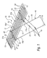
- a clothes drying hanger according to the invention is generally designated by the reference numeral 10.
- the clothes hanger 10 comprises a quadrangular frame structure 11, which is constituted by two tubular longitudinal members 12 and two mutually opposite crossmembers 13, between which rod-like components 14, which are likewise tubular, are arranged parallel to each other and to the longitudinal members 12.
- the rod-like components 14 form, together with the quadrangular frame structure 11, a single rack 15 for hanging clothes; the rack 15 can be extended in the longitudinal direction of the rod-like components 14, as described in greater detail hereinafter ( Figure 1 shows in broken lines the direction of elongation of the rack 15).
- Supporting legs 16 for example of the scissor-like type, are pivoted to the tubular longitudinal members 12 substantially at the ends.
- the supporting legs 16 of the scissor-like type are constituted by two separate U-shaped legs, respectively a first U-shaped leg 17 and a second U-shaped leg 18, each of which is pivoted by the ends of the U-shape to corresponding ends of the two tubular longitudinal members 12.
- the horizontal portions 19 of the U-shaped legs 17 and 18 act as a supporting base.
- the first U-shaped leg 17 has, above the point 20 for pivoting with the second U-shaped leg 18, on both arms of the U-shape, respective joints 21 in order to allow 180° folding of the first U-shaped leg 17 in order to allow the collapse of the legs so as to assume a flattened configuration on the quadrangular frame structure 11.
- the rod-like portions 22 are slidingly coupled by insertion in the longitudinal members 12, which, as mentioned, are tubular in this embodiment.
- Each rod-like component 14 is constituted by two elements, respectively a first element 23 and a second element 24, which are mutually coupled slidingly by mutual insertion; in particular, the first element 23, which has a circular cross-section, is inserted in the second element 24, which is tubular.
- Each element 23 and 24 is fixed to a corresponding crossmember 13.
- the pivoting of the legs 16 to the longitudinal members 12 occurs by means of a hinge block 27, which is fixed both to the longitudinal members and to the legs.
- the hinge block 27 is constituted for example by a bush made of plastic material, which is keyed at the end to the longitudinal members 12.
- the clothes drying hanger 10 further comprises two stiffening crossmembers 31.
- Each stiffening crossmember 31 connects the ends of each U-shaped leg 17 and 18 substantially proximate to the hinge block 27.
- Slots 32 are further formed longitudinally on the stiffening crossmembers 31 in order to accommodate the rod-like components 14 once the clothes hanger 10 has been arranged in the closed inactive configuration, with the legs 16 flattened onto the frame structure 11.
- the stiffening crossmembers 31 connect two corresponding supporting leg portions which are associated with separate longitudinal members 12; in particular, one crossmember 31, termed first crossmember 31 a, is connected between the portions of supporting leg 18a which form the ends of the second U-shaped leg 18, while the other crossmember 31, termed second crossmember 31b, is connected between the portions of supporting leg 17a which form the ends of the first U-shaped leg 17.
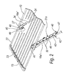
- the clothes drying hanger 10 is provided with quick engagement/disengagement means 40 for one of the stiffening crossmembers 31 on the supporting legs 16, so as to provide a rack 15 which is free from transverse obstacles, to be used if it is necessary to hang large items.
- the quick engagement/disengagement means 40 are associated with the first crossmember 31a.
- quick engagement/disengagement means 40 can be provided also on both of the stiffening crossmembers 31 depending on design requirements.
- the first stiffening crossmember 31a is connected to a respective leg portion 18a' by means of a hinge 41 which is formed at one end, while the means 40 for quick engagement/disengagement (described hereinafter) on the opposite leg portion 18a" are provided at the opposite end.
- the first stiffening crossmember 31 a is arranged, when the quick engagement/disengagement means 40 are in the disengagement configuration, in a configuration in which the rack 15 substantially has no obstacles.
- stiffening crossmember 31a can be arranged, when the quick engagement/disengagement means 40 are in the disengagement configuration, along the leg portion 18a' to which it is pivoted, as shown in Figure 2.
- the axis of the hinge 41 is substantially perpendicular to the plane on which the longitudinal axes of the leg portions 18a' and 18a" are arranged, connected by the stiffening crossmember 31a, which in practice is perpendicular to the plane of arrangement on which the U-shaped configuration of the first leg 17 is arranged.
- the first stiffening crossmember 31 a is provided with means 42 for reversible locking to the leg portion 16 to which it is pivoted, said means being active when the quick engagement/disengagement means 41 are in the disengagement configuration and therefore the stiffening crossmember 31 is arranged along the corresponding second leg portion 18a'.
- the reversible locking means 42 comprise two parallel tabs 43 with an enlarged head, which are elastically deformable and protrude from the face 46 of the stiffening crossmember 31a which is directed, when the first crossmember 31a is in a configuration in which it substantially does not form an obstacle on the rack 15, toward the leg portion 18a' to which it is pivoted.
- the tabs 43 lie on opposite sides of the leg portion 18a', and lock it; the enlarged heads form an extraction-preventing undercut for the leg portion 18a'.
- the quick engagement/disengagement means 40 are formed at one end of the first stiffening crossmember 31a, the one which lies opposite the hinge 41.
- the quick engagement/disengagement means can be associated with both ends of the first crossmember 31a, making it completely disengageable from the supporting structure of the clothes drying hanger.
- the quick engagement/disengagement means 40 comprise a coupling which is formed by a retention body 47, which is elastically flexible and is suitable to mate with a corresponding locking seat 48.
- the elastically flexible retention body 47 is arranged at the end of the first stiffening crossmember 31a, while the corresponding locking seat 48 is formed on the corresponding leg portion 18a".
- leg portions 18a' and 18a" are fitted on corresponding identical bushes 34 made of plastic material; the hinge blocks 27 of the longitudinal members 12 are pivoted on said bushes.
- the cradle 49 is provided with two mutually opposite walls 50, in one of which there is a through hole which forms the locking seat 48 for the retention body 47.
- the end portion 47a of the retention body 47 when it is in the engagement configuration, protrudes from the through hole which forms the locking seat 48 and can be available as a release button to a user.
- the retention body 47 is constituted by a ring 51 made of elastically deformable plastic material, which is arranged within a compartment 52 formed inside the first stiffening crossmember 31a.
- the ring is locked between the two mutually opposite walls 50 of the cradle 49; a stud protrudes from a circumferential external position of the ring 51 and forms the end portion 47a, which can be inserted in the locking seat 47.
- An additional cradle 53 for the end of the first stiffening crossmember 31a associated with the hinge 41 is provided on the bush 34 related to the pivoting end of the stiffening crossmember 31a.
- Two coaxial through holes 54 are provided in the additional cradle 53 and are suitable to define the hinge seats for coaxial pivot-like studs 55, which protrude laterally from the first stiffening crossmember 31a.
- the present invention provides a clothes drying hanger which allows to use stiffening crossmembers when it is not necessary to have the rack completely free of transfers obstacles and to remove them easily (just one or both, depending on design choices) when it is necessary to have the rack completely free.
- the materials used may be any according to requirements and to the state of the art.
Landscapes
- Engineering & Computer Science (AREA)
- Textile Engineering (AREA)
- Holders For Apparel And Elements Relating To Apparel (AREA)
- Crystals, And After-Treatments Of Crystals (AREA)
- Details Of Garments (AREA)
- Undergarments, Swaddling Clothes, Handkerchiefs Or Underwear Materials (AREA)
- Packaging Of Annular Or Rod-Shaped Articles, Wearing Apparel, Cassettes, Or The Like (AREA)
Applications Claiming Priority (1)
| Application Number | Priority Date | Filing Date | Title |
|---|---|---|---|
| IT000096U ITPD20050096U1 (it) | 2005-11-28 | 2005-11-28 | Stendibiancheria perfezionato |
Publications (4)
| Publication Number | Publication Date |
|---|---|
| EP1790767A2 true EP1790767A2 (de) | 2007-05-30 |
| EP1790767A3 EP1790767A3 (de) | 2007-09-05 |
| EP1790767A8 EP1790767A8 (de) | 2007-12-19 |
| EP1790767B1 EP1790767B1 (de) | 2010-01-13 |
Family
ID=37776410
Family Applications (1)
| Application Number | Title | Priority Date | Filing Date |
|---|---|---|---|
| EP06124541A Active EP1790767B1 (de) | 2005-11-28 | 2006-11-22 | Wäscheständer |
Country Status (4)
| Country | Link |
|---|---|
| EP (1) | EP1790767B1 (de) |
| AT (1) | ATE455202T1 (de) |
| DE (1) | DE602006011702D1 (de) |
| IT (1) | ITPD20050096U1 (de) |
Cited By (4)
| Publication number | Priority date | Publication date | Assignee | Title |
|---|---|---|---|---|
| DE202008003345U1 (de) | 2008-03-07 | 2008-05-29 | Casa Si Marketing Und Vertriebsgesellschaft Mbh | Ausziehbarer Wäscheständer |
| EP2078785A1 (de) * | 2008-01-08 | 2009-07-15 | GIMI S.p.A. | Kleidertrocknungsständer |
| DE102008010159A1 (de) * | 2008-02-20 | 2009-09-03 | Leifheit Ag | Vorrichtung zum Trocknen von Wäsche |
| ITPD20090010A1 (it) * | 2009-01-19 | 2010-07-20 | Gimi Spa | Stendibiancheria |
Citations (1)
| Publication number | Priority date | Publication date | Assignee | Title |
|---|---|---|---|---|
| EP0882834A1 (de) * | 1997-06-04 | 1998-12-09 | Garden S.r.l. | Wäschetrockner |
-
2005
- 2005-11-28 IT IT000096U patent/ITPD20050096U1/it unknown
-
2006
- 2006-11-22 AT AT06124541T patent/ATE455202T1/de active
- 2006-11-22 EP EP06124541A patent/EP1790767B1/de active Active
- 2006-11-22 DE DE602006011702T patent/DE602006011702D1/de active Active
Patent Citations (1)
| Publication number | Priority date | Publication date | Assignee | Title |
|---|---|---|---|---|
| EP0882834A1 (de) * | 1997-06-04 | 1998-12-09 | Garden S.r.l. | Wäschetrockner |
Cited By (6)
| Publication number | Priority date | Publication date | Assignee | Title |
|---|---|---|---|---|
| EP2078785A1 (de) * | 2008-01-08 | 2009-07-15 | GIMI S.p.A. | Kleidertrocknungsständer |
| DE102008010159A1 (de) * | 2008-02-20 | 2009-09-03 | Leifheit Ag | Vorrichtung zum Trocknen von Wäsche |
| DE102008010159B4 (de) * | 2008-02-20 | 2015-04-16 | Leifheit Ag | Vorrichtung zum Trocknen von Wäsche |
| DE202008003345U1 (de) | 2008-03-07 | 2008-05-29 | Casa Si Marketing Und Vertriebsgesellschaft Mbh | Ausziehbarer Wäscheständer |
| ITPD20090010A1 (it) * | 2009-01-19 | 2010-07-20 | Gimi Spa | Stendibiancheria |
| EP2208820A1 (de) | 2009-01-19 | 2010-07-21 | GIMI S.p.A. | Kleidertrocknungsständer |
Also Published As
| Publication number | Publication date |
|---|---|
| EP1790767A8 (de) | 2007-12-19 |
| ATE455202T1 (de) | 2010-01-15 |
| EP1790767A3 (de) | 2007-09-05 |
| ITPD20050096U1 (it) | 2007-05-29 |
| EP1790767B1 (de) | 2010-01-13 |
| DE602006011702D1 (de) | 2010-03-04 |
Similar Documents
| Publication | Publication Date | Title |
|---|---|---|
| EP1790767B1 (de) | Wäscheständer | |
| US20120138557A1 (en) | Hanger with a stable stepwise folding function | |
| US20110233240A1 (en) | Adjustable width hanger | |
| US20080121598A1 (en) | Towel holder | |
| US11019951B2 (en) | Collapsible hanger | |
| US11700950B2 (en) | Adjustable support and bed frame having same | |
| KR100886671B1 (ko) | 빨래 건조대 | |
| GB2422536A (en) | Collapsible garment hanger | |
| JPH02501276A (ja) | 旋回可能な多種類衣類用ハンガー | |
| US7188741B1 (en) | Over the door support apparatus | |
| KR101500984B1 (ko) | 접이식 빨래건조대 | |
| EP1683905B1 (de) | Wäscheständer mit reduziertem Platzbedarf in seiner geschlossenen Position | |
| ITMC940007U1 (it) | Stendino per biancheria perfezionato | |
| KR101023888B1 (ko) | 절첩가능한 레일부재가 구비된 옷장 | |
| CN211632515U (zh) | 便携式简易床 | |
| KR20090022349A (ko) | 빨래건조대의 걸이봉 | |
| KR101976072B1 (ko) | 접이식 빨래 건조대 | |
| KR20090003383U (ko) | 착탈식 걸이대 및 이를 장착한 빨래 건조대 | |
| CN221083382U (zh) | 一种组合式衣架 | |
| JP3117296U (ja) | 物干し装置 | |
| JP2000333813A (ja) | 掛け皺防止手段を備えた衣服用ハンガーおよび掛け皺防止用アタッチメント | |
| WO2000015087A9 (en) | Collapsible clothes hanger | |
| WO2006120587A1 (en) | Hanger | |
| JP6616647B2 (ja) | 物干し器 | |
| CN107788794B (zh) | 裤架 |
Legal Events
| Date | Code | Title | Description |
|---|---|---|---|
| PUAI | Public reference made under article 153(3) epc to a published international application that has entered the european phase |
Free format text: ORIGINAL CODE: 0009012 |
|
| AK | Designated contracting states |
Kind code of ref document: A2 Designated state(s): AT BE BG CH CY CZ DE DK EE ES FI FR GB GR HU IE IS IT LI LT LU LV MC NL PL PT RO SE SI SK TR |
|
| AX | Request for extension of the european patent |
Extension state: AL BA HR MK YU |
|
| PUAL | Search report despatched |
Free format text: ORIGINAL CODE: 0009013 |
|
| AK | Designated contracting states |
Kind code of ref document: A3 Designated state(s): AT BE BG CH CY CZ DE DK EE ES FI FR GB GR HU IE IS IT LI LT LU LV MC NL PL PT RO SE SI SK TR |
|
| AX | Request for extension of the european patent |
Extension state: AL BA HR MK YU |
|
| 17P | Request for examination filed |
Effective date: 20080228 |
|
| AKX | Designation fees paid |
Designated state(s): AT DE IT |
|
| GRAP | Despatch of communication of intention to grant a patent |
Free format text: ORIGINAL CODE: EPIDOSNIGR1 |
|
| GRAS | Grant fee paid |
Free format text: ORIGINAL CODE: EPIDOSNIGR3 |
|
| GRAA | (expected) grant |
Free format text: ORIGINAL CODE: 0009210 |
|
| AK | Designated contracting states |
Kind code of ref document: B1 Designated state(s): AT DE IT |
|
| REF | Corresponds to: |
Ref document number: 602006011702 Country of ref document: DE Date of ref document: 20100304 Kind code of ref document: P |
|
| PLBE | No opposition filed within time limit |
Free format text: ORIGINAL CODE: 0009261 |
|
| STAA | Information on the status of an ep patent application or granted ep patent |
Free format text: STATUS: NO OPPOSITION FILED WITHIN TIME LIMIT |
|
| 26N | No opposition filed |
Effective date: 20101014 |
|
| PG25 | Lapsed in a contracting state [announced via postgrant information from national office to epo] |
Ref country code: IT Free format text: LAPSE BECAUSE OF NON-PAYMENT OF DUE FEES Effective date: 20111122 |
|
| PGRI | Patent reinstated in contracting state [announced from national office to epo] |
Ref country code: IT Effective date: 20130528 |
|
| REG | Reference to a national code |
Ref country code: DE Ref legal event code: R082 Ref document number: 602006011702 Country of ref document: DE Representative=s name: GRAMM, LINS & PARTNER PATENT- UND RECHTSANWAEL, DE |
|
| P01 | Opt-out of the competence of the unified patent court (upc) registered |
Effective date: 20230525 |
|
| PGFP | Annual fee paid to national office [announced via postgrant information from national office to epo] |
Ref country code: DE Payment date: 20231117 Year of fee payment: 18 Ref country code: AT Payment date: 20231117 Year of fee payment: 18 |
|
| PGFP | Annual fee paid to national office [announced via postgrant information from national office to epo] |
Ref country code: IT Payment date: 20240326 Year of fee payment: 18 |