EP1789659B1 - Electromagnetically driven valve - Google Patents
Electromagnetically driven valve Download PDFInfo
- Publication number
- EP1789659B1 EP1789659B1 EP05780106A EP05780106A EP1789659B1 EP 1789659 B1 EP1789659 B1 EP 1789659B1 EP 05780106 A EP05780106 A EP 05780106A EP 05780106 A EP05780106 A EP 05780106A EP 1789659 B1 EP1789659 B1 EP 1789659B1
- Authority
- EP
- European Patent Office
- Prior art keywords
- disc
- valve
- stem
- coil
- driven valve
- Prior art date
- Legal status (The legal status is an assumption and is not a legal conclusion. Google has not performed a legal analysis and makes no representation as to the accuracy of the status listed.)
- Expired - Lifetime
Links
Images






Classifications
-
- F—MECHANICAL ENGINEERING; LIGHTING; HEATING; WEAPONS; BLASTING
- F01—MACHINES OR ENGINES IN GENERAL; ENGINE PLANTS IN GENERAL; STEAM ENGINES
- F01L—CYCLICALLY OPERATING VALVES FOR MACHINES OR ENGINES
- F01L9/00—Valve-gear or valve arrangements actuated non-mechanically
- F01L9/20—Valve-gear or valve arrangements actuated non-mechanically by electric means
-
- F—MECHANICAL ENGINEERING; LIGHTING; HEATING; WEAPONS; BLASTING
- F01—MACHINES OR ENGINES IN GENERAL; ENGINE PLANTS IN GENERAL; STEAM ENGINES
- F01L—CYCLICALLY OPERATING VALVES FOR MACHINES OR ENGINES
- F01L9/00—Valve-gear or valve arrangements actuated non-mechanically
- F01L9/20—Valve-gear or valve arrangements actuated non-mechanically by electric means
- F01L9/21—Valve-gear or valve arrangements actuated non-mechanically by electric means actuated by solenoids
- F01L2009/2105—Valve-gear or valve arrangements actuated non-mechanically by electric means actuated by solenoids comprising two or more coils
- F01L2009/2109—The armature being articulated perpendicularly to the coils axes
-
- F—MECHANICAL ENGINEERING; LIGHTING; HEATING; WEAPONS; BLASTING
- F01—MACHINES OR ENGINES IN GENERAL; ENGINE PLANTS IN GENERAL; STEAM ENGINES
- F01L—CYCLICALLY OPERATING VALVES FOR MACHINES OR ENGINES
- F01L9/00—Valve-gear or valve arrangements actuated non-mechanically
- F01L9/20—Valve-gear or valve arrangements actuated non-mechanically by electric means
- F01L9/21—Valve-gear or valve arrangements actuated non-mechanically by electric means actuated by solenoids
- F01L2009/2146—Latching means
- F01L2009/2148—Latching means using permanent magnet
Definitions
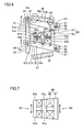
- Fig. 1 is a cross-sectional view showing an electromagnetically driven valve according to Embodiment 1 of the present invention.
- the electromagnetically driven valve according to the present embodiment implements an engine valve (an intake valve or an exhaust valve) in an internal combustion engine such as a gasoline engine or a diesel engine.
- an engine valve an intake valve or an exhaust valve
- an exhaust valve such as a gasoline engine or a diesel engine.
- description will be given assuming that the electromagnetically driven valve implements an intake valve, however, it is noted that the electromagnetically driven valve is similarly structured also when it implements an exhaust valve.
- valve guide 43 for guiding lower stem 12m is provided in cylinder head 41.
- Lower stem 12m is held by a lower retainer 46, which comes in contact with a lower spring 86. Accordingly, lower spring 86 pushes lower retainer 46 upward.
- Lash adjuster 16 is attached to lower stem 12m. Lash adjuster 16 serves to accommodate registration error of driven valve 14 at the valve-closing position, as well as to bring umbrella-shaped portion 13 into contact with valve seat 42 in an ensured manner.
- the parallel link mechanism causing lower disc 21 and upper disc 31 to simultaneously oscillate in order to allow reciprocating motion of driven valve 14 is adopted. Actually, however, registration error of driven valve 14 tends to occur due to dimension error or assembly error caused among disc parts. Therefore, providing lash adjuster 16 is particularly effective in electromagnetically driven valve 10 including the parallel link mechanism.
Landscapes
- Engineering & Computer Science (AREA)
- Mechanical Engineering (AREA)
- General Engineering & Computer Science (AREA)
- Valve Device For Special Equipments (AREA)
- Magnetically Actuated Valves (AREA)
Applications Claiming Priority (2)
| Application Number | Priority Date | Filing Date | Title |
|---|---|---|---|
| JP2004239777A JP2006057521A (ja) | 2004-08-19 | 2004-08-19 | 電磁駆動弁 |
| PCT/JP2005/011895 WO2006018931A1 (en) | 2004-08-19 | 2005-06-22 | Electromagnetically driven valve |
Publications (2)
| Publication Number | Publication Date |
|---|---|
| EP1789659A1 EP1789659A1 (en) | 2007-05-30 |
| EP1789659B1 true EP1789659B1 (en) | 2008-09-10 |
Family
ID=35044536
Family Applications (1)
| Application Number | Title | Priority Date | Filing Date |
|---|---|---|---|
| EP05780106A Expired - Lifetime EP1789659B1 (en) | 2004-08-19 | 2005-06-22 | Electromagnetically driven valve |
Country Status (6)
| Country | Link |
|---|---|
| US (1) | US20070284551A1 (https=) |
| EP (1) | EP1789659B1 (https=) |
| JP (1) | JP2006057521A (https=) |
| CN (1) | CN101061292A (https=) |
| DE (1) | DE602005009723D1 (https=) |
| WO (1) | WO2006018931A1 (https=) |
Families Citing this family (7)
| Publication number | Priority date | Publication date | Assignee | Title |
|---|---|---|---|---|
| JP4475198B2 (ja) | 2005-07-27 | 2010-06-09 | トヨタ自動車株式会社 | 電磁駆動弁 |
| JP2007040162A (ja) | 2005-08-02 | 2007-02-15 | Toyota Motor Corp | 電磁駆動弁 |
| CN1908386A (zh) | 2005-08-02 | 2007-02-07 | 丰田自动车株式会社 | 电磁驱动阀 |
| JP2007040238A (ja) | 2005-08-04 | 2007-02-15 | Toyota Motor Corp | 電磁駆動弁 |
| JP2007046498A (ja) | 2005-08-08 | 2007-02-22 | Toyota Motor Corp | 電磁駆動弁 |
| JP2007046503A (ja) | 2005-08-08 | 2007-02-22 | Toyota Motor Corp | 電磁駆動弁 |
| DE202006006825U1 (de) | 2006-04-27 | 2007-08-30 | Bürkert Werke GmbH & Co. KG | Ventil mit einem elektromagnetischen Antrieb |
Family Cites Families (12)
| Publication number | Priority date | Publication date | Assignee | Title |
|---|---|---|---|---|
| AU4237096A (en) * | 1994-11-09 | 1997-05-29 | Aura Systems, Inc. | Hinged armature electromagnetically actuated valve |
| US5765513A (en) * | 1996-11-12 | 1998-06-16 | Ford Global Technologies, Inc. | Electromechanically actuated valve |
| US6262498B1 (en) * | 1997-03-24 | 2001-07-17 | Heinz Leiber | Electromagnetic drive mechanism |
| DE19955054A1 (de) * | 1998-11-16 | 2000-08-17 | Heinz Leiber | Elektromagnetischer Antrieb |
| DE19860451A1 (de) * | 1998-12-28 | 2000-06-29 | Heinz Leiber | Antrieb für ein Ventil eines Verbrennungsmotors |
| IT1310502B1 (it) * | 1999-09-30 | 2002-02-18 | Magneti Marelli Spa | Attuatore elettromagnetico di tipo perfezionato per il comando dellevalvole di un motore a scoppio. |
| ITBO20000293A1 (it) * | 2000-05-16 | 2001-11-16 | Magneti Marelli Spa | Metodo per la protezione dal surriscaldamento di attuatori elettromagnetici per l'azionamento di valvole di aspirazione e scarico in motori |
| ITBO20000366A1 (it) * | 2000-06-23 | 2001-12-23 | Magneti Marelli Spa | Attuatore elettromagnetico per l'azionamento delle valvole di un motore a scoppio . |
| JP2002122264A (ja) * | 2000-10-12 | 2002-04-26 | Toyota Motor Corp | 電磁駆動バルブ |
| KR100401645B1 (ko) * | 2001-08-21 | 2003-10-17 | 현대자동차주식회사 | 전자 기계식 밸브 트레인 |
| DE60108767T2 (de) * | 2001-12-04 | 2005-09-22 | Ford Global Technologies, LLC (n.d.Ges.d. Staates Delaware), Dearborn | Elektromagnetischer Ventilaktuator mit Unterstützung durch Dauermagnet |
| US6763789B1 (en) * | 2003-04-01 | 2004-07-20 | Ford Global Technologies, Llc | Electromagnetic actuator with permanent magnet |
-
2004
- 2004-08-19 JP JP2004239777A patent/JP2006057521A/ja active Pending
-
2005
- 2005-06-22 WO PCT/JP2005/011895 patent/WO2006018931A1/en not_active Ceased
- 2005-06-22 DE DE602005009723T patent/DE602005009723D1/de not_active Expired - Fee Related
- 2005-06-22 CN CNA2005800276650A patent/CN101061292A/zh active Pending
- 2005-06-22 US US11/660,382 patent/US20070284551A1/en not_active Abandoned
- 2005-06-22 EP EP05780106A patent/EP1789659B1/en not_active Expired - Lifetime
Also Published As
| Publication number | Publication date |
|---|---|
| EP1789659A1 (en) | 2007-05-30 |
| CN101061292A (zh) | 2007-10-24 |
| WO2006018931A1 (en) | 2006-02-23 |
| DE602005009723D1 (de) | 2008-10-23 |
| US20070284551A1 (en) | 2007-12-13 |
| JP2006057521A (ja) | 2006-03-02 |
Similar Documents
| Publication | Publication Date | Title |
|---|---|---|
| JP3629362B2 (ja) | エンジンバルブ駆動用電磁バルブの駆動方法 | |
| EP1789659B1 (en) | Electromagnetically driven valve | |
| EP1714010B1 (en) | Electromagnetically driven valve | |
| JP2005176595A (ja) | 電磁バルブアクチュエータシステム | |
| US20070221873A1 (en) | Electromagnetically Driven Valve | |
| US7306196B2 (en) | Electromagnetically driven valve | |
| US20070290156A1 (en) | Electromagnetically Driven Valve | |
| EP1784559B1 (en) | Electromagnetically driven valve | |
| US7430996B2 (en) | Electromagnetically driven valve | |
| US20080042089A1 (en) | Electromagnetically Driven Valve | |
| US7428887B2 (en) | Electromagnetically driven valve | |
| JP2006336737A (ja) | 電磁駆動弁 | |
| JP2002071042A (ja) | 電磁駆動弁 | |
| JP2008274848A (ja) | 電磁駆動弁 | |
| JP2004285966A (ja) | 電磁駆動弁装置 | |
| JP2007154793A (ja) | 電磁駆動弁 | |
| JP2006104984A (ja) | 電磁駆動弁および内燃機関 |
Legal Events
| Date | Code | Title | Description |
|---|---|---|---|
| PUAI | Public reference made under article 153(3) epc to a published international application that has entered the european phase |
Free format text: ORIGINAL CODE: 0009012 |
|
| 17P | Request for examination filed |
Effective date: 20070220 |
|
| AK | Designated contracting states |
Kind code of ref document: A1 Designated state(s): DE FR GB |
|
| RBV | Designated contracting states (corrected) |
Designated state(s): DE FR GB |
|
| 17Q | First examination report despatched |
Effective date: 20071029 |
|
| DAX | Request for extension of the european patent (deleted) | ||
| GRAP | Despatch of communication of intention to grant a patent |
Free format text: ORIGINAL CODE: EPIDOSNIGR1 |
|
| GRAS | Grant fee paid |
Free format text: ORIGINAL CODE: EPIDOSNIGR3 |
|
| GRAA | (expected) grant |
Free format text: ORIGINAL CODE: 0009210 |
|
| AK | Designated contracting states |
Kind code of ref document: B1 Designated state(s): DE FR GB |
|
| REG | Reference to a national code |
Ref country code: GB Ref legal event code: FG4D |
|
| REF | Corresponds to: |
Ref document number: 602005009723 Country of ref document: DE Date of ref document: 20081023 Kind code of ref document: P |
|
| PLBE | No opposition filed within time limit |
Free format text: ORIGINAL CODE: 0009261 |
|
| STAA | Information on the status of an ep patent application or granted ep patent |
Free format text: STATUS: NO OPPOSITION FILED WITHIN TIME LIMIT |
|
| 26N | No opposition filed |
Effective date: 20090611 |
|
| GBPC | Gb: european patent ceased through non-payment of renewal fee |
Effective date: 20090622 |
|
| REG | Reference to a national code |
Ref country code: FR Ref legal event code: ST Effective date: 20100226 |
|
| PG25 | Lapsed in a contracting state [announced via postgrant information from national office to epo] |
Ref country code: FR Free format text: LAPSE BECAUSE OF NON-PAYMENT OF DUE FEES Effective date: 20090630 |
|
| PG25 | Lapsed in a contracting state [announced via postgrant information from national office to epo] |
Ref country code: GB Free format text: LAPSE BECAUSE OF NON-PAYMENT OF DUE FEES Effective date: 20090622 |
|
| PG25 | Lapsed in a contracting state [announced via postgrant information from national office to epo] |
Ref country code: DE Free format text: LAPSE BECAUSE OF NON-PAYMENT OF DUE FEES Effective date: 20100101 |