EP1788782B1 - Apparatus and method for header decompression - Google Patents
Apparatus and method for header decompression Download PDFInfo
- Publication number
- EP1788782B1 EP1788782B1 EP20070103500 EP07103500A EP1788782B1 EP 1788782 B1 EP1788782 B1 EP 1788782B1 EP 20070103500 EP20070103500 EP 20070103500 EP 07103500 A EP07103500 A EP 07103500A EP 1788782 B1 EP1788782 B1 EP 1788782B1
- Authority
- EP
- European Patent Office
- Prior art keywords
- header
- reference information
- error
- packet
- decompression
- Prior art date
- Legal status (The legal status is an assumption and is not a legal conclusion. Google has not performed a legal analysis and makes no representation as to the accuracy of the status listed.)
- Expired - Lifetime
Links
Images


Classifications
-
- H—ELECTRICITY
- H04—ELECTRIC COMMUNICATION TECHNIQUE
- H04L—TRANSMISSION OF DIGITAL INFORMATION, e.g. TELEGRAPHIC COMMUNICATION
- H04L69/00—Network arrangements, protocols or services independent of the application payload and not provided for in the other groups of this subclass
- H04L69/04—Protocols for data compression, e.g. ROHC
-
- H—ELECTRICITY
- H03—ELECTRONIC CIRCUITRY
- H03M—CODING; DECODING; CODE CONVERSION IN GENERAL
- H03M7/00—Conversion of a code where information is represented by a given sequence or number of digits to a code where the same, similar or subset of information is represented by a different sequence or number of digits
- H03M7/30—Compression; Expansion; Suppression of unnecessary data, e.g. redundancy reduction
-
- H—ELECTRICITY
- H04—ELECTRIC COMMUNICATION TECHNIQUE
- H04L—TRANSMISSION OF DIGITAL INFORMATION, e.g. TELEGRAPHIC COMMUNICATION
- H04L69/00—Network arrangements, protocols or services independent of the application payload and not provided for in the other groups of this subclass
- H04L69/40—Network arrangements, protocols or services independent of the application payload and not provided for in the other groups of this subclass for recovering from a failure of a protocol instance or entity, e.g. service redundancy protocols, protocol state redundancy or protocol service redirection
-
- H—ELECTRICITY
- H04—ELECTRIC COMMUNICATION TECHNIQUE
- H04L—TRANSMISSION OF DIGITAL INFORMATION, e.g. TELEGRAPHIC COMMUNICATION
- H04L9/00—Cryptographic mechanisms or cryptographic arrangements for secret or secure communications; Network security protocols
- H04L9/40—Network security protocols
-
- H—ELECTRICITY
- H04—ELECTRIC COMMUNICATION TECHNIQUE
- H04L—TRANSMISSION OF DIGITAL INFORMATION, e.g. TELEGRAPHIC COMMUNICATION
- H04L69/00—Network arrangements, protocols or services independent of the application payload and not provided for in the other groups of this subclass
- H04L69/22—Parsing or analysis of headers
Definitions
- the present invention relates to methods for header compression/decompression in packet transmission and, more specifically, to a method for header compression/decompression, where reference information is requested to be updated when an error occurs in packet transmission.
- Typical protocols recently known for data transmission over the Internet include TCP/IP (Transmission Control Protocol/Internet Protocol) and UDP/IP (User Datagram Protocol/Internet Protocol).
- TCP/IP Transmission Control Protocol/Internet Protocol
- UDP/IP User Datagram Protocol/Internet Protocol
- the header specified by TCP, UDP, IP, or other protocols is larger in size, disadvantageously causing overhead associated with communication.
- the transmitting side has to add a 28-byte header to the original data, resultantly forming a 38-byte packet, which is approximately four times larger in size than the original data. If such increase in size happens quite often, the transmission path is substantially decreased in effective speed.
- a header compression scheme developed by V. Jacobson and defined in RFC 1144 and RFC2508 has been known.
- This scheme among the fields of the header included in the packet, transmitted are only any field changed in value from the one included in the previous packet. Such field changed in value are not so many in the header, and therefore, in this scheme, header compression is successfully carried out.
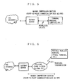
- This header compression scheme is a standard for wired communication with a low transmission error rate, as shown in FIG. 5 , and is not efficient for a transmission path with a high transmission error rate.
- FIG. 6 shows a communication network for wireless terminals over a cellular phone network such as W-CDMA.
- the communication network of FIG. 6 includes a wireless transmission section where errors frequently occur.
- ROHC RObust Header Compression
- IETF Internet Engineering Task Force
- FIG. 7 shows one example of data transmission adopting ROHC.
- the transmitting side and the receiving side each have held correct reference information ⁇ .
- the transmitting side transmits a header H1 and data D1 to the receiving side.
- the transmitting side carries out data compression on the header H1 by referring to the reference information ⁇ .
- the header H1 and a compressed header H'1 for transmission to the receiving side have such a relation as represented by the following equation (1).
- H ⁇ ⁇ 1 H ⁇ 1 * ⁇
- an operation represented by * varies for each field of the header to be compressed.
- the operation is so carried out as follows: the field does not vary if representing a UDP port number; the field is generally increased in value by 1 if representing an RTP sequence number; and the field is increased in value by 50 if representing an RTP timestamp.
- the reference information ⁇ includes all information required for compression of each field as described above. Therefore, if the receiving side holds the correct reference information ⁇ having the same contents as that held in the transmitting side, the receiving side can correctly decompress the received compressed header H'1 into the original header H1, thereby obtaining the correct header H1 and data D1. Similarly, headers and data H2 and D2, H3 and D3, and H4 and D4 are transmitted after each header is compressed by referring to the reference information ⁇ .
- FIG. 8 shows an example of data transmission where the reference information is changed during the transmission.
- the reference information is changed from ⁇ to ⁇ , and the header H3 is compressed by referring to the changed reference information ⁇ .
- the transmitting side changes the reference information ⁇ held so far containing that "The RTP timestamp is increased by 50" into the reference information ⁇ containing that "The RTP timestamp is increased by 100".
- the receiving side refers to update information further provided to the compressed header to be transmitted (here, a header H'3).
- the reference information may be updated even if the update information is not explicitly transmitted.
- One example header compression scheme taken in such cases is briefly described below.
- the sequence number is assigned 4 bits capable of representing integers from 0 to 15, but not 16 or more. Therefore, any integer N equal to 16 or more is represented by Nmod16.
- the receiving side finds the sequence number by using an equation L *16 + (received sequence number), where L is incremented by 1 whenever the received sequence number is changed from the maximum value (here, 15) to the minimum value (here, 0).
- the update information is not explicitly transmitted. Instead, when the sequence number becomes larger than the maximum value, the reference information is updated on both sides.
- FIG. 9 is a block diagram showing the structure of a header decompression apparatus that achieves the header decompression as described above.
- a header decompression apparatus 1007 includes a packet output unit 1001, an error detector 1002, a header decompressor 1003, a packet receiver 1004, a reference information manager 1005, and an update request unit 1006.
- the packet receiver 1004 receives a header-compressed packet from a transmitting side, and outputs the packet to the header decompressor 1003.
- the header decompressor 1003 refers to reference information managed by the reference information manager 1005 to decompress the compressed header, and outputs the header-decompressed packet to the error detector 1002. If the compressed header is provided with update information, the header decompressor 1003 updates the reference information managed by the reference information manager 1005 with the update information provided to the compressed header.
- the error detector1002 detects any error in the header-decompressed packet. If not detecting an error, the error detector 1002 outputs the correctly-decompressed packet to the packet output unit 1001. If detecting an error, the error detector 1002 discards the packet as not having been correctly decompressed.
- the update request unit 1006 receives a notification that an error is detected by the error detector 1002, and transmits an update request to the transmitting side. Specifically, according to the above document, "draft-ietf-rohc-rtp-00.txt (29 June 2000)", the update request unit 1006 transmits a NACK packet.
- the reference information manager 1005 manages the reference information for header decompression.
- the packet output unit 1001 outputs the header-decompressed packet.
- the header decompression apparatus 1007 detects any error in the compressed header.
- the compressed header is provided with a CRC (Cyclic Redundancy Code) for determining whether the header-decompressed packet has any error or not. Therefore, any error that occurred in the compressed header or a payload due to noise during wireless transmission can be detected, and the erroneous packet can be discarded.
- CRC Cyclic Redundancy Code
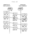
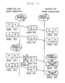
- FIG. 10 shows one example of data transmission where an error occurs due to noise during wireless transmission.
- a header H2 is compressed to be a header H'2 , and the header H'2 and data D2 are wirelessly transmitted.
- noise or other factors affect the compressed header H'2 , causing an error, which is denoted by a dotted cross in FIG. 10 .
- a solid cross in FIG. 10 the header cannot be correctly decompressed at the receiving side, and therefore the entire packet is discarded.
- FIG. 11 exemplarily shows a case where an error occurs in the header with the update information provided thereto, and the reference information is erroneously updated.
- a header H3 is compressed to be a header H'3
- the header H'3 and data D3 is wirelessly transmitted.
- noise or other factors affect the update information provided to the compressed header H'3 , causing a change in the update information, which is denoted by a dotted cross in FIG. 11 .
- the reference information is erroneously updated to reference information ⁇ ', based on the changed update information, and the header H3 decompressed by referring to the erroneous reference information is not the same as the original header H3 before compression at the transmitting side.
- This also applies to the following headers H4 and thereafter.
- the header cannot correctly decompressed at the receiving side, and is generally regarded as having an error. Therefore, the entire packet is discarded.
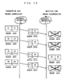
- FIG. 12 exemplarily shows a case where a packet is not regarded as having an error even if the reference information is erroneously updated.
- the reference information is erroneously updated at the receiving side to become receiving-side reference information a', which is different from the reference information ⁇ at the transmitting side.
- headers H1 to H4 are erroneously decompressed at the receiving side. Therefore, in general, CRC errors occur and the entire packet are discarded.
- an object of the present invention is to provide a header decompression method in which only a necessary request for updating reference information is made based on the state of an error in a header-decompressed packet.
- a header decompression apparatus is suitable for decompressing a compressed header of a packet for transmission by referring to reference information being the same as reference information referred to for header compression by a transmitting side.
- a packet receiver receives the packet from the transmitting side.
- a reference information manager stores and manages the reference information.
- a header decompressor is provided with the received packet, and carries out header decompression by referring to the reference information stored in the reference information manager.
- An error detector detects an error in the packet including the decompressed header.
- a counter/storage counts and stores the number of errors detected by the error detector.
- An update request unit transmits, to the transmitting side, update information for updating the reference information, when determining, based on the number counted by the counter/storage, that the reference information stored in the reference information manager should be updated.
- the reference information manager updates the reference information stored in the reference information manager based on the transmitted update information.
- the update request unit determines whether the reference information should be updated.
- the number of packets to be discarded due to error in the reference information can be reduced, and efficient packet transmission can be achieved.
- the counter/storage includes a successive error counter and a successive decompression success counter.
- the successive error counter counts and stores the number of times X the packet having the error detected by the error detector successively appeared.
- the successive decompression success counter counts and stores the number of times Y the packet having no error successively appeared after the error detector detects the error.
- the update request unit determines, based on values of X and Y counted by the counter/storage, whether the reference information stored in the reference information manager should be updated.
- the update request unit determines that the reference information stored in the reference information manager should be updated.
- the counter/storage counts and stores the number of packets W previously received and the number of packets R having the error detected by the error detector.
- the update request unit determines, based on W and R counted by the counter/storage, that the reference information stored in the reference information manager should be updated when R is larger than a predetermined value.
- the fourth example if the number of decompression errors in the packets previously received at the receiving side becomes large, an update request is sent to the transmitting side.
- the number of packets to be discarded due to error in the reference information can be reduced, and efficient packet transmission can be achieved.
- Fifth to eighth examples are directed to header decompression methods respectively corresponding to the above header decompression apparatuses.
- Ninth to eleventh examples are directed to computer-readable recording media with programs respectively corresponding the above header decompression methods.
- Twelfth to fourteenth examples are directed to programs respectively corresponding to the above header decompression methods.
- a method for header compression/decompression according to a first embodiment of the present invention is realized by a header compression apparatus and a header decompression apparatus as shown in FIGS. 1 and 2 , respectively.
- FIGS. 1 and 2 the structure of each apparatus is described below.
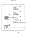
- FIG. 1 is a block diagram showing the structure of a header compression apparatus 607.
- the header compression apparatus 607 includes a packet input unit 601, a CRC provider 602, a header compressor 603, a packet transmitter 604, a reference information manager 605, and an update request receiver 606.
- the packet input unit 601 outputs a received packet to the CRC provider 602.
- the CRC provider 602 provides the received packet with a CRC for output to the header compressor 603.
- the header compressor 603 refers to reference information managed by the reference information manager 605 to compress the header of the received packet, and outputs the resultant packet to the packet transmitter 604. How to compress the header will be described later.
- the packet transmitter 604 transmits the received header-compressed packet to the receiving side.
- the reference information manager 605 manages the reference information referred to by the header compressor 603.
- the update request receiver 606 receives an update request from the transmitting side, and notifies the reference information manager 605 of the update request.
- the notified reference information manager 605 outputs the managed reference information to the header compressor 603, and instructs it to provide update information corresponding to the reference information to the compressed header.
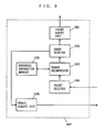
- FIG. 2 is a block diagram showing the structure of a header decompression apparatus 709.
- the header decompression apparatus 709 includes a packet output unit 701, an error detector 702, a header decompressor 703, a packet receiver 704, a successive decompression error counter (hereinafter, successive error counter) 705, a successive decompression success counter 706, a reference information manager 707, and an update request unit 708.
- successive error counter successive decompression error counter
- the packet receiver 704 receives, from the transmitting side, the header-compressed packet, and outputs it to the header decompressor 703.
- the header decompressor 703 refers to the reference information managed by the reference information manager 707 to decompress the compressed header, and outputs the resultant packet to the error detector 702.
- the error detector 702 detects a CRC error in the header-decompressed packet, and outputs, to the packet output unit 701, only any packet whose header has been correctly decompressed.
- the successive error counter 705 counts the number of successive decompression errors detected by the error detector 702.
- the successive decompression success counter 706 counts the number of successive decompression successes detected by the error detector 702.
- the update request unit 708 refers to the numbers counted by the successive error counter 705 and the successive decompression success counter 706 to determine whether an update request is required or not in a manner described later, and transmits the update request as required to the transmitting side.
- the reference information manager 707 manages the reference information for header decompression.
- uccessive decompression errors mean that successive two or more error states are observed in a header, or that only one error state is observed therein, although the latter is not generally applicable to the meaning of the word "successive”.
- successive decompression successes means that successive two or more error-free states are observed in a header, or that only one error-free state is observed therein. How to determine "successive" states in the present invention will be described later.
- a packet supplied to the apparatuses contains data, such as video and audio, with an RTP/UDP/IP header.
- the packet input part 601 outputs an externally-inputted RTP/UDP/IP packet to the CRC provider 602.
- the CRC provider 602 computes a CRC for the entire packet, and provides the CRC to the packet.
- the header compressor 603 refers to the reference information managed by the reference information manager 605 for header compression. In this header compression, if the header can be decompressed with its sequence number, the reference information is not updated, and only the sequence number is included in the header. If the header cannot be decompressed with its sequence number, update information of the reference information and the sequence number are included in the header.
- the packet transmitter 604 transmits the header-compressed packet to the receiving side.
- the reference information manager 605 stores and manages the reference information referred to by the header compressor 603. Notified by the header compressor 603 of update, the reference information manager 605 updates the stored reference information. Notified by the update request receiver 606 that an update request has been received, the reference information manager 605 instructs the header compressor 603 to provide the update information to the header.
- the update request receiver 606 receives an update request from the receiving side. On receiving the update request, the update request receiver 606 notifies the reference information manager 605 that the update request has been received.
- the packet receiver 704 receives the header-compressed packet transmitted from the packet transmitter 604 shown in FIG. 1 , and outputs the packet to the header decompressor 703.
- the header decompressor 703 refers to the reference information stored in the reference information manager 707 to decompress the compressed-header of the packet.
- the header-decompressed packet is outputted to the error detector 702. If the header is provided with update information, the header decompressor 703 notifies the reference information manager 707 of the update information.
- the error detector 702 checks whether any error occurs or not in the header-decompressed packet by using the CRC. Also, the error detector 702 notifies the successive error counter 705 and the successive decompression success counter 706 of the presence or absence of an error. If detecting any error, the error detector 702 discards the packet. If not detecting, the error detector 702 outputs, to the packet output unit 701, the packet with the CRC removed therefrom. The packet output unit 701 externally outputs the error-undetected RTP/UDP/IP packet.
- the reference information manager 707 stores and manages the reference information required for header decompression. If the compressed header includes the update information, the reference information manager 707 updates the stored reference information with the update information coming from the header decompressor 703.
- the successive error counter 705 counts the number of successive errors X based on the error detection results in the error detector 702. For example, if an error is detected in a packet, X is 1. Then, if an error is detected also in the next packet, X becomes 2. Then, if an error is detected still in the following packet, X is further incremented by 1 to become 3. If no error is detected, successiveness is interrupted, and the error counter 705 stops counting.
- the successive decompression success counter 706 counts the number of decompression successes Y based on the error detection results in the error detector 702. For example, if no error is detected in a packet, Y is 1. Then, if no error is detected also in the next packet, Y becomes 2. Then, if no error is detected still in the following packet, Y is further incremented by 1 to become 3. If any error is detected, successiveness is interrupted, and the successive decompression success counter 706 stops counting.
- the update request unit 708 determines whether to request update based on a set of X outputted from the successive error counter 705 and Y outputted from the successive decompression success counter 706. This determination operation is further described in detail with reference to FIG. 3 .
- FIG. 3 is a diagram exemplarily showing decompression operation and values of X and Y when packets P1 to P11 are received. In FIG. 3 , assume that an error occurred in a packet P12 not shown.
- the update request unit 708 regards the values of X and Y as a set representing successive decompression errors and subsequent decompression successes, and compares these values with predetermined values.
- predetermined values are example only, and not restrictive. If X ⁇ Y, a large number of successive decompression errors have occurred, and therefore there is a high possibility that the reference information has an error.
- the header decompression apparatus 709 requests the transmitting side of updating the reference information based on the number of successive decompression errors and successes at the receiving side.
- the number of packets discarded due to error in the reference information can be reduced, and efficient packet transmission can be achieved.
- Such capability of the header decompression apparatus 709 can be achieved in a general-purpose computer system. In this case, this capability is realized by a program executed in the computer system. The program is typically stored in a recoding medium such as CD-ROM, or transmitted through a communication medium.
- a method for header compression/decompression according to a second embodiment of the present invention is realized by a header compression apparatus and a header decompression apparatus as shown in FIGS. 1 and 4 , respectively. Therefore, the header compression apparatus according to the second embodiment is the same in structure as the header compression apparatus 607 shown in FIG. 1 , and not described herein. Described below is the structure of the header decompression apparatus according to the present embodiment with reference to FIG. 4 .
- FIG. 4 is a block diagram showing the structure of a header decompression apparatus 908.
- the header decompression apparatus 908 includes a packet output unit 901, an error detector 902, a header decompressor 903, a packet receiver 904, a decompression error detection result storage 905, a reference information manager 906, and an update request unit 907.
- the packet receiver 904 outputs a header-compressed packet supplied from the transmitting side to the header decompressor 903.
- the header decompressor 903 refers to the reference information in the reference information manager 906 to decompress the compressed header, and outputs the resultant packet to the error detector 902.
- the error detector 902 detects any error in the header-decompressed packet, and outputs, to the packet output unit 901, any packet whose header has been correctly decompressed.
- the decompression error detection result storage 905 counts the number of errors or successes detected in the packet by the error detector 902 for storage.
- the update request unit 907 is supplied with the number counted by the decompression error detection result storage 905, determining whether an update request is required or not and transmitting the update request as required to the transmitting side.
- the reference information manager 906 manages the reference information for header decompression.
- Described specifically below is the operation of the above structured header decompression apparatus according to the present embodiment.
- the operation of the header compression apparatus 607 that is, the transmitting side, is similar to that according to the first embodiment.
- a packet supplied to the apparatuses contains data such as video and audio with an RTP/UDP/IP header.
- a packet receiver 904 receives a header-compressed packet transmitted from the packet transmitter 604 of FIG. 1 , and outputs the packet to the header decompressor 903.
- the header decompressor 903 refers to the reference information stored in the reference information manager 906 to decompress the compressed-header of the packet.
- the header-decompressed packet is outputted to the error detector 902. If the header is provided with update information of the reference information, the header decompressor 903 outputs the update information to the reference information manager 906.
- the error detector 902 checks the presence or absence of an error in the header-decompressed packet by using the CRC. Also, the error detector 902 notifies the detection result to the decompression error detection result storage 905. If detecting any error, the error detector 902 discards the packet. If not detecting, the error detector 902 outputs, to the packet output unit 901, the packet with the CRC removed therefrom. The packet output unit 901 externally outputs the error-undetected RTP/UDP/IP packet.
- the reference information manager 906 stores and manages the reference information required for header decompression. If the compressed header includes the update information, the reference information manager 906 updates the stored reference information with the update information coming from the header decompressor 903.
- the decompression error detection result storage 905 stores the detection results of the error detector 902, that is, the number of errors R for preceding W packets. Instead of W or R, the number of decompression successes may be stored.
- the header decompression apparatus 908 requests updating of the reference information when the number of decompression errors becomes relatively or substantially large in the packets previously received by the receiving side.
- the number of packets discarded due to error in the reference information can be reduced, and efficient packet transmission can be achieved.
- Such capability of the header decompression apparatus 908 can be achieved in a general-purpose computer system. In this case, this capability is realized by a program executed in the computer system. The program is typically stored in a recoding medium such as CD-ROM, or transmitted through a communication medium.
Landscapes
- Engineering & Computer Science (AREA)
- Computer Security & Cryptography (AREA)
- Computer Networks & Wireless Communication (AREA)
- Signal Processing (AREA)
- Theoretical Computer Science (AREA)
- Data Exchanges In Wide-Area Networks (AREA)
- Detection And Prevention Of Errors In Transmission (AREA)
- Communication Control (AREA)
- Maintenance And Management Of Digital Transmission (AREA)
Applications Claiming Priority (4)
| Application Number | Priority Date | Filing Date | Title |
|---|---|---|---|
| JP2000274615 | 2000-09-11 | ||
| JP2000367514A JP4592935B2 (ja) | 2000-09-11 | 2000-12-01 | ヘッダ復元装置およびヘッダ復元方法 |
| EP20040009502 EP1447956B1 (en) | 2000-09-11 | 2001-09-07 | Apparatus and method for header decompression |
| EP20010120765 EP1191760B1 (en) | 2000-09-11 | 2001-09-07 | Apparatus and method for header decompression |
Related Parent Applications (3)
| Application Number | Title | Priority Date | Filing Date |
|---|---|---|---|
| EP01120765.1 Division | 2001-09-07 | ||
| EP20040009502 Division EP1447956B1 (en) | 2000-09-11 | 2001-09-07 | Apparatus and method for header decompression |
| EP04009502.8 Division | 2004-04-22 |
Publications (3)
| Publication Number | Publication Date |
|---|---|
| EP1788782A2 EP1788782A2 (en) | 2007-05-23 |
| EP1788782A3 EP1788782A3 (en) | 2007-07-25 |
| EP1788782B1 true EP1788782B1 (en) | 2013-12-04 |
Family
ID=26599627
Family Applications (3)
| Application Number | Title | Priority Date | Filing Date |
|---|---|---|---|
| EP20070103500 Expired - Lifetime EP1788782B1 (en) | 2000-09-11 | 2001-09-07 | Apparatus and method for header decompression |
| EP20010120765 Expired - Lifetime EP1191760B1 (en) | 2000-09-11 | 2001-09-07 | Apparatus and method for header decompression |
| EP20040009502 Expired - Lifetime EP1447956B1 (en) | 2000-09-11 | 2001-09-07 | Apparatus and method for header decompression |
Family Applications After (2)
| Application Number | Title | Priority Date | Filing Date |
|---|---|---|---|
| EP20010120765 Expired - Lifetime EP1191760B1 (en) | 2000-09-11 | 2001-09-07 | Apparatus and method for header decompression |
| EP20040009502 Expired - Lifetime EP1447956B1 (en) | 2000-09-11 | 2001-09-07 | Apparatus and method for header decompression |
Country Status (6)
| Country | Link |
|---|---|
| US (3) | US6959410B2 (enExample) |
| EP (3) | EP1788782B1 (enExample) |
| JP (1) | JP4592935B2 (enExample) |
| CN (2) | CN1645864B (enExample) |
| CA (1) | CA2357223C (enExample) |
| DE (3) | DE60112525T2 (enExample) |
Families Citing this family (27)
| Publication number | Priority date | Publication date | Assignee | Title |
|---|---|---|---|---|
| JP3323483B2 (ja) * | 2000-09-12 | 2002-09-09 | 松下電器産業株式会社 | パケット送信装置およびパケット伝送方法 |
| JP3617967B2 (ja) * | 2001-09-28 | 2005-02-09 | 松下電器産業株式会社 | ヘッダ圧縮パケット受信装置及び方法 |
| US7055085B2 (en) * | 2002-03-07 | 2006-05-30 | Broadcom Corporation | System and method for protecting header information using dedicated CRC |
| EP1349285A1 (en) * | 2002-03-28 | 2003-10-01 | Matsushita Electric Industrial Co., Ltd. | Method for making efficient use of the bits allocated to the sequence number when transmitting compressed header data |
| US7359372B2 (en) * | 2002-06-12 | 2008-04-15 | Telefonaktibolaget Lm Ericsson (Publ) | Method and apparatus for fast change of internet protocol headers compression mechanism |
| JP2006514467A (ja) * | 2003-02-11 | 2006-04-27 | ユニシス コーポレイシヨン | コントロールファイルを更新するための方法および装置 |
| US20040165585A1 (en) * | 2003-02-25 | 2004-08-26 | Koji Imura | Packet transmission apparatus and packet transmission method |
| US7443785B2 (en) * | 2004-03-17 | 2008-10-28 | Sony Ericsson Mobile Communications Ab | Selective error correction for ad hoc networks having multiple communication modes |
| US20060029367A1 (en) * | 2004-08-03 | 2006-02-09 | Takuya Kosugi | Sequence header identification |
| US7924731B2 (en) * | 2004-11-15 | 2011-04-12 | Telefonaktiebolaget Lm Ericsson (Publ) | Method and apparatus for handling out-of-sequence packets in header decompression |
| US8165104B2 (en) * | 2004-12-08 | 2012-04-24 | Qualcomm Incorporated | Methods and systems for enhancing local repair in robust header compression |
| US20060277322A1 (en) * | 2005-06-03 | 2006-12-07 | Nokia Corporation | System and method for implementing reference-based electronic mail compression |
| US8804765B2 (en) * | 2005-06-21 | 2014-08-12 | Optis Wireless Technology, Llc | Dynamic robust header compression |
| US7916750B2 (en) * | 2005-12-28 | 2011-03-29 | Intel Corporation | Transaction layer packet compression |
| US7948989B2 (en) * | 2006-05-04 | 2011-05-24 | Qualcomm, Incorporated | Methods and systems for enhancing local repair in robust header compression |
| US8488583B2 (en) * | 2007-03-16 | 2013-07-16 | Telefonaktiebolaget L M Ericsson (Publ) | Method and apparatus for relocating a header compression context in a wireless communication system |
| US8423789B1 (en) | 2007-05-22 | 2013-04-16 | Marvell International Ltd. | Key generation techniques |
| EP2209265B1 (en) | 2007-10-31 | 2015-08-26 | Fujitsu Limited | Communication method and communication terminal, data transfer device, and controller |
| JP5195762B2 (ja) * | 2007-12-03 | 2013-05-15 | 富士通株式会社 | パケット通信装置及びパケット通信方法 |
| WO2010024114A1 (ja) | 2008-08-25 | 2010-03-04 | 日本電気株式会社 | 通信装置およびヘッダ圧縮制御方法 |
| US8874793B2 (en) * | 2009-11-30 | 2014-10-28 | Qualcomm Innovation Center, Inc. | Methods and apparatus for improving header compression |
| JP5609728B2 (ja) * | 2011-03-18 | 2014-10-22 | 富士通株式会社 | 通信端末およびデータ転送方法 |
| CN106664288A (zh) * | 2014-08-15 | 2017-05-10 | 瑞典爱立信有限公司 | 突发丢失的RoHC优化 |
| CN105764092A (zh) * | 2014-12-17 | 2016-07-13 | 中兴通讯股份有限公司 | 初始状态报文发送控制方法、压缩端、解压端设备及系统 |
| WO2017029809A1 (ja) * | 2015-08-19 | 2017-02-23 | 日本電気株式会社 | エラー監視装置、方法および記録媒体 |
| EP3419252A4 (en) * | 2016-02-15 | 2019-08-14 | Nec Corporation | WIRELESS BASE STATION, TERMINAL DEVICE AND COMMUNICATION SYSTEM |
| CN107919935B (zh) * | 2016-10-08 | 2022-04-15 | 中兴通讯股份有限公司 | 一种提高语音通信质量的方法及装置 |
Family Cites Families (10)
| Publication number | Priority date | Publication date | Assignee | Title |
|---|---|---|---|---|
| JPH06268633A (ja) | 1993-03-15 | 1994-09-22 | Fujitsu Ltd | データ多重保護方法及び回路 |
| US5410546A (en) * | 1993-11-01 | 1995-04-25 | Storage Technology Corporation | Apparatus and method for CRC computation over fixed length blocks containing variable length packets of data received out of order |
| US6449352B1 (en) * | 1995-06-20 | 2002-09-10 | Matsushita Electric Industrial Co., Ltd. | Packet generating method, data multiplexing method using the same, and apparatus for coding and decoding of the transmission data |
| JP3323057B2 (ja) * | 1996-04-10 | 2002-09-09 | 沖電気工業株式会社 | 符号化装置、復号化装置及び伝送システム |
| US6148422A (en) * | 1997-10-07 | 2000-11-14 | Nortel Networks Limited | Telecommunication network utilizing an error control protocol |
| WO1999034550A1 (en) * | 1997-12-26 | 1999-07-08 | Matsushita Electric Industrial Co., Ltd. | Apparatus for reproduction of encoded signal |
| JP3196839B2 (ja) | 1998-09-28 | 2001-08-06 | 日本電気株式会社 | 移動通信システムにおける無線品質劣化判定方法及び無線品質監視装置 |
| US6556587B1 (en) * | 1999-02-26 | 2003-04-29 | Telefonaktiebolaget Lm Ericsson (Publ) | Update of header compression state in packet communications |
| WO2000051307A1 (en) * | 1999-02-26 | 2000-08-31 | Telefonaktiebolaget Lm Ericsson (Publ) | Adaptive header compression for packet communications |
| US6609224B1 (en) * | 2000-02-04 | 2003-08-19 | Telefonaktiebolaget Lm Ericsson (Publ) | Replacement of transport-layer checksum in checksum-based header compression |
-
2000
- 2000-12-01 JP JP2000367514A patent/JP4592935B2/ja not_active Expired - Lifetime
-
2001
- 2001-09-07 DE DE2001612525 patent/DE60112525T2/de not_active Expired - Lifetime
- 2001-09-07 EP EP20070103500 patent/EP1788782B1/en not_active Expired - Lifetime
- 2001-09-07 DE DE2001628409 patent/DE60128409T2/de not_active Expired - Lifetime
- 2001-09-07 EP EP20010120765 patent/EP1191760B1/en not_active Expired - Lifetime
- 2001-09-07 DE DE20122718U patent/DE20122718U1/de not_active Expired - Lifetime
- 2001-09-07 EP EP20040009502 patent/EP1447956B1/en not_active Expired - Lifetime
- 2001-09-10 US US09/948,765 patent/US6959410B2/en not_active Ceased
- 2001-09-10 CA CA 2357223 patent/CA2357223C/en not_active Expired - Lifetime
- 2001-09-11 CN CN2005100525960A patent/CN1645864B/zh not_active Expired - Lifetime
- 2001-09-11 CN CNB01133049XA patent/CN1198403C/zh not_active Expired - Lifetime
-
2004
- 2004-03-19 US US10/803,906 patent/US7000166B2/en not_active Expired - Lifetime
-
2007
- 2007-10-24 US US11/976,453 patent/USRE43100E1/en not_active Expired - Lifetime
Also Published As
| Publication number | Publication date |
|---|---|
| CN1645864A (zh) | 2005-07-27 |
| US7000166B2 (en) | 2006-02-14 |
| EP1447956A3 (en) | 2004-09-08 |
| EP1191760A2 (en) | 2002-03-27 |
| CN1645864B (zh) | 2010-05-05 |
| DE20122718U1 (de) | 2007-03-22 |
| JP4592935B2 (ja) | 2010-12-08 |
| DE60128409D1 (de) | 2007-06-21 |
| DE60112525D1 (de) | 2005-09-15 |
| EP1788782A2 (en) | 2007-05-23 |
| CN1344069A (zh) | 2002-04-10 |
| USRE43100E1 (en) | 2012-01-10 |
| DE60128409T2 (de) | 2008-01-10 |
| US20040181741A1 (en) | 2004-09-16 |
| EP1191760A3 (en) | 2003-09-17 |
| JP2002158739A (ja) | 2002-05-31 |
| US6959410B2 (en) | 2005-10-25 |
| EP1447956A2 (en) | 2004-08-18 |
| DE60112525T2 (de) | 2006-06-08 |
| US20020031149A1 (en) | 2002-03-14 |
| EP1788782A3 (en) | 2007-07-25 |
| EP1191760B1 (en) | 2005-08-10 |
| CA2357223A1 (en) | 2002-03-11 |
| CA2357223C (en) | 2006-01-17 |
| CN1198403C (zh) | 2005-04-20 |
| EP1447956B1 (en) | 2007-05-09 |
Similar Documents
| Publication | Publication Date | Title |
|---|---|---|
| EP1788782B1 (en) | Apparatus and method for header decompression | |
| EP1180871B1 (en) | Method and apparatus for header compression | |
| EP1261184B1 (en) | Method and device for error correction in the static header information of a received packet | |
| EP1271886B1 (en) | Packet header compression | |
| EP1187416B1 (en) | Method and apparatus for transmitting data packets | |
| EP2190162A1 (en) | Method and device for decoding by using wlsb in robust header compression | |
| US20030198250A1 (en) | Method, apparatus and system for transmitting compressed header data | |
| EP1482668A1 (en) | PACKET TRANSMITTER, PACKET RECEIVER AND PACKET TRANSMISSION METHOD | |
| WO2000079764A1 (en) | Robust delta encoding with history information | |
| US20040165542A1 (en) | Packet transmitter and packet transmitter method | |
| JP3638939B2 (ja) | ヘッダ復元装置およびヘッダ復元方法 | |
| JP3638940B2 (ja) | ヘッダ復元装置およびヘッダ復元方法 | |
| US20040136380A1 (en) | Packet transmitter, packet receiver and packet transmission method | |
| EP1482700A1 (en) | Packet transmitter and packet transmission method |
Legal Events
| Date | Code | Title | Description |
|---|---|---|---|
| PUAI | Public reference made under article 153(3) epc to a published international application that has entered the european phase |
Free format text: ORIGINAL CODE: 0009012 |
|
| AC | Divisional application: reference to earlier application |
Ref document number: 1191760 Country of ref document: EP Kind code of ref document: P Ref document number: 1447956 Country of ref document: EP Kind code of ref document: P |
|
| AK | Designated contracting states |
Kind code of ref document: A2 Designated state(s): DE FI FR GB SE |
|
| PUAL | Search report despatched |
Free format text: ORIGINAL CODE: 0009013 |
|
| AK | Designated contracting states |
Kind code of ref document: A3 Designated state(s): DE FI FR GB SE |
|
| 17P | Request for examination filed |
Effective date: 20070810 |
|
| AKX | Designation fees paid |
Designated state(s): DE FI FR GB SE |
|
| RAP1 | Party data changed (applicant data changed or rights of an application transferred) |
Owner name: PANASONIC CORPORATION |
|
| 17Q | First examination report despatched |
Effective date: 20100415 |
|
| GRAP | Despatch of communication of intention to grant a patent |
Free format text: ORIGINAL CODE: EPIDOSNIGR1 |
|
| RIC1 | Information provided on ipc code assigned before grant |
Ipc: H04L 29/14 20060101ALI20130613BHEP Ipc: H04L 29/06 20060101AFI20130613BHEP |
|
| INTG | Intention to grant announced |
Effective date: 20130705 |
|
| RIN1 | Information on inventor provided before grant (corrected) |
Inventor name: IDO DAIJI Inventor name: HATA KOICHI Inventor name: IMURA KOJI Inventor name: MIYAZAKI AKIHIRO |
|
| GRAS | Grant fee paid |
Free format text: ORIGINAL CODE: EPIDOSNIGR3 |
|
| GRAA | (expected) grant |
Free format text: ORIGINAL CODE: 0009210 |
|
| AC | Divisional application: reference to earlier application |
Ref document number: 1447956 Country of ref document: EP Kind code of ref document: P Ref document number: 1191760 Country of ref document: EP Kind code of ref document: P |
|
| AK | Designated contracting states |
Kind code of ref document: B1 Designated state(s): DE FI FR GB SE |
|
| REG | Reference to a national code |
Ref country code: GB Ref legal event code: FG4D |
|
| REG | Reference to a national code |
Ref country code: DE Ref legal event code: R082 Ref document number: 60148479 Country of ref document: DE Representative=s name: GRUENECKER, KINKELDEY, STOCKMAIR & SCHWANHAEUS, DE |
|
| REG | Reference to a national code |
Ref country code: DE Ref legal event code: R096 Ref document number: 60148479 Country of ref document: DE Effective date: 20140130 |
|
| RAP2 | Party data changed (patent owner data changed or rights of a patent transferred) |
Owner name: GODO KAISHA IP BRIDGE 1 |
|
| REG | Reference to a national code |
Ref country code: DE Ref legal event code: R082 Ref document number: 60148479 Country of ref document: DE Representative=s name: GRUENECKER PATENT- UND RECHTSANWAELTE PARTG MB, DE Effective date: 20140128 Ref country code: DE Ref legal event code: R082 Ref document number: 60148479 Country of ref document: DE Representative=s name: GRUENECKER, KINKELDEY, STOCKMAIR & SCHWANHAEUS, DE Effective date: 20140128 Ref country code: DE Ref legal event code: R081 Ref document number: 60148479 Country of ref document: DE Owner name: GODO KAISHA IP BRIDGE 1, JP Free format text: FORMER OWNER: PANASONIC CORPORATION, KADOMA-SHI, OSAKA, JP Effective date: 20140128 Ref country code: DE Ref legal event code: R081 Ref document number: 60148479 Country of ref document: DE Owner name: GODO KAISHA IP BRIDGE 1, JP Free format text: FORMER OWNER: MATSUSHITA ELECTRIC INDUSTRIAL CO., LTD., KADOMA-SHI, OSAKA, JP Effective date: 20131206 Ref country code: DE Ref legal event code: R081 Ref document number: 60148479 Country of ref document: DE Owner name: GODO KAISHA IP BRIDGE 1, JP Free format text: FORMER OWNER: PANASONIC CORP., KADOMA-SHI, JP Effective date: 20140128 Ref country code: DE Ref legal event code: R081 Ref document number: 60148479 Country of ref document: DE Owner name: GODO KAISHA IP BRIDGE 1, JP Free format text: FORMER OWNER: MATSUSHITA ELECTRIC INDUSTRIAL CO., LTD., KADOMA-SHI, JP Effective date: 20131206 |
|
| REG | Reference to a national code |
Ref country code: GB Ref legal event code: 732E Free format text: REGISTERED BETWEEN 20140220 AND 20140226 |
|
| REG | Reference to a national code |
Ref country code: SE Ref legal event code: TRGR |
|
| REG | Reference to a national code |
Ref country code: DE Ref legal event code: R097 Ref document number: 60148479 Country of ref document: DE |
|
| PLBE | No opposition filed within time limit |
Free format text: ORIGINAL CODE: 0009261 |
|
| STAA | Information on the status of an ep patent application or granted ep patent |
Free format text: STATUS: NO OPPOSITION FILED WITHIN TIME LIMIT |
|
| 26N | No opposition filed |
Effective date: 20140905 |
|
| REG | Reference to a national code |
Ref country code: DE Ref legal event code: R097 Ref document number: 60148479 Country of ref document: DE Effective date: 20140905 |
|
| REG | Reference to a national code |
Ref country code: FR Ref legal event code: PLFP Year of fee payment: 16 |
|
| REG | Reference to a national code |
Ref country code: FR Ref legal event code: PLFP Year of fee payment: 17 |
|
| REG | Reference to a national code |
Ref country code: FR Ref legal event code: PLFP Year of fee payment: 18 |
|
| PGFP | Annual fee paid to national office [announced via postgrant information from national office to epo] |
Ref country code: DE Payment date: 20200925 Year of fee payment: 20 Ref country code: FI Payment date: 20200921 Year of fee payment: 20 Ref country code: FR Payment date: 20200914 Year of fee payment: 20 Ref country code: GB Payment date: 20200922 Year of fee payment: 20 |
|
| REG | Reference to a national code |
Ref country code: DE Ref legal event code: R039 Ref document number: 60148479 Country of ref document: DE Ref country code: DE Ref legal event code: R008 Ref document number: 60148479 Country of ref document: DE |
|
| PGFP | Annual fee paid to national office [announced via postgrant information from national office to epo] |
Ref country code: SE Payment date: 20200925 Year of fee payment: 20 |
|
| REG | Reference to a national code |
Ref country code: DE Ref legal event code: R082 Ref document number: 60148479 Country of ref document: DE Representative=s name: HOFFMANN - EITLE PATENT- UND RECHTSANWAELTE PA, DE |
|
| REG | Reference to a national code |
Ref country code: DE Ref legal event code: R071 Ref document number: 60148479 Country of ref document: DE |
|
| REG | Reference to a national code |
Ref country code: GB Ref legal event code: PE20 Expiry date: 20210906 |
|
| REG | Reference to a national code |
Ref country code: FI Ref legal event code: MAE |
|
| PG25 | Lapsed in a contracting state [announced via postgrant information from national office to epo] |
Ref country code: GB Free format text: LAPSE BECAUSE OF EXPIRATION OF PROTECTION Effective date: 20210906 |
|
| REG | Reference to a national code |
Ref country code: DE Ref legal event code: R040 Ref document number: 60148479 Country of ref document: DE |