EP1788597A1 - Elektrowerkzeug, insbesondere Akku-Elektrowerkzeug - Google Patents
Elektrowerkzeug, insbesondere Akku-Elektrowerkzeug Download PDFInfo
- Publication number
- EP1788597A1 EP1788597A1 EP06023399A EP06023399A EP1788597A1 EP 1788597 A1 EP1788597 A1 EP 1788597A1 EP 06023399 A EP06023399 A EP 06023399A EP 06023399 A EP06023399 A EP 06023399A EP 1788597 A1 EP1788597 A1 EP 1788597A1
- Authority
- EP
- European Patent Office
- Prior art keywords
- power tool
- energy storage
- housing
- switching means
- storage housing
- Prior art date
- Legal status (The legal status is an assumption and is not a legal conclusion. Google has not performed a legal analysis and makes no representation as to the accuracy of the status listed.)
- Granted
Links
- 238000004146 energy storage Methods 0.000 claims abstract description 81
- 230000001105 regulatory effect Effects 0.000 claims abstract description 9
- 230000001276 controlling effect Effects 0.000 claims abstract description 8
- 238000003780 insertion Methods 0.000 claims description 8
- 230000037431 insertion Effects 0.000 claims description 8
- 238000012546 transfer Methods 0.000 claims description 3
- 230000005540 biological transmission Effects 0.000 description 3
- 238000013461 design Methods 0.000 description 3
- 238000004891 communication Methods 0.000 description 2
- 230000006835 compression Effects 0.000 description 2
- 238000007906 compression Methods 0.000 description 2
- 238000011161 development Methods 0.000 description 2
- 230000018109 developmental process Effects 0.000 description 2
- 238000005516 engineering process Methods 0.000 description 2
- 230000013011 mating Effects 0.000 description 2
- 238000001816 cooling Methods 0.000 description 1
- 230000001419 dependent effect Effects 0.000 description 1
- 238000006073 displacement reaction Methods 0.000 description 1
- 239000000428 dust Substances 0.000 description 1
- 238000010413 gardening Methods 0.000 description 1
- 238000009434 installation Methods 0.000 description 1
- 229910001416 lithium ion Inorganic materials 0.000 description 1
- 230000009347 mechanical transmission Effects 0.000 description 1
- 238000003801 milling Methods 0.000 description 1
- BASFCYQUMIYNBI-UHFFFAOYSA-N platinum Chemical compound [Pt] BASFCYQUMIYNBI-UHFFFAOYSA-N 0.000 description 1
- 229920000642 polymer Polymers 0.000 description 1
- 238000000926 separation method Methods 0.000 description 1
Images




Classifications
-
- H—ELECTRICITY
- H01—ELECTRIC ELEMENTS
- H01H—ELECTRIC SWITCHES; RELAYS; SELECTORS; EMERGENCY PROTECTIVE DEVICES
- H01H9/00—Details of switching devices, not covered by groups H01H1/00 - H01H7/00
- H01H9/02—Bases, casings, or covers
- H01H9/06—Casing of switch constituted by a handle serving a purpose other than the actuation of the switch, e.g. by the handle of a vacuum cleaner
-
- B—PERFORMING OPERATIONS; TRANSPORTING
- B25—HAND TOOLS; PORTABLE POWER-DRIVEN TOOLS; MANIPULATORS
- B25F—COMBINATION OR MULTI-PURPOSE TOOLS NOT OTHERWISE PROVIDED FOR; DETAILS OR COMPONENTS OF PORTABLE POWER-DRIVEN TOOLS NOT PARTICULARLY RELATED TO THE OPERATIONS PERFORMED AND NOT OTHERWISE PROVIDED FOR
- B25F5/00—Details or components of portable power-driven tools not particularly related to the operations performed and not otherwise provided for
- B25F5/02—Construction of casings, bodies or handles
-
- H—ELECTRICITY
- H01—ELECTRIC ELEMENTS
- H01H—ELECTRIC SWITCHES; RELAYS; SELECTORS; EMERGENCY PROTECTIVE DEVICES
- H01H9/00—Details of switching devices, not covered by groups H01H1/00 - H01H7/00
- H01H9/02—Bases, casings, or covers
- H01H9/06—Casing of switch constituted by a handle serving a purpose other than the actuation of the switch, e.g. by the handle of a vacuum cleaner
- H01H2009/065—Battery operated hand tools in which the battery and the switch are directly connected
Definitions
- the invention relates to a power tool according to the preamble of patent claim 1.
- designed power tools are drills, screwdrivers, angle grinders, planer, milling or the like.
- Known power tool has a power tool housing in which an electric motor is located.
- an energy storage namely a battery, which in turn has a replaceable in and / or on the power tool housing energy storage housing.
- a switching means for the power supply of the electric motor which may be controlled and / or regulated, connected. .
- the switching means is arranged together with the actuator as a power tool switch in the power tool housing, namely the power tool switch is usually located in the handle of the power tool.
- the power tool switch is usually located in the handle of the power tool.
- such an arrangement lacks flexibility.
- electrical leads from the energy storage to the power tool switch and from this to the electric motor are necessary.
- the invention has for its object to provide a more flexible arrangement of actuator and switching means, in particular to simplify the arrangement with regard to the leads.
- both the switching means and the actuator are located in and / or on the energy storage housing.
- the manually accessible to the user on the energy storage housing actuator acts in its movement by the user actuated on the switching means.
- the action of the actuator on the switching means can be done directly and / or indirectly according to the circumstances in the energy storage housing.
- the battery power tool according to the invention the switch is arranged together with the actuator in the manner of a power tool switch in the battery pack.
- a switch arrangement for such a designed power tool thus consists of a located in and / or on the energy storage housing actuator and / or located in the energy storage housing switching means.
- both the switching means and the actuator are located in and / or on the energy storage housing, no further switching means and / or actuator for switching the power supply of the electric motor in and / or on the power tool housing is thus arranged.
- further adjusting means for controlling and / or regulating the power supply of the electric motor in and / or on the power tool housing.
- these adjustment means which can be manually operated by the user and which are configured, for example, in the manner of a potentiometer, a tap changer or the like, on and / or in the energy storage housing.
- the switching means may be an electrical switch in a cost effective manner.
- the electrical switch can be further configured with the actuator as a separate, preassembled unit, whereby a simple installation in the energy storage housing is made possible.
- the switching means may just as well be a sensor switch which operates wear-free in an advantageous manner, such as a force sensor, a Hall sensor, a magnetoresistive sensor or the like. Such a sensor switch also allows a compact, space-saving arrangement in the energy storage housing.
- the action of the actuator on the switching means can be carried out in accordance with the circumstances in the energy storage housing by a cooperating both with the actuator and with the switching means and / or brought into operative connection transfer means which transmits the movement of the actuator, for example via an elastic member to the switching means ,
- the actuator can be arranged largely without restrictions at the desired location in and / or the energy storage housing, so that the ergonomics for the user is improved.
- the switching means may be configured with the actuator as an independent, preassembled unit.
- the actuator protrudes from the energy storage housing manually accessible for operation by the user. If the switching means is located in the energy storage housing, in a further embodiment, a plunger leading into the energy storage housing transmits its movement to the switching means on the actuating member. As a result, the switching means can be protected against harmful influences, such as dust, moisture o. The like., Arrange in the energy storage housing.
- the energy storage in the power tool housing at the handle by means of insertion at least partially inserted.
- the insertion of the energy storage housing with outstanding also from the power tool housing actuator is made possible by a one-sided open receptacle in the power tool housing is located on the handle.
- the actuator can be in this recording relationship opening in the handle Push through.
- a cover in the manner of a panel on the energy storage housing, which is associated with the actuator below the plunger, may be arranged. This bezel covers the receptacle after inserting the energy storage housing into the power tool housing. In the fully inserted state of the battery pack then the actuator protrudes out of the handle on the power tool housing accessible, yet the opening is covered accordingly.
- the energy storage housing may also be designed in the manner of a handle for the power tool housing. Consequently, then the energy storage is integrated into the handle, which in cost-saving manner, no further handle for the power tool housing is needed.
- the designed as a handle energy storage housing is replaceable fastened in this case to the electric motor containing housing part of the power tool housing.
- the switching means may be in communication with electronics for controlling and / or regulating the power supply.
- This electronics may operate in the manner of pulse width modulation, phase control, phase control or the like.
- the electric motor is then operated with a speed associated with the movement path of the actuating member, a torque associated with the movement path of the actuating member or the like.
- the electronics also in the energy storage housing, wherein in a particularly easy to install design, the electronics is located on a circuit board in the energy storage housing.
- the electronics are largely protected against damage during rough operation of the power tool.
- the electronics can additionally serve at least as part of the charging electronics for charging the energy store, so that an additional cost saving can be achieved with such a design.
- the advantages achieved by the invention are in particular that due to the arrangement of the switching means and the actuator in and / or the energy storage housing, the flexibility in the design of the power tool is increased. It is therefore no mechanically complicated separation of switching means and actuator, which prone to errors and is also expensive and requires an additional additional mechanical transmission means between actuator and switching means required. Moreover, this makes a compact power tool possible. In addition, the handle shell can be built very narrow.
- the wiring effort in the power tool is minimized.
- the electric motor can be contacted directly with the energy storage, whereby supply lines are saved and the fault and reliability is increased.
- additional functions for the power tool can be implemented in a simple manner on the board, for example, electronics in the battery pack can be used to switch off the battery voltage in case of overload.
- the cooling of the electronics on the board in a variety and simple manner is possible, for example, even a motor-driven fan can be arranged in the energy storage housing.
- the means for manual operation of the power tool by the user and also largely completely the electronics are in the battery pack.
- This arrangement is particularly suitable for new battery technologies, for example, for Li-ion or Li-polymer technologies, where additional electronics in the battery pack is necessary.
- This electronic assembly in the battery pack is used according to the invention for speed adjustment of the electric motor, so that it can be dispensed with the previously common, located in the handle of the power tool electronics for speed adjustment. This increases both cost-effectiveness and ergonomics.
- a power tool 1 which is a cordless drill is shown.
- the power tool 1 has a power tool housing 2 with a tool holder 21 for the tool 22, for example a drill.
- an in Fig. 1 schematically indicated electric motor 3 for driving the tool holder 21.
- an energy storage 4 for the power supply of the electric motor 3 is an energy storage 4, which is in particular a kind of battery for the power supply of the electric motor 3 .
- the energy storage 4 has an energy storage housing 5, which is exchangeable attachable in and / or on the power tool housing 2, by insertion into the handle 6 on the power tool housing 2.
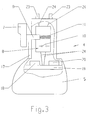
- plug contacts 23 see FIG. 3 contacted the in the handle 6 inserted energy storage 4 the electric motor 3 to the power supply.
- the power tool 1 has an actuating member 7 for actuating a switching means 8 (see FIG. 3) for the power supply of the electric motor 3.
- the actuator 7 is manually operated by the user against the force of a pressure spring 11 shown only schematically in Fig. 3 by a pressure movement, so as to turn on and off the power supply for the electric motor 3.
- both the switching means 8 and the actuator 7 in and / or the energy storage housing 5, as shown in FIG. 3 can be seen, such that no further switching means and / or actuator for switching the power supply of the electric motor. 3 is arranged on the power tool housing 2.
- the actuating member 7 acts now in its movement directly and / or indirectly actuated on the switching means 8 a.
- the switch means 8 shown schematically in FIG. 3 is a conventional electrical switch having an electromechanical contact system 10.
- the actuating member 7 acts via a plunger 9, which movably leads into the interior of the energy storage housing 5. on the switching means 8 a.
- the electromechanical contact system 10 is configured together with the actuator 7 as a self-contained, preassembled unit, so that the switching means 8 is used in the manner of a complete electrical switch in the energy storage housing 5 during assembly of the energy storage device 4.
- the switching means 8 can just as well be a sensor switch with a sensor 12, such as a force sensor, a Hall sensor, a magnetoresistive sensor, a capacitive pressure sensor or the like, as can be seen in FIG.
- the tappet 9 having actuator 7 is again against the force of a compression spring 11 movable.
- a cooperating both with the actuator 7 and the switching means 8 and / or operatively engageable transmission means 13 transmits the movement of the actuator 7 to the switching means 8.
- a transmission means 13 is a leaf spring which is attached approximately centrally to a clamping point 14. One end of the leaf spring 13 is in communication with the plunger 9, while the other end of the leaf spring 13 acts on the sensor 12 via an elastic element 15.
- the sensor 12 is mounted approximately perpendicularly projecting on a printed circuit board 19.
- the switching means 8 may be configured together with the sensor 12 and optionally the circuit board 19 and the actuator 7 as an independent, preassembled unit, which is not shown in detail.
- the actuating member 7 protrudes out of the power tool housing 2 for the user to access manually. Therefore, the actuating member 7 according to FIG. 3 or FIG. 5 also projects out of the energy storage housing 5, wherein the plunger 9 leading into the energy storage housing 5 transmits its movement to the switching means 8 on the actuating member 7.
- the energy storage 4 is inserted into the power tool housing 2 on the handle 6 by means of insertion.
- Fig. 5 in the manner of a panel on the energy storage housing 5 closes the receptacle 16 in the retracted state of the energy storage 4.
- the cover 17 is associated with the actuator 7 and arranged below the plunger 9, such that the receptacle 16 after insertion of the energy storage housing 5 is covered in the power tool housing 2 according to FIG. 2.
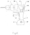
- the energy storage housing 5 itself is designed in the manner of a handle 6 'for the power tool housing 2.
- the power tool housing 2 requires no further handle, but the energy storage housing 4 takes over this function.
- the handle 6 'containing the energy store 4 can be exchangeably fastened to the part of the power tool housing 2 containing the electric motor 3.
- plug contacts 23 located in the handle 6 'energy storage 4 plug contacts 23 which can be connected to mating contacts 25 in the power tool housing 2. From the mating contacts 25 then lead leads 26 for the electrical voltage to the electric motor.
- the rotational speed of the electric motor 3 can be controlled and / or regulated, so that the rotational speed is set in accordance with the displacement of the actuating member 7, which is generated by the user by pressing the actuator 7.
- the switching means 8 is then connected to an electronics 18 schematically indicated in FIG. 3 or 5 for controlling and / or regulating the voltage supply for the electric motor 3.
- the electronics 18 may be designed in the manner of a pulse width modulation circuit, if the electric motor 3 is operated with DC voltage. In a driven with AC electric motor 3 is a phase control, phase control o. The like.
- As electronics 18. Of course, the electric motor 3 with the adjustment of the actuator 7 associated torque o. The like. By means of the electronics 18 can be operated.
- the electronics 18 is also arranged in the energy storage housing 5, namely on the circuit board 19. On the circuit board 19 can simultaneously be used for charging the energy storage 4 charging electronics 20, wherein optionally electrical and / or electrical components for both the electronics 18th as well as for the charging electronics 20 are used simultaneously. Electrical lines 24 in the energy storage housing 5 are used for electrical connection between the switching means 8 and / or the circuit board 19 with the electronics 8 and optionally the charging electronics 20 and the plug contacts 23rd
- further adjusting means for controlling and / or regulating the power supply of the electric motor 3 are still on the power tool housing. 2 arranged.
- these manually operated by the user adjustment means 27 are also arranged on the energy storage housing 5, as indicated in Fig. 6 schematically.
- the adjusting means 27 may be a potentiometer, a tap changer or the like, the adjusting means 27 serving, for example, for presetting a maximum speed, a maximum torque or the like for the operation of the electric motor 3.
- the switch assembly for a power tool 1 thus consists of the located in and / or the energy storage housing 5 actuator 7 and / or located in the energy storage housing 5 switching means 8, wherein the actuating member 7 and the switching means 8 may be configured in the manner of a preassembled unit, which in turn is inserted into the energy storage housing 5.
- the invention is not limited to the described and illustrated embodiment. Rather, it also encompasses all expert developments within the scope of the invention defined by the claims.
- the invention in particular the switch arrangement described, not only in cordless power tools but also in other electrical appliances, which are provided with a particular changeable designed energy storage, such as electrical household appliances, electrical gardening equipment, machine tools o. The like., In a variety of ways use ,
Landscapes
- Engineering & Computer Science (AREA)
- Mechanical Engineering (AREA)
- Battery Mounting, Suspending (AREA)
- Portable Power Tools In General (AREA)
- Harvester Elements (AREA)
Abstract
Description
- Die Erfindung betrifft ein Elektrowerkzeug nach dem Oberbegriff des Patentanspruchs 1.
- Bei solchen, insbesondere als Akku-Elektrowerkzeug, ausgestalteten Elektrowerkzeugen handelt es sich um Bohrmaschinen, Schraubmaschinen, Winkelschleifer, Hobel, Fräsen oder dergleichen.
- Ein solches, aus der
DE 196 04 346 A1 bekanntes Elektrowerkzeug besitzt ein Elektrowerkzeug-Gehäuse, in dem sich ein Elektromotor befindet. Zur Energieversorgung des Elektromotors dient ein Energiespeicher, und zwar ein Akku, der wiederum ein im und/oder am Elektrowerkzeug-Gehäuse wechselbar befestigbares Energiespeicher-Gehäuse aufweist. Mit Hilfe eines manuell betätigbaren Betätigungsorgans wird ein Schaltmittel für die Energieversorgung des Elektromotors, die gegebenenfalls steuer- und/oder regelbar ist, geschaltet. , - In herkömmlicher Weise ist das Schaltmittel zusammen mit dem Betätigungsorgan als Elektrowerkzeugschalter im Elektrowerkzeug-Gehäuse angeordnet, und zwar ist der Elektrowerkzeugschalter üblicherweise im Handgriff des Elektrowerkzeugs befindlich. In manchen Fällen mangelt es einer solchen Anordnung an Flexibilität. Insbesondere sind elektrische Zuleitungen vom Energiespeicher zum Elektrowerkzeugschalter und von diesem zum Elektromotor notwendig.
- Der Erfindung liegt die Aufgabe zugrunde, eine flexiblere Anordnung von Betätigungsorgan und Schaltmittel zu schaffen, insbesondere die Anordnung im Hinblick auf die Zuleitungen zu vereinfachen.
- Diese Aufgabe wird bei einem gattungsgemäßen Elektrowerkzeug durch die kennzeichnenden Merkmale des Anspruchs 1 gelöst.
- Beim erfindungsgemäßen Elektrowerkzeug sind sowohl das Schaltmittel als auch das Betätigungsorgan im und/oder am Energiespeicher-Gehäuse befindlich. Das für den Benutzer am Energiespeicher-Gehäuse manuell zugängliche Betätigungsorgan wirkt bei dessen Bewegung durch den Benutzer betätigend auf das Schaltmittel ein. Die Einwirkung des Betätigungsorgans auf das Schaltmittel kann entsprechend den Gegebenheiten im Energiespeicher-Gehäuse direkt und/oder indirekt erfolgen. Mit anderen Worten ist beim Akku-Elektrowerkzeug nach der Erfindung der Schalter mitsamt dem Betätigungsorgan in der Art eines Elektrowerkzeugschalters im Akku-Pack angeordnet ist. Vorteilhafterweise entfällt damit die bisher im Elektrowerkzeug-Gehäuse notwendige Verkabelung des Schalters mit dem Energiespeicher und dem Elektromotor, da ein wesentlicher Teil der elektrischen Leitungen im Energiespeicher-Gehäuse befindlich ist. Eine Schalteranordnung für ein solcherart ausgestaltetes Elektrowerkzeug besteht somit aus einem im und/oder am Energiespeicher-Gehäuse befindlichen Betätigungsorgan und/oder dem im Energiespeicher-Gehäuse befindlichen Schaltmittel. Weitere Ausgestaltungen der Erfindung sind Gegenstand der Unteransprüche.
- Da sowohl das Schaltmittel als auch das Betätigungsorgan im und/oder am Energiespeicher-Gehäuse befindlich sind, ist somit kein weiteres Schaltmittel und/oder Betätigungsorgan zum Schalten der Energieversorgung des Elektromotors im und/oder am Elektrowerkzeug-Gehäuse angeordnet. Allenfalls befinden sich weitere Einstellmittel für das Steuern und/oder Regeln der Energieversorgung des Elektromotors im und/oder am Elektrowerkzeug-Gehäuse. Aus Gründen der einfacheren Verkabelung ist es jedoch bevorzugt, auch diese vom Benutzer manuell bedienbaren Einstellmittel, die beispielsweise in der Art eines Potentiometers, eines Stufenschalters o. dgl. ausgestaltet sind, am und/oder im Energiespeicher-Gehäuse anzuordnen.
- Bei dem Schaltmittel kann es sich in kostengünstiger Weise um einen elektrischen Schalter handeln. Der elektrische Schalter kann weiter mit dem Betätigungsorgan als eine selbständige, vormontierbare Baueinheit ausgestaltet sein, wodurch eine einfache Montage im Energiespeicher-Gehäuse ermöglicht ist. Ebensogut kann es sich bei dem Schaltmittel auch um einen in vorteilhafter Weise verschleißfrei arbeitenden Sensorschalter, wie einen Kraftsensor, einen Hallsensor, einen magnetoresistiven Sensor o. dgl., handeln. Ein derartiger Sensorschalter gestattet darüber hinaus eine kompakte, platzsparende Anordnung im Energiespeicher-Gehäuse. Die Einwirkung des Betätigungsorgans auf das Schaltmittel kann entsprechend den Gegebenheiten im Energiespeicher-Gehäuse durch ein sowohl mit dem Betätigungsorgan als auch mit dem Schaltmittel zusammenwirkendes und/oder in Wirkverbindung bringbares Übertragungsmittel erfolgen, das die Bewegung des Betätigungsorgans beispielsweise über ein elastisches Element auf das Schaltmittel überträgt. Vorteilhafterweise läßt sich dadurch das Betätigungsorgan weitgehend ohne Restriktionen an der gewünschten Stelle im und/oder am Energiespeicher-Gehäuse anordnen, so daß die Ergonomie für den Benutzer verbessert wird. Wiederum kann das Schaltmittel mit dem Betätigungsorgan als eine selbständige, vormontierbare Baueinheit ausgestaltet sein.
- Das Betätigungsorgan ragt aus dem Energiespeicher-Gehäuse manuell zugänglich zur Bedienung durch den Benutzer heraus. Ist das Schaltmittel im Energiespeicher-Gehäuse befindlich, so überträgt in weiterer Ausgestaltung ein in das Energiespeicher-Gehäuse hineinführender Stößel am Betätigungsorgan dessen Bewegung auf das Schaltmittel. Dadurch läßt sich das Schaltmittel geschützt vor schädlichen Einflüssen, beispielsweise Staub, Feuchtigkeit o. dgl., im Energiespeicher-Gehäuse anordnen.
- Üblicherweise ist der Energiespeicher in das Elektrowerkzeug-Gehäuse an dessen Handgriff mittels Einschieben zumindest teilweise einführbar. Das Einführen des Energiespeicher-Gehäuses mit auch aus dem Elektrowerkzeug-Gehäuse herausragenden Betätigungsorgan ist dadurch ermöglicht, indem eine einseitig offene Aufnahme im Elektrowerkzeug-Gehäuse am Handgriff befindlich ist. Beim Einführen des Energiespeichers in den Handgriff läßt sich dann das Betätigungsorgan an dieser Aufnahme beziehungweise Öffnung im Handgriff durchschieben. Falls gewünscht kann eine Abdeckung in der Art einer Blende am Energiespeicher-Gehäuse, die dem Betätigungsorgan unterhalb des Stößels zugeordnet ist, angeordnet sein. Diese Blende deckt die Aufnahme nach Einführen des Energiespeicher-Gehäuses in das Elektrowerkzeug-Gehäuse ab. Im vollständig eingeschobenen Zustand des Akku-Packs ragt dann das Betätigungsorgan aus dem Handgriff am Elektrowerkzeug-Gehäuse zugänglich heraus, wobei dennoch die Öffnung entsprechend verdeckt ist.
- Alternativ kann jedoch das Energiespeicher-Gehäuse auch in der Art eines Handgriffs für das Elektrowerkzeug-Gehäuse ausgebildet sein. Folglich ist dann der Energiespeicher in den Handgriff integriert, womit in kostensparender Weise kein weiterer Handgriff für das Elektrowerkzeug-Gehäuse benötigt wird. Das als Handgriff ausgestaltete Energiespeicher-Gehäuse ist in diesem Fall an dem den Elektromotor enthaltenden Gehäuseteil des Elektrowerkzeug-Gehäuses wechselbar befestigbar.
- In bekannter Weise kann das Schaltmittel mit einer Elektronik zur Steuerung und/oder Regelung der Energieversorgung in Verbindung stehen. Diese Elektronik kann in der Art einer Pulsweitenmodulation, einer Phasenanschnittsteuerung, einer Phasenabschnittsteuerung o. dgl. arbeiten. Mit Hilfe der Elektronik wird dann der Elektromotor mit einer dem Bewegungsweg des Betätigungsorgans zugeordneten Drehzahl, einem dem Bewegungsweg des Betätigungsorgans zugeordneten Drehmoment o. dgl. betrieben. Es bietet sich nun an, die Elektronik ebenfalls im Energiespeicher-Gehäuse anzuordnen, wobei in einer besonders montagefreundlichen Ausgestaltung die Elektronik auf einer Leiterplatte im Energiespeicher-Gehäuse befindlich ist. Dadurch ist die Elektronik vor Beschädigungen im rauhen Betrieb des Elektrowerkzeugs weitgehend geschützt. Gleichzeitig kann die Elektronik zusätzlich wenigstens als Teil der Ladeelektronik zum Aufladen des Energiespeichers dienen, so daß mit einer derartigen Ausgestaltung eine zusätzliche Kosteneinsparung erzielbar ist.
- Die mit der Erfindung erzielten Vorteile bestehen insbesondere darin, daß aufgrund der Anordnung des Schaltmittels sowie des Betätigungsorgans im und/oder am Energiespeicher-Gehäuse die Flexibilität in der Gestaltung des Elektrowerkzeugs erhöht ist. Es ist folglich keine mechanisch aufwendige Trennung von Schaltmittel und Betätigungsorgan, welche fehleranfällig und auch teuer ist sowie ein zusätzliches weiteres mechanisches Übertragungsmittel zwischen Betätigungsorgan und Schaltmittel benötigt, erforderlich. Darüberhinaus wird dadurch ein kompaktes Elektrowerkzeug ermöglicht. Außerdem kann die Griffschale sehr schmal gebaut werden.
- Desweiteren kann die Ladeelektronik für den Energiespeicher im Energiespeicher-Gehäuse befindlich sein. Es bietet sich dann an, die Elektronik für die Drehzahlsteuerung und/oder
- regelung ebenfalls im Energiespeicher-Gehäuse unterzubringen, so daß das Schaltmittel in unmittelbarer Nähe der Elektronik angeordnet werden kann. Desweiteren kann die Ladeelektronik wenigstens zum Teil für die Elektronik zur Drehzahlsteuerung und/oder
- regelung mitverwendet werden, so daß hierdurch Kosteneinsparungen erzielbar sind. Da nur eine Platine für die Elektronik beziehungsweise Elektroniken notwendig ist, können weitere Kosten gespart werden.
- Außerdem wird der Verdrahtungsaufwand im Elektrowerkzeug minimiert. So ist der Elektromotor direkt mit dem Energiespeicher kontaktierbar, wodurch Zuleitungen eingespart werden sowie die Fehler- und Ausfallsicherheit gesteigert ist. Desweiteren sind Zusatzfunktionen für das Elektrowerkzeug in einfacher Weise auf der Platine implementierbar, beispielsweise kann eine Elektronik im Akkupack zur Abschaltung der Akkuspannung bei Überlastung dienen. Schließlich ist auch die Kühlung für die Elektronik auf der Platine in vielfältiger und einfacher Art und Weise möglich, beispielsweise kann sogar ein motorbetriebener Lüfter im Energiespeicher-Gehäuse angeordnet sein.
- Zusammenfassend läßt sich zum erfindungsgemäßen Elektrowerkzeug sagen, daß sich die Mittel zur manuellen Bedienung des Elektrowerkzeugs durch den Benutzer sowie auch weitgehend komplett die Elektronik im Akkupack befinden. Diese Anordnung eignet sich besonders für neue Akkutechnologien, beispielsweise für Li-Ionen- oder Li-Polymer-Technologien, bei denen eine zusätzliche Elektronik im Akkupack notwendig ist. Diese Elektronikbaugruppe im Akkupack wird erfindungsgemäß auch zur Drehzahleinstellung des Elektromotors verwendet, so daß auf die bisher übliche, in der Griffschale des Elektrowerkzeugs befindliche Elektronik für die Drehzahlverstellung verzichtet werden kann. Dadurch wird sowohl die Wirtschaftlichkeit als auch die Ergonomie gesteigert.
- Ausführungsbeispiele der Erfindung mit verschiedenen Weiterbildungen und Ausgestaltungen sind in den Zeichnungen dargestellt und werden im folgenden näher beschrieben. Es zeigen
- Fig. 1
- ein Elektrowerkzeug mit einem Energiespeicher in Seitenansicht sowie in teilweiser aufgebrochener Darstellung,
- Fig. 2
- das Elektrowerkzeug in Frontansicht entsprechend der Richtung II in Fig. 1,
- Fig. 3
- den Energiespeicher gemäß einer ersten Ausführung in Seitenansicht sowie in teilweiser aufgebrochener Darstellung,
- Fig. 4
- das Elektrowerkzeug wie Fig. 2, jedoch mit entferntem Energiespeicher,
- Fig. 5
- den Energiespeicher gemäß einer zweiten Ausführung in Seitenansicht sowie in teilweiser aufgebrochener Darstellung und
- Fig. 6
- ein Elektrowerkzeug wie in Fig. 1 entsprechend einer weiteren Ausführungsform.
- In Fig. 1 ist ein Elektrowerkzeug 1, bei dem es sich um eine Akku-Bohrmaschine handelt, gezeigt. Das Elektrowerkzeug 1 besitzt ein Elektrowerkzeug-Gehäuse 2 mit einer Werkzeugaufnahme 21 für das Werkzeug 22, beispielsweise einen Bohrer. Im Elektrowerkzeug-Gehäuse 2 befindet sich ein in Fig. 1 schematisch angedeuteter Elektromotor 3 zum Antrieb der Werkzeugaufnahme 21. Für die Energieversorgung des Elektromotors 3 dient ein Energiespeicher 4, bei dem es sich insbesondere um eine Art von Akku für die Spannungsversorgung des Elektromotors 3 handelt. Der Energiespeicher 4 weist ein Energiespeicher-Gehäuse 5 auf, das im und/oder am Elektrowerkzeug-Gehäuse 2 wechselbar befestigbar ist, und zwar durch Einstecken in den Handgriff 6 am Elektrowerkzeug-Gehäuse 2. Mittels Steckkontakten 23 (siehe Fig. 3) kontaktiert der im Handgriff 6 eingesteckte Energiespeicher 4 den Elektromotor 3 zu dessen Spannungsversorgung.
- Das Elektrowerkzeug 1 weist ein Betätigungsorgan 7 zum Betätigen eines Schaltmittels 8 (siehe Fig. 3) für die Energieversorgung des Elektromotors 3 auf. Das Betätigungsorgan 7 ist vom Benutzer gegen die Kraft einer in Fig. 3 lediglich schematisch gezeigten Druckfeder 11 durch eine Druckbewegung manuell betätigbar, um so die Spannungsversorgung für den Elektromotor 3 ein- und/oder auszuschalten. Entgegen der bisherigen Anordnung befinden sich sowohl das Schaltmittel 8 als auch das Betätigungsorgan 7 im und/oder am Energiespeicher-Gehäuse 5, wie anhand der Fig. 3 ersichtlich ist, derart daß kein weiteres Schaltmittel und/oder Betätigungsorgan zum Schalten der Energieversorgung des Elektromotors 3 am Elektrowerkzeug-Gehäuse 2 angeordnet ist. Das Betätigungsorgan 7 wirkt nun bei dessen Bewegung direkt und/oder indirekt betätigend auf das Schaltmittel 8 ein.
- Bei dem in Fig. 3 schematisch angedeuteten Schaltmittel 8 handelt es sich um einen in herkömmlicher Art und Weise ausgebildeten elektrischen Schalter mit einem elektromechanischen Kontaktsystem 10. Das Betätigungsorgan 7 wirkt über einen Stößel 9, der beweglich in das Innere des Energiespeicher-Gehäuses 5 hineinführt, auf das Schaltmittel 8 ein. Das elektromechanische Kontaktsystem 10 ist zusammen mit dem Betätigungsorgan 7 als eine selbständige, vormontierbare Baueinheit ausgestaltet, so daß das Schaltmittel 8 in der Art eines kompletten elektrischen Schalters in das Energiespeicher-Gehäuse 5 bei Montage des Energiespeichers 4 eingesetzt wird.
- Ebensogut kann es sich bei dem Schaltmittel 8 um einen Sensorschalter mit einem Sensor 12, wie einen Kraftsensor, einen Hallsensor, einen magnetoresistiven Sensor, einen kapazitiven Drucksensor o. dgl., handeln, wie in Fig. 5 zu sehen ist. Das einen Stößel 9 aufweisende Betätigungsorgan 7 ist wiederum gegen die Kraft einer Druckfeder 11 bewegbar. Ein sowohl mit dem Betätigungsorgan 7 als auch mit dem Schaltmittel 8 zusammenwirkendes und/oder in Wirkverbindung bringbares Übertragungsmittel 13 überträgt die Bewegung des Betätigungsorgans 7 auf das Schaltmittel 8. Als Übertragungsmittel 13 dient eine Blattfeder, die in etwa mittig an einer Einspannstelle 14 befestigt ist. Ein Ende der Blattfeder 13 steht mit dem Stößel 9 in Verbindung, während das andere Ende der Blattfeder 13 über ein elastisches Element 15 auf den Sensor 12 einwirkt.
- Der Sensor 12 ist in etwa senkrecht abstehend auf einer Leiterplatte 19 angebracht. Auch hier kann das Schaltmittel 8 mitsamt dem Sensor 12 und gegebenenfalls der Leiterplatte 19 sowie mit dem Betätigungsorgan 7 als eine selbständige, vormontierbare Baueinheit ausgestaltet sein, was jedoch nicht näher gezeigt ist.
- Wie anhand von Fig. 1 zu erkennen ist, ragt das Betätigungsorgan 7 aus dem Elektrowerkzeug-Gehäuse 2 für den Benutzer manuell zugänglich heraus. Daher ragt das Betätigungsorgan 7 gemäß Fig. 3 oder Fig. 5 auch aus dem Energiespeicher-Gehäuse 5 heraus, wobei der in das Energiespeicher-Gehäuse 5 hineinführende Stößel 9 am Betätigungsorgan 7 dessen Bewegung auf das Schaltmittel 8 überträgt. Der Energiespeicher 4 ist in das Elektrowerkzeug-Gehäuse 2 an dessen Handgriff 6 mittels Einschieben einführbar. Um das Einschieben mitsamt dem aus dem Elektrowerkzeug-Gehäuse 2 herausragenden Betätigungsorgan 7 zu gestatten, befindet sich eine einseitig offene Aufnahme 16 im Handgriff 6 des Elektrowerkzeug-Gehäuses 2, wie man anhand von Fig. 4 sieht, derart daß der Stößel 9 in der Aufnahme 16 durchschiebbar ist. Eine in Fig. 3 oder Fig. 5 gezeigte Abdeckung 17 in der Art einer Blende am Energiespeicher-Gehäuse 5 schließt die Aufnahme 16 im eingeschobenen Zustand des Energiespeichers 4. Die Abdeckung 17 ist dem Betätigungsorgan 7 zugeordnet sowie unterhalb des Stößels 9 angeordnet, derart daß die Aufnahme 16 nach Einführen des Energiespeicher-Gehäuses 5 in das Elektrowerkzeug-Gehäuse 2 entsprechend der Fig. 2 abgedeckt ist.
- Gemäß einer weiteren Ausführungsform, die in Fig. 6 gezeigt ist, ist das Energiespeicher-Gehäuse 5 selbst in der Art eines Handgriffs 6' für das Elektrowerkzeug-Gehäuse 2 ausgebildet. Dadurch benötigt das Elektrowerkzeug-Gehäuse 2 keinen weiteren Handgriff, vielmehr übernimmt das Energiespeicher-Gehäuse 4 diese Funktion. Wie man weiter der Fig. 6 entnimmt, ist der den Energiespeicher 4 beinhaltende Handgriff 6' an dem den Elektromotor 3 enthaltenden Teil des Elektrowerkzeug-Gehäuses 2 wechselbar befestigbar. Dazu weist der im Handgriff 6' befindliche Energiespeicher 4 Steckkontakte 23 auf, die an Gegenkontakten 25 im Elektrowerkzeug-Gehäuse 2 ansteckbar sind. Von den Gegenkontakten 25 führen dann Zuleitungen 26 für die elektrische Spannung zum Elektromotor 3.
- Falls gewünscht kann die Drehzahl des Elektromotors 3 steuer- und/oder regelbar sein, so daß die Drehzahl entsprechend dem Verstellweg des Betätigungsorgans 7, der vom Benutzer durch Drücken am Betätigungsorgan 7 erzeugt wird, eingestellt wird. Das Schaltmittel 8 steht dann mit einer in Fig. 3 oder Fig. 5 schematisch angedeuteten Elektronik 18 zur Steuerung und/oder Regelung der Spannungsversorgung für den Elektromotor 3 in Verbindung. Die Elektronik 18 kann in der Art einer Pulsweitenmodulation-Schaltung ausgestaltet sein, falls der Elektromotor 3 mit Gleichspannung betrieben wird. Bei einem mit Wechselspannung betriebenen Elektromotor 3 eignet sich eine Phasenanschnittsteuerung, eine Phasenabschnittsteuerung o. dgl. als Elektronik 18. Selbstverständlich kann der Elektromotor 3 auch mit einem dem Verstellweg des Betätigungsorgans 7 zugeordneten Drehmoment o. dgl. mittels der Elektronik 18 betreibbar sein. Die Elektronik 18 ist ebenfalls im Energiespeicher-Gehäuse 5 angeordnet, und zwar auf der Leiterplatte 19. Auf der Leiterplatte 19 kann gleichzeitig die zum Aufladen des Energiespeichers 4 dienende Ladeelektronik 20 befindlich sein, wobei gegebenenfalls elektrische und/oder elektrische Bauteile sowohl für die Elektronik 18 als auch für die Ladeelektronik 20 gleichzeitig verwendbar sind. Elektrische Leitungen 24 im Energiespeicher-Gehäuse 5 dienen zur elektrischen Verbindung zwischen dem Schaltmittel 8 und/oder der Leiterplatte 19 mit der Elektronik 8 und gegebenenfalls der Ladeelektronik 20 sowie den Steckkontakten 23.
- Wie bereits ausgeführt, befindet sich das Schaltmittel 8 und/oder das Betätigungsorgan 7 zum Schalten der Energieversorgung des Elektromotors 3 am Elektrowerkzeug-Gehäuse 2. Allenfalls weitere Einstellmittel für das Steuern und/oder Regeln der Energieversorgung des Elektromotors 3 sind noch am Elektrowerkzeug-Gehäuse 2 angeordnet. Zweckmäßigerweise sind jedoch auch diese vom Benutzer manuell bedienbare Einstellmittel 27 ebenfalls am Energiespeicher-Gehäuse 5 angeordnet, wie in Fig. 6 schematisch angedeutet. Bei dem Einstellmittel 27 kann es sich um ein Potentiometer, einen Stufenschalter o. dgl. handeln, wobei das Einstellmittel 27 beispielsweise zur Voreinstellung einer maximalen Drehzahl, eines maximalen Drehmoments o. dgl. für den Betrieb des Elektromotors 3 dient.
- Die Schalteranordnung für ein Elektrowerkzeug 1 gemäß der vorstehenden Beschreibung besteht somit aus dem im und/oder am Energiespeicher-Gehäuse 5 befindlichen Betätigungsorgan 7 und/oder dem im Energiespeicher-Gehäuse 5 befindlichen Schaltmittel 8, wobei das Betätigungsorgan 7 sowie das Schaltmittel 8 in der Art einer vormontierten Baueinheit ausgestaltet sein können, die wiederum in das Energiespeicher-Gehäuse 5 eingesetzt wird. Die Erfindung ist jedoch nicht auf das beschriebene und dargestellte Ausführungsbeispiel beschränkt. Sie umfaßt vielmehr auch alle fachmännischen Weiterbildungen im Rahmen der durch die Patentansprüche definierten Erfindung. So kann die Erfindung, insbesondere die beschriebene Schalteranordnung, nicht nur bei Akku-Elektrowerkzeugen sondern auch bei sonstigen Elektrogeräten, die mit einem insbesondere wechselbar ausgestalteten Energiespeicher versehen sind, wie Elektrohaushaltsgeräten, Elektrogartengeräten, Werkzeugmaschinen o. dgl., in vielfältiger Art und Weise Verwendung finden.
-
- 1:
- Elektrowerkzeug
- 2:
- Elektrowerkzeug-Gehäuse
- 3:
- Elektromotor
- 4:
- Energiespeicher
- 5:
- Energiespeicher-Gehäuse
- 6, 6':
- Handgriff
- 7:
- Betätigungsorgan
- 8:
- Schaltmittel
- 9:
- Stößel
- 10:
- elektrischer Schalter / elektromechanisches Kontaktsystem
- 11:
- Druckfeder
- 12:
- Sensorschalter / Sensor
- 13:
- Übertragungsmittel / Blattfeder
- 14:
- Einspannstelle
- 15:
- elastisches Element
- 16:
- Aufnahme
- 17:
- Abdeckung
- 18:
- Elektronik (für die Drehzahl)
- 19:
- Leiterplatte
- 20:
- Ladeelektronik
- 21:
- Werkzeugaufnahme
- 22:
- Werkzeug
- 23:
- Steckkontakt
- 24:
- elektrische Leitung
- 25:
- Gegenkontakt
- 26:
- Zuleitung
- 27:
- Einstellmittel
Claims (9)
- Elektrowerkzeug, insbesondere Akku-Elektrowerkzeug, mit einem Elektrowerkzeug-Gehäuse (2), mit einem im Elektrowerkzeug-Gehäuse (2) befindlichen Elektromotor (3), mit einem Energiespeicher (4), insbesondere in der Art eines Akkus, für die Energieversorgung des Elektromotors (3), sowie mit einem mittels eines Betätigungsorgans (7) betätigbaren Schaltmittel (8) zum Schalten, Steuern, Regeln o. dgl. der Energieversorgung des Elektromotors (3), wobei der Energiespeicher (4) ein Energiespeicher-Gehäuse (5) aufweist, und wobei das Energiespeicher-Gehäuse (5) im und/oder am Elektrowerkzeug-Gehäuse (2) befestigbar ist, dadurch gekennzeichnet, daß sowohl das Schaltmittel (8) als auch das Betätigungsorgan (7) im und/oder am Energiespeicher-Gehäuse (5) befindlich sind, und daß das Betätigungsorgan (7) bei dessen Bewegung, insbesondere direkt und/oder indirekt, betätigend auf das Schaltmittel (8) einwirkt.
- Elektrowerkzeug nach Anspruch 1, dadurch gekennzeichnet, daß es sich bei dem Schaltmittel (8) um einen elektrischen Schalter mit einem elektromechanischen Kontaktsystem (10) handelt, und daß vorzugsweise der elektrische Schalter (10) mit dem Betätigungsorgan (7) als eine Baueinheit ausgestaltet ist.
- Elektrowerkzeug nach Anspruch 1, dadurch gekennzeichnet, daß es sich bei dem Schaltmittel (8) um einen Sensorschalter mit einem Sensor (12), wie einen Kraftsensor, einen Hallsensor, einen magnetoresistiven Sensor o. dgl., handelt, daß vorzugsweise ein sowohl mit dem Betätigungsorgan (7) als auch mit dem Schaltmittel (8) zusammenwirkendes und/oder in Wirkverbindung bringbares Übertragungsmittel (13) die Bewegung des Betätigungsorgans (7) auf das Schaltmittel (8) überträgt, daß weiter vorzugsweise das Übertragungsmittel (13) über ein elastisches Element (15) auf den Sensorschalter (12) einwirkt, und daß noch weiter vorzugsweise der Sensorschalter (12) mit dem Betätigungsorgan (7) als eine Baueinheit ausgestaltet ist.
- Elektrowerkzeug nach Anspruch 1, 2 oder 3, dadurch gekennzeichnet, daß das Betätigungsorgan (7) aus dem Energiespeicher-Gehäuse (5) manuell zugänglich herausragt, und daß vorzugsweise ein Stößel (9) am Betätigungsorgan (7) dessen Bewegung auf das Schaltmittel (8) überträgt.
- Elektrowerkzeug nach einem der Ansprüche 1 bis 4, dadurch gekennzeichnet, daß das Energiespeicher-Gehäuse (5) in das Elektrowerkzeug-Gehäuse (2), insbesondere an dessen Handgriff (6), einführbar ist, daß vorzugsweise eine insbesondere einseitig offene Aufnahme (16) im Elektrowerkzeug-Gehäuse (2) befindlich ist, derart daß das Einführen des Energiespeicher-Gehäuses (5) mit aus dem Elektrowerkzeug-Gehäuse (2) herausragenden Betätigungsorgan (7) ermöglicht ist, und daß weiter vorzugsweise eine Abdeckung (17) in der Art einer Blende am Energiespeicher-Gehäuse (5), insbesondere dem Betätigungsorgan (7) zugeordnet sowie bevorzugterweise unterhalb des Stößels (9) angeordnet ist, derart daß die Aufnahme (16) nach Einführen des Energiespeicher-Gehäuses (5) in das Elektrowerkzeug-Gehäuse (2) abgedeckt ist.
- Elektrowerkzeug nach einem der Ansprüche 1 bis 4, dadurch gekennzeichnet, daß das Energiespeicher-Gehäuse (5) in der Art eines Handgriffs (6') für das Elektrowerkzeug-Gehäuse (2) ausgebildet ist, derart daß der den Energiespeicher (4) beinhaltende Handgriff (6') am Elektrowerkzeug-Gehäuse (2) befestigbar ist.
- Elektrowerkzeug nach einem der Ansprüche 1 bis 6, dadurch gekennzeichnet, daß das Schaltmittel (8) mit einer Elektronik (18) zur Steuerung und/oder Regelung der Energieversorgung, insbesondere in der Art einer Pulsweitenmodulation, einer Phasenanschnittsteuerung, einer Phasenabschnittsteuerung o. dgl., in Verbindung steht, und zwar bevorzugterweise derart daß der Elektromotor (3) mit einer dem Bewegungsweg des Betätigungsorgans (7) zugeordneten Drehzahl, einem dem Bewegungsweg des Betätigungsorgans (7) zugeordneten Drehmoment o. dgl. betreibbar ist, daß vorzugsweise die Elektronik (18) im Energiespeicher-Gehäuse (5) angeordnet ist, daß weiter vorzugsweise die Elektronik (18) zusätzlich wenigstens als Teil der Ladeelektronik (20) zum Aufladen des Energiespeichers (4) dient, und daß noch weiter vorzugsweise die Elektronik (18) und/oder die Ladeelektronik (20) auf einer Leiterplatte (19) im Energiespeicher-Gehäuse (5) befindlich ist.
- Elektrowerkzeug nach einem der Ansprüche 1 bis 7, dadurch gekennzeichnet, daß ein Einstellmittel (27) für das Steuern und/oder Regeln der Energieversorgung des Elektromotors (3), insbesondere in der Art eines Potentiometers, eines Stufenschalters o. dgl., am und/oder im Energiespeicher-Gehäuse (5) angeordnet ist.
- Schalteranordnung bestehend aus einem im und/oder am Energiespeicher-Gehäuse (5) befindlichen Betätigungsorgan (7) und/oder Schaltmittel (8) für ein Elektrowerkzeug (1) nach einem der vorstehenden Ansprüche.
Applications Claiming Priority (1)
| Application Number | Priority Date | Filing Date | Title |
|---|---|---|---|
| DE102005054498 | 2005-11-16 |
Publications (2)
| Publication Number | Publication Date |
|---|---|
| EP1788597A1 true EP1788597A1 (de) | 2007-05-23 |
| EP1788597B1 EP1788597B1 (de) | 2008-12-31 |
Family
ID=37758652
Family Applications (1)
| Application Number | Title | Priority Date | Filing Date |
|---|---|---|---|
| EP06023399A Not-in-force EP1788597B1 (de) | 2005-11-16 | 2006-11-10 | Elektrowerkzeug, insbesondere Akku-Elektrowerkzeug |
Country Status (3)
| Country | Link |
|---|---|
| EP (1) | EP1788597B1 (de) |
| AT (1) | ATE419636T1 (de) |
| DE (1) | DE502006002480D1 (de) |
Cited By (4)
| Publication number | Priority date | Publication date | Assignee | Title |
|---|---|---|---|---|
| EP2008776A1 (de) * | 2007-06-27 | 2008-12-31 | Marquardt GmbH | Elektrowerkzeug, insbesondere Akku-Elektrowerkzeug |
| WO2014039868A3 (en) * | 2012-09-07 | 2014-05-01 | Robert Bosch Gmbh | Slide switch for a power tool |
| US20150182230A1 (en) * | 2012-05-23 | 2015-07-02 | Stryker Corporation | Battery and control module for both energizing and controlling a powered surgical tool that is releasably attached to the module |
| ITUB20160783A1 (it) * | 2016-02-16 | 2017-08-16 | Tech4Sea Srl | Sistema di attuazione per utensili elettrici |
Families Citing this family (3)
| Publication number | Priority date | Publication date | Assignee | Title |
|---|---|---|---|---|
| CN108927855A (zh) * | 2018-08-01 | 2018-12-04 | 苏州穹力机械科技有限公司 | 手动开孔机 |
| WO2020231974A1 (en) | 2019-05-13 | 2020-11-19 | Milwaukee Electric Tool Corporation | Contactless trigger with rotational magnetic sensor for a power tool |
| CN114868513A (zh) | 2021-02-05 | 2022-08-09 | 米沃奇电动工具公司 | 用于割草机的非接触开关 |
Citations (8)
| Publication number | Priority date | Publication date | Assignee | Title |
|---|---|---|---|---|
| US3973179A (en) * | 1974-08-23 | 1976-08-03 | The Black And Decker Manufacturing Company | Modular cordless tools |
| GB1515390A (en) * | 1974-08-23 | 1978-06-21 | Black & Decker Mfg Co | Battery-operated electrical appliance of modular construction |
| EP0726586A2 (de) * | 1995-02-10 | 1996-08-14 | Marquardt GmbH | Elektrischer Schalter, insbesondere Schalter für Akku-Elektrowerkzeuge |
| DE19913712A1 (de) * | 1998-04-04 | 1999-10-07 | Marquardt Gmbh | Elektrischer Schalter |
| EP1075906A2 (de) * | 1999-07-14 | 2001-02-14 | Black & Decker Inc. | Lösbare Verbindung zwischen Batteriemodulen und elektrischen Geräten |
| US20030089511A1 (en) * | 2001-11-12 | 2003-05-15 | Yukio Tsuneda | Electric tool |
| DE10246761A1 (de) * | 2002-10-07 | 2004-04-15 | Hilti Ag | Batteriebetriebene Elektrohandwerkzeugmaschine |
| EP1439037A2 (de) * | 2002-12-19 | 2004-07-21 | HILTI Aktiengesellschaft | Elektrohandwerkzeugmaschine mit kontaktlosem elektrischen Handschalter |
-
2006
- 2006-11-10 AT AT06023399T patent/ATE419636T1/de not_active IP Right Cessation
- 2006-11-10 DE DE502006002480T patent/DE502006002480D1/de active Active
- 2006-11-10 EP EP06023399A patent/EP1788597B1/de not_active Not-in-force
Patent Citations (8)
| Publication number | Priority date | Publication date | Assignee | Title |
|---|---|---|---|---|
| US3973179A (en) * | 1974-08-23 | 1976-08-03 | The Black And Decker Manufacturing Company | Modular cordless tools |
| GB1515390A (en) * | 1974-08-23 | 1978-06-21 | Black & Decker Mfg Co | Battery-operated electrical appliance of modular construction |
| EP0726586A2 (de) * | 1995-02-10 | 1996-08-14 | Marquardt GmbH | Elektrischer Schalter, insbesondere Schalter für Akku-Elektrowerkzeuge |
| DE19913712A1 (de) * | 1998-04-04 | 1999-10-07 | Marquardt Gmbh | Elektrischer Schalter |
| EP1075906A2 (de) * | 1999-07-14 | 2001-02-14 | Black & Decker Inc. | Lösbare Verbindung zwischen Batteriemodulen und elektrischen Geräten |
| US20030089511A1 (en) * | 2001-11-12 | 2003-05-15 | Yukio Tsuneda | Electric tool |
| DE10246761A1 (de) * | 2002-10-07 | 2004-04-15 | Hilti Ag | Batteriebetriebene Elektrohandwerkzeugmaschine |
| EP1439037A2 (de) * | 2002-12-19 | 2004-07-21 | HILTI Aktiengesellschaft | Elektrohandwerkzeugmaschine mit kontaktlosem elektrischen Handschalter |
Cited By (13)
| Publication number | Priority date | Publication date | Assignee | Title |
|---|---|---|---|---|
| EP2008776A1 (de) * | 2007-06-27 | 2008-12-31 | Marquardt GmbH | Elektrowerkzeug, insbesondere Akku-Elektrowerkzeug |
| US20210369285A1 (en) * | 2012-05-23 | 2021-12-02 | Stryker Corporation | Surgical Tool System With Interchangeable Battery and Control Modules |
| US20150182230A1 (en) * | 2012-05-23 | 2015-07-02 | Stryker Corporation | Battery and control module for both energizing and controlling a powered surgical tool that is releasably attached to the module |
| CN107496003A (zh) * | 2012-05-23 | 2017-12-22 | 史赛克公司 | 具有重叠手术工具单元的可再充电位置的、用于手术工具单元的电池和控制模块 |
| US10076340B2 (en) * | 2012-05-23 | 2018-09-18 | Stryker Corporation | Surgical tool system with a tool unit that includes a power generating unit and a battery and control module that is releasably attached to the tool unit for energizing and controlling the power generating unit |
| CN107496003B (zh) * | 2012-05-23 | 2021-02-09 | 史赛克公司 | 具有重叠手术工具单元的可再充电位置的、用于手术工具单元的电池和控制模块 |
| US11103254B2 (en) | 2012-05-23 | 2021-08-31 | Stryker Corporation | Surgical tool system with a battery and control module having a driver capable of reusing contacts |
| US12029439B2 (en) * | 2012-05-23 | 2024-07-09 | Stryker Corporation | Surgical tool system with interchangeable battery and control modules |
| US20240325031A1 (en) * | 2012-05-23 | 2024-10-03 | Stryker Corporation | Surgical Tool System Including a Bore for Receiving Wire |
| US20250160852A1 (en) * | 2012-05-23 | 2025-05-22 | Stryker Corporation | Surgical Tool System Including Semi-Flexible Contact Pin Mounts |
| US9242362B2 (en) | 2012-09-07 | 2016-01-26 | Robert Bosch Gmbh | Slide switch for a power tool |
| WO2014039868A3 (en) * | 2012-09-07 | 2014-05-01 | Robert Bosch Gmbh | Slide switch for a power tool |
| ITUB20160783A1 (it) * | 2016-02-16 | 2017-08-16 | Tech4Sea Srl | Sistema di attuazione per utensili elettrici |
Also Published As
| Publication number | Publication date |
|---|---|
| ATE419636T1 (de) | 2009-01-15 |
| EP1788597B1 (de) | 2008-12-31 |
| DE502006002480D1 (de) | 2009-02-12 |
Similar Documents
| Publication | Publication Date | Title |
|---|---|---|
| EP1765557B1 (de) | Elektrowerkzeug, insbesondere akku-elektrowerkzeug | |
| EP0182986B1 (de) | Kraftgetriebene Schraubvorrichtung mit variabler Drehmomenteinstellung | |
| EP2008776B1 (de) | Elektrowerkzeug, insbesondere Akku-Elektrowerkzeug | |
| EP1895555A2 (de) | Handwerkzeugmaschine | |
| DE102009027705A1 (de) | Handgeführtes Elektrowerkzeug | |
| DE102014217863A1 (de) | Handwerkzeugmaschine | |
| DE102010004967A1 (de) | Elektrischer Schalter | |
| EP1788597B1 (de) | Elektrowerkzeug, insbesondere Akku-Elektrowerkzeug | |
| DE112017006677T5 (de) | Schraubendreher | |
| DE102004003711A1 (de) | Elektrische Handwerkzeugmaschine, die einen insbesondere elektronisch kommutierten Elektromotor aufweist | |
| EP3822035A1 (de) | Handgriffvorrichtung für eine werkzeugmaschine | |
| DE102006052366A1 (de) | Elektrowerkzeug, insbesondere Akku-Elektrowerkzeug | |
| DE102009009965A1 (de) | Elektrischer Schalter, insbesondere Elektrowerkzeugschalter | |
| EP2406801B1 (de) | Elektrischer schalter | |
| DE3324545A1 (de) | Elektromotorisch betriebenes handgeraet | |
| DE102010034377A1 (de) | Elektrischer Schalter | |
| WO2009065390A1 (de) | Elektrohandwerkzeug | |
| EP2561532B1 (de) | Elektrischer schalter | |
| EP2162979B1 (de) | Ansteuereinrichtung für einen elektromotor | |
| DE102005035046B4 (de) | Elektrowerkzeug | |
| EP1472708B1 (de) | Elektrische schaltanordnung für ein elektrowerkzeug | |
| DE102007031016A1 (de) | Elektrischer Schalter | |
| EP2195917B1 (de) | Schaltungsanordnung für ein elektrowerkzeug | |
| EP0085730B1 (de) | Zweipoliger Druckschalter mit elektronischer Steuer- und Regeleinrichtung zum Einbau in von Hand benutzte Elektrogeräte | |
| DE102005032608A1 (de) | Elektrowerkzeug, insbesondere Akku-Elektrowerkzeug |
Legal Events
| Date | Code | Title | Description |
|---|---|---|---|
| PUAI | Public reference made under article 153(3) epc to a published international application that has entered the european phase |
Free format text: ORIGINAL CODE: 0009012 |
|
| AK | Designated contracting states |
Kind code of ref document: A1 Designated state(s): AT BE BG CH CY CZ DE DK EE ES FI FR GB GR HU IE IS IT LI LT LU LV MC NL PL PT RO SE SI SK TR |
|
| AX | Request for extension of the european patent |
Extension state: AL BA HR MK YU |
|
| 17P | Request for examination filed |
Effective date: 20070817 |
|
| 17Q | First examination report despatched |
Effective date: 20070920 |
|
| AKX | Designation fees paid |
Designated state(s): AT BE BG CH CY CZ DE DK EE ES FI FR GB GR HU IE IS IT LI LT LU LV MC NL PL PT RO SE SI SK TR |
|
| GRAP | Despatch of communication of intention to grant a patent |
Free format text: ORIGINAL CODE: EPIDOSNIGR1 |
|
| GRAS | Grant fee paid |
Free format text: ORIGINAL CODE: EPIDOSNIGR3 |
|
| GRAA | (expected) grant |
Free format text: ORIGINAL CODE: 0009210 |
|
| AK | Designated contracting states |
Kind code of ref document: B1 Designated state(s): AT BE BG CH CY CZ DE DK EE ES FI FR GB GR HU IE IS IT LI LT LU LV MC NL PL PT RO SE SI SK TR |
|
| REG | Reference to a national code |
Ref country code: CH Ref legal event code: EP Ref country code: GB Ref legal event code: FG4D Free format text: NOT ENGLISH |
|
| REF | Corresponds to: |
Ref document number: 502006002480 Country of ref document: DE Date of ref document: 20090212 Kind code of ref document: P |
|
| REG | Reference to a national code |
Ref country code: IE Ref legal event code: FG4D Free format text: LANGUAGE OF EP DOCUMENT: GERMAN |
|
| REG | Reference to a national code |
Ref country code: CH Ref legal event code: NV Representative=s name: KELLER & PARTNER PATENTANWAELTE AG |
|
| PG25 | Lapsed in a contracting state [announced via postgrant information from national office to epo] |
Ref country code: SI Free format text: LAPSE BECAUSE OF FAILURE TO SUBMIT A TRANSLATION OF THE DESCRIPTION OR TO PAY THE FEE WITHIN THE PRESCRIBED TIME-LIMIT Effective date: 20081231 Ref country code: PL Free format text: LAPSE BECAUSE OF FAILURE TO SUBMIT A TRANSLATION OF THE DESCRIPTION OR TO PAY THE FEE WITHIN THE PRESCRIBED TIME-LIMIT Effective date: 20081231 Ref country code: FI Free format text: LAPSE BECAUSE OF FAILURE TO SUBMIT A TRANSLATION OF THE DESCRIPTION OR TO PAY THE FEE WITHIN THE PRESCRIBED TIME-LIMIT Effective date: 20081231 Ref country code: LV Free format text: LAPSE BECAUSE OF FAILURE TO SUBMIT A TRANSLATION OF THE DESCRIPTION OR TO PAY THE FEE WITHIN THE PRESCRIBED TIME-LIMIT Effective date: 20081231 |
|
| PG25 | Lapsed in a contracting state [announced via postgrant information from national office to epo] |
Ref country code: LT Free format text: LAPSE BECAUSE OF FAILURE TO SUBMIT A TRANSLATION OF THE DESCRIPTION OR TO PAY THE FEE WITHIN THE PRESCRIBED TIME-LIMIT Effective date: 20081231 Ref country code: EE Free format text: LAPSE BECAUSE OF FAILURE TO SUBMIT A TRANSLATION OF THE DESCRIPTION OR TO PAY THE FEE WITHIN THE PRESCRIBED TIME-LIMIT Effective date: 20081231 Ref country code: RO Free format text: LAPSE BECAUSE OF FAILURE TO SUBMIT A TRANSLATION OF THE DESCRIPTION OR TO PAY THE FEE WITHIN THE PRESCRIBED TIME-LIMIT Effective date: 20081231 Ref country code: ES Free format text: LAPSE BECAUSE OF FAILURE TO SUBMIT A TRANSLATION OF THE DESCRIPTION OR TO PAY THE FEE WITHIN THE PRESCRIBED TIME-LIMIT Effective date: 20090411 |
|
| REG | Reference to a national code |
Ref country code: IE Ref legal event code: FD4D |
|
| PG25 | Lapsed in a contracting state [announced via postgrant information from national office to epo] |
Ref country code: IS Free format text: LAPSE BECAUSE OF FAILURE TO SUBMIT A TRANSLATION OF THE DESCRIPTION OR TO PAY THE FEE WITHIN THE PRESCRIBED TIME-LIMIT Effective date: 20090430 Ref country code: SE Free format text: LAPSE BECAUSE OF FAILURE TO SUBMIT A TRANSLATION OF THE DESCRIPTION OR TO PAY THE FEE WITHIN THE PRESCRIBED TIME-LIMIT Effective date: 20090331 Ref country code: CZ Free format text: LAPSE BECAUSE OF FAILURE TO SUBMIT A TRANSLATION OF THE DESCRIPTION OR TO PAY THE FEE WITHIN THE PRESCRIBED TIME-LIMIT Effective date: 20081231 Ref country code: PT Free format text: LAPSE BECAUSE OF FAILURE TO SUBMIT A TRANSLATION OF THE DESCRIPTION OR TO PAY THE FEE WITHIN THE PRESCRIBED TIME-LIMIT Effective date: 20090601 |
|
| PG25 | Lapsed in a contracting state [announced via postgrant information from national office to epo] |
Ref country code: SK Free format text: LAPSE BECAUSE OF FAILURE TO SUBMIT A TRANSLATION OF THE DESCRIPTION OR TO PAY THE FEE WITHIN THE PRESCRIBED TIME-LIMIT Effective date: 20081231 |
|
| PG25 | Lapsed in a contracting state [announced via postgrant information from national office to epo] |
Ref country code: IE Free format text: LAPSE BECAUSE OF FAILURE TO SUBMIT A TRANSLATION OF THE DESCRIPTION OR TO PAY THE FEE WITHIN THE PRESCRIBED TIME-LIMIT Effective date: 20081231 Ref country code: DK Free format text: LAPSE BECAUSE OF FAILURE TO SUBMIT A TRANSLATION OF THE DESCRIPTION OR TO PAY THE FEE WITHIN THE PRESCRIBED TIME-LIMIT Effective date: 20081231 |
|
| PLBE | No opposition filed within time limit |
Free format text: ORIGINAL CODE: 0009261 |
|
| STAA | Information on the status of an ep patent application or granted ep patent |
Free format text: STATUS: NO OPPOSITION FILED WITHIN TIME LIMIT |
|
| 26N | No opposition filed |
Effective date: 20091001 |
|
| PG25 | Lapsed in a contracting state [announced via postgrant information from national office to epo] |
Ref country code: BG Free format text: LAPSE BECAUSE OF FAILURE TO SUBMIT A TRANSLATION OF THE DESCRIPTION OR TO PAY THE FEE WITHIN THE PRESCRIBED TIME-LIMIT Effective date: 20090331 |
|
| BERE | Be: lapsed |
Owner name: MARQUARDT G.M.B.H. Effective date: 20091130 |
|
| PG25 | Lapsed in a contracting state [announced via postgrant information from national office to epo] |
Ref country code: MC Free format text: LAPSE BECAUSE OF NON-PAYMENT OF DUE FEES Effective date: 20091130 |
|
| REG | Reference to a national code |
Ref country code: FR Ref legal event code: ST Effective date: 20100730 |
|
| PG25 | Lapsed in a contracting state [announced via postgrant information from national office to epo] |
Ref country code: BE Free format text: LAPSE BECAUSE OF NON-PAYMENT OF DUE FEES Effective date: 20091130 Ref country code: GR Free format text: LAPSE BECAUSE OF FAILURE TO SUBMIT A TRANSLATION OF THE DESCRIPTION OR TO PAY THE FEE WITHIN THE PRESCRIBED TIME-LIMIT Effective date: 20090401 Ref country code: FR Free format text: LAPSE BECAUSE OF NON-PAYMENT OF DUE FEES Effective date: 20091130 |
|
| PG25 | Lapsed in a contracting state [announced via postgrant information from national office to epo] |
Ref country code: AT Free format text: LAPSE BECAUSE OF NON-PAYMENT OF DUE FEES Effective date: 20091110 |
|
| PG25 | Lapsed in a contracting state [announced via postgrant information from national office to epo] |
Ref country code: IT Free format text: LAPSE BECAUSE OF FAILURE TO SUBMIT A TRANSLATION OF THE DESCRIPTION OR TO PAY THE FEE WITHIN THE PRESCRIBED TIME-LIMIT Effective date: 20081231 |
|
| PG25 | Lapsed in a contracting state [announced via postgrant information from national office to epo] |
Ref country code: LU Free format text: LAPSE BECAUSE OF NON-PAYMENT OF DUE FEES Effective date: 20091110 |
|
| PG25 | Lapsed in a contracting state [announced via postgrant information from national office to epo] |
Ref country code: HU Free format text: LAPSE BECAUSE OF FAILURE TO SUBMIT A TRANSLATION OF THE DESCRIPTION OR TO PAY THE FEE WITHIN THE PRESCRIBED TIME-LIMIT Effective date: 20090701 |
|
| GBPC | Gb: european patent ceased through non-payment of renewal fee |
Effective date: 20101110 |
|
| PG25 | Lapsed in a contracting state [announced via postgrant information from national office to epo] |
Ref country code: TR Free format text: LAPSE BECAUSE OF FAILURE TO SUBMIT A TRANSLATION OF THE DESCRIPTION OR TO PAY THE FEE WITHIN THE PRESCRIBED TIME-LIMIT Effective date: 20081231 |
|
| PG25 | Lapsed in a contracting state [announced via postgrant information from national office to epo] |
Ref country code: CY Free format text: LAPSE BECAUSE OF FAILURE TO SUBMIT A TRANSLATION OF THE DESCRIPTION OR TO PAY THE FEE WITHIN THE PRESCRIBED TIME-LIMIT Effective date: 20081231 |
|
| PG25 | Lapsed in a contracting state [announced via postgrant information from national office to epo] |
Ref country code: GB Free format text: LAPSE BECAUSE OF NON-PAYMENT OF DUE FEES Effective date: 20101110 |
|
| REG | Reference to a national code |
Ref country code: CH Ref legal event code: PCAR Free format text: NEW ADDRESS: EIGERSTRASSE 2 POSTFACH, 3000 BERN 14 (CH) |
|
| PGFP | Annual fee paid to national office [announced via postgrant information from national office to epo] |
Ref country code: NL Payment date: 20181120 Year of fee payment: 13 |
|
| PGFP | Annual fee paid to national office [announced via postgrant information from national office to epo] |
Ref country code: CH Payment date: 20181120 Year of fee payment: 13 |
|
| REG | Reference to a national code |
Ref country code: CH Ref legal event code: PL |
|
| REG | Reference to a national code |
Ref country code: NL Ref legal event code: MM Effective date: 20191201 |
|
| PG25 | Lapsed in a contracting state [announced via postgrant information from national office to epo] |
Ref country code: CH Free format text: LAPSE BECAUSE OF NON-PAYMENT OF DUE FEES Effective date: 20191130 Ref country code: LI Free format text: LAPSE BECAUSE OF NON-PAYMENT OF DUE FEES Effective date: 20191130 |
|
| REG | Reference to a national code |
Ref country code: DE Ref legal event code: R082 Ref document number: 502006002480 Country of ref document: DE Representative=s name: JOSTARNDT PATENTANWALTS-AG, DE |
|
| PG25 | Lapsed in a contracting state [announced via postgrant information from national office to epo] |
Ref country code: NL Free format text: LAPSE BECAUSE OF NON-PAYMENT OF DUE FEES Effective date: 20191201 |
|
| PGFP | Annual fee paid to national office [announced via postgrant information from national office to epo] |
Ref country code: DE Payment date: 20211130 Year of fee payment: 16 |
|
| REG | Reference to a national code |
Ref country code: DE Ref legal event code: R119 Ref document number: 502006002480 Country of ref document: DE |
|
| PG25 | Lapsed in a contracting state [announced via postgrant information from national office to epo] |
Ref country code: DE Free format text: LAPSE BECAUSE OF NON-PAYMENT OF DUE FEES Effective date: 20230601 |