EP1788597A1 - Outil à main électrique alimenté par batterie - Google Patents
Outil à main électrique alimenté par batterie Download PDFInfo
- Publication number
- EP1788597A1 EP1788597A1 EP06023399A EP06023399A EP1788597A1 EP 1788597 A1 EP1788597 A1 EP 1788597A1 EP 06023399 A EP06023399 A EP 06023399A EP 06023399 A EP06023399 A EP 06023399A EP 1788597 A1 EP1788597 A1 EP 1788597A1
- Authority
- EP
- European Patent Office
- Prior art keywords
- power tool
- energy storage
- housing
- switching means
- storage housing
- Prior art date
- Legal status (The legal status is an assumption and is not a legal conclusion. Google has not performed a legal analysis and makes no representation as to the accuracy of the status listed.)
- Granted
Links
Images


Classifications
-
- H—ELECTRICITY
- H01—ELECTRIC ELEMENTS
- H01H—ELECTRIC SWITCHES; RELAYS; SELECTORS; EMERGENCY PROTECTIVE DEVICES
- H01H9/00—Details of switching devices, not covered by groups H01H1/00 - H01H7/00
- H01H9/02—Bases, casings, or covers
- H01H9/06—Casing of switch constituted by a handle serving a purpose other than the actuation of the switch, e.g. by the handle of a vacuum cleaner
-
- B—PERFORMING OPERATIONS; TRANSPORTING
- B25—HAND TOOLS; PORTABLE POWER-DRIVEN TOOLS; MANIPULATORS
- B25F—COMBINATION OR MULTI-PURPOSE TOOLS NOT OTHERWISE PROVIDED FOR; DETAILS OR COMPONENTS OF PORTABLE POWER-DRIVEN TOOLS NOT PARTICULARLY RELATED TO THE OPERATIONS PERFORMED AND NOT OTHERWISE PROVIDED FOR
- B25F5/00—Details or components of portable power-driven tools not particularly related to the operations performed and not otherwise provided for
- B25F5/02—Construction of casings, bodies or handles
-
- H—ELECTRICITY
- H01—ELECTRIC ELEMENTS
- H01H—ELECTRIC SWITCHES; RELAYS; SELECTORS; EMERGENCY PROTECTIVE DEVICES
- H01H9/00—Details of switching devices, not covered by groups H01H1/00 - H01H7/00
- H01H9/02—Bases, casings, or covers
- H01H9/06—Casing of switch constituted by a handle serving a purpose other than the actuation of the switch, e.g. by the handle of a vacuum cleaner
- H01H2009/065—Battery operated hand tools in which the battery and the switch are directly connected
Definitions
- the invention relates to a power tool according to the preamble of patent claim 1.
- designed power tools are drills, screwdrivers, angle grinders, planer, milling or the like.
- Known power tool has a power tool housing in which an electric motor is located.
- an energy storage namely a battery, which in turn has a replaceable in and / or on the power tool housing energy storage housing.
- a switching means for the power supply of the electric motor which may be controlled and / or regulated, connected. .
- the switching means is arranged together with the actuator as a power tool switch in the power tool housing, namely the power tool switch is usually located in the handle of the power tool.
- the power tool switch is usually located in the handle of the power tool.
- such an arrangement lacks flexibility.
- electrical leads from the energy storage to the power tool switch and from this to the electric motor are necessary.
- the invention has for its object to provide a more flexible arrangement of actuator and switching means, in particular to simplify the arrangement with regard to the leads.
- both the switching means and the actuator are located in and / or on the energy storage housing.
- the manually accessible to the user on the energy storage housing actuator acts in its movement by the user actuated on the switching means.
- the action of the actuator on the switching means can be done directly and / or indirectly according to the circumstances in the energy storage housing.
- the battery power tool according to the invention the switch is arranged together with the actuator in the manner of a power tool switch in the battery pack.
- a switch arrangement for such a designed power tool thus consists of a located in and / or on the energy storage housing actuator and / or located in the energy storage housing switching means.
- both the switching means and the actuator are located in and / or on the energy storage housing, no further switching means and / or actuator for switching the power supply of the electric motor in and / or on the power tool housing is thus arranged.
- further adjusting means for controlling and / or regulating the power supply of the electric motor in and / or on the power tool housing.
- these adjustment means which can be manually operated by the user and which are configured, for example, in the manner of a potentiometer, a tap changer or the like, on and / or in the energy storage housing.
- the switching means may be an electrical switch in a cost effective manner.
- the electrical switch can be further configured with the actuator as a separate, preassembled unit, whereby a simple installation in the energy storage housing is made possible.
- the switching means may just as well be a sensor switch which operates wear-free in an advantageous manner, such as a force sensor, a Hall sensor, a magnetoresistive sensor or the like. Such a sensor switch also allows a compact, space-saving arrangement in the energy storage housing.
- the action of the actuator on the switching means can be carried out in accordance with the circumstances in the energy storage housing by a cooperating both with the actuator and with the switching means and / or brought into operative connection transfer means which transmits the movement of the actuator, for example via an elastic member to the switching means ,
- the actuator can be arranged largely without restrictions at the desired location in and / or the energy storage housing, so that the ergonomics for the user is improved.
- the switching means may be configured with the actuator as an independent, preassembled unit.
- the actuator protrudes from the energy storage housing manually accessible for operation by the user. If the switching means is located in the energy storage housing, in a further embodiment, a plunger leading into the energy storage housing transmits its movement to the switching means on the actuating member. As a result, the switching means can be protected against harmful influences, such as dust, moisture o. The like., Arrange in the energy storage housing.
- the energy storage in the power tool housing at the handle by means of insertion at least partially inserted.
- the insertion of the energy storage housing with outstanding also from the power tool housing actuator is made possible by a one-sided open receptacle in the power tool housing is located on the handle.
- the actuator can be in this recording relationship opening in the handle Push through.
- a cover in the manner of a panel on the energy storage housing, which is associated with the actuator below the plunger, may be arranged. This bezel covers the receptacle after inserting the energy storage housing into the power tool housing. In the fully inserted state of the battery pack then the actuator protrudes out of the handle on the power tool housing accessible, yet the opening is covered accordingly.
- the energy storage housing may also be designed in the manner of a handle for the power tool housing. Consequently, then the energy storage is integrated into the handle, which in cost-saving manner, no further handle for the power tool housing is needed.
- the designed as a handle energy storage housing is replaceable fastened in this case to the electric motor containing housing part of the power tool housing.
- the switching means may be in communication with electronics for controlling and / or regulating the power supply.
- This electronics may operate in the manner of pulse width modulation, phase control, phase control or the like.
- the electric motor is then operated with a speed associated with the movement path of the actuating member, a torque associated with the movement path of the actuating member or the like.
- the electronics also in the energy storage housing, wherein in a particularly easy to install design, the electronics is located on a circuit board in the energy storage housing.
- the electronics are largely protected against damage during rough operation of the power tool.
- the electronics can additionally serve at least as part of the charging electronics for charging the energy store, so that an additional cost saving can be achieved with such a design.
- the advantages achieved by the invention are in particular that due to the arrangement of the switching means and the actuator in and / or the energy storage housing, the flexibility in the design of the power tool is increased. It is therefore no mechanically complicated separation of switching means and actuator, which prone to errors and is also expensive and requires an additional additional mechanical transmission means between actuator and switching means required. Moreover, this makes a compact power tool possible. In addition, the handle shell can be built very narrow.
- the wiring effort in the power tool is minimized.
- the electric motor can be contacted directly with the energy storage, whereby supply lines are saved and the fault and reliability is increased.
- additional functions for the power tool can be implemented in a simple manner on the board, for example, electronics in the battery pack can be used to switch off the battery voltage in case of overload.
- the cooling of the electronics on the board in a variety and simple manner is possible, for example, even a motor-driven fan can be arranged in the energy storage housing.
- the means for manual operation of the power tool by the user and also largely completely the electronics are in the battery pack.
- This arrangement is particularly suitable for new battery technologies, for example, for Li-ion or Li-polymer technologies, where additional electronics in the battery pack is necessary.
- This electronic assembly in the battery pack is used according to the invention for speed adjustment of the electric motor, so that it can be dispensed with the previously common, located in the handle of the power tool electronics for speed adjustment. This increases both cost-effectiveness and ergonomics.
- a power tool 1 which is a cordless drill is shown.
- the power tool 1 has a power tool housing 2 with a tool holder 21 for the tool 22, for example a drill.
- an in Fig. 1 schematically indicated electric motor 3 for driving the tool holder 21.
- an energy storage 4 for the power supply of the electric motor 3 is an energy storage 4, which is in particular a kind of battery for the power supply of the electric motor 3 .
- the energy storage 4 has an energy storage housing 5, which is exchangeable attachable in and / or on the power tool housing 2, by insertion into the handle 6 on the power tool housing 2.
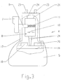
- plug contacts 23 see FIG. 3 contacted the in the handle 6 inserted energy storage 4 the electric motor 3 to the power supply.
- the power tool 1 has an actuating member 7 for actuating a switching means 8 (see FIG. 3) for the power supply of the electric motor 3.
- the actuator 7 is manually operated by the user against the force of a pressure spring 11 shown only schematically in Fig. 3 by a pressure movement, so as to turn on and off the power supply for the electric motor 3.
- both the switching means 8 and the actuator 7 in and / or the energy storage housing 5, as shown in FIG. 3 can be seen, such that no further switching means and / or actuator for switching the power supply of the electric motor. 3 is arranged on the power tool housing 2.
- the actuating member 7 acts now in its movement directly and / or indirectly actuated on the switching means 8 a.
- the switch means 8 shown schematically in FIG. 3 is a conventional electrical switch having an electromechanical contact system 10.
- the actuating member 7 acts via a plunger 9, which movably leads into the interior of the energy storage housing 5. on the switching means 8 a.
- the electromechanical contact system 10 is configured together with the actuator 7 as a self-contained, preassembled unit, so that the switching means 8 is used in the manner of a complete electrical switch in the energy storage housing 5 during assembly of the energy storage device 4.
- the switching means 8 can just as well be a sensor switch with a sensor 12, such as a force sensor, a Hall sensor, a magnetoresistive sensor, a capacitive pressure sensor or the like, as can be seen in FIG.
- the tappet 9 having actuator 7 is again against the force of a compression spring 11 movable.
- a cooperating both with the actuator 7 and the switching means 8 and / or operatively engageable transmission means 13 transmits the movement of the actuator 7 to the switching means 8.
- a transmission means 13 is a leaf spring which is attached approximately centrally to a clamping point 14. One end of the leaf spring 13 is in communication with the plunger 9, while the other end of the leaf spring 13 acts on the sensor 12 via an elastic element 15.
- the sensor 12 is mounted approximately perpendicularly projecting on a printed circuit board 19.
- the switching means 8 may be configured together with the sensor 12 and optionally the circuit board 19 and the actuator 7 as an independent, preassembled unit, which is not shown in detail.
- the actuating member 7 protrudes out of the power tool housing 2 for the user to access manually. Therefore, the actuating member 7 according to FIG. 3 or FIG. 5 also projects out of the energy storage housing 5, wherein the plunger 9 leading into the energy storage housing 5 transmits its movement to the switching means 8 on the actuating member 7.
- the energy storage 4 is inserted into the power tool housing 2 on the handle 6 by means of insertion.
- Fig. 5 in the manner of a panel on the energy storage housing 5 closes the receptacle 16 in the retracted state of the energy storage 4.
- the cover 17 is associated with the actuator 7 and arranged below the plunger 9, such that the receptacle 16 after insertion of the energy storage housing 5 is covered in the power tool housing 2 according to FIG. 2.
- the energy storage housing 5 itself is designed in the manner of a handle 6 'for the power tool housing 2.
- the power tool housing 2 requires no further handle, but the energy storage housing 4 takes over this function.
- the handle 6 'containing the energy store 4 can be exchangeably fastened to the part of the power tool housing 2 containing the electric motor 3.
- plug contacts 23 located in the handle 6 'energy storage 4 plug contacts 23 which can be connected to mating contacts 25 in the power tool housing 2. From the mating contacts 25 then lead leads 26 for the electrical voltage to the electric motor.
- the rotational speed of the electric motor 3 can be controlled and / or regulated, so that the rotational speed is set in accordance with the displacement of the actuating member 7, which is generated by the user by pressing the actuator 7.
- the switching means 8 is then connected to an electronics 18 schematically indicated in FIG. 3 or 5 for controlling and / or regulating the voltage supply for the electric motor 3.
- the electronics 18 may be designed in the manner of a pulse width modulation circuit, if the electric motor 3 is operated with DC voltage. In a driven with AC electric motor 3 is a phase control, phase control o. The like.
- As electronics 18. Of course, the electric motor 3 with the adjustment of the actuator 7 associated torque o. The like. By means of the electronics 18 can be operated.
- the electronics 18 is also arranged in the energy storage housing 5, namely on the circuit board 19. On the circuit board 19 can simultaneously be used for charging the energy storage 4 charging electronics 20, wherein optionally electrical and / or electrical components for both the electronics 18th as well as for the charging electronics 20 are used simultaneously. Electrical lines 24 in the energy storage housing 5 are used for electrical connection between the switching means 8 and / or the circuit board 19 with the electronics 8 and optionally the charging electronics 20 and the plug contacts 23rd
- further adjusting means for controlling and / or regulating the power supply of the electric motor 3 are still on the power tool housing. 2 arranged.
- these manually operated by the user adjustment means 27 are also arranged on the energy storage housing 5, as indicated in Fig. 6 schematically.
- the adjusting means 27 may be a potentiometer, a tap changer or the like, the adjusting means 27 serving, for example, for presetting a maximum speed, a maximum torque or the like for the operation of the electric motor 3.
- the switch assembly for a power tool 1 thus consists of the located in and / or the energy storage housing 5 actuator 7 and / or located in the energy storage housing 5 switching means 8, wherein the actuating member 7 and the switching means 8 may be configured in the manner of a preassembled unit, which in turn is inserted into the energy storage housing 5.
- the invention is not limited to the described and illustrated embodiment. Rather, it also encompasses all expert developments within the scope of the invention defined by the claims.
- the invention in particular the switch arrangement described, not only in cordless power tools but also in other electrical appliances, which are provided with a particular changeable designed energy storage, such as electrical household appliances, electrical gardening equipment, machine tools o. The like., In a variety of ways use ,
Landscapes
- Engineering & Computer Science (AREA)
- Mechanical Engineering (AREA)
- Battery Mounting, Suspending (AREA)
- Portable Power Tools In General (AREA)
- Harvester Elements (AREA)
Applications Claiming Priority (1)
| Application Number | Priority Date | Filing Date | Title |
|---|---|---|---|
| DE102005054498 | 2005-11-16 |
Publications (2)
| Publication Number | Publication Date |
|---|---|
| EP1788597A1 true EP1788597A1 (fr) | 2007-05-23 |
| EP1788597B1 EP1788597B1 (fr) | 2008-12-31 |
Family
ID=37758652
Family Applications (1)
| Application Number | Title | Priority Date | Filing Date |
|---|---|---|---|
| EP06023399A Not-in-force EP1788597B1 (fr) | 2005-11-16 | 2006-11-10 | Outil à main électrique alimenté par batterie |
Country Status (3)
| Country | Link |
|---|---|
| EP (1) | EP1788597B1 (fr) |
| AT (1) | ATE419636T1 (fr) |
| DE (1) | DE502006002480D1 (fr) |
Cited By (4)
| Publication number | Priority date | Publication date | Assignee | Title |
|---|---|---|---|---|
| EP2008776A1 (fr) * | 2007-06-27 | 2008-12-31 | Marquardt GmbH | Outil électrique, en particulier outil électrique à batterie |
| WO2014039868A3 (fr) * | 2012-09-07 | 2014-05-01 | Robert Bosch Gmbh | Commutateur à glissière pour outil mécanique |
| US20150182230A1 (en) * | 2012-05-23 | 2015-07-02 | Stryker Corporation | Battery and control module for both energizing and controlling a powered surgical tool that is releasably attached to the module |
| ITUB20160783A1 (it) * | 2016-02-16 | 2017-08-16 | Tech4Sea Srl | Sistema di attuazione per utensili elettrici |
Families Citing this family (2)
| Publication number | Priority date | Publication date | Assignee | Title |
|---|---|---|---|---|
| CN108927855A (zh) * | 2018-08-01 | 2018-12-04 | 苏州穹力机械科技有限公司 | 手动开孔机 |
| EP3970175A4 (fr) | 2019-05-13 | 2023-01-11 | Milwaukee Electric Tool Corporation | Détente sans contact à capteur magnétique de rotation pour outil électrique |
Citations (8)
| Publication number | Priority date | Publication date | Assignee | Title |
|---|---|---|---|---|
| US3973179A (en) * | 1974-08-23 | 1976-08-03 | The Black And Decker Manufacturing Company | Modular cordless tools |
| GB1515390A (en) * | 1974-08-23 | 1978-06-21 | Black & Decker Mfg Co | Battery-operated electrical appliance of modular construction |
| EP0726586A2 (fr) * | 1995-02-10 | 1996-08-14 | Marquardt GmbH | Interrupteur électrique, en particulier interrupteur pour outils électriques à batterie |
| DE19913712A1 (de) * | 1998-04-04 | 1999-10-07 | Marquardt Gmbh | Elektrischer Schalter |
| EP1075906A2 (fr) * | 1999-07-14 | 2001-02-14 | Black & Decker Inc. | Bloc de batteries amovible pour outils électriques |
| US20030089511A1 (en) * | 2001-11-12 | 2003-05-15 | Yukio Tsuneda | Electric tool |
| DE10246761A1 (de) * | 2002-10-07 | 2004-04-15 | Hilti Ag | Batteriebetriebene Elektrohandwerkzeugmaschine |
| EP1439037A2 (fr) * | 2002-12-19 | 2004-07-21 | HILTI Aktiengesellschaft | Machine-outil électrique à main avec commutateur manuel électrique sans contact |
-
2006
- 2006-11-10 AT AT06023399T patent/ATE419636T1/de not_active IP Right Cessation
- 2006-11-10 EP EP06023399A patent/EP1788597B1/fr not_active Not-in-force
- 2006-11-10 DE DE502006002480T patent/DE502006002480D1/de active Active
Patent Citations (8)
| Publication number | Priority date | Publication date | Assignee | Title |
|---|---|---|---|---|
| US3973179A (en) * | 1974-08-23 | 1976-08-03 | The Black And Decker Manufacturing Company | Modular cordless tools |
| GB1515390A (en) * | 1974-08-23 | 1978-06-21 | Black & Decker Mfg Co | Battery-operated electrical appliance of modular construction |
| EP0726586A2 (fr) * | 1995-02-10 | 1996-08-14 | Marquardt GmbH | Interrupteur électrique, en particulier interrupteur pour outils électriques à batterie |
| DE19913712A1 (de) * | 1998-04-04 | 1999-10-07 | Marquardt Gmbh | Elektrischer Schalter |
| EP1075906A2 (fr) * | 1999-07-14 | 2001-02-14 | Black & Decker Inc. | Bloc de batteries amovible pour outils électriques |
| US20030089511A1 (en) * | 2001-11-12 | 2003-05-15 | Yukio Tsuneda | Electric tool |
| DE10246761A1 (de) * | 2002-10-07 | 2004-04-15 | Hilti Ag | Batteriebetriebene Elektrohandwerkzeugmaschine |
| EP1439037A2 (fr) * | 2002-12-19 | 2004-07-21 | HILTI Aktiengesellschaft | Machine-outil électrique à main avec commutateur manuel électrique sans contact |
Cited By (11)
| Publication number | Priority date | Publication date | Assignee | Title |
|---|---|---|---|---|
| EP2008776A1 (fr) * | 2007-06-27 | 2008-12-31 | Marquardt GmbH | Outil électrique, en particulier outil électrique à batterie |
| US20150182230A1 (en) * | 2012-05-23 | 2015-07-02 | Stryker Corporation | Battery and control module for both energizing and controlling a powered surgical tool that is releasably attached to the module |
| CN107496003A (zh) * | 2012-05-23 | 2017-12-22 | 史赛克公司 | 具有重叠手术工具单元的可再充电位置的、用于手术工具单元的电池和控制模块 |
| US10076340B2 (en) * | 2012-05-23 | 2018-09-18 | Stryker Corporation | Surgical tool system with a tool unit that includes a power generating unit and a battery and control module that is releasably attached to the tool unit for energizing and controlling the power generating unit |
| CN107496003B (zh) * | 2012-05-23 | 2021-02-09 | 史赛克公司 | 具有重叠手术工具单元的可再充电位置的、用于手术工具单元的电池和控制模块 |
| US11103254B2 (en) | 2012-05-23 | 2021-08-31 | Stryker Corporation | Surgical tool system with a battery and control module having a driver capable of reusing contacts |
| US20210369285A1 (en) * | 2012-05-23 | 2021-12-02 | Stryker Corporation | Surgical Tool System With Interchangeable Battery and Control Modules |
| US12029439B2 (en) * | 2012-05-23 | 2024-07-09 | Stryker Corporation | Surgical tool system with interchangeable battery and control modules |
| WO2014039868A3 (fr) * | 2012-09-07 | 2014-05-01 | Robert Bosch Gmbh | Commutateur à glissière pour outil mécanique |
| US9242362B2 (en) | 2012-09-07 | 2016-01-26 | Robert Bosch Gmbh | Slide switch for a power tool |
| ITUB20160783A1 (it) * | 2016-02-16 | 2017-08-16 | Tech4Sea Srl | Sistema di attuazione per utensili elettrici |
Also Published As
| Publication number | Publication date |
|---|---|
| EP1788597B1 (fr) | 2008-12-31 |
| ATE419636T1 (de) | 2009-01-15 |
| DE502006002480D1 (de) | 2009-02-12 |
Similar Documents
| Publication | Publication Date | Title |
|---|---|---|
| EP1765557B1 (fr) | Outil electrique, notamment outil electrique sans fil | |
| EP0182986B1 (fr) | Dispositif de serrage actionné par moteur avec réglage du couple variable | |
| EP1788597B1 (fr) | Outil à main électrique alimenté par batterie | |
| EP2008776B1 (fr) | Outil électrique, en particulier outil électrique à batterie | |
| DE102014217863A1 (de) | Handwerkzeugmaschine | |
| EP2380182B1 (fr) | Commutateur électrique | |
| DE112017006677T5 (de) | Schraubendreher | |
| EP2240304A1 (fr) | Outil électrique | |
| DE102006052366A1 (de) | Elektrowerkzeug, insbesondere Akku-Elektrowerkzeug | |
| DE102005035046B4 (de) | Elektrowerkzeug | |
| DE102009009965B4 (de) | Elektrischer Schalter, insbesondere Elektrowerkzeugschalter | |
| DE112017006683T5 (de) | Halterungsanordnung und elektrisches Werkzeug mit solcher Halterungsanordnung | |
| EP2406801B1 (fr) | Interrupteur électrique | |
| DE102010034377A1 (de) | Elektrischer Schalter | |
| DE3324545A1 (de) | Elektromotorisch betriebenes handgeraet | |
| EP2162979B1 (fr) | Dispositif de commande pour moteur électrique | |
| DE102007031016A1 (de) | Elektrischer Schalter | |
| EP2195917B1 (fr) | Montage électrique pour un outil électrique | |
| WO2009065390A1 (fr) | Outil électrique à main | |
| EP1472708B1 (fr) | Dispositif de commutation electrique pour un outil electrique a main | |
| EP0085730B1 (fr) | Commutateur à pression bipolaire avec dispositif électronique de commande et de réglage destiné à étre monté dans un appareil électrique actionné à la main | |
| EP3822035A1 (fr) | Dispositif de poignée pour une machine-outil | |
| DE102005032608A1 (de) | Elektrowerkzeug, insbesondere Akku-Elektrowerkzeug | |
| DE102006053502A1 (de) | Elektrowerkzeug, insbesondere Akku-Elektrowerkzeug | |
| DE102009004320B4 (de) | Elektrischer Schalter |
Legal Events
| Date | Code | Title | Description |
|---|---|---|---|
| PUAI | Public reference made under article 153(3) epc to a published international application that has entered the european phase |
Free format text: ORIGINAL CODE: 0009012 |
|
| AK | Designated contracting states |
Kind code of ref document: A1 Designated state(s): AT BE BG CH CY CZ DE DK EE ES FI FR GB GR HU IE IS IT LI LT LU LV MC NL PL PT RO SE SI SK TR |
|
| AX | Request for extension of the european patent |
Extension state: AL BA HR MK YU |
|
| 17P | Request for examination filed |
Effective date: 20070817 |
|
| 17Q | First examination report despatched |
Effective date: 20070920 |
|
| AKX | Designation fees paid |
Designated state(s): AT BE BG CH CY CZ DE DK EE ES FI FR GB GR HU IE IS IT LI LT LU LV MC NL PL PT RO SE SI SK TR |
|
| GRAP | Despatch of communication of intention to grant a patent |
Free format text: ORIGINAL CODE: EPIDOSNIGR1 |
|
| GRAS | Grant fee paid |
Free format text: ORIGINAL CODE: EPIDOSNIGR3 |
|
| GRAA | (expected) grant |
Free format text: ORIGINAL CODE: 0009210 |
|
| AK | Designated contracting states |
Kind code of ref document: B1 Designated state(s): AT BE BG CH CY CZ DE DK EE ES FI FR GB GR HU IE IS IT LI LT LU LV MC NL PL PT RO SE SI SK TR |
|
| REG | Reference to a national code |
Ref country code: CH Ref legal event code: EP Ref country code: GB Ref legal event code: FG4D Free format text: NOT ENGLISH |
|
| REF | Corresponds to: |
Ref document number: 502006002480 Country of ref document: DE Date of ref document: 20090212 Kind code of ref document: P |
|
| REG | Reference to a national code |
Ref country code: IE Ref legal event code: FG4D Free format text: LANGUAGE OF EP DOCUMENT: GERMAN |
|
| REG | Reference to a national code |
Ref country code: CH Ref legal event code: NV Representative=s name: KELLER & PARTNER PATENTANWAELTE AG |
|
| PG25 | Lapsed in a contracting state [announced via postgrant information from national office to epo] |
Ref country code: SI Free format text: LAPSE BECAUSE OF FAILURE TO SUBMIT A TRANSLATION OF THE DESCRIPTION OR TO PAY THE FEE WITHIN THE PRESCRIBED TIME-LIMIT Effective date: 20081231 Ref country code: PL Free format text: LAPSE BECAUSE OF FAILURE TO SUBMIT A TRANSLATION OF THE DESCRIPTION OR TO PAY THE FEE WITHIN THE PRESCRIBED TIME-LIMIT Effective date: 20081231 Ref country code: FI Free format text: LAPSE BECAUSE OF FAILURE TO SUBMIT A TRANSLATION OF THE DESCRIPTION OR TO PAY THE FEE WITHIN THE PRESCRIBED TIME-LIMIT Effective date: 20081231 Ref country code: LV Free format text: LAPSE BECAUSE OF FAILURE TO SUBMIT A TRANSLATION OF THE DESCRIPTION OR TO PAY THE FEE WITHIN THE PRESCRIBED TIME-LIMIT Effective date: 20081231 |
|
| PG25 | Lapsed in a contracting state [announced via postgrant information from national office to epo] |
Ref country code: LT Free format text: LAPSE BECAUSE OF FAILURE TO SUBMIT A TRANSLATION OF THE DESCRIPTION OR TO PAY THE FEE WITHIN THE PRESCRIBED TIME-LIMIT Effective date: 20081231 Ref country code: EE Free format text: LAPSE BECAUSE OF FAILURE TO SUBMIT A TRANSLATION OF THE DESCRIPTION OR TO PAY THE FEE WITHIN THE PRESCRIBED TIME-LIMIT Effective date: 20081231 Ref country code: RO Free format text: LAPSE BECAUSE OF FAILURE TO SUBMIT A TRANSLATION OF THE DESCRIPTION OR TO PAY THE FEE WITHIN THE PRESCRIBED TIME-LIMIT Effective date: 20081231 Ref country code: ES Free format text: LAPSE BECAUSE OF FAILURE TO SUBMIT A TRANSLATION OF THE DESCRIPTION OR TO PAY THE FEE WITHIN THE PRESCRIBED TIME-LIMIT Effective date: 20090411 |
|
| REG | Reference to a national code |
Ref country code: IE Ref legal event code: FD4D |
|
| PG25 | Lapsed in a contracting state [announced via postgrant information from national office to epo] |
Ref country code: IS Free format text: LAPSE BECAUSE OF FAILURE TO SUBMIT A TRANSLATION OF THE DESCRIPTION OR TO PAY THE FEE WITHIN THE PRESCRIBED TIME-LIMIT Effective date: 20090430 Ref country code: SE Free format text: LAPSE BECAUSE OF FAILURE TO SUBMIT A TRANSLATION OF THE DESCRIPTION OR TO PAY THE FEE WITHIN THE PRESCRIBED TIME-LIMIT Effective date: 20090331 Ref country code: CZ Free format text: LAPSE BECAUSE OF FAILURE TO SUBMIT A TRANSLATION OF THE DESCRIPTION OR TO PAY THE FEE WITHIN THE PRESCRIBED TIME-LIMIT Effective date: 20081231 Ref country code: PT Free format text: LAPSE BECAUSE OF FAILURE TO SUBMIT A TRANSLATION OF THE DESCRIPTION OR TO PAY THE FEE WITHIN THE PRESCRIBED TIME-LIMIT Effective date: 20090601 |
|
| PG25 | Lapsed in a contracting state [announced via postgrant information from national office to epo] |
Ref country code: SK Free format text: LAPSE BECAUSE OF FAILURE TO SUBMIT A TRANSLATION OF THE DESCRIPTION OR TO PAY THE FEE WITHIN THE PRESCRIBED TIME-LIMIT Effective date: 20081231 |
|
| PG25 | Lapsed in a contracting state [announced via postgrant information from national office to epo] |
Ref country code: IE Free format text: LAPSE BECAUSE OF FAILURE TO SUBMIT A TRANSLATION OF THE DESCRIPTION OR TO PAY THE FEE WITHIN THE PRESCRIBED TIME-LIMIT Effective date: 20081231 Ref country code: DK Free format text: LAPSE BECAUSE OF FAILURE TO SUBMIT A TRANSLATION OF THE DESCRIPTION OR TO PAY THE FEE WITHIN THE PRESCRIBED TIME-LIMIT Effective date: 20081231 |
|
| PLBE | No opposition filed within time limit |
Free format text: ORIGINAL CODE: 0009261 |
|
| STAA | Information on the status of an ep patent application or granted ep patent |
Free format text: STATUS: NO OPPOSITION FILED WITHIN TIME LIMIT |
|
| 26N | No opposition filed |
Effective date: 20091001 |
|
| PG25 | Lapsed in a contracting state [announced via postgrant information from national office to epo] |
Ref country code: BG Free format text: LAPSE BECAUSE OF FAILURE TO SUBMIT A TRANSLATION OF THE DESCRIPTION OR TO PAY THE FEE WITHIN THE PRESCRIBED TIME-LIMIT Effective date: 20090331 |
|
| BERE | Be: lapsed |
Owner name: MARQUARDT G.M.B.H. Effective date: 20091130 |
|
| PG25 | Lapsed in a contracting state [announced via postgrant information from national office to epo] |
Ref country code: MC Free format text: LAPSE BECAUSE OF NON-PAYMENT OF DUE FEES Effective date: 20091130 |
|
| REG | Reference to a national code |
Ref country code: FR Ref legal event code: ST Effective date: 20100730 |
|
| PG25 | Lapsed in a contracting state [announced via postgrant information from national office to epo] |
Ref country code: BE Free format text: LAPSE BECAUSE OF NON-PAYMENT OF DUE FEES Effective date: 20091130 Ref country code: GR Free format text: LAPSE BECAUSE OF FAILURE TO SUBMIT A TRANSLATION OF THE DESCRIPTION OR TO PAY THE FEE WITHIN THE PRESCRIBED TIME-LIMIT Effective date: 20090401 Ref country code: FR Free format text: LAPSE BECAUSE OF NON-PAYMENT OF DUE FEES Effective date: 20091130 |
|
| PG25 | Lapsed in a contracting state [announced via postgrant information from national office to epo] |
Ref country code: AT Free format text: LAPSE BECAUSE OF NON-PAYMENT OF DUE FEES Effective date: 20091110 |
|
| PG25 | Lapsed in a contracting state [announced via postgrant information from national office to epo] |
Ref country code: IT Free format text: LAPSE BECAUSE OF FAILURE TO SUBMIT A TRANSLATION OF THE DESCRIPTION OR TO PAY THE FEE WITHIN THE PRESCRIBED TIME-LIMIT Effective date: 20081231 |
|
| PG25 | Lapsed in a contracting state [announced via postgrant information from national office to epo] |
Ref country code: LU Free format text: LAPSE BECAUSE OF NON-PAYMENT OF DUE FEES Effective date: 20091110 |
|
| PG25 | Lapsed in a contracting state [announced via postgrant information from national office to epo] |
Ref country code: HU Free format text: LAPSE BECAUSE OF FAILURE TO SUBMIT A TRANSLATION OF THE DESCRIPTION OR TO PAY THE FEE WITHIN THE PRESCRIBED TIME-LIMIT Effective date: 20090701 |
|
| GBPC | Gb: european patent ceased through non-payment of renewal fee |
Effective date: 20101110 |
|
| PG25 | Lapsed in a contracting state [announced via postgrant information from national office to epo] |
Ref country code: TR Free format text: LAPSE BECAUSE OF FAILURE TO SUBMIT A TRANSLATION OF THE DESCRIPTION OR TO PAY THE FEE WITHIN THE PRESCRIBED TIME-LIMIT Effective date: 20081231 |
|
| PG25 | Lapsed in a contracting state [announced via postgrant information from national office to epo] |
Ref country code: CY Free format text: LAPSE BECAUSE OF FAILURE TO SUBMIT A TRANSLATION OF THE DESCRIPTION OR TO PAY THE FEE WITHIN THE PRESCRIBED TIME-LIMIT Effective date: 20081231 |
|
| PG25 | Lapsed in a contracting state [announced via postgrant information from national office to epo] |
Ref country code: GB Free format text: LAPSE BECAUSE OF NON-PAYMENT OF DUE FEES Effective date: 20101110 |
|
| REG | Reference to a national code |
Ref country code: CH Ref legal event code: PCAR Free format text: NEW ADDRESS: EIGERSTRASSE 2 POSTFACH, 3000 BERN 14 (CH) |
|
| PGFP | Annual fee paid to national office [announced via postgrant information from national office to epo] |
Ref country code: NL Payment date: 20181120 Year of fee payment: 13 |
|
| PGFP | Annual fee paid to national office [announced via postgrant information from national office to epo] |
Ref country code: CH Payment date: 20181120 Year of fee payment: 13 |
|
| REG | Reference to a national code |
Ref country code: CH Ref legal event code: PL |
|
| REG | Reference to a national code |
Ref country code: NL Ref legal event code: MM Effective date: 20191201 |
|
| PG25 | Lapsed in a contracting state [announced via postgrant information from national office to epo] |
Ref country code: CH Free format text: LAPSE BECAUSE OF NON-PAYMENT OF DUE FEES Effective date: 20191130 Ref country code: LI Free format text: LAPSE BECAUSE OF NON-PAYMENT OF DUE FEES Effective date: 20191130 |
|
| REG | Reference to a national code |
Ref country code: DE Ref legal event code: R082 Ref document number: 502006002480 Country of ref document: DE Representative=s name: JOSTARNDT PATENTANWALTS-AG, DE |
|
| PG25 | Lapsed in a contracting state [announced via postgrant information from national office to epo] |
Ref country code: NL Free format text: LAPSE BECAUSE OF NON-PAYMENT OF DUE FEES Effective date: 20191201 |
|
| PGFP | Annual fee paid to national office [announced via postgrant information from national office to epo] |
Ref country code: DE Payment date: 20211130 Year of fee payment: 16 |
|
| REG | Reference to a national code |
Ref country code: DE Ref legal event code: R119 Ref document number: 502006002480 Country of ref document: DE |
|
| PG25 | Lapsed in a contracting state [announced via postgrant information from national office to epo] |
Ref country code: DE Free format text: LAPSE BECAUSE OF NON-PAYMENT OF DUE FEES Effective date: 20230601 |