EP1788339A2 - Wärmetauscher - Google Patents
Wärmetauscher Download PDFInfo
- Publication number
- EP1788339A2 EP1788339A2 EP06023125A EP06023125A EP1788339A2 EP 1788339 A2 EP1788339 A2 EP 1788339A2 EP 06023125 A EP06023125 A EP 06023125A EP 06023125 A EP06023125 A EP 06023125A EP 1788339 A2 EP1788339 A2 EP 1788339A2
- Authority
- EP
- European Patent Office
- Prior art keywords
- heat exchanger
- plate
- block
- header
- flow
- Prior art date
- Legal status (The legal status is an assumption and is not a legal conclusion. Google has not performed a legal analysis and makes no representation as to the accuracy of the status listed.)
- Granted
Links
Images
Classifications
-
- F—MECHANICAL ENGINEERING; LIGHTING; HEATING; WEAPONS; BLASTING
- F28—HEAT EXCHANGE IN GENERAL
- F28F—DETAILS OF HEAT-EXCHANGE AND HEAT-TRANSFER APPARATUS, OF GENERAL APPLICATION
- F28F9/00—Casings; Header boxes; Auxiliary supports for elements; Auxiliary members within casings
- F28F9/02—Header boxes; End plates
-
- F—MECHANICAL ENGINEERING; LIGHTING; HEATING; WEAPONS; BLASTING
- F28—HEAT EXCHANGE IN GENERAL
- F28D—HEAT-EXCHANGE APPARATUS, NOT PROVIDED FOR IN ANOTHER SUBCLASS, IN WHICH THE HEAT-EXCHANGE MEDIA DO NOT COME INTO DIRECT CONTACT
- F28D9/00—Heat-exchange apparatus having stationary plate-like or laminated conduit assemblies for both heat-exchange media, the media being in contact with different sides of a conduit wall
-
- F—MECHANICAL ENGINEERING; LIGHTING; HEATING; WEAPONS; BLASTING
- F28—HEAT EXCHANGE IN GENERAL
- F28F—DETAILS OF HEAT-EXCHANGE AND HEAT-TRANSFER APPARATUS, OF GENERAL APPLICATION
- F28F9/00—Casings; Header boxes; Auxiliary supports for elements; Auxiliary members within casings
- F28F9/02—Header boxes; End plates
- F28F9/0246—Arrangements for connecting header boxes with flow lines
-
- F—MECHANICAL ENGINEERING; LIGHTING; HEATING; WEAPONS; BLASTING
- F28—HEAT EXCHANGE IN GENERAL
- F28F—DETAILS OF HEAT-EXCHANGE AND HEAT-TRANSFER APPARATUS, OF GENERAL APPLICATION
- F28F9/00—Casings; Header boxes; Auxiliary supports for elements; Auxiliary members within casings
- F28F9/02—Header boxes; End plates
- F28F9/026—Header boxes; End plates with static flow control means, e.g. with means for uniformly distributing heat exchange media into conduits
- F28F9/0265—Header boxes; End plates with static flow control means, e.g. with means for uniformly distributing heat exchange media into conduits by using guiding means or impingement means inside the header box
-
- F—MECHANICAL ENGINEERING; LIGHTING; HEATING; WEAPONS; BLASTING
- F28—HEAT EXCHANGE IN GENERAL
- F28D—HEAT-EXCHANGE APPARATUS, NOT PROVIDED FOR IN ANOTHER SUBCLASS, IN WHICH THE HEAT-EXCHANGE MEDIA DO NOT COME INTO DIRECT CONTACT
- F28D21/00—Heat-exchange apparatus not covered by any of the groups F28D1/00 - F28D20/00
- F28D2021/0019—Other heat exchangers for particular applications; Heat exchange systems not otherwise provided for
- F28D2021/0033—Other heat exchangers for particular applications; Heat exchange systems not otherwise provided for for cryogenic applications
Definitions
- the invention relates to a plate heat exchanger having a heat exchanger block having a plurality of heat exchange passages, the heat exchanger block having a header extending over at least a portion of one side of the heat exchanger block and providing flow communication between a portion of the heat exchange passages and a fluid port is provided, wherein the fluid port is arranged substantially perpendicular to the side of the heat exchanger block, over which the header extends.
- the heat exchanger block of a plate heat exchanger consists of several layers of heat exchange passages, which are each delimited by separating plates against each other. End strips and cover plates form the outer frame of the heat exchanger block. Within a layer, further separating strips can be provided which separate heat exchange passages for different material flows from one another.
- the initially made of loose components heat exchanger block is then soldered in a brazing furnace, so that all components are sealed together.
- headers are welded over the inlet and outlet openings of the heat exchange passages, which are provided with a fluid connection.
- Semi-cylindrical trays are usually used as headers.
- the fluid connection is formed by pipe sockets, which are arranged in the half-cylinder jacket of the header with respect to the inlet and outlet openings. At this pipe socket, the pipes for the incoming and outgoing fluid flows are connected.
- plate heat exchangers can be used for the simultaneous heat exchange of many fluid streams.
- appropriate headers are then to be attached above the respective inlet and outlet openings of the heat exchange passages and with pipelines to provide.
- the piping of the plate heat exchanger is very complex and expensive in this case.
- the plate heat exchanger according to the invention has a heat exchanger block with a plurality of heat exchange passages.
- the heat exchange passages can be divided into specific groups, the heat exchange passages of a group each serving to guide a particular fluid flow. Via the inlet and outlet openings in the heat exchange passages of a group headers are each mounted so that a flow connection between these passages is made.
- the header sometimes referred to as a collector covers a part of a heat exchanger block side and forms with this a closed space into which the inlet or outlet openings of a group of heat exchange passages open.
- the header is provided with a fluid connection, which is arranged substantially perpendicular to the side of the heat exchanger block, over which the header extends.
- the headers and in particular the fluid connection it becomes possible to provide all the fluid connections on two opposite sides of the heat exchanger block. Often it is even possible to design the plate heat exchanger so that all fluid connections are on the same side of the heat exchanger block.
- the pipelines for supplying and discharging the material flows brought into heat exchange with one another therefore no longer have to be led around the heat exchanger block in a complex manner.
- the piping effort is significantly reduced.
- the header is not only for distributing the supplied fluid flow to the heat exchange passages or Collecting the exiting from the heat exchange passages fluid, but also for supplying or discharging the corresponding fluid streams.
- Object of the present invention is to further improve a plate heat exchanger of the type mentioned.
- This object is achieved in that a means for guiding the flow is arranged in the interior of the pipeline immediately before its end.
- a means for guiding the flow is now arranged in the inlet connection, that is to say at the end of the pipeline at which the fluid connection is located. Surprisingly, it is possible by such, relatively inexpensive guide in the inlet nozzle to keep the separation vortices of the passages and thus to improve the uniform distribution in the header significantly.
- This means is arranged "at the end of the pipeline". This can, but does not have to mean, that the agent reaches the end of the pipeline, ie the fluid connection. There may also be a small distance between the end of the means facing the fluid connection and the fluid connection. In any case, this distance is small compared to the length of the pipeline and is preferably substantially smaller than the diameter of the pipeline and is preferably less than 100 mm, in particular less than 10 mm. If the pipeline is relatively short, the means can also run over the whole or essentially the entire pipeline.
- the headers preferably have a semicircular cross-section, in particular semi-cylindrical shells have proven to be suitable as headers.
- the fluid connection is then in one of the two semicircular base surfaces.
- the invention can also be applied to plate heat exchangers having a plurality of heat exchanger blocks. These will be on the in EP 1452817 A1 and EP 1471322 A1 manner described interconnected.
- a connection can also be made by means of a full pipe (cylindrical pipe).
- the means for guiding the flow can take any suitable form and, for example, have a curved plate.
- the means for guiding the flow comprises at least one flat plate and, for example, consists of a single or two or more interconnected flat plates. In a plurality of flat plates, these are preferably inclined to each other.
- the planar plate (s) forming the flow guide means has openings.
- the means for flow guidance consists of a single flat perforated plate.
- the or one or all flat plate (s) are solid, that is without or without substantial perforation, that is, the free hole cross-section is less than 20%, preferably less than 10%.
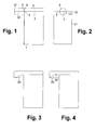
- the heat exchanger block (1) facing portion of the means (23) for flow guidance is formed as a plate and ends at an edge (4) of the heat exchanger block or in the vicinity and that in particular the central axis of the pipe through the block-side end the means (23) for flow guidance extends.
- These measures effectively prevent the formation of separation vortices on the edge of the block.
- Nearby here means that the distance between the block-side end of the plate and the edge of the block is in any case significantly smaller than the diameter of the pipeline, and is for example less than 100 mm, in particular less than 10 mm.
- a plate heat exchanger is shown schematically in two mutually perpendicular directions of view.
- it has a heat exchanger block 1 with a multiplicity of heat exchange passages, which are not shown in the figures for the sake of clarity.
- the inlet openings of a group of heat exchange passages are located in the area 2 of the upper wall 3 of the heat exchanger block 1.
- a semi-cylindrical header 6 is welded, which covers the inlet openings. (Of course, the heat exchanger block has further headers and inlet or outlet openings, which are not shown in the drawings.)
- the header 6 is designed as a semi-cylindrical shell with base 8.
- the base area 8 represents the "fluid connection”.
- the header 6 is connected to a pipeline 12, via which, in operation, the fluid to be introduced into the heat exchange passages flows from the left. (The pipe 12 continues to the left over the edge of Figure 1 away.)
- the pipe 12 is sealed to the header 6, so that the inflowing fluid flows through pipe 12 through the open base 8 in the header 6 and in the Header 6 is distributed to the corresponding heat exchange passages of the block 1.
- a guide plate 23 is arranged as "means for flow guidance".
- the baffle 23 may be formed for example by a flat metal sheet.
- the guide plate 23 is arranged on the cylinder axis of the pipeline and parallel to the surface 3 of the heat exchanger block 1, ie it runs directly onto the edge 4 of the block 1.
- the end of the baffle 23 can be welded to the block.
- the baffle is located exactly in front of the upper edge of the heat exchanger block 1 in area 2 and is therefore not specifically visible.
- the baffle may also have other shapes, with its block-side end should end at or near the edge 4 in all cases. Examples of such differently shaped flow control means are shown in the further drawings.
- Figure 3 shows a single plate 24 inclined with respect to the axis of the pipeline.
- Figure 4 shows a means comprising two mutually inclined plates 25, 26 joined together at one edge are; Of course, the two plates 25, 26 may be made of a single workpiece, for example by folding.
- the header 6 may be arranged deviating from the drawings along an edge 10 and / or on the broad side 11 of the block (1).
Landscapes
- Engineering & Computer Science (AREA)
- Physics & Mathematics (AREA)
- Thermal Sciences (AREA)
- Mechanical Engineering (AREA)
- General Engineering & Computer Science (AREA)
- Heat-Exchange Devices With Radiators And Conduit Assemblies (AREA)
- Details Of Heat-Exchange And Heat-Transfer (AREA)
Abstract
Description
- Die Erfindung betrifft einen Plattenwärmetauscher mit einem Wärmetauscherblock, der eine Vielzahl von Wärmeaustauschpassagen aufweist, wobei am Wärmetauscherblock ein Header angebracht ist, der sich über zumindest einen Teil einer Seite des Wärmetauscherblocks erstreckt und der eine Strömungsverbindung zwischen einem Teil der Wärmeaustauschpassagen herstellt und der mit einem Fluidanschluss versehen ist, wobei der Fluidanschluss im Wesentlichen senkrecht zu der Seite des Wärmetauscherblocks angeordnet ist, über der sich der Header erstreckt.
- Der Wärmetauscherblock eines Plattenwärmetauschers besteht aus mehreren Lagen von Wärmeaustauschpassagen, die jeweils durch Trennbleche gegeneinander abgegrenzt sind. Abschlussleisten sowie Deckbleche bilden den äußeren Rahmen des Wärmetauscherblocks. Innerhalb einer Lage können weitere Trennleisten vorgesehen sein, die Wärmeaustauschpassagen für unterschiedliche Stoffströme voneinander trennen.
- Der zunächst aus losen Bauteilen bestehende Wärmetauscherblock wird dann in einem Lötofen verlötet, so dass alle Bauteile miteinander dicht verbunden sind. Anschließend werden über den Ein- und Austrittsöffnungen der Wärmeaustauschpassagen Header aufgeschweißt, die mit einem Fluidanschluss versehen sind. Als Header werden üblicherweise halbzylindrische Schalen eingesetzt. Der Fluidanschluss wird durch Rohrstutzen gebildet, die in dem Halbzylindermantel des Headers gegenüber den Ein- bzw. Austrittsöffnungen angeordnet sind. An diese Rohrstutzen werden die Rohrleitungen für die zu- und abzuführenden Fluidströme angeschlossen.
- Durch geeignete Anordnung von Trennleisten können Plattenwärmetauscher für den gleichzeitigen Wärmeaustausch von vielen Fluidströmen eingesetzt werden. Für jeden der Fluidströme sind dann entsprechende Header über den jeweiligen Ein- und Austrittsöffnungen der Wärmeaustauschpassagen anzubringen und mit Rohrleitungen zu versehen. Die Verrohrung des Plattenwärmetauschers wird in diesem Fall sehr komplex und aufwändig.
- Der erfindungsgemäße Plattenwärmetauscher weist einen Wärmetauscherblock mit einer Vielzahl von Wärmeaustauschpassagen auf. Die Wärmeaustauschpassagen können in bestimmte Gruppen eingeteilt werden, wobei die Wärmeaustauschpassagen einer Gruppe jeweils zur Führung eines bestimmten Fluidstromes dienen. Über den Ein- bzw. Austrittsöffnungen in die Wärmeaustauschpassagen einer Gruppe sind Header jeweils so angebracht, dass eine Strömungsverbindung zwischen diesen Passagen hergestellt wird.
- Der Header, teilweise auch als Sammler bezeichnet, deckt einen Teil einer Wärmetauscherblockseite ab und bildet mit dieser einen abgeschlossenen Raum, in den die Ein- oder Austrittsöffnungen einer Gruppe von Wärmeaustauschpassagen münden. Erfindungsgemäß ist der Header mit einem Fluidanschluss versehen, der im Wesentlichen senkrecht zu der Seite des Wärmetauscherblocks angeordnet ist, über die sich der Header erstreckt.
- Aus
EP 1452817 A1 ist es bekannt, den Fluidanschluss, d. h. die Öffnung des Headers zu den jeweiligen Fluidstrom zu- bzw. abführenden Rohrleitungen, in einer Ebene anzuordnen, die im Wesentlichen senkrecht zu der Ebene liegt, in der sich die entsprechenden Ein- bzw. Austrittsöffnungen in die Wärmeaustauschpassagen befinden. Das heißt, der Fluidanschluss befindet sich gerade nicht direkt gegenüber den Ein- bzw. Austrittsöffnungen. - Durch diese Ausführung der Header und insbesondere des Fluidanschlusses wird es möglich, alle Fluidanschlüsse auf zwei gegenüberliegenden Seiten des Wärmetauscherblocks, vorzusehen. Häufig ist es sogar möglich, den Plattenwärmetauscher so zu gestalten, dass sich alle Fluidanschlüsse auf derselben Seite des Wärmetauscherblocks befinden. Die Rohrleitungen zum Zu- und Abführen der miteinander in Wärmetausch gebrachten Stoffströme müssen daher nicht mehr aufwändig um den Wärmetauscherblock herumgeführt werden. Der Verrohrungsaufwand wird wesentlich verringert. Der Header dient nicht nur zum Verteilen des zugeführten Fluidstromes auf die Wärmeaustauschpassagen bzw. zum Sammeln des aus den Wärmeaustauschpassagen austretenden Fluids, sondern auch zum Zu- bzw. Abführen der entsprechenden Fluidströme.
- Aufgabe der vorliegenden Erfindung ist es, einen Plattenwärmetauscher der eingangs genannten Art weiter zu verbessern.
- Diese Aufgabe wird dadurch gelöst, dass im Inneren der Rohrleitung unmittelbar vor ihrem Ende ein Mittel zur Strömungsführung angeordnet ist.
- Im Rahmen der Erfindung hat sich herausgestellt, dass es sich an dem Fluidanschluss, also am Übergang zwischen Rohrleitung und Header an der Blockkante zu Ablösewirbeln kommen kann, die zu einer Ungleichverteilung der Strömung in den Passagen führt. Diese Ungleichverteilung kann zu einer thermischen Minderleistung und auch zu zusätzlichen thermischen Spannungen des Apparates führen. Erfindungsgemäß wird nun im Eintrittsstutzen, also an dem Ende der Rohrleitung, an der sich der Fluidanschluss befindet, ein Mittel zur Strömungsführung angeordnet. Überraschenderweise ist es durch eine derartige, relativ kostengünstige Leiteinrichtung im Eintrittsstutzen möglich, den Ablösewirbel von den Passagen fernzuhalten und damit die Gleichverteilung im Header wesentlich zu verbessern.
- Dieses Mittel ist "am Ende der Rohrleitung" angeordnet. Das kann, muss aber nicht heißen, dass das Mittel bis zum Ende der Rohrleitung, also bis zum Fluidanschluss reicht. Es kann auch ein geringer Abstand zwischen dem zum Fluidanschluss weisenden Ende des Mittels und dem Fluidanschluss liegen. Dieser Abstand ist jedenfalls gering im Vergleich zur Länge der Rohrleitung und vorzugsweise wesentlich kleiner als der Durchmesser der Rohrleitung und beträgt vorzugsweise weniger als 100 mm, insbesondere weniger als 10 mm. Ist die Rohrleitung relativ kurz, kann das Mittel auch über die ganze oder im Wesentlichen die ganze Rohrleitung verlaufen.
- Vorzugsweise besitzen die Header einen halbkreisförmigen Querschnitt, insbesondere haben sich halbzylindrische Schalen als Header bewährt. Bei einer solchen halbschalenförmigen Ausführung des Headers befindet sich der Fluidanschluss dann in einer der beiden halbkreisförmigen Grundflächen. Aus Festigkeitsgründen kann es vorteilhaft sein, die andere der Grundflächen nicht senkrecht, sondern beispielsweise schräg zum Halbzylindermantel zu orientieren.
- Die Erfindung kann auch bei Plattenwärmetauschern mit mehreren Wärmetauscherblöcken angewendet werden. Diese werden auf die in
EP 1452817 A1 undEP 1471322 A1 beschriebene Weise miteinander verbunden. Alternativ zu der Verbindung der Header zweier Blöcke mittels einer halbzylindrischen Rohrleitung kann eine solche Verbindung auch mittels eines Vollrohrs (zylindrische Rohrleitung) vorgenommen werden. In diesem Fall ist es vorteilhaft, das erfindungsgemäße Strömungsführungsmittel auch in dieser Verbindungsleitung einzusetzen, insbesondere in Form einer ebenen Platte, die von der Kante des ersten Blocks zu der Kante des zweiten Blocks führt, ggf. mit kleinen Spalten zwischen Platte und Kanten. - Grundsätzlich kann das Mittel zur Strömungsführung jede geeignete Form annehmen und beispielsweise ein gekrümmte Platte aufweisen. Fertigungstechnisch günstiger ist es jedoch, wenn das Mittel zur Strömungsführung mindestens eine ebene Platte aufweist und beispielsweise aus einer einzigen oder zwei oder mehr miteinander verbundenen ebenen Platten besteht. Bei einer Mehrzahl von ebenen Platten sind diese vorzugsweise gegeneinander geneigt.
- Vorzugsweise weist bzw. weisen die ebene(n) Platte(n), welche das Mittel zur Strömungsführung bildet bzw. bilden, Öffnungen auf. Im einfachsten Fall besteht das Mittel zur Strömungsführung aus einem einzigen ebenen Lochblech.
- Alternativ sind die oder eine oder alle ebene(n) Platte(n) massiv, das heißt ohne oder ohne wesentliche Lochung, das heißt der freie Lochquerschnitt ist kleiner als 20 %, vorzugsweise kleiner als 10 %.
- Es ist ferner günstig, wenn der dem Wärmetauscherblock (1) zugewandte Bereich des Mittels (23) zur Strömungsführung als Platte ausgebildet ist und an einer Kante (4) des Wärmetauscherblocks oder in deren Nähe endet und dass insbesondere die Mittelachse der Rohrleitung durch das blockseitige Ende des Mittels (23) zur Strömungsführung verläuft. Durch diese Maßnahmen wird besonders effektiv die Bildung von Ablösewirbeln an der Kante des Blocks verhindert. "In der Nähe" bedeutet hier, dass der Abstand zwischen blockseitigem Ende der Platte und der Kante des Blocks jedenfalls deutlich geringer ist als der Durchmesser der Rohrleitung, und beträgt beispielsweise weniger als 100 mm, insbesondere weniger als 10 mm.
- Die Erfindung sowie weitere Einzelheiten der Erfindung werden im Folgenden anhand von in den Zeichnungen schematisch dargestellten Ausführungsbeispielen näher erläutert. Hierbei zeigen:
- Figuren 1 und 2
- je eine Seitenansicht einer ersten Ausführungsform eines erfindungsgemäßen Wärmetauschers mit einem Header und einer Rohrleitung und
- Figuren 3 und 4
- zwei weitere Ausführungsformen eines erfindungsgemäßen Wärmetauscherblock.
- In den Figuren 1 und 2 ist ein Plattenwärmetauscher schematisch in zwei zueinander senkrechten Blickrichtungen dargestellt. Er weist in dem Ausführungsbeispiel einen Wärmetauscherblock 1 mit einer Vielzahl von Wärmeaustauschpassagen auf, die der Übersichtlichkeit halber in den Figuren nicht gezeigt sind. Die Eintrittsöffnungen einer Gruppe von Wärmeaustauschpassagen befinden sich in dem Bereich 2 der oberen Wand 3 des Wärmetauscherblocks 1. Auf die obere Wand 3 ist ein halbzylindrischer Header 6 aufgeschweißt, der die Eintrittsöffnungen überdeckt. (Selbstverständlich weist der Wärmetauscherblock weitere Header und Ein- beziehungsweise Austrittsöffnungen auf; diese sind in den Zeichnungen nicht dargestellt.)
- Der Header 6 ist als halbzylindrische Schale mit Grundfläche 8 ausgeführt. Die Grundfläche 8 stellt den "Fluidanschluss" dar. An dieser Stelle ist der Header 6 mit einer Rohrleitung 12 verbunden, über die im Betrieb das in die Wärmeaustauschpassagen einzuführende Fluid von links heranströmt. (Die Rohrleitung 12 setzt sich nach links über den Rand der Figur 1 hinweg fort.) Die Rohrleitung 12 ist mit dem Header 6 dicht verbunden, so dass das zuströmende Fluid über Rohrleitung 12 durch die offene Grundfläche 8 in den Header 6 strömt und in dem Header 6 auf die entsprechenden Wärmeaustauschpassagen des Blocks 1 verteilt wird.
- Gemäß der Erfindung ist im Inneren des zylinderförmigen Endstücks der Rohrleitung 12, das in den Zeichnungen dargestellt ist, ein Leitblech 23 als "Mittel zur Strömungsführung" angeordnet. Das Leitblech 23 kann beispielsweise durch ein ebenes Metallblech gebildet werden.
- In dem Beispiel von Figur 1 ist das Leitblech 23 auf der Zylinderachse der Rohrleitung und parallel zu der Oberfläche 3 des Wärmetauscherblocks 1 angeordnet, läuft also unmittelbar auf die Kante 4 des Blocks 1 zu. Im Gegensatz zu der Darstellung in Figur 1 kann das Ende des Leitblechs 23 an den Block angeschweißt werden. Vorzugsweise verbleibt jedoch ein kleiner Spalt 5 von weniger als 100 mm, vorzugsweise weniger als 10 mm, zum Beispiel etwa 5 mm Breite zwischen der Leitblechkante und dem Block zu lassen. (In Figur 2 liegt das Leitblech genau vor der oberen Kante des Wärmetauscherblocks 1 im Bereich 2 und ist daher nicht eigens sichtbar.)
- Das Leitblech kann auch andere Formen aufweisen, wobei sein blockseitiges Ende in allen Fällen an oder in der Nähe der Kante 4 enden sollte. Beispiele für solche anders geformten Mittel zu Strömungsführung sind in den weiteren Zeichnungen dargestellt-Figur 3 zeigt eine gegenüber der Achse der Rohrleitung geneigte einzelne Platte 24, Figur 4 ein Mittel, das zwei gegeneinander geneigte Platten 25, 26 aufweist, die an einer Kante miteinander verbunden sind; selbstverständlich können die beiden Platten 25, 26 aus einem einzigen Werkstück hergestellt sein, beispielsweise durch Abkanten.
- Der Header 6 kann abweichend von den Zeichnungen auch entlang einer Kante 10 und/oder an der Breitseite 11 des Blocks (1) angeordnet sein.
Claims (10)
- Plattenwärmetauscher mit einem Wärmetauscherblock (1), der eine Vielzahl von Wärmeaustauschpassagen aufweist, wobei am Wärmetauscherblock ein Header (6) angebracht ist, der sich über zumindest einen Teil einer Seite (3) des Wärmetauscherblocks erstreckt und der eine Strömungsverbindung zwischen einem Teil der Wärmeaustauschpassagen herstellt und mit einem Fluidanschluss (8) versehen ist, der durch das headerseitige Ende einer Rohrleitung (12) gebildet wird, wobei der Fluidanschluss im Wesentlichen senkrecht zu der Seite des Wärmetauscherblocks angeordnet ist, über der sich der Header erstreckt, dadurch gekennzeichnet, dass im Inneren der Rohrleitung (12) unmittelbar vor ihrem Ende ein Mittel (23, 24, 25, 26) zur Strömungsführung angeordnet ist.
- Plattenwärmetauscher nach Anspruch 1, dadurch gekennzeichnet, dass der Header (6) einen halbkreisförmigen Querschnitt besitzt.
- Plattenwärmetauscher nach einem der Ansprüche 1 oder 2, dadurch gekennzeichnet, dass der Plattenwärmetauscher mehrere Wärmetauscherblöcke aufweist und der Header eine Strömungsverbindung zwischen Wärmeaustauschpassagen verschiedener Wärmetauscherblöcke herstellt.
- Plattenwärmetauscher nach Anspruch 3, dadurch gekennzeichnet, dass die Wärmetauscherblöcke beabstandet nebeneinander angeordnet sind und der Spalt zwischen den Wärmetauscherblöcken so mittels eines Bleches oder einer Leiste verschlossen ist, dass die den Wärmetauscherblöcken zugewandte Seite des Headers durch die Seitenflächen des Wärmetauscherblockes und / oder das Blech oder die Leiste vollständig abgedeckt ist.
- Plattenwärmetauscher nach einem der Ansprüche 1 bis 4, dadurch gekennzeichnet, dass das Mittel zur Strömungsführung mindestens eine ebene Platte (23, 24, 25, 26) aufweist.
- Plattenwärmetauscher nach Anspruch 5, dadurch gekennzeichnet, dass das Mittel zur Strömungsführung durch eine einzige ebene Platte (23, 24) gebildet wird.
- Plattenwärmetauscher nach Anspruch 6, dadurch gekennzeichnet, dass das Mittel zur Strömungsführung durch mindestens zwei ebene Platten (25, 26) gebildet wird, die zueinander geneigt sind.
- Plattenwärmetauscher nach einem der Ansprüche 5 bis 7, dadurch gekennzeichnet, dass die ebene(n) Platte(n) (23, 24, 25, 26) Öffnungen aufweist bzw. aufweisen.
- Plattenwärmetauscher nach einem der Ansprüche 5 bis 8, dadurch gekennzeichnet, dass die oder eine oder alle ebene(n) Platte(n) (23, 24, 25, 26) massiv ausgebildet ist bzw. sind.
- Plattenwärmetauscher nach einem der Ansprüche 1 bis 8, dadurch gekennzeichnet, dass der dem Wärmetauscherblock (1) zugewandte Bereich des Mittels (23) zur Strömungsführung als Platte (23, 24, 26) ausgebildet ist und an einer Kante (4) des Wärmetauscherblocks oder in deren Nähe endet und dass insbesondere die Mittelachse der Rohrleitung durch das blockseitige Ende des Mittels (23, 24, 26) zur Strömungsführung verläuft.
Applications Claiming Priority (1)
| Application Number | Priority Date | Filing Date | Title |
|---|---|---|---|
| DE102005055676A DE102005055676A1 (de) | 2005-11-22 | 2005-11-22 | Wärmetauscher |
Publications (3)
| Publication Number | Publication Date |
|---|---|
| EP1788339A2 true EP1788339A2 (de) | 2007-05-23 |
| EP1788339A3 EP1788339A3 (de) | 2013-05-01 |
| EP1788339B1 EP1788339B1 (de) | 2014-11-05 |
Family
ID=37744121
Family Applications (1)
| Application Number | Title | Priority Date | Filing Date |
|---|---|---|---|
| EP06023125.5A Not-in-force EP1788339B1 (de) | 2005-11-22 | 2006-11-07 | Plattenwärmetauscher |
Country Status (5)
| Country | Link |
|---|---|
| US (1) | US7669646B2 (de) |
| EP (1) | EP1788339B1 (de) |
| JP (1) | JP5473188B2 (de) |
| CN (1) | CN1971198B (de) |
| DE (1) | DE102005055676A1 (de) |
Families Citing this family (1)
| Publication number | Priority date | Publication date | Assignee | Title |
|---|---|---|---|---|
| DE102008006474A1 (de) * | 2008-01-29 | 2009-07-30 | Modine Manufacturing Co., Racine | Wärmetauscher |
Citations (1)
| Publication number | Priority date | Publication date | Assignee | Title |
|---|---|---|---|---|
| EP1452817A1 (de) | 2003-02-25 | 2004-09-01 | Linde Aktiengesellschaft | Wärmetauscher |
Family Cites Families (35)
| Publication number | Priority date | Publication date | Assignee | Title |
|---|---|---|---|---|
| US1344351A (en) * | 1916-12-13 | 1920-06-22 | Holt Mfg Co | Cooling-radiator |
| US2099186A (en) * | 1935-12-24 | 1937-11-16 | Reuben H Anderegg | Evaporator coil |
| DE1078146B (de) * | 1956-10-27 | 1960-03-24 | August Lepper Transformatorenw | Waermetauscher mit in einer Reihe nebeneinander angeordneten und ueber einen gemeinsamen mit Leitvorrichtungen versehenen Verteiler- bzw. Sammelkanal verbundenen Elementen |
| CH482993A (de) * | 1967-05-27 | 1969-12-15 | Benteler Werke Ag | Klimaanlage mit mindestens einem Heiz- bzw. Kühlkörper |
| US4098328A (en) * | 1977-06-16 | 1978-07-04 | Borg-Warner Corporation | Cross-flow radiator deaeration system |
| US4407269A (en) * | 1978-07-07 | 1983-10-04 | Sunsearch, Inc. | Solar energy collector system having balanced heat-exchange fluid flow |
| JPS5844198B2 (ja) * | 1978-10-05 | 1983-10-01 | 株式会社日立製作所 | 多管式熱交換器 |
| US4513587A (en) * | 1981-09-14 | 1985-04-30 | Sueddeutsche Kuehlerfabrik Julius Fr. Behr Gmbh & Co., Kg | Evaporator particularly suitable for air conditioners in automotive vehicles |
| US4576222A (en) * | 1982-08-31 | 1986-03-18 | Westinghouse Electric Corp. | Fluid distributor for heat exchanger inlet nozzle |
| DE3311579C2 (de) * | 1983-03-30 | 1985-10-03 | Süddeutsche Kühlerfabrik Julius Fr. Behr GmbH & Co. KG, 7000 Stuttgart | Wärmetauscher |
| FR2691242B1 (fr) * | 1992-05-13 | 1994-07-08 | Valeo Thermique Moteur Sa | Boite a eau a vase d'expansion integre pour echangeur de chaleur, en particulier pour vehicule automobile. |
| US5186249A (en) * | 1992-06-08 | 1993-02-16 | General Motors Corporation | Heater core |
| US5415223A (en) * | 1993-08-02 | 1995-05-16 | Calsonic International, Inc. | Evaporator with an interchangeable baffling system |
| US5465783A (en) * | 1994-03-04 | 1995-11-14 | Fedco Automotive Components Company, Inc. | Sacrificial erosion bridge for a heat exchanger |
| JPH08189725A (ja) * | 1995-01-05 | 1996-07-23 | Nippondenso Co Ltd | 冷媒蒸発器 |
| DE19543149C2 (de) * | 1995-11-18 | 2000-09-14 | Behr Gmbh & Co | Wärmetauscher, insbesondere Kältemittelverdampfer |
| JP3705859B2 (ja) * | 1996-03-29 | 2005-10-12 | サンデン株式会社 | 分配装置を備えた熱交換器 |
| JP3576329B2 (ja) * | 1996-09-09 | 2004-10-13 | 三菱重工業株式会社 | 積層型熱交換器 |
| DE19719251C2 (de) * | 1997-05-07 | 2002-09-26 | Valeo Klimatech Gmbh & Co Kg | Verteil-/Sammel-Kasten eines mindestens zweiflutigen Verdampfers einer Kraftfahrzeugklimaanlage |
| US6145587A (en) * | 1997-09-24 | 2000-11-14 | Showa Aluminum Corporation | Evaporator |
| DE19817659C1 (de) * | 1998-04-21 | 2000-05-11 | Centeon Pharma Gmbh | Mehrwege-Wärmeaustauscher |
| DE19912318A1 (de) * | 1999-03-19 | 2000-09-28 | Dbb Fuel Cell Engines Gmbh | Plattenreaktor |
| EP1191302B1 (de) * | 2000-09-22 | 2005-12-07 | Mitsubishi Heavy Industries, Ltd. | Wärmetauscher |
| DE10056074B4 (de) * | 2000-11-07 | 2017-03-23 | Mahle International Gmbh | Wärmeübertrager |
| US6874569B2 (en) * | 2000-12-29 | 2005-04-05 | Visteon Global Technologies, Inc. | Downflow condenser |
| JP2002340495A (ja) * | 2001-03-14 | 2002-11-27 | Showa Denko Kk | 積層型熱交換器、カーエアコン用積層型蒸発器および冷凍システム |
| EP1373821A4 (de) * | 2001-03-14 | 2008-06-25 | Showa Denko Kk | Wärmetauscher mit gestapelten platten, verdampfer mit gestapelten platten für kraftfahrzeug-klimaanlagen und kühlsystem |
| KR100532053B1 (ko) * | 2002-12-31 | 2005-12-01 | 모딘코리아 유한회사 | 증발기 |
| EP1471322B1 (de) | 2003-02-25 | 2016-06-29 | Linde AG | Verfahren zur Herstellung eines Wärmetauschers |
| CN100541107C (zh) | 2003-02-25 | 2009-09-16 | 林德股份公司 | 热交换器 |
| CN100488661C (zh) * | 2003-02-25 | 2009-05-20 | 林德股份公司 | 板式热交换器 |
| JP2005016866A (ja) * | 2003-06-27 | 2005-01-20 | Matsushita Electric Ind Co Ltd | 熱交換器 |
| US7461687B2 (en) * | 2003-09-15 | 2008-12-09 | Halla Climate Control Corporation | Heat exchanger |
| JP4686220B2 (ja) * | 2004-03-23 | 2011-05-25 | 昭和電工株式会社 | 熱交換器 |
| US7275394B2 (en) * | 2005-04-22 | 2007-10-02 | Visteon Global Technologies, Inc. | Heat exchanger having a distributer plate |
-
2005
- 2005-11-22 DE DE102005055676A patent/DE102005055676A1/de not_active Withdrawn
-
2006
- 2006-10-31 US US11/589,710 patent/US7669646B2/en not_active Expired - Fee Related
- 2006-11-07 EP EP06023125.5A patent/EP1788339B1/de not_active Not-in-force
- 2006-11-21 CN CN2006101603073A patent/CN1971198B/zh not_active Expired - Fee Related
- 2006-11-22 JP JP2006315388A patent/JP5473188B2/ja not_active Expired - Fee Related
Patent Citations (1)
| Publication number | Priority date | Publication date | Assignee | Title |
|---|---|---|---|---|
| EP1452817A1 (de) | 2003-02-25 | 2004-09-01 | Linde Aktiengesellschaft | Wärmetauscher |
Also Published As
| Publication number | Publication date |
|---|---|
| CN1971198A (zh) | 2007-05-30 |
| EP1788339A3 (de) | 2013-05-01 |
| CN1971198B (zh) | 2012-06-20 |
| EP1788339B1 (de) | 2014-11-05 |
| JP2007139413A (ja) | 2007-06-07 |
| JP5473188B2 (ja) | 2014-04-16 |
| DE102005055676A1 (de) | 2007-05-24 |
| US20070114014A1 (en) | 2007-05-24 |
| US7669646B2 (en) | 2010-03-02 |
Similar Documents
| Publication | Publication Date | Title |
|---|---|---|
| DE69901548T2 (de) | Plattenwärmetauscher mit drei kreisläufen | |
| EP1571407B1 (de) | Plattenwärmeübertrager | |
| EP1400772B1 (de) | Plattenwärmeübertrager | |
| DE69614402T2 (de) | Plattenwärmetauscher | |
| DE112018004787T5 (de) | Multi-fluid wärmetauscher | |
| EP0828980A1 (de) | Wärmetauscher | |
| DE202008004582U1 (de) | Plattenwärmetauscher | |
| EP1306638A2 (de) | Gehäuseloser Plattenwärmetauscher | |
| DE69814042T2 (de) | Verfahren zur herstellung von wärmeübertragungsplatten; eine sortierung von wärmeübertragungsplatten und eine wärmeaustauscherplatte mit wärmeübertragungsplatten in diesem sortiment | |
| DE112013004284T5 (de) | Wärmetauscher für Mikrokanal | |
| DE2951352C2 (de) | Flachrohr-Wärmetauscher | |
| DE19543149A1 (de) | Wärmetauscher, insbesondere Kältemittelverdampfer | |
| DE69500676T2 (de) | Wärmetauscher | |
| EP2714229B1 (de) | Filtriervorrichtung für hochviskose fluide | |
| DE2000098A1 (de) | Laminierte Filter fuer fluidische Verstaerker | |
| EP1477761B1 (de) | Platten-Wärmeübertrager | |
| DE102017219433A1 (de) | Wärmeübertrager für einen Verbrennungsmotor | |
| DE69603383T2 (de) | Wärmetauscher und Verfahren zu seiner Herstellung | |
| DE112005002226T5 (de) | Plattenwärmetauscher und Plattenmodul | |
| EP1788339B1 (de) | Plattenwärmetauscher | |
| DE102005002063A1 (de) | Stapelscheiben -Wärmetauscher | |
| EP3077750B1 (de) | Wärmeübertrager mit sammelkanal für den abzug einer flüssigen phase | |
| DE69906931T2 (de) | Plattenwärmetauscher | |
| DE60019456T2 (de) | Plattenwärmetauscher | |
| EP3239641A1 (de) | Flachrohr für einen wärmeübertrager |
Legal Events
| Date | Code | Title | Description |
|---|---|---|---|
| PUAI | Public reference made under article 153(3) epc to a published international application that has entered the european phase |
Free format text: ORIGINAL CODE: 0009012 |
|
| AK | Designated contracting states |
Kind code of ref document: A2 Designated state(s): AT BE BG CH CY CZ DE DK EE ES FI FR GB GR HU IE IS IT LI LT LU LV MC NL PL PT RO SE SI SK TR |
|
| AX | Request for extension of the european patent |
Extension state: AL BA HR MK YU |
|
| RAP1 | Party data changed (applicant data changed or rights of an application transferred) |
Owner name: LINDE AKTIENGESELLSCHAFT |
|
| RAP1 | Party data changed (applicant data changed or rights of an application transferred) |
Owner name: LINDE AG |
|
| PUAL | Search report despatched |
Free format text: ORIGINAL CODE: 0009013 |
|
| AK | Designated contracting states |
Kind code of ref document: A3 Designated state(s): AT BE BG CH CY CZ DE DK EE ES FI FR GB GR HU IE IS IT LI LT LU LV MC NL PL PT RO SE SI SK TR |
|
| AX | Request for extension of the european patent |
Extension state: AL BA HR MK RS |
|
| RIC1 | Information provided on ipc code assigned before grant |
Ipc: F28F 9/04 20060101ALI20130328BHEP Ipc: F28D 9/00 20060101ALI20130328BHEP Ipc: F28F 27/02 20060101ALI20130328BHEP Ipc: F28F 9/02 20060101AFI20130328BHEP |
|
| 17P | Request for examination filed |
Effective date: 20131031 |
|
| RBV | Designated contracting states (corrected) |
Designated state(s): AT BE BG CH CY CZ DE DK EE ES FI FR GB GR HU IE IS IT LI LT LU LV MC NL PL PT RO SE SI SK TR |
|
| AKX | Designation fees paid |
Designated state(s): AT BE BG CH CY CZ DE DK EE ES FI FR GB GR HU IE IS IT LI LT LU LV MC NL PL PT RO SE SI SK TR |
|
| GRAP | Despatch of communication of intention to grant a patent |
Free format text: ORIGINAL CODE: EPIDOSNIGR1 |
|
| INTG | Intention to grant announced |
Effective date: 20140314 |
|
| GRAS | Grant fee paid |
Free format text: ORIGINAL CODE: EPIDOSNIGR3 |
|
| RIN1 | Information on inventor provided before grant (corrected) |
Inventor name: WANNER, ALFRED, DR. Inventor name: MOELLER, STEFAN Inventor name: ENGL, GABRIELE, DR. Inventor name: AIGNER, HERBERT Inventor name: MOEBUS, HELGE, DR. Inventor name: SUESSMANN, WOLFGANG Inventor name: HECHT, THOMAS |
|
| GRAP | Despatch of communication of intention to grant a patent |
Free format text: ORIGINAL CODE: EPIDOSNIGR1 |
|
| INTG | Intention to grant announced |
Effective date: 20140909 |
|
| GRAA | (expected) grant |
Free format text: ORIGINAL CODE: 0009210 |
|
| AK | Designated contracting states |
Kind code of ref document: B1 Designated state(s): AT BE BG CH CY CZ DE DK EE ES FI FR GB GR HU IE IS IT LI LT LU LV MC NL PL PT RO SE SI SK TR |
|
| REG | Reference to a national code |
Ref country code: GB Ref legal event code: FG4D Free format text: NOT ENGLISH |
|
| REG | Reference to a national code |
Ref country code: CH Ref legal event code: EP |
|
| REG | Reference to a national code |
Ref country code: AT Ref legal event code: REF Ref document number: 694851 Country of ref document: AT Kind code of ref document: T Effective date: 20141115 |
|
| REG | Reference to a national code |
Ref country code: IE Ref legal event code: FG4D Free format text: LANGUAGE OF EP DOCUMENT: GERMAN |
|
| REG | Reference to a national code |
Ref country code: DE Ref legal event code: R096 Ref document number: 502006014054 Country of ref document: DE Effective date: 20141218 |
|
| REG | Reference to a national code |
Ref country code: NL Ref legal event code: VDEP Effective date: 20141105 |
|
| REG | Reference to a national code |
Ref country code: LT Ref legal event code: MG4D |
|
| PG25 | Lapsed in a contracting state [announced via postgrant information from national office to epo] |
Ref country code: FI Free format text: LAPSE BECAUSE OF FAILURE TO SUBMIT A TRANSLATION OF THE DESCRIPTION OR TO PAY THE FEE WITHIN THE PRESCRIBED TIME-LIMIT Effective date: 20141105 Ref country code: NL Free format text: LAPSE BECAUSE OF FAILURE TO SUBMIT A TRANSLATION OF THE DESCRIPTION OR TO PAY THE FEE WITHIN THE PRESCRIBED TIME-LIMIT Effective date: 20141105 Ref country code: IS Free format text: LAPSE BECAUSE OF FAILURE TO SUBMIT A TRANSLATION OF THE DESCRIPTION OR TO PAY THE FEE WITHIN THE PRESCRIBED TIME-LIMIT Effective date: 20150305 Ref country code: PT Free format text: LAPSE BECAUSE OF FAILURE TO SUBMIT A TRANSLATION OF THE DESCRIPTION OR TO PAY THE FEE WITHIN THE PRESCRIBED TIME-LIMIT Effective date: 20150305 Ref country code: LT Free format text: LAPSE BECAUSE OF FAILURE TO SUBMIT A TRANSLATION OF THE DESCRIPTION OR TO PAY THE FEE WITHIN THE PRESCRIBED TIME-LIMIT Effective date: 20141105 Ref country code: ES Free format text: LAPSE BECAUSE OF FAILURE TO SUBMIT A TRANSLATION OF THE DESCRIPTION OR TO PAY THE FEE WITHIN THE PRESCRIBED TIME-LIMIT Effective date: 20141105 |
|
| PG25 | Lapsed in a contracting state [announced via postgrant information from national office to epo] |
Ref country code: LV Free format text: LAPSE BECAUSE OF FAILURE TO SUBMIT A TRANSLATION OF THE DESCRIPTION OR TO PAY THE FEE WITHIN THE PRESCRIBED TIME-LIMIT Effective date: 20141105 Ref country code: SE Free format text: LAPSE BECAUSE OF FAILURE TO SUBMIT A TRANSLATION OF THE DESCRIPTION OR TO PAY THE FEE WITHIN THE PRESCRIBED TIME-LIMIT Effective date: 20141105 Ref country code: CY Free format text: LAPSE BECAUSE OF FAILURE TO SUBMIT A TRANSLATION OF THE DESCRIPTION OR TO PAY THE FEE WITHIN THE PRESCRIBED TIME-LIMIT Effective date: 20141105 Ref country code: PL Free format text: LAPSE BECAUSE OF FAILURE TO SUBMIT A TRANSLATION OF THE DESCRIPTION OR TO PAY THE FEE WITHIN THE PRESCRIBED TIME-LIMIT Effective date: 20141105 Ref country code: GR Free format text: LAPSE BECAUSE OF FAILURE TO SUBMIT A TRANSLATION OF THE DESCRIPTION OR TO PAY THE FEE WITHIN THE PRESCRIBED TIME-LIMIT Effective date: 20150206 |
|
| PG25 | Lapsed in a contracting state [announced via postgrant information from national office to epo] |
Ref country code: BE Free format text: LAPSE BECAUSE OF NON-PAYMENT OF DUE FEES Effective date: 20141130 |
|
| REG | Reference to a national code |
Ref country code: CH Ref legal event code: PL |
|
| PG25 | Lapsed in a contracting state [announced via postgrant information from national office to epo] |
Ref country code: EE Free format text: LAPSE BECAUSE OF FAILURE TO SUBMIT A TRANSLATION OF THE DESCRIPTION OR TO PAY THE FEE WITHIN THE PRESCRIBED TIME-LIMIT Effective date: 20141105 Ref country code: CH Free format text: LAPSE BECAUSE OF NON-PAYMENT OF DUE FEES Effective date: 20141130 Ref country code: CZ Free format text: LAPSE BECAUSE OF FAILURE TO SUBMIT A TRANSLATION OF THE DESCRIPTION OR TO PAY THE FEE WITHIN THE PRESCRIBED TIME-LIMIT Effective date: 20141105 Ref country code: RO Free format text: LAPSE BECAUSE OF FAILURE TO SUBMIT A TRANSLATION OF THE DESCRIPTION OR TO PAY THE FEE WITHIN THE PRESCRIBED TIME-LIMIT Effective date: 20141105 Ref country code: SK Free format text: LAPSE BECAUSE OF FAILURE TO SUBMIT A TRANSLATION OF THE DESCRIPTION OR TO PAY THE FEE WITHIN THE PRESCRIBED TIME-LIMIT Effective date: 20141105 Ref country code: DK Free format text: LAPSE BECAUSE OF FAILURE TO SUBMIT A TRANSLATION OF THE DESCRIPTION OR TO PAY THE FEE WITHIN THE PRESCRIBED TIME-LIMIT Effective date: 20141105 Ref country code: LI Free format text: LAPSE BECAUSE OF NON-PAYMENT OF DUE FEES Effective date: 20141130 |
|
| REG | Reference to a national code |
Ref country code: DE Ref legal event code: R097 Ref document number: 502006014054 Country of ref document: DE |
|
| REG | Reference to a national code |
Ref country code: IE Ref legal event code: MM4A |
|
| PG25 | Lapsed in a contracting state [announced via postgrant information from national office to epo] |
Ref country code: MC Free format text: LAPSE BECAUSE OF FAILURE TO SUBMIT A TRANSLATION OF THE DESCRIPTION OR TO PAY THE FEE WITHIN THE PRESCRIBED TIME-LIMIT Effective date: 20141105 |
|
| PLBE | No opposition filed within time limit |
Free format text: ORIGINAL CODE: 0009261 |
|
| STAA | Information on the status of an ep patent application or granted ep patent |
Free format text: STATUS: NO OPPOSITION FILED WITHIN TIME LIMIT |
|
| REG | Reference to a national code |
Ref country code: FR Ref legal event code: PLFP Year of fee payment: 10 |
|
| 26N | No opposition filed |
Effective date: 20150806 |
|
| PG25 | Lapsed in a contracting state [announced via postgrant information from national office to epo] |
Ref country code: IE Free format text: LAPSE BECAUSE OF NON-PAYMENT OF DUE FEES Effective date: 20141107 |
|
| PG25 | Lapsed in a contracting state [announced via postgrant information from national office to epo] |
Ref country code: IT Free format text: LAPSE BECAUSE OF FAILURE TO SUBMIT A TRANSLATION OF THE DESCRIPTION OR TO PAY THE FEE WITHIN THE PRESCRIBED TIME-LIMIT Effective date: 20141105 |
|
| REG | Reference to a national code |
Ref country code: AT Ref legal event code: MM01 Ref document number: 694851 Country of ref document: AT Kind code of ref document: T Effective date: 20141107 |
|
| PG25 | Lapsed in a contracting state [announced via postgrant information from national office to epo] |
Ref country code: SI Free format text: LAPSE BECAUSE OF FAILURE TO SUBMIT A TRANSLATION OF THE DESCRIPTION OR TO PAY THE FEE WITHIN THE PRESCRIBED TIME-LIMIT Effective date: 20141105 Ref country code: AT Free format text: LAPSE BECAUSE OF NON-PAYMENT OF DUE FEES Effective date: 20141107 |
|
| PG25 | Lapsed in a contracting state [announced via postgrant information from national office to epo] |
Ref country code: BG Free format text: LAPSE BECAUSE OF FAILURE TO SUBMIT A TRANSLATION OF THE DESCRIPTION OR TO PAY THE FEE WITHIN THE PRESCRIBED TIME-LIMIT Effective date: 20141105 |
|
| PG25 | Lapsed in a contracting state [announced via postgrant information from national office to epo] |
Ref country code: TR Free format text: LAPSE BECAUSE OF FAILURE TO SUBMIT A TRANSLATION OF THE DESCRIPTION OR TO PAY THE FEE WITHIN THE PRESCRIBED TIME-LIMIT Effective date: 20141105 Ref country code: HU Free format text: LAPSE BECAUSE OF FAILURE TO SUBMIT A TRANSLATION OF THE DESCRIPTION OR TO PAY THE FEE WITHIN THE PRESCRIBED TIME-LIMIT; INVALID AB INITIO Effective date: 20061107 Ref country code: LU Free format text: LAPSE BECAUSE OF NON-PAYMENT OF DUE FEES Effective date: 20141107 |
|
| REG | Reference to a national code |
Ref country code: FR Ref legal event code: PLFP Year of fee payment: 11 |
|
| REG | Reference to a national code |
Ref country code: FR Ref legal event code: PLFP Year of fee payment: 12 |
|
| REG | Reference to a national code |
Ref country code: FR Ref legal event code: PLFP Year of fee payment: 13 |
|
| PGFP | Annual fee paid to national office [announced via postgrant information from national office to epo] |
Ref country code: DE Payment date: 20191125 Year of fee payment: 14 |
|
| PGFP | Annual fee paid to national office [announced via postgrant information from national office to epo] |
Ref country code: FR Payment date: 20191121 Year of fee payment: 14 |
|
| PGFP | Annual fee paid to national office [announced via postgrant information from national office to epo] |
Ref country code: GB Payment date: 20191126 Year of fee payment: 14 |
|
| REG | Reference to a national code |
Ref country code: DE Ref legal event code: R081 Ref document number: 502006014054 Country of ref document: DE Owner name: LINDE GMBH, DE Free format text: FORMER OWNER: LINDE AG, 80331 MUENCHEN, DE |
|
| REG | Reference to a national code |
Ref country code: DE Ref legal event code: R119 Ref document number: 502006014054 Country of ref document: DE |
|
| GBPC | Gb: european patent ceased through non-payment of renewal fee |
Effective date: 20201107 |
|
| PG25 | Lapsed in a contracting state [announced via postgrant information from national office to epo] |
Ref country code: FR Free format text: LAPSE BECAUSE OF NON-PAYMENT OF DUE FEES Effective date: 20201130 |
|
| PG25 | Lapsed in a contracting state [announced via postgrant information from national office to epo] |
Ref country code: GB Free format text: LAPSE BECAUSE OF NON-PAYMENT OF DUE FEES Effective date: 20201107 Ref country code: DE Free format text: LAPSE BECAUSE OF NON-PAYMENT OF DUE FEES Effective date: 20210601 |