EP1788295B1 - Dispositif de raccordement pour raccorder un dispositif de test à un embout de tuyau flexible - Google Patents
Dispositif de raccordement pour raccorder un dispositif de test à un embout de tuyau flexible Download PDFInfo
- Publication number
- EP1788295B1 EP1788295B1 EP06124210A EP06124210A EP1788295B1 EP 1788295 B1 EP1788295 B1 EP 1788295B1 EP 06124210 A EP06124210 A EP 06124210A EP 06124210 A EP06124210 A EP 06124210A EP 1788295 B1 EP1788295 B1 EP 1788295B1
- Authority
- EP
- European Patent Office
- Prior art keywords
- flange
- head
- fitting
- receiving space
- connection fitting
- Prior art date
- Legal status (The legal status is an assumption and is not a legal conclusion. Google has not performed a legal analysis and makes no representation as to the accuracy of the status listed.)
- Not-in-force
Links
Images

Classifications
-
- G—PHYSICS
- G01—MEASURING; TESTING
- G01M—TESTING STATIC OR DYNAMIC BALANCE OF MACHINES OR STRUCTURES; TESTING OF STRUCTURES OR APPARATUS, NOT OTHERWISE PROVIDED FOR
- G01M3/00—Investigating fluid-tightness of structures
- G01M3/02—Investigating fluid-tightness of structures by using fluid or vacuum
- G01M3/022—Test plugs for closing off the end of a pipe
-
- F—MECHANICAL ENGINEERING; LIGHTING; HEATING; WEAPONS; BLASTING
- F16—ENGINEERING ELEMENTS AND UNITS; GENERAL MEASURES FOR PRODUCING AND MAINTAINING EFFECTIVE FUNCTIONING OF MACHINES OR INSTALLATIONS; THERMAL INSULATION IN GENERAL
- F16L—PIPES; JOINTS OR FITTINGS FOR PIPES; SUPPORTS FOR PIPES, CABLES OR PROTECTIVE TUBING; MEANS FOR THERMAL INSULATION IN GENERAL
- F16L33/00—Arrangements for connecting hoses to rigid members; Rigid hose connectors, i.e. single members engaging both hoses
- F16L33/28—Arrangements for connecting hoses to rigid members; Rigid hose connectors, i.e. single members engaging both hoses for hoses with one end terminating in a radial flange or collar
-
- G—PHYSICS
- G01—MEASURING; TESTING
- G01N—INVESTIGATING OR ANALYSING MATERIALS BY DETERMINING THEIR CHEMICAL OR PHYSICAL PROPERTIES
- G01N3/00—Investigating strength properties of solid materials by application of mechanical stress
- G01N3/02—Details
- G01N3/04—Chucks
-
- F—MECHANICAL ENGINEERING; LIGHTING; HEATING; WEAPONS; BLASTING
- F16—ENGINEERING ELEMENTS AND UNITS; GENERAL MEASURES FOR PRODUCING AND MAINTAINING EFFECTIVE FUNCTIONING OF MACHINES OR INSTALLATIONS; THERMAL INSULATION IN GENERAL
- F16L—PIPES; JOINTS OR FITTINGS FOR PIPES; SUPPORTS FOR PIPES, CABLES OR PROTECTIVE TUBING; MEANS FOR THERMAL INSULATION IN GENERAL
- F16L2201/00—Special arrangements for pipe couplings
- F16L2201/30—Detecting leaks
-
- G—PHYSICS
- G01—MEASURING; TESTING
- G01N—INVESTIGATING OR ANALYSING MATERIALS BY DETERMINING THEIR CHEMICAL OR PHYSICAL PROPERTIES
- G01N2203/00—Investigating strength properties of solid materials by application of mechanical stress
- G01N2203/02—Details not specific for a particular testing method
- G01N2203/026—Specifications of the specimen
- G01N2203/0262—Shape of the specimen
- G01N2203/0274—Tubular or ring-shaped specimens
Definitions
- connection fitting for hose fittings in particular with flange components, prefabricated hose assemblies according to the preamble of claim 1 and a connection for use in a test device, consisting of such a connection fitting and hose fitting, according to the preamble of claim 6.
- Hoses and hose lines are used, inter alia, in hydraulic systems of various industrial sectors.
- the manufacturers are striving to collect data on safety-relevant properties, failure and aging behavior as well as behavior against environmental influences.
- safety-relevant properties for example, in the standards “rubber and plastic hoses and hose assemblies - hydrostatic testing” (ISO 1402: 2001) and “hoses and hose assemblies, tests” (DIN 20024) requirements for compressive strength, including high-pressure pipes, are specified meanwhile, the international standards of ISO / TC 45 have been incorporated into the German Standards and are binding in the latter standard.
- connection fittings of the type mentioned are known, the z. B. in pressure test benches use and allow it to be tested a hose or a hose to be tested - together with a hose fitting located thereon, in particular a flange - to connect to the appropriate tester and then pressurized with the test equipment under the intended pressure.
- a pressure medium line comprehensive flange components which may in particular have a flange and an axially adjacent thereto flange, different dimensions, eg. B. different inner and outer diameter of the Flanschansatzes or thicknesses and inner and outer diameter of the flange.
- the document refers to a connector assembly for fluid-carrying lines in motor vehicles.
- a specially designed head part which is a spigot and having a straight portion with a free end and a radially outwardly extending conical portion
- a supply line female member bore "
- an O-ring may be arranged, the effect of which, however, can be reduced or eliminated altogether by the tendency of an operating pressure to slide the inserted head part out of the supply line in the axial direction.
- the present invention is based on the object to improve a connection fitting and a compound of the type mentioned in such a way that it ensures unimpeded functional performance universal use for testing equipped with hose fittings piping and thereby a small time required for pressure test,
- connection fitting according to claim 1 and with a compound according to claim 6.
- the invention achieves a high pressure tightness of the connection according to the invention, which consists of the connection fitting according to the invention and of the hose or hose line to be tested with the hose fitting
- the invention makes it possible to provide a test head of the test device which Universal test head can be called, because one and the same head in a variety of flange with different geometric dimensions, such as inner and outer diameter of the Flanschansatzes or thickness and inner and outer diameter of the flange, can be used. This eliminates all assembly work, as they were known to retrofit a test bench for a hose with new, other flange component were necessary.
- the seal for.
- the test head preferably two in cross-section U-shaped mounting shells be assigned, which include the test head and the flange located thereon fitting the fitting in the assembled state, in turn, the mounting shells an annular, For example, screw-on, locking sleeve is associated with the form-fitting and - at least in the operating state - force, preferably frictionally engaged, the mounting shells.
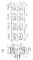
- FIG. 1 shows, a connection fitting 1 a - known per se and therefore not shown - test device for prefabricated hoses a surrounding a test equipment supply line 2 connecting piece 3 for the test apparatus and a test head 4, which is an axially adjacent to the test equipment supply line receiving space. 5 for sealingly receiving a hose fitting 6 located on a hose or tubing to be tested.
- hose fitting 6 As an example of such a hose fitting 6 are in Fig. 2a to 2d Flange components 6 shown and generally designated by the reference numeral 6 and according to their different geometric configuration additionally with the reference numerals in parentheses 6a to 6d.
- the flange components 6 can be tested successively without structural changes to the test head 4 and without additional assembly steps in the fitting according to the invention.
- seal 7 is provided, which is designed and arranged so that the flange 6 in the assembled and operating state on its outer peripheral surface 8, in turn, according to their possible different geometric design in Fig. 2a to 2d additionally denoted by the reference numerals 8a to 8d in parenthesis, sealing on the outside, as in particular Fig. 4 can be removed.
- the seal 7 is designed as an O-ring seal, which is arranged in a circumferential groove 9 in the inner peripheral surface 10 of the receiving space 5 of the test head 4.
- the receiving space 5 starting from an end face 11 of the test head 4 has an axial depth 12 which is dimensioned according to an axial height 13 of a flange 14 on the flange 6 to be accommodated in the receiving space, and in particular greater than or equal to the height of the flange 13.
- the flange 14 and its height 13 are again in Fig. 2a to 2d additionally denoted by the parenthesized reference numerals 14a to 14d and 13a to 13d.
- circumferential groove 9 is arranged starting from the end face 11 of the probe 4 in an axial depth position 15 in the first half, preferably in the first third of the depth 12 of the receiving space. 5 located.
- a present in the operating state pressure namely has the tendency to push out a plugged into the receiving space flange 6 in the axial direction X-X from the receiving space 5. This can be permitted until the flange 14 of the flange component 6 received in the receiving space 4 terminates flush with the end face 11 of the connection fitting 1 on its side facing away from the connection fitting 1.
- connection fitting 1 facing end 16 - or according to the different design 16 a to 16 c - the flange 14th of the flange 6 is arranged in the operating state, starting from the end face 11 of the probe 4 in the axial depth position 15, which is located in the second half, but at least in a second third of the axial depth 12 of the receiving space 5.
- Both flange components 6d with larger flange thickness 13d, as in the embodiment in Fig. 2d , as well as flange components 6a, 6b, 6c with a smaller flange thickness 13a, 13b, 13c, as in the embodiments in Fig. 2a to 2c , Can thus be included in the connection with the connection fitting 1 according to the invention under functionally reliable seal.
- the test head 4 of the connection fitting 1 has a head flange 17 and a head extension 18, on which the connection piece 3 is for the test apparatus.
- This allows the test head 4 two in cross-section, especially in radial section, U-shaped - separately in Fig. 3 shown - attach mounting shells 19, which include the test head 4, in particular its head flange 17 and head extension 18, positively in the assembled state.
- the mounting half shells 19 may in particular each have a projection 20 which covers the receiving space 5 at the edge. The accommodated in the receiving space 5 flange 14 of the flange 6 is thereby covered in the assembled state on its side facing away from the connection fitting 1 side by the supernatant 20 also edge and thus positively locked in the receiving space 5 against axial movement to the outside.
- the mounting half-shells 19, which can be placed on both sides in simple montage technology with the formation of two longitudinal slots 21, may - as already mentioned - advantageously be associated with an annular, for example screw-on, locking sleeve 22, the form of the mounting shells 19 and - at least in the operating state - force, preferably frictionally engaged, and thus secures the use of the mounting shells 19 formed connection between the valve 1 according to the invention and the flange 6 on the hose to be tested or on the hose to be tested.
- flange components 6a to 6d is in each case the already mentioned flange 14a to 14d on a Flanschansatz 23, which is individually designated by 23a to 23d and to which he joins each in the axial direction XX.
- the respective flange approach 23 may have different dimensions without loss of reliability and without increased assembly effort, in particular different inner and - as shown - outer diameter D23 - individually denoted by D23a to D23d - or thicknesses (not labeled).
- the in Fig. 2b illustrated embodiment 6b of the flange 6 has a significantly smaller outer diameter D23b, as the outer diameter D23a, D23c and D23d the remaining embodiments 6a, 6c, 6d of the flange 6th
- the invention is not limited to the described embodiment, but also includes all the same in the context of the invention embodiments. So it falls, for example, in the context of the invention, when the receiving space 4 of the connection fitting 1 according to the invention no round, but in adaptation to a corresponding flange 14 of the flange 6 has an oval or rectangular cross-section or the seal at a location other than the illustrated in the Area of the flange 14 of the flange 6 takes place.
Landscapes
- Physics & Mathematics (AREA)
- General Physics & Mathematics (AREA)
- Engineering & Computer Science (AREA)
- General Engineering & Computer Science (AREA)
- Mechanical Engineering (AREA)
- Health & Medical Sciences (AREA)
- Life Sciences & Earth Sciences (AREA)
- Chemical & Material Sciences (AREA)
- Analytical Chemistry (AREA)
- Biochemistry (AREA)
- General Health & Medical Sciences (AREA)
- Immunology (AREA)
- Pathology (AREA)
- Examining Or Testing Airtightness (AREA)
- Quick-Acting Or Multi-Walled Pipe Joints (AREA)
- Joints That Cut Off Fluids, And Hose Joints (AREA)
- Investigating Strength Of Materials By Application Of Mechanical Stress (AREA)
Claims (6)
- Dispositif de raccordement (1) destiné à la réalisation d'un raccordement avec un raccord pour flexible (6) d'une conduite en tuyaux flexibles, comportant une tubulure de raccordement (3), entourant une conduite d'alimentation (2), et une tête (4) qui est munie d'un collet (17) et d'une queue (18), ainsi que d'un logement (5), et dans lequel le raccord pour flexible (6) peut être raccordé de manière étanche au moyen d'un joint d'étanchéité (7), ledit joint d'étanchéité (7) étant posé dans une rainure périphérique (9) qui est située dans une surface périphérique intérieure (10) de la tête (4),
caractérisé en ce que la conduite d'alimentation (2) est réalisée sous la forme d'une conduite d'alimentation pour fluide d'essai (2) et la tête (4) est réalisée sous la forme d'une tête d'essai (4) pour un dispositif d'essai, sachant que dans le logement (5) peut être logé un élément à bride (6, 6a, 6b, 6c, 6d) en tant que raccord pour flexible (6), lequel comporte une bride (14, 14a, 14b, 14c, 14d) qui, au-delà d'une hauteur axiale (13, 13a, 13b, 13c, 13d), possède un diamètre extérieur (D14), moyennant quoi il se forme une surface périphérique extérieure (8, 8a, 8b, 8c, 8d) qui, dans la position de montage, est entourée de l'extérieur de manière étanche par le joint d'étanchéité (7), le logement (5) possédant, à partir d'une face frontale (11) de la tête d'essai (4), une profondeur axiale (12) qui est supérieure ou égale à la hauteur (13, 13a, 13b, 13c, 13d) de la bride (14, 14a, 14b, 14c, 14d), la rainure périphérique (9) étant disposée, à partir de la face frontale (11) de la tête d'essai (4), dans une position en profondeur axiale (15) qui se situe dans la première moitié de la profondeur (12) du logement (5), de telle sorte que le joint d'étanchéité (7) assure une étanchéité efficace lorsqu'une pression régnant en cours de service pousse l'élément à bride (6, 6a, 6b, 6c, 6d) hors du logement (5) dans la direction axiale (X-X), jusqu'à ce que la bride (14, 14a, 14b, 14c, 14d) de l'élément à bride (6, 6a, 6b, 6c, 6d), reçue dans le logement (5), soit située, sur son côté détourné du dispositif de raccordement (1), à fleur avec la face frontale (11) du dispositif de raccordement (1), et en ce qu'au collet (17) et à la queue (18) de la tête d'essai (4) sont associées deux demi-coquilles de fixation (19) avec une section en forme de U et faisant partie du dispositif de raccordement (1), lesquelles, dans la position de montage, entourent par conjugaison de forme le collet (17) et la queue (18) et lesquelles comportent chacune une saillie (20) qui recouvre, sur le bord sur le côté détourné du dispositif de raccordement (1), le logement (5) et la bride (14, 14a, 14b, 14c, 14d) apte à être reçue dans le logement (5), et qui bloque donc par conjugaison de forme la bride (14, 14a, 14b, 14c, 14d) dans le logement (5) contre tout mouvement axial vers l'extérieur. - Dispositif de raccordement (1) selon la revendication 1, caractérisé en ce que le joint d'étanchéité (7) est un joint torique.
- Dispositif de raccordement (1) selon la revendication 1 ou 2, caractérisé en ce qu'aux demi-coquilles de fixation (19) est associé un manchon de blocage (22) annulaire qui entoure les demi-coquilles de fixation (19) par conjugaison de forme et - au moins dans la position de service - par application de force.
- Dispositif de raccordement (1) selon la revendication 3, caractérisé en ce que le manchon de blocage (22) peut être vissé sur les demi-coquilles de fixation (19).
- Dispositif de raccordement (1) selon la revendication 3 ou 4, caractérisé en ce que le manchon de blocage (22) entoure par l'application d'une friction les demi-coquilles de fixation (19).
- Raccordement destiné à être utilisé dans un dispositif d'essai, formé par un dispositif de raccordement (1) selon l'une quelconque des revendications 1 à 5 et par un raccord pour flexible (6) pour une conduite en tuyaux flexibles.
Priority Applications (1)
| Application Number | Priority Date | Filing Date | Title |
|---|---|---|---|
| PL06124210T PL1788295T3 (pl) | 2005-11-18 | 2006-11-16 | Armatura przyłączeniowa urządzenia kontrolnego dla przewodów giętkich z armaturą wężową |
Applications Claiming Priority (1)
| Application Number | Priority Date | Filing Date | Title |
|---|---|---|---|
| DE202005018060U DE202005018060U1 (de) | 2005-11-18 | 2005-11-18 | Anschlussarmatur einer Prüfeinrichtung für mit Schlaucharmaturen konfektionierte Schlauchleitungen |
Publications (3)
| Publication Number | Publication Date |
|---|---|
| EP1788295A1 EP1788295A1 (fr) | 2007-05-23 |
| EP1788295A8 EP1788295A8 (fr) | 2007-09-26 |
| EP1788295B1 true EP1788295B1 (fr) | 2010-08-11 |
Family
ID=36062643
Family Applications (1)
| Application Number | Title | Priority Date | Filing Date |
|---|---|---|---|
| EP06124210A Not-in-force EP1788295B1 (fr) | 2005-11-18 | 2006-11-16 | Dispositif de raccordement pour raccorder un dispositif de test à un embout de tuyau flexible |
Country Status (4)
| Country | Link |
|---|---|
| EP (1) | EP1788295B1 (fr) |
| AT (1) | ATE477449T1 (fr) |
| DE (2) | DE202005018060U1 (fr) |
| PL (1) | PL1788295T3 (fr) |
Families Citing this family (2)
| Publication number | Priority date | Publication date | Assignee | Title |
|---|---|---|---|---|
| CN106482929B (zh) * | 2016-11-30 | 2018-08-28 | 南京航空航天大学 | 一种用于消减探针支杆绕流尾迹的罩型薄板结构 |
| CN115493803B (zh) * | 2022-08-26 | 2023-05-26 | 哈尔滨工程大学 | 一种可维持气密的旋转测力装置及测力方法 |
Family Cites Families (6)
| Publication number | Priority date | Publication date | Assignee | Title |
|---|---|---|---|---|
| DE3047867C2 (de) * | 1980-12-18 | 1982-09-16 | Rasmussen Gmbh, 6457 Maintal | Rohrverbindung |
| DE3444930A1 (de) * | 1984-12-08 | 1986-06-12 | Gustav 6128 Höchst Horn | Rohrgelenk fuer spuel- und kuehlfluessigkeitsleitungen an werkzeugmaschinen |
| FR2738894B1 (fr) * | 1995-09-20 | 1997-12-05 | Valeo Climatisation | Procede simplifie pour le raccordement coaxial de deux tubulures |
| US5749606A (en) | 1996-02-13 | 1998-05-12 | General Motors Corporation | Connector assembly with retainer |
| DE19814559A1 (de) * | 1997-12-04 | 1999-06-17 | Fischer Georg Rohrleitung | Rohrverbindung |
| DE10154840A1 (de) * | 2001-11-08 | 2003-05-22 | Bosch Gmbh Robert | Befestigungsvorrichtung |
-
2005
- 2005-11-18 DE DE202005018060U patent/DE202005018060U1/de not_active Expired - Lifetime
-
2006
- 2006-11-16 EP EP06124210A patent/EP1788295B1/fr not_active Not-in-force
- 2006-11-16 DE DE502006007627T patent/DE502006007627D1/de active Active
- 2006-11-16 AT AT06124210T patent/ATE477449T1/de active
- 2006-11-16 PL PL06124210T patent/PL1788295T3/pl unknown
Also Published As
| Publication number | Publication date |
|---|---|
| ATE477449T1 (de) | 2010-08-15 |
| DE202005018060U1 (de) | 2006-03-02 |
| EP1788295A1 (fr) | 2007-05-23 |
| PL1788295T3 (pl) | 2011-04-29 |
| DE502006007627D1 (de) | 2010-09-23 |
| EP1788295A8 (fr) | 2007-09-26 |
Similar Documents
| Publication | Publication Date | Title |
|---|---|---|
| DE19935246B4 (de) | Steckverbinder | |
| EP3004702B1 (fr) | Combination d'un boîtier et d'une soupape | |
| EP1319451A1 (fr) | Elément de support d'un paroi, en particulier pour le paroid d'un couvercle ou d'un récipient | |
| DE102017105505A1 (de) | Fitting zum Verbinden mit mindestens einem Rohr und Verfahren zum Herstellen einer Verbindung | |
| DE3924173C2 (fr) | ||
| DE102004044917A1 (de) | Lösbare Steckverbindung für Rohrleitungen od. dgl. | |
| EP1770320B1 (fr) | Raccord détachable à fiche pour des tuyaux | |
| DE19933256A1 (de) | Anschlussstutzen und Gehäuse, insbesondere Kraftstoffhochdruckspeicher, mit vorgespannt angeschweißtem Anschlussstutzen für ein Kraftstoffeinspritzsystem für Brennkraftmaschinen | |
| DE19914061A1 (de) | Anschlußelement für Verbundschläuche und Verfahren zum Anschließen von Verbundschläuchen | |
| EP1788295B1 (fr) | Dispositif de raccordement pour raccorder un dispositif de test à un embout de tuyau flexible | |
| EP2453157B1 (fr) | Système de raccord pour l'installation d'un appareil de conduite de l'eau | |
| DE102010054251A1 (de) | Anbindung einer Leitung | |
| WO2018210622A1 (fr) | Dispositif de raccordement | |
| DE102008050073A1 (de) | Anschluss für ein Rohr | |
| EP4083486A1 (fr) | Connecteur | |
| DE19714801C1 (de) | Elastisches Dichtelement für eine hydraulische Steckverbindung | |
| DE102004016051A1 (de) | Bremskraftverstärker | |
| EP2023027A2 (fr) | Jonction tubulaire | |
| DE10107465C1 (de) | Steckverbindung für Rohrleitungen | |
| EP2559929B1 (fr) | Traversée de conduite avec volume de contrôle | |
| EP1026432B1 (fr) | Dispositif de raccordement pour tuyaux | |
| EP1418378B1 (fr) | Element pour la fixation d'une buse à une conduite de fluide | |
| DE202009005674U1 (de) | Vorrichtung zum schwenkbaren Verbinden von zwei Leitungsabschnitten | |
| DE10064976A1 (de) | Armatur mit Anschlussadapter | |
| DE102005033665A1 (de) | Aufnahmeteil für einen Stecker |
Legal Events
| Date | Code | Title | Description |
|---|---|---|---|
| PUAI | Public reference made under article 153(3) epc to a published international application that has entered the european phase |
Free format text: ORIGINAL CODE: 0009012 |
|
| AK | Designated contracting states |
Kind code of ref document: A1 Designated state(s): AT BE BG CH CY CZ DE DK EE ES FI FR GB GR HU IE IS IT LI LT LU LV MC NL PL PT RO SE SI SK TR |
|
| AX | Request for extension of the european patent |
Extension state: AL BA HR MK YU |
|
| 17P | Request for examination filed |
Effective date: 20070831 |
|
| AKX | Designation fees paid |
Designated state(s): AT BE BG CH CY CZ DE DK EE ES FI FR GB GR HU IE IS IT LI LT LU LV MC NL PL PT RO SE SI SK TR |
|
| 17Q | First examination report despatched |
Effective date: 20080207 |
|
| GRAP | Despatch of communication of intention to grant a patent |
Free format text: ORIGINAL CODE: EPIDOSNIGR1 |
|
| GRAS | Grant fee paid |
Free format text: ORIGINAL CODE: EPIDOSNIGR3 |
|
| GRAA | (expected) grant |
Free format text: ORIGINAL CODE: 0009210 |
|
| AK | Designated contracting states |
Kind code of ref document: B1 Designated state(s): AT BE BG CH CY CZ DE DK EE ES FI FR GB GR HU IE IS IT LI LT LU LV MC NL PL PT RO SE SI SK TR |
|
| REG | Reference to a national code |
Ref country code: GB Ref legal event code: FG4D Free format text: NOT ENGLISH |
|
| REG | Reference to a national code |
Ref country code: CH Ref legal event code: EP Ref country code: CH Ref legal event code: NV Representative=s name: BRAUNPAT BRAUN EDER AG |
|
| REG | Reference to a national code |
Ref country code: IE Ref legal event code: FG4D Free format text: LANGUAGE OF EP DOCUMENT: GERMAN |
|
| REF | Corresponds to: |
Ref document number: 502006007627 Country of ref document: DE Date of ref document: 20100923 Kind code of ref document: P |
|
| REG | Reference to a national code |
Ref country code: NL Ref legal event code: VDEP Effective date: 20100811 |
|
| LTIE | Lt: invalidation of european patent or patent extension |
Effective date: 20100811 |
|
| PG25 | Lapsed in a contracting state [announced via postgrant information from national office to epo] |
Ref country code: LT Free format text: LAPSE BECAUSE OF FAILURE TO SUBMIT A TRANSLATION OF THE DESCRIPTION OR TO PAY THE FEE WITHIN THE PRESCRIBED TIME-LIMIT Effective date: 20100811 Ref country code: FI Free format text: LAPSE BECAUSE OF FAILURE TO SUBMIT A TRANSLATION OF THE DESCRIPTION OR TO PAY THE FEE WITHIN THE PRESCRIBED TIME-LIMIT Effective date: 20100811 Ref country code: NL Free format text: LAPSE BECAUSE OF FAILURE TO SUBMIT A TRANSLATION OF THE DESCRIPTION OR TO PAY THE FEE WITHIN THE PRESCRIBED TIME-LIMIT Effective date: 20100811 |
|
| PG25 | Lapsed in a contracting state [announced via postgrant information from national office to epo] |
Ref country code: BG Free format text: LAPSE BECAUSE OF FAILURE TO SUBMIT A TRANSLATION OF THE DESCRIPTION OR TO PAY THE FEE WITHIN THE PRESCRIBED TIME-LIMIT Effective date: 20101111 Ref country code: PT Free format text: LAPSE BECAUSE OF FAILURE TO SUBMIT A TRANSLATION OF THE DESCRIPTION OR TO PAY THE FEE WITHIN THE PRESCRIBED TIME-LIMIT Effective date: 20101213 Ref country code: IS Free format text: LAPSE BECAUSE OF FAILURE TO SUBMIT A TRANSLATION OF THE DESCRIPTION OR TO PAY THE FEE WITHIN THE PRESCRIBED TIME-LIMIT Effective date: 20101211 Ref country code: CY Free format text: LAPSE BECAUSE OF FAILURE TO SUBMIT A TRANSLATION OF THE DESCRIPTION OR TO PAY THE FEE WITHIN THE PRESCRIBED TIME-LIMIT Effective date: 20100811 Ref country code: SI Free format text: LAPSE BECAUSE OF FAILURE TO SUBMIT A TRANSLATION OF THE DESCRIPTION OR TO PAY THE FEE WITHIN THE PRESCRIBED TIME-LIMIT Effective date: 20100811 |
|
| REG | Reference to a national code |
Ref country code: IE Ref legal event code: FD4D |
|
| PG25 | Lapsed in a contracting state [announced via postgrant information from national office to epo] |
Ref country code: LV Free format text: LAPSE BECAUSE OF FAILURE TO SUBMIT A TRANSLATION OF THE DESCRIPTION OR TO PAY THE FEE WITHIN THE PRESCRIBED TIME-LIMIT Effective date: 20100811 Ref country code: GR Free format text: LAPSE BECAUSE OF FAILURE TO SUBMIT A TRANSLATION OF THE DESCRIPTION OR TO PAY THE FEE WITHIN THE PRESCRIBED TIME-LIMIT Effective date: 20101112 Ref country code: SE Free format text: LAPSE BECAUSE OF FAILURE TO SUBMIT A TRANSLATION OF THE DESCRIPTION OR TO PAY THE FEE WITHIN THE PRESCRIBED TIME-LIMIT Effective date: 20100811 |
|
| PG25 | Lapsed in a contracting state [announced via postgrant information from national office to epo] |
Ref country code: DK Free format text: LAPSE BECAUSE OF FAILURE TO SUBMIT A TRANSLATION OF THE DESCRIPTION OR TO PAY THE FEE WITHIN THE PRESCRIBED TIME-LIMIT Effective date: 20100811 Ref country code: IE Free format text: LAPSE BECAUSE OF FAILURE TO SUBMIT A TRANSLATION OF THE DESCRIPTION OR TO PAY THE FEE WITHIN THE PRESCRIBED TIME-LIMIT Effective date: 20100811 |
|
| REG | Reference to a national code |
Ref country code: PL Ref legal event code: T3 |
|
| PG25 | Lapsed in a contracting state [announced via postgrant information from national office to epo] |
Ref country code: RO Free format text: LAPSE BECAUSE OF FAILURE TO SUBMIT A TRANSLATION OF THE DESCRIPTION OR TO PAY THE FEE WITHIN THE PRESCRIBED TIME-LIMIT Effective date: 20100811 Ref country code: SK Free format text: LAPSE BECAUSE OF FAILURE TO SUBMIT A TRANSLATION OF THE DESCRIPTION OR TO PAY THE FEE WITHIN THE PRESCRIBED TIME-LIMIT Effective date: 20100811 Ref country code: CZ Free format text: LAPSE BECAUSE OF FAILURE TO SUBMIT A TRANSLATION OF THE DESCRIPTION OR TO PAY THE FEE WITHIN THE PRESCRIBED TIME-LIMIT Effective date: 20100811 Ref country code: EE Free format text: LAPSE BECAUSE OF FAILURE TO SUBMIT A TRANSLATION OF THE DESCRIPTION OR TO PAY THE FEE WITHIN THE PRESCRIBED TIME-LIMIT Effective date: 20100811 |
|
| PLBE | No opposition filed within time limit |
Free format text: ORIGINAL CODE: 0009261 |
|
| STAA | Information on the status of an ep patent application or granted ep patent |
Free format text: STATUS: NO OPPOSITION FILED WITHIN TIME LIMIT |
|
| PG25 | Lapsed in a contracting state [announced via postgrant information from national office to epo] |
Ref country code: ES Free format text: LAPSE BECAUSE OF FAILURE TO SUBMIT A TRANSLATION OF THE DESCRIPTION OR TO PAY THE FEE WITHIN THE PRESCRIBED TIME-LIMIT Effective date: 20101122 Ref country code: MC Free format text: LAPSE BECAUSE OF NON-PAYMENT OF DUE FEES Effective date: 20101130 |
|
| 26N | No opposition filed |
Effective date: 20110512 |
|
| REG | Reference to a national code |
Ref country code: DE Ref legal event code: R097 Ref document number: 502006007627 Country of ref document: DE Effective date: 20110512 |
|
| PG25 | Lapsed in a contracting state [announced via postgrant information from national office to epo] |
Ref country code: HU Free format text: LAPSE BECAUSE OF FAILURE TO SUBMIT A TRANSLATION OF THE DESCRIPTION OR TO PAY THE FEE WITHIN THE PRESCRIBED TIME-LIMIT Effective date: 20110212 Ref country code: LU Free format text: LAPSE BECAUSE OF NON-PAYMENT OF DUE FEES Effective date: 20101116 |
|
| PG25 | Lapsed in a contracting state [announced via postgrant information from national office to epo] |
Ref country code: TR Free format text: LAPSE BECAUSE OF FAILURE TO SUBMIT A TRANSLATION OF THE DESCRIPTION OR TO PAY THE FEE WITHIN THE PRESCRIBED TIME-LIMIT Effective date: 20100811 |
|
| PGFP | Annual fee paid to national office [announced via postgrant information from national office to epo] |
Ref country code: FR Payment date: 20131108 Year of fee payment: 8 Ref country code: GB Payment date: 20131113 Year of fee payment: 8 Ref country code: CH Payment date: 20131112 Year of fee payment: 8 Ref country code: AT Payment date: 20131028 Year of fee payment: 8 |
|
| PGFP | Annual fee paid to national office [announced via postgrant information from national office to epo] |
Ref country code: PL Payment date: 20131112 Year of fee payment: 8 Ref country code: BE Payment date: 20131113 Year of fee payment: 8 Ref country code: IT Payment date: 20131106 Year of fee payment: 8 |
|
| PGFP | Annual fee paid to national office [announced via postgrant information from national office to epo] |
Ref country code: DE Payment date: 20140128 Year of fee payment: 8 |
|
| REG | Reference to a national code |
Ref country code: DE Ref legal event code: R119 Ref document number: 502006007627 Country of ref document: DE |
|
| PG25 | Lapsed in a contracting state [announced via postgrant information from national office to epo] |
Ref country code: BE Free format text: LAPSE BECAUSE OF NON-PAYMENT OF DUE FEES Effective date: 20141130 |
|
| REG | Reference to a national code |
Ref country code: CH Ref legal event code: PL |
|
| REG | Reference to a national code |
Ref country code: AT Ref legal event code: MM01 Ref document number: 477449 Country of ref document: AT Kind code of ref document: T Effective date: 20141116 |
|
| GBPC | Gb: european patent ceased through non-payment of renewal fee |
Effective date: 20141116 |
|
| PG25 | Lapsed in a contracting state [announced via postgrant information from national office to epo] |
Ref country code: CH Free format text: LAPSE BECAUSE OF NON-PAYMENT OF DUE FEES Effective date: 20141130 Ref country code: LI Free format text: LAPSE BECAUSE OF NON-PAYMENT OF DUE FEES Effective date: 20141130 |
|
| REG | Reference to a national code |
Ref country code: FR Ref legal event code: ST Effective date: 20150731 |
|
| PG25 | Lapsed in a contracting state [announced via postgrant information from national office to epo] |
Ref country code: AT Free format text: LAPSE BECAUSE OF NON-PAYMENT OF DUE FEES Effective date: 20141116 |
|
| PG25 | Lapsed in a contracting state [announced via postgrant information from national office to epo] |
Ref country code: GB Free format text: LAPSE BECAUSE OF NON-PAYMENT OF DUE FEES Effective date: 20141116 Ref country code: DE Free format text: LAPSE BECAUSE OF NON-PAYMENT OF DUE FEES Effective date: 20150602 |
|
| PG25 | Lapsed in a contracting state [announced via postgrant information from national office to epo] |
Ref country code: FR Free format text: LAPSE BECAUSE OF NON-PAYMENT OF DUE FEES Effective date: 20141201 |
|
| PG25 | Lapsed in a contracting state [announced via postgrant information from national office to epo] |
Ref country code: IT Free format text: LAPSE BECAUSE OF NON-PAYMENT OF DUE FEES Effective date: 20141116 |
|
| PG25 | Lapsed in a contracting state [announced via postgrant information from national office to epo] |
Ref country code: PL Free format text: LAPSE BECAUSE OF NON-PAYMENT OF DUE FEES Effective date: 20141116 |