EP1788295B1 - Connection fitting for connecting a testing device to a hose fitting of a flexible conduit - Google Patents
Connection fitting for connecting a testing device to a hose fitting of a flexible conduit Download PDFInfo
- Publication number
- EP1788295B1 EP1788295B1 EP06124210A EP06124210A EP1788295B1 EP 1788295 B1 EP1788295 B1 EP 1788295B1 EP 06124210 A EP06124210 A EP 06124210A EP 06124210 A EP06124210 A EP 06124210A EP 1788295 B1 EP1788295 B1 EP 1788295B1
- Authority
- EP
- European Patent Office
- Prior art keywords
- flange
- head
- fitting
- receiving space
- connection fitting
- Prior art date
- Legal status (The legal status is an assumption and is not a legal conclusion. Google has not performed a legal analysis and makes no representation as to the accuracy of the status listed.)
- Not-in-force
Links
Images

Classifications
-
- G—PHYSICS
- G01—MEASURING; TESTING
- G01M—TESTING STATIC OR DYNAMIC BALANCE OF MACHINES OR STRUCTURES; TESTING OF STRUCTURES OR APPARATUS, NOT OTHERWISE PROVIDED FOR
- G01M3/00—Investigating fluid-tightness of structures
- G01M3/02—Investigating fluid-tightness of structures by using fluid or vacuum
- G01M3/022—Test plugs for closing off the end of a pipe
-
- F—MECHANICAL ENGINEERING; LIGHTING; HEATING; WEAPONS; BLASTING
- F16—ENGINEERING ELEMENTS AND UNITS; GENERAL MEASURES FOR PRODUCING AND MAINTAINING EFFECTIVE FUNCTIONING OF MACHINES OR INSTALLATIONS; THERMAL INSULATION IN GENERAL
- F16L—PIPES; JOINTS OR FITTINGS FOR PIPES; SUPPORTS FOR PIPES, CABLES OR PROTECTIVE TUBING; MEANS FOR THERMAL INSULATION IN GENERAL
- F16L33/00—Arrangements for connecting hoses to rigid members; Rigid hose connectors, i.e. single members engaging both hoses
- F16L33/28—Arrangements for connecting hoses to rigid members; Rigid hose connectors, i.e. single members engaging both hoses for hoses with one end terminating in a radial flange or collar
-
- G—PHYSICS
- G01—MEASURING; TESTING
- G01N—INVESTIGATING OR ANALYSING MATERIALS BY DETERMINING THEIR CHEMICAL OR PHYSICAL PROPERTIES
- G01N3/00—Investigating strength properties of solid materials by application of mechanical stress
- G01N3/02—Details
- G01N3/04—Chucks
-
- F—MECHANICAL ENGINEERING; LIGHTING; HEATING; WEAPONS; BLASTING
- F16—ENGINEERING ELEMENTS AND UNITS; GENERAL MEASURES FOR PRODUCING AND MAINTAINING EFFECTIVE FUNCTIONING OF MACHINES OR INSTALLATIONS; THERMAL INSULATION IN GENERAL
- F16L—PIPES; JOINTS OR FITTINGS FOR PIPES; SUPPORTS FOR PIPES, CABLES OR PROTECTIVE TUBING; MEANS FOR THERMAL INSULATION IN GENERAL
- F16L2201/00—Special arrangements for pipe couplings
- F16L2201/30—Detecting leaks
-
- G—PHYSICS
- G01—MEASURING; TESTING
- G01N—INVESTIGATING OR ANALYSING MATERIALS BY DETERMINING THEIR CHEMICAL OR PHYSICAL PROPERTIES
- G01N2203/00—Investigating strength properties of solid materials by application of mechanical stress
- G01N2203/02—Details not specific for a particular testing method
- G01N2203/026—Specifications of the specimen
- G01N2203/0262—Shape of the specimen
- G01N2203/0274—Tubular or ring-shaped specimens
Definitions
- connection fitting for hose fittings in particular with flange components, prefabricated hose assemblies according to the preamble of claim 1 and a connection for use in a test device, consisting of such a connection fitting and hose fitting, according to the preamble of claim 6.
- Hoses and hose lines are used, inter alia, in hydraulic systems of various industrial sectors.
- the manufacturers are striving to collect data on safety-relevant properties, failure and aging behavior as well as behavior against environmental influences.
- safety-relevant properties for example, in the standards “rubber and plastic hoses and hose assemblies - hydrostatic testing” (ISO 1402: 2001) and “hoses and hose assemblies, tests” (DIN 20024) requirements for compressive strength, including high-pressure pipes, are specified meanwhile, the international standards of ISO / TC 45 have been incorporated into the German Standards and are binding in the latter standard.
- connection fittings of the type mentioned are known, the z. B. in pressure test benches use and allow it to be tested a hose or a hose to be tested - together with a hose fitting located thereon, in particular a flange - to connect to the appropriate tester and then pressurized with the test equipment under the intended pressure.
- a pressure medium line comprehensive flange components which may in particular have a flange and an axially adjacent thereto flange, different dimensions, eg. B. different inner and outer diameter of the Flanschansatzes or thicknesses and inner and outer diameter of the flange.
- the document refers to a connector assembly for fluid-carrying lines in motor vehicles.
- a specially designed head part which is a spigot and having a straight portion with a free end and a radially outwardly extending conical portion
- a supply line female member bore "
- an O-ring may be arranged, the effect of which, however, can be reduced or eliminated altogether by the tendency of an operating pressure to slide the inserted head part out of the supply line in the axial direction.
- the present invention is based on the object to improve a connection fitting and a compound of the type mentioned in such a way that it ensures unimpeded functional performance universal use for testing equipped with hose fittings piping and thereby a small time required for pressure test,
- connection fitting according to claim 1 and with a compound according to claim 6.
- the invention achieves a high pressure tightness of the connection according to the invention, which consists of the connection fitting according to the invention and of the hose or hose line to be tested with the hose fitting
- the invention makes it possible to provide a test head of the test device which Universal test head can be called, because one and the same head in a variety of flange with different geometric dimensions, such as inner and outer diameter of the Flanschansatzes or thickness and inner and outer diameter of the flange, can be used. This eliminates all assembly work, as they were known to retrofit a test bench for a hose with new, other flange component were necessary.
- the seal for.
- the test head preferably two in cross-section U-shaped mounting shells be assigned, which include the test head and the flange located thereon fitting the fitting in the assembled state, in turn, the mounting shells an annular, For example, screw-on, locking sleeve is associated with the form-fitting and - at least in the operating state - force, preferably frictionally engaged, the mounting shells.
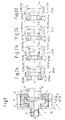
- FIG. 1 shows, a connection fitting 1 a - known per se and therefore not shown - test device for prefabricated hoses a surrounding a test equipment supply line 2 connecting piece 3 for the test apparatus and a test head 4, which is an axially adjacent to the test equipment supply line receiving space. 5 for sealingly receiving a hose fitting 6 located on a hose or tubing to be tested.
- hose fitting 6 As an example of such a hose fitting 6 are in Fig. 2a to 2d Flange components 6 shown and generally designated by the reference numeral 6 and according to their different geometric configuration additionally with the reference numerals in parentheses 6a to 6d.
- the flange components 6 can be tested successively without structural changes to the test head 4 and without additional assembly steps in the fitting according to the invention.
- seal 7 is provided, which is designed and arranged so that the flange 6 in the assembled and operating state on its outer peripheral surface 8, in turn, according to their possible different geometric design in Fig. 2a to 2d additionally denoted by the reference numerals 8a to 8d in parenthesis, sealing on the outside, as in particular Fig. 4 can be removed.
- the seal 7 is designed as an O-ring seal, which is arranged in a circumferential groove 9 in the inner peripheral surface 10 of the receiving space 5 of the test head 4.
- the receiving space 5 starting from an end face 11 of the test head 4 has an axial depth 12 which is dimensioned according to an axial height 13 of a flange 14 on the flange 6 to be accommodated in the receiving space, and in particular greater than or equal to the height of the flange 13.
- the flange 14 and its height 13 are again in Fig. 2a to 2d additionally denoted by the parenthesized reference numerals 14a to 14d and 13a to 13d.
- circumferential groove 9 is arranged starting from the end face 11 of the probe 4 in an axial depth position 15 in the first half, preferably in the first third of the depth 12 of the receiving space. 5 located.
- a present in the operating state pressure namely has the tendency to push out a plugged into the receiving space flange 6 in the axial direction X-X from the receiving space 5. This can be permitted until the flange 14 of the flange component 6 received in the receiving space 4 terminates flush with the end face 11 of the connection fitting 1 on its side facing away from the connection fitting 1.
- connection fitting 1 facing end 16 - or according to the different design 16 a to 16 c - the flange 14th of the flange 6 is arranged in the operating state, starting from the end face 11 of the probe 4 in the axial depth position 15, which is located in the second half, but at least in a second third of the axial depth 12 of the receiving space 5.
- Both flange components 6d with larger flange thickness 13d, as in the embodiment in Fig. 2d , as well as flange components 6a, 6b, 6c with a smaller flange thickness 13a, 13b, 13c, as in the embodiments in Fig. 2a to 2c , Can thus be included in the connection with the connection fitting 1 according to the invention under functionally reliable seal.
- the test head 4 of the connection fitting 1 has a head flange 17 and a head extension 18, on which the connection piece 3 is for the test apparatus.
- This allows the test head 4 two in cross-section, especially in radial section, U-shaped - separately in Fig. 3 shown - attach mounting shells 19, which include the test head 4, in particular its head flange 17 and head extension 18, positively in the assembled state.
- the mounting half shells 19 may in particular each have a projection 20 which covers the receiving space 5 at the edge. The accommodated in the receiving space 5 flange 14 of the flange 6 is thereby covered in the assembled state on its side facing away from the connection fitting 1 side by the supernatant 20 also edge and thus positively locked in the receiving space 5 against axial movement to the outside.
- the mounting half-shells 19, which can be placed on both sides in simple montage technology with the formation of two longitudinal slots 21, may - as already mentioned - advantageously be associated with an annular, for example screw-on, locking sleeve 22, the form of the mounting shells 19 and - at least in the operating state - force, preferably frictionally engaged, and thus secures the use of the mounting shells 19 formed connection between the valve 1 according to the invention and the flange 6 on the hose to be tested or on the hose to be tested.
- flange components 6a to 6d is in each case the already mentioned flange 14a to 14d on a Flanschansatz 23, which is individually designated by 23a to 23d and to which he joins each in the axial direction XX.
- the respective flange approach 23 may have different dimensions without loss of reliability and without increased assembly effort, in particular different inner and - as shown - outer diameter D23 - individually denoted by D23a to D23d - or thicknesses (not labeled).
- the in Fig. 2b illustrated embodiment 6b of the flange 6 has a significantly smaller outer diameter D23b, as the outer diameter D23a, D23c and D23d the remaining embodiments 6a, 6c, 6d of the flange 6th
- the invention is not limited to the described embodiment, but also includes all the same in the context of the invention embodiments. So it falls, for example, in the context of the invention, when the receiving space 4 of the connection fitting 1 according to the invention no round, but in adaptation to a corresponding flange 14 of the flange 6 has an oval or rectangular cross-section or the seal at a location other than the illustrated in the Area of the flange 14 of the flange 6 takes place.
Abstract
Description
Die vorliegende Erfindung betrifft eine Anschlussarmatur für mit Schlaucharmaturen, insbesondere mit Flanschbauteilen, konfektionierte Schlauchleitungen nach dem Oberbegriff des Anspruchs 1 und eine Verbindung zur Verwendung in einer Prüfvorrichtung, bestehend aus einer derartigen Anschlussarmatur und aus Schlaucharmatur, nach dem Oberbegriff des Anspruchs 6.The present invention relates to a connection fitting for hose fittings, in particular with flange components, prefabricated hose assemblies according to the preamble of
Schläuche und Schlauchleitungen, insbesondere Hydraulikschlauchleitungen, werden unter anderem in hydraulischen Anlagen verschiedener Industriebereiche eingesetzt. Um für den vorgesehenen Einsatz eine Zuverlässige sicherheitstechnische Beurteilungs- und Vergleichsbasis zu schaffen, sind die Hersteller gehaiten, zu sicherheitsrelevanten Eigenschaften, dem Ausfall- und Alterungsverhalten sowie zum Verhalten gegenüber Umgebungseinflüssen geeignete Daten zu erheben. So sind insbesondere in den Normen "Gummi- und Kunststoffschläuche und -schlauchleitungen - Hydrostatische Prüfung" (ISO 1402:2001) und "Schläuche und Schlauchleitungen, Prüfungen" (DIN 20024) Anforderungen an die Druckbelastbarkeit, u. a. von Hochdruckleitungen, festgelegt, wobei für die in der letztgenannten Norm aufgeführten Prüfverfahren inzwischen die internationalen Normen des ISO/TC 45 in das Deutsche Normenwerk übernommen wurden und verbindlich sind.Hoses and hose lines, in particular hydraulic hose lines, are used, inter alia, in hydraulic systems of various industrial sectors. In order to create a reliable safety assessment and comparison basis for the intended use, the manufacturers are striving to collect data on safety-relevant properties, failure and aging behavior as well as behavior against environmental influences. For example, in the standards "rubber and plastic hoses and hose assemblies - hydrostatic testing" (ISO 1402: 2001) and "hoses and hose assemblies, tests" (DIN 20024) requirements for compressive strength, including high-pressure pipes, are specified meanwhile, the international standards of ISO / TC 45 have been incorporated into the German Standards and are binding in the latter standard.
Hierbei sind Anschlussarmaturen der eingangs genannten Art bekannt, die z. B. in Druck-Prüfbänken Verwendung finden und es gestatten, einen zu prüfenden Schlauch oder eine zu prüfende Schlauchleitung - mitsamt einer daran befindlichen Schlaucharmatur, insbesondere eines Flanschbauteils - an die entsprechende Prüfvorrichtung anzuschließen und danach mit dem Prüfmittel unter dem vorgesehenen Druck zu beaufschlagen. Je nach Verwendungszweck der Leitungen besitzen die entsprechenden, eine Druckmittelleitung umfassenden Flanschbauteile, die insbesondere einen Flanschansatz und einen sich daran axial anschließenden Flansch aufweisen können, unterschiedliche Abmessungen, z. B. unterschiedliche Innen- und Außendurchmesser des Flanschansatzes oder Dicken sowie Innen- und Außendurchmesser des Flansches. Dieser Tatsache Rechnung tragend sind in den bekannten Armaturen eine Vielzahl von gegeneinander auswechselbaren Prüfköpfe gebräuchlich, die in Anpassung an die Geometrie des jeweiligen Flanschbauteiles an der zu prüfenden Leitung ausgelegt sind, wobei in der Verbindung Anschlussarmatur/Flanschbauteil eine innenabdichtung, d. h. die Anordnung einer Dichtung im Inneren der Druckmittelleitung des Flanschbauteiles erfolgt. Mit der Verwendung der auswechselbaren Prüfköpfe ist sowohl ein hoher apparativer, als such montagetechnischer, d. h. die Rüstzeiten der Prüfbänke negativ beeinflussender, Aufwand verbunden.Here, connection fittings of the type mentioned are known, the z. B. in pressure test benches use and allow it to be tested a hose or a hose to be tested - together with a hose fitting located thereon, in particular a flange - to connect to the appropriate tester and then pressurized with the test equipment under the intended pressure. Depending on the intended use of the lines have the corresponding, a pressure medium line comprehensive flange components, which may in particular have a flange and an axially adjacent thereto flange, different dimensions, eg. B. different inner and outer diameter of the Flanschansatzes or thicknesses and inner and outer diameter of the flange. Taking into account this fact, in the known fittings a multiplicity of interchangeable probes are used, which are designed to adapt to the geometry of the respective flange component on the line to be tested, wherein in the connection connection fitting / flange component an inner seal, d. H. the arrangement of a seal in the interior of the pressure medium line of the flange takes place. With the use of interchangeable probes is both a high-technical, and montage technical, d. H. the setup times of the test benches negatively influencing, effort connected.
Aus der
Der vorliegenden Erfindung liegt die Aufgabe zu Grunde, eine Anschlussarmatur und eine Verbindung der eingangs genannten Art derart zu verbessern, dass sie bei unbeeinträchtigter Funktionserfüllung einen universellen Einsatz zur Prüfung von mit Schlaucharmaturen ausgestatteten Rohrleitungen und dabei eine geringe zur Druckprüfung notwendige Zeit gewährleistet,The present invention is based on the object to improve a connection fitting and a compound of the type mentioned in such a way that it ensures unimpeded functional performance universal use for testing equipped with hose fittings piping and thereby a small time required for pressure test,
Diese Aufgabe wird mit einer Anschlussarmatur gemäß dem Anspruch 1 und mit einer Verbindung gemäß dem Anspruch 6 gelöst.This object is achieved with a connection fitting according to
Durch die Erfindung wird einerseits eine hohe Druckdichtheit der erfindungsgemäßen Verbindung, die aus der erfindungsgemäßen Anschlussanmatur und aus dem zu prüfenden Schlauch oder der zu prüfenden Schlauchleitung mit der Schlaucharmatur besteht, erreicht, andererseits gestattet es die Erfindung, einen Prüfkopf der Prüfvorrichtung zu schaffen, der als Universal-Prüfkopf bezeichnet werden kann, weil ein und derselbe Kopf bei einer Vielzahl von Flanschbauteilen mit unterschiedlichen geometrischen Abmessungen, wie Innen- und Außendurchmesser des Flanschansatzes oder Dicke sowie Innen- und Außendurchmesser des Flansches, einsetzbar ist. Damit entfallen sämtliche Montagearbeiten, wie sie bekanntermaßen zur Umrüstung einer Prüfbank für eine Schlauchleitung mit neuem, anderem Flanschbauteil notwendig waren.On the one hand, the invention achieves a high pressure tightness of the connection according to the invention, which consists of the connection fitting according to the invention and of the hose or hose line to be tested with the hose fitting, on the other hand the invention makes it possible to provide a test head of the test device which Universal test head can be called, because one and the same head in a variety of flange with different geometric dimensions, such as inner and outer diameter of the Flanschansatzes or thickness and inner and outer diameter of the flange, can be used. This eliminates all assembly work, as they were known to retrofit a test bench for a hose with new, other flange component were necessary.
In bevorzugter Ausführung kann dabei insbesondere vorgesehen sein, dass die Dichtung, z. B. ein elastisch deformierbarer klassischer O-Ring mit geeigneter Schnurstärke und Shore-Härte, in einer Umfangsnut in der inneren Umfangsfläche des Aufnahmeraumes des Prüfkopfes angeordnet ist. Dies gestattet bei leichter Einsteckbarkeit des zu prüfenden Objekts eine wirksame Abdichtung - auch bei einem Außendurchmesser des Flansches, der toleranz- oder normbedingt von dem des vorhergehend geprüften Objekts abweicht. Dabei ist wegen der einfachen Zugänglichkeit auch eine leichte Auswechselbarkeit für die Dichtung gegeben.In a preferred embodiment, it may be provided in particular that the seal, for. As an elastically deformable classic O-ring with appropriate thickness and Shore hardness, is arranged in a circumferential groove in the inner peripheral surface of the receiving space of the probe. This allows for easy insertion of the object to be tested an effective seal - even with an outer diameter of the flange, which differs due to tolerances or standards of that of the previously tested object. It is given because of the easy accessibility and easy interchangeability of the seal.
Zur sicheren, aber apparativ wenig aufwändigen Halterung der Schlaucharmatur einer zu prüfenden Leitung können dem Prüfkopf bevorzugt zwei im Querschnitt U-förmige Befestigungshalbschalen zugeordnet sein, die im Montagezustand den Prüfkopf und den daran befindlichen Flanschansatz der Armatur formschlüssig umfassen, wobei wiederum den Befestigungshalbschalen eine ringförmige, beispielsweise aufschraubbare, Arretierhülse zugeordnet ist, die die Befestigungshalbschalen form- und - zumindest im Betriebszustand - kraft-, vorzugsweise reibschlüssig, umfasst.For safe, but less complex apparatus mounting the hose fitting a line to be tested, the test head preferably two in cross-section U-shaped mounting shells be assigned, which include the test head and the flange located thereon fitting the fitting in the assembled state, in turn, the mounting shells an annular, For example, screw-on, locking sleeve is associated with the form-fitting and - at least in the operating state - force, preferably frictionally engaged, the mounting shells.
Weitere vorteilhafte Ausführungen der Erfindung sind in den Unteransprüchen und der nachfolgenden speziellen Beschreibung enthalten.Further advantageous embodiments of the invention are contained in the subclaims and the following specific description.
Anhand des in den Zeichnungen dargestellten Ausführungsbeispiels wird die Erfindung näher erläutert. Es zeigen:
- Fig. 1
- einen axialen Schnitt durch eine erfindungsgemäße Anschlussarmatur einer Prüfvorrichtung für Schläuche und Schlauchleitungen,
- Fig. 2a bis 2d
- ebenfalls axial geschnitten, unterschiedliche Ausführungen von Flanschbauteilen, die sich an einem zu prüfenden Schlauch oder einer zu prüfenden Schlauchleitung befinden können und in gleichartiger Weise mit der erfindungsgemäßen Anschlussarmatur gemäß
Fig. 1 verbindbar sind, - Fig. 3
- in einer Ansicht aus radialer Richtung, vergrößert gegenüber
Fig. 1 , zwei erfindungsgemäß dem Prüfkopf bevorzugt zugeordnete Befestigungshalbschalen, - Fig. 4
- einen axialen Schnitt durch eine Verbindung einer erfindungsgemäßen Anschlussarmatur und einer zu prüfenden Schlauchleitung.
- Fig. 1
- an axial section through an inventive connection fitting a tester for hoses and hose lines,
- Fig. 2a to 2d
- also cut axially, different versions of flange components, which may be located on a hose to be tested or a hose to be tested and in a similar manner with the connection fitting according to the invention according to
Fig. 1 are connectable, - Fig. 3
- in a view from the radial direction, enlarged opposite
Fig. 1 two attachment halves preferably associated with the test head according to the invention, - Fig. 4
- an axial section through a connection of a connection fitting according to the invention and a hose to be tested.
In den Zeichnungsfiguren sind gleiche und einander entsprechende Teile stets mit den gleichen Bezugszeichen versehen, so dass sie in der Regel auch nur einmal beschrieben werden.In the drawing figures, the same and corresponding parts are always provided with the same reference numerals, so that they are usually described only once.
Wie aus
Als Beispiel für eine derartige Schlaucharmatur 6 sind in
Zur abgedichteten Aufnahme des Flanschbauteils 6 ist eine - jeweils in
Bevorzugt ist die Dichtung 7 dabei als eine O-Ring-Dichtung ausgeführt, die in einer Umfangsnut 9 in der inneren Umfangsfläche 10 des Aufnahmeraumes 5 des Prüfkopfes 4 angeordnet ist.Preferably, the seal 7 is designed as an O-ring seal, which is arranged in a
Aus
Hierzu ist es - insbesondere für kleinere Flanschhöhen 13 - von Vorteil, wenn die Umfangsnut 9 ausgehend von der Stirnseite 11 des Prüfkopfes 4 in einer axialen Tiefenposition 15 angeordnet ist, die sich in der ersten Hälfte, vorzugsweise im ersten Drittel der Tiefe 12 des Aufnahmeraumes 5 befindet.For this purpose - especially for smaller flange heights 13 - is advantageous if the
Ein im Betriebszustand vorliegender Druck hat nämlich das Bestreben, ein in den Aufnahmeraum eingestecktes Flanschbauteil 6 in axialer Richtung X-X aus dem Aufnahmeraum 5 herauszuschieben. Dies kann soweit zugelassen werden, bis der im Aufnahmeraum 4 aufgenommene Flansch 14 des Flanschbauteils 6 auf seiner der Anschlussarmatur 1 abgewandten Seite bündig mit der Stirnseite 11 der Anschlussarmatur 1 abschließt. Auch bei vorhandener geringer Höhe 13 des Flansches 14 bewirkt dann die Dichtung 7 bei der entsprechenden Tiefenposition 15 der Umfangsnut 9 eine wirksame Abdichtung der Verbindung, wobei eine der Anschlussarmatur 1 zugewandte Stirnseite 16 - bzw. entsprechend der unterschiedlichen Ausführung 16a bis 16c - des Flansches 14 des Flanschbauteils 6 im Betriebszustand ausgehend von der Stirnseite 11 des Prüfkopfes 4 in der axialen Tiefenposition 15 angeordnet ist, die sich in der zweiten Hälfte, zumindest aber in einem zweiten Drittel der axialen Tiefe 12 des Aufnahmeraumes 5 befindet.A present in the operating state pressure namely has the tendency to push out a plugged into the
Sowohl Flanschbauteile 6d mit größerer Flanschdicke 13d, wie bei der Ausführung in
Hierbei ist es - wenngleich gewisse Toleranzen durch die Wahl einer entsprechenden Schnurstärke der Dichtung 7 ausgeglichen werden können - im Sinne der Ausbildung einer hochdruckdichten Verbindung von Vorteil, wenn der Flansch 14 des Flanschbauteils 6 im Montagezustand - im Querschnitt gesehen - formschlüssig in den Aufnahmeraum 5 des Prüfkopfes 4 eingepaßt ist, was beispielsweise durch einen entsprechenden Innendurchmesser D5 des Aufnahmeraumes 5 und entsprechende Außendurchmesser D14 des Flansches 14 zum Ausdruck kommen kann.Here it is - although certain tolerances can be compensated by the choice of a corresponding thickness of the seal 7 - in the sense of forming a high-pressure-tight connection advantageous if the
Wie zeichnerisch in
Den Befestigungshalbschalen 19, die in montagetechnisch einfacher Weise unter Ausbildung zweier Längsschlitze 21 auf den Prüfkopf 4 beidseitig aufgelegt werden können, kann - wie bereits erwähnt - mit Vorteil eine ringförmige, beispielsweise aufschraubbare, Arretierhülse 22 zugeordnet sein, die die Befestigungshalbschalen 19 form- und - zumindest im Betriebszustand - kraft-, vorzugsweise reibschlüssig, umfasst und damit die unter Verwendung der Befestigungshalbschalen 19 ausgebildete Verbindung zwischen der erfindungsgemäßen Armatur 1 und dem Flanschbauteil 6 an dem zu prüfenden Schlauch bzw. an der zu prüfenden Schlauchleitung sichert.The mounting half-
Bei den in
Die Erfindung beschränkt sich nicht auf das beschriebene Ausführungsbeispiel, sondern umfasst auch alle im Sinne der Erfindung gleichwirkenden Ausführungen. So fällt es beispielsweise auch in den Rahmen der Erfindung, wenn der Aufnahmeraum 4 der erfindungsgemäßen Anschlussarmatur 1 keinen runden, sondern in Anpassung an einen entsprechenden Flansch 14 des Flanschbauteils 6 einen ovalen oder rechteckigen Querschnitt aufweist oder die Abdichtung an einer anderen als der dargestellten Stelle im Bereich des Flansches 14 des Flanschbauteiles 6 erfolgt.The invention is not limited to the described embodiment, but also includes all the same in the context of the invention embodiments. So it falls, for example, in the context of the invention, when the receiving space 4 of the connection fitting 1 according to the invention no round, but in adaptation to a corresponding
- 11
- AnschlussarmaturEnd fittings
- 22
- Prüfmittel-Zuleitung von 1Test equipment supply line of 1
- 33
- Anschlussstutzen um 2 an 4Connection piece by 2 to 4
- 44
- Prüfkopf von 1 an 3Test head from 1 to 3
- 55
- Aufnahmeraum in 4 für 6Recording room in 4 for 6
- 66
- Schlaucharmatur, Flanschbauteil - individuell 6a bis 6dHose fitting, flange component - individually 6a to 6d
- 77
- Dichtungpoetry
- 88th
- Umfangsfläche von 6 (14) - individuell 8a bis 8dCircumferential area of 6 (14) - individually 8a to 8d
- 99
- Umfangsnut in 10Circumferential groove in 10th
- 1010
- Umfangsfläche von 5Circumferential area of 5
- 1111
- Stirnseite von 4Front side of 4
- 1212
- axiale Tiefe von 5, ausgehend von 11axial depth of 5, starting from 11
- 1313
- axiale Höhe von 14 - individuell 13a bis 13daxial height of 14 - individually 13a to 13d
- 1414
- Flansch von 6 an 23 - individuell 14a bis 14dFlange from 6 to 23 - individually 14a to 14d
- 1515
- axiale Tiefenposition von 9 bzw. 16axial depth position of 9 and 16 respectively
- 1616
- Stirnseite von 6 - individuell 16a bis 16dFront side of 6 - individually 16a to 16d
- 1717
- Kopfflansch von 4Head flange of 4
- 1818
- Kopfansatz von 4Head of 4
- 1919
- BefestigungshalbschaleMounting half shell
- 2020
- Überstand von 19 über 5Supernatant from 19 over 5
- 2121
- Längsschlitzlongitudinal slot
- 2222
- Arretierhülse um 19Locking sleeve at 19
- 2323
- Flanschansatz von 6 an 14 - individuell 23a bis 23dFlange attachment from 6 to 14 - individually 23a to 23d
- D5D5
- Innendurchmesser von 5Inner diameter of 5
- D14D14
- Außendurchmesser von 14Outer diameter of 14
- D23D23
- Außendurchmesser von 23 - individuell D23a bis D23bOuter diameter of 23 - individually D23a to D23b
- X-XX X
- Längsachse von 1 (und 6)Longitudinal axis of 1 (and 6)
Claims (6)
- A connection fitting (1) for the production of a connection with a hose fitting (6) of a hose line, with a connecting branch (3) surrounding a feed line (2) and a head (4) which has a head flange (17) and a head projection (18) and also a receiving space (5) and in which the hose fitting (6) can be connected in sealed manner by means of a seal (7), the seal (7) being arranged in a peripheral groove (9) which is located in an inner peripheral surface (10) of the head (4),
characterised in that the feed line (2) is designed as a test-medium feed line (2) and the head as a test head (4) for a test device, with a flange component (6, 6a, 6b, 6c, 6d) being able to be received as hose fitting (6) in the receiving space (5), which component has a flange (14, 14a, 14b, 14c, 14d) which over an axial height (13, 13a, 13b, 13c, 13d) has an external diameter (D14) by means of which an external peripheral surface (8, 8a, 8b, 8c, 8d) is formed which in the assembled state is surrounded on the outside in sealing manner by the seal (7), the receiving space (5), starting from an end face (11) of the test head (4), having an axial depth (12) which is greater than or equal to the height (13, 13a, 13b, 13c, 13d) of the flange (14, 14a, 14b, 14c, 14d), and the peripheral groove (9), starting from the end face (11) of the test head (4), being arranged in an axial depth position (15) which is located in the first half of the depth (12) of the receiving space (5), such that if the flange component (6, 6a, 6b, 6c, 6d) is pushed out of the receiving space (5) in the axial direction (X-X) by a pressure present in the operating state until the flange (14, 14a, 14b, 14c, 14d) of the flange component (6, 6a, 6b, 6c, 6d) received in the receiving space (5), on its side remote from the connection fitting (1), closes off flush with the end face (11) of the connection fitting (1), the seal (7) brings about effective sealing, and in that two fastening half-shells (19) which are U-shaped in cross-section and belong to the connection fitting (1) are associated with the head flange (17) and the head projection (18) of the test head (4), which half-shells surround the head flange (17) and the head projection (18) in positive manner in the assembled state and which each have a projecting length (20) which covers the receiving space (5) and the flange (14, 14a, 14b, 14c, 14d) which can be received in the receiving space (5) on the edge on its side remote from the connection fitting (1) and thus blocks the flange (14, 14a, 14b, 14c, 14d) in positive manner in the receiving space (5) against axial movement outwards. - A connection fitting (1) according to Claim 1, characterised in that the seal (7) is an O-ring seal.
- A connection fitting (1) according to Claim 1 or 2, characterised in that an annular blocking sleeve (22) is associated with the fastening half-shells (19), which sleeve surrounds the fastening half-shells (19) in positive and - at least in the operating state - in non-positive manner.
- A connection fitting (1) according to Claim 3, characterised in that the blocking sleeve (22) can be screwed on to the fastening half-shells (19).
- A connection fitting (1) according to Claim 3 or 4, characterised in that the blocking sleeve (22) surrounds the fastening half-shells (19) in a frictional connection.
- A connection for use in a test device, consisting of a connection fitting (1) according to one of Claims 1 to 5 and of a hose fitting (6) for a hose line.
Priority Applications (1)
| Application Number | Priority Date | Filing Date | Title |
|---|---|---|---|
| PL06124210T PL1788295T3 (en) | 2005-11-18 | 2006-11-16 | Connection fitting for connecting a testing device to a hose fitting of a flexible conduit |
Applications Claiming Priority (1)
| Application Number | Priority Date | Filing Date | Title |
|---|---|---|---|
| DE202005018060U DE202005018060U1 (en) | 2005-11-18 | 2005-11-18 | Connection fitting of a test device for hose assemblies with hose fittings |
Publications (3)
| Publication Number | Publication Date |
|---|---|
| EP1788295A1 EP1788295A1 (en) | 2007-05-23 |
| EP1788295A8 EP1788295A8 (en) | 2007-09-26 |
| EP1788295B1 true EP1788295B1 (en) | 2010-08-11 |
Family
ID=36062643
Family Applications (1)
| Application Number | Title | Priority Date | Filing Date |
|---|---|---|---|
| EP06124210A Not-in-force EP1788295B1 (en) | 2005-11-18 | 2006-11-16 | Connection fitting for connecting a testing device to a hose fitting of a flexible conduit |
Country Status (4)
| Country | Link |
|---|---|
| EP (1) | EP1788295B1 (en) |
| AT (1) | ATE477449T1 (en) |
| DE (2) | DE202005018060U1 (en) |
| PL (1) | PL1788295T3 (en) |
Families Citing this family (2)
| Publication number | Priority date | Publication date | Assignee | Title |
|---|---|---|---|---|
| CN106482929B (en) * | 2016-11-30 | 2018-08-28 | 南京航空航天大学 | It is a kind of to be used to cut down the cover type thin-slab structure that probe strut streams tail |
| CN115493803B (en) * | 2022-08-26 | 2023-05-26 | 哈尔滨工程大学 | Rotary force measuring device capable of maintaining airtight and force measuring method |
Family Cites Families (6)
| Publication number | Priority date | Publication date | Assignee | Title |
|---|---|---|---|---|
| DE3047867C2 (en) * | 1980-12-18 | 1982-09-16 | Rasmussen Gmbh, 6457 Maintal | Pipe connection |
| DE3444930A1 (en) * | 1984-12-08 | 1986-06-12 | Gustav 6128 Höchst Horn | Pipe joint for flushing- and cooling-liquid lines on machine tools |
| FR2738894B1 (en) * | 1995-09-20 | 1997-12-05 | Valeo Climatisation | SIMPLIFIED PROCESS FOR THE COAXIAL CONNECTION OF TWO TUBING |
| US5749606A (en) | 1996-02-13 | 1998-05-12 | General Motors Corporation | Connector assembly with retainer |
| DE19814559A1 (en) * | 1997-12-04 | 1999-06-17 | Fischer Georg Rohrleitung | Pipe connection |
| DE10154840A1 (en) * | 2001-11-08 | 2003-05-22 | Bosch Gmbh Robert | fastening device |
-
2005
- 2005-11-18 DE DE202005018060U patent/DE202005018060U1/en not_active Expired - Lifetime
-
2006
- 2006-11-16 PL PL06124210T patent/PL1788295T3/en unknown
- 2006-11-16 EP EP06124210A patent/EP1788295B1/en not_active Not-in-force
- 2006-11-16 DE DE502006007627T patent/DE502006007627D1/en active Active
- 2006-11-16 AT AT06124210T patent/ATE477449T1/en active
Also Published As
| Publication number | Publication date |
|---|---|
| EP1788295A1 (en) | 2007-05-23 |
| DE502006007627D1 (en) | 2010-09-23 |
| EP1788295A8 (en) | 2007-09-26 |
| ATE477449T1 (en) | 2010-08-15 |
| DE202005018060U1 (en) | 2006-03-02 |
| PL1788295T3 (en) | 2011-04-29 |
Similar Documents
| Publication | Publication Date | Title |
|---|---|---|
| DE19935246B4 (en) | Connectors | |
| EP3004702B1 (en) | Combination of a housing and a valve | |
| EP1319451A1 (en) | Supporting system for a wall element, in particular for a lid or container wall element | |
| DE102017105505A1 (en) | Fitting for connection to at least one pipe and method for establishing a connection | |
| DE3924173C2 (en) | ||
| DE102004044917A1 (en) | Detachable plug connection for pipelines or the like | |
| DE19933256A1 (en) | Connection piece and housing, in particular high-pressure fuel accumulator, with prestressed welded connection piece for a fuel injection system for internal combustion engines | |
| EP1770320B1 (en) | Releasable plug-in coupling for pipes | |
| EP0319746A1 (en) | Coupling device for two conduits, in particular for fuel conduits | |
| DE19914061A1 (en) | Connection element for composite hoses and method for connecting composite hoses | |
| EP1788295B1 (en) | Connection fitting for connecting a testing device to a hose fitting of a flexible conduit | |
| EP2453157B1 (en) | Connection system for installation of a water-conveying device | |
| WO2018210622A1 (en) | Connection device | |
| DE102008050073A1 (en) | Connector for connecting ends of corrugated pipe, has groove-like recess provided in overlapping area of pipe end, and safety device arranged at groove-like recess of mounting hole, where safety device is provided as end-firm structure | |
| EP4083486A1 (en) | Line coupling | |
| DE19714801C1 (en) | Elastic sealing component for hydraulic insert connection | |
| DE102004016051A1 (en) | Braking force amplifier for motor vehicle, has pneumatic adapter whose rotation is blocked by positioning unit and including elastic locking unit for being locked in case | |
| DE10257818A1 (en) | Connector for wall part has tube piece in assembly state sealed to wall part via intermediate layer of seal | |
| DE10303350B3 (en) | Sealed plug-fit connector for cooling system fluid lines e.g. for automobile IC engine, has plug part and socket part each provided with forward sealing section and rear centring section | |
| EP2023027A2 (en) | Hose connector | |
| DE10107465C1 (en) | Plug-fit coupling, for pipe connection, has separate ring element secured to pipe section fitted into coupling socket with attached sleeve fitting over free and section of latter | |
| EP1026432B1 (en) | Coupling device for pipelines | |
| EP1418378B1 (en) | Mounting for fixing a nozzle to a fluid conduit | |
| DE202009005674U1 (en) | Device for pivotally connecting two pipe sections | |
| DE10064976A1 (en) | Valve unit with connection adapter has casing itself in form of functional blocking valve |
Legal Events
| Date | Code | Title | Description |
|---|---|---|---|
| PUAI | Public reference made under article 153(3) epc to a published international application that has entered the european phase |
Free format text: ORIGINAL CODE: 0009012 |
|
| AK | Designated contracting states |
Kind code of ref document: A1 Designated state(s): AT BE BG CH CY CZ DE DK EE ES FI FR GB GR HU IE IS IT LI LT LU LV MC NL PL PT RO SE SI SK TR |
|
| AX | Request for extension of the european patent |
Extension state: AL BA HR MK YU |
|
| 17P | Request for examination filed |
Effective date: 20070831 |
|
| AKX | Designation fees paid |
Designated state(s): AT BE BG CH CY CZ DE DK EE ES FI FR GB GR HU IE IS IT LI LT LU LV MC NL PL PT RO SE SI SK TR |
|
| 17Q | First examination report despatched |
Effective date: 20080207 |
|
| GRAP | Despatch of communication of intention to grant a patent |
Free format text: ORIGINAL CODE: EPIDOSNIGR1 |
|
| GRAS | Grant fee paid |
Free format text: ORIGINAL CODE: EPIDOSNIGR3 |
|
| GRAA | (expected) grant |
Free format text: ORIGINAL CODE: 0009210 |
|
| AK | Designated contracting states |
Kind code of ref document: B1 Designated state(s): AT BE BG CH CY CZ DE DK EE ES FI FR GB GR HU IE IS IT LI LT LU LV MC NL PL PT RO SE SI SK TR |
|
| REG | Reference to a national code |
Ref country code: GB Ref legal event code: FG4D Free format text: NOT ENGLISH |
|
| REG | Reference to a national code |
Ref country code: CH Ref legal event code: EP Ref country code: CH Ref legal event code: NV Representative=s name: BRAUNPAT BRAUN EDER AG |
|
| REG | Reference to a national code |
Ref country code: IE Ref legal event code: FG4D Free format text: LANGUAGE OF EP DOCUMENT: GERMAN |
|
| REF | Corresponds to: |
Ref document number: 502006007627 Country of ref document: DE Date of ref document: 20100923 Kind code of ref document: P |
|
| REG | Reference to a national code |
Ref country code: NL Ref legal event code: VDEP Effective date: 20100811 |
|
| LTIE | Lt: invalidation of european patent or patent extension |
Effective date: 20100811 |
|
| PG25 | Lapsed in a contracting state [announced via postgrant information from national office to epo] |
Ref country code: LT Free format text: LAPSE BECAUSE OF FAILURE TO SUBMIT A TRANSLATION OF THE DESCRIPTION OR TO PAY THE FEE WITHIN THE PRESCRIBED TIME-LIMIT Effective date: 20100811 Ref country code: FI Free format text: LAPSE BECAUSE OF FAILURE TO SUBMIT A TRANSLATION OF THE DESCRIPTION OR TO PAY THE FEE WITHIN THE PRESCRIBED TIME-LIMIT Effective date: 20100811 Ref country code: NL Free format text: LAPSE BECAUSE OF FAILURE TO SUBMIT A TRANSLATION OF THE DESCRIPTION OR TO PAY THE FEE WITHIN THE PRESCRIBED TIME-LIMIT Effective date: 20100811 |
|
| PG25 | Lapsed in a contracting state [announced via postgrant information from national office to epo] |
Ref country code: BG Free format text: LAPSE BECAUSE OF FAILURE TO SUBMIT A TRANSLATION OF THE DESCRIPTION OR TO PAY THE FEE WITHIN THE PRESCRIBED TIME-LIMIT Effective date: 20101111 Ref country code: PT Free format text: LAPSE BECAUSE OF FAILURE TO SUBMIT A TRANSLATION OF THE DESCRIPTION OR TO PAY THE FEE WITHIN THE PRESCRIBED TIME-LIMIT Effective date: 20101213 Ref country code: IS Free format text: LAPSE BECAUSE OF FAILURE TO SUBMIT A TRANSLATION OF THE DESCRIPTION OR TO PAY THE FEE WITHIN THE PRESCRIBED TIME-LIMIT Effective date: 20101211 Ref country code: CY Free format text: LAPSE BECAUSE OF FAILURE TO SUBMIT A TRANSLATION OF THE DESCRIPTION OR TO PAY THE FEE WITHIN THE PRESCRIBED TIME-LIMIT Effective date: 20100811 Ref country code: SI Free format text: LAPSE BECAUSE OF FAILURE TO SUBMIT A TRANSLATION OF THE DESCRIPTION OR TO PAY THE FEE WITHIN THE PRESCRIBED TIME-LIMIT Effective date: 20100811 |
|
| REG | Reference to a national code |
Ref country code: IE Ref legal event code: FD4D |
|
| PG25 | Lapsed in a contracting state [announced via postgrant information from national office to epo] |
Ref country code: LV Free format text: LAPSE BECAUSE OF FAILURE TO SUBMIT A TRANSLATION OF THE DESCRIPTION OR TO PAY THE FEE WITHIN THE PRESCRIBED TIME-LIMIT Effective date: 20100811 Ref country code: GR Free format text: LAPSE BECAUSE OF FAILURE TO SUBMIT A TRANSLATION OF THE DESCRIPTION OR TO PAY THE FEE WITHIN THE PRESCRIBED TIME-LIMIT Effective date: 20101112 Ref country code: SE Free format text: LAPSE BECAUSE OF FAILURE TO SUBMIT A TRANSLATION OF THE DESCRIPTION OR TO PAY THE FEE WITHIN THE PRESCRIBED TIME-LIMIT Effective date: 20100811 |
|
| PG25 | Lapsed in a contracting state [announced via postgrant information from national office to epo] |
Ref country code: DK Free format text: LAPSE BECAUSE OF FAILURE TO SUBMIT A TRANSLATION OF THE DESCRIPTION OR TO PAY THE FEE WITHIN THE PRESCRIBED TIME-LIMIT Effective date: 20100811 Ref country code: IE Free format text: LAPSE BECAUSE OF FAILURE TO SUBMIT A TRANSLATION OF THE DESCRIPTION OR TO PAY THE FEE WITHIN THE PRESCRIBED TIME-LIMIT Effective date: 20100811 |
|
| REG | Reference to a national code |
Ref country code: PL Ref legal event code: T3 |
|
| PG25 | Lapsed in a contracting state [announced via postgrant information from national office to epo] |
Ref country code: RO Free format text: LAPSE BECAUSE OF FAILURE TO SUBMIT A TRANSLATION OF THE DESCRIPTION OR TO PAY THE FEE WITHIN THE PRESCRIBED TIME-LIMIT Effective date: 20100811 Ref country code: SK Free format text: LAPSE BECAUSE OF FAILURE TO SUBMIT A TRANSLATION OF THE DESCRIPTION OR TO PAY THE FEE WITHIN THE PRESCRIBED TIME-LIMIT Effective date: 20100811 Ref country code: CZ Free format text: LAPSE BECAUSE OF FAILURE TO SUBMIT A TRANSLATION OF THE DESCRIPTION OR TO PAY THE FEE WITHIN THE PRESCRIBED TIME-LIMIT Effective date: 20100811 Ref country code: EE Free format text: LAPSE BECAUSE OF FAILURE TO SUBMIT A TRANSLATION OF THE DESCRIPTION OR TO PAY THE FEE WITHIN THE PRESCRIBED TIME-LIMIT Effective date: 20100811 |
|
| PLBE | No opposition filed within time limit |
Free format text: ORIGINAL CODE: 0009261 |
|
| STAA | Information on the status of an ep patent application or granted ep patent |
Free format text: STATUS: NO OPPOSITION FILED WITHIN TIME LIMIT |
|
| PG25 | Lapsed in a contracting state [announced via postgrant information from national office to epo] |
Ref country code: ES Free format text: LAPSE BECAUSE OF FAILURE TO SUBMIT A TRANSLATION OF THE DESCRIPTION OR TO PAY THE FEE WITHIN THE PRESCRIBED TIME-LIMIT Effective date: 20101122 Ref country code: MC Free format text: LAPSE BECAUSE OF NON-PAYMENT OF DUE FEES Effective date: 20101130 |
|
| 26N | No opposition filed |
Effective date: 20110512 |
|
| REG | Reference to a national code |
Ref country code: DE Ref legal event code: R097 Ref document number: 502006007627 Country of ref document: DE Effective date: 20110512 |
|
| PG25 | Lapsed in a contracting state [announced via postgrant information from national office to epo] |
Ref country code: HU Free format text: LAPSE BECAUSE OF FAILURE TO SUBMIT A TRANSLATION OF THE DESCRIPTION OR TO PAY THE FEE WITHIN THE PRESCRIBED TIME-LIMIT Effective date: 20110212 Ref country code: LU Free format text: LAPSE BECAUSE OF NON-PAYMENT OF DUE FEES Effective date: 20101116 |
|
| PG25 | Lapsed in a contracting state [announced via postgrant information from national office to epo] |
Ref country code: TR Free format text: LAPSE BECAUSE OF FAILURE TO SUBMIT A TRANSLATION OF THE DESCRIPTION OR TO PAY THE FEE WITHIN THE PRESCRIBED TIME-LIMIT Effective date: 20100811 |
|
| PGFP | Annual fee paid to national office [announced via postgrant information from national office to epo] |
Ref country code: FR Payment date: 20131108 Year of fee payment: 8 Ref country code: GB Payment date: 20131113 Year of fee payment: 8 Ref country code: CH Payment date: 20131112 Year of fee payment: 8 Ref country code: AT Payment date: 20131028 Year of fee payment: 8 |
|
| PGFP | Annual fee paid to national office [announced via postgrant information from national office to epo] |
Ref country code: PL Payment date: 20131112 Year of fee payment: 8 Ref country code: BE Payment date: 20131113 Year of fee payment: 8 Ref country code: IT Payment date: 20131106 Year of fee payment: 8 |
|
| PGFP | Annual fee paid to national office [announced via postgrant information from national office to epo] |
Ref country code: DE Payment date: 20140128 Year of fee payment: 8 |
|
| REG | Reference to a national code |
Ref country code: DE Ref legal event code: R119 Ref document number: 502006007627 Country of ref document: DE |
|
| PG25 | Lapsed in a contracting state [announced via postgrant information from national office to epo] |
Ref country code: BE Free format text: LAPSE BECAUSE OF NON-PAYMENT OF DUE FEES Effective date: 20141130 |
|
| REG | Reference to a national code |
Ref country code: CH Ref legal event code: PL |
|
| REG | Reference to a national code |
Ref country code: AT Ref legal event code: MM01 Ref document number: 477449 Country of ref document: AT Kind code of ref document: T Effective date: 20141116 |
|
| GBPC | Gb: european patent ceased through non-payment of renewal fee |
Effective date: 20141116 |
|
| PG25 | Lapsed in a contracting state [announced via postgrant information from national office to epo] |
Ref country code: CH Free format text: LAPSE BECAUSE OF NON-PAYMENT OF DUE FEES Effective date: 20141130 Ref country code: LI Free format text: LAPSE BECAUSE OF NON-PAYMENT OF DUE FEES Effective date: 20141130 |
|
| REG | Reference to a national code |
Ref country code: FR Ref legal event code: ST Effective date: 20150731 |
|
| PG25 | Lapsed in a contracting state [announced via postgrant information from national office to epo] |
Ref country code: AT Free format text: LAPSE BECAUSE OF NON-PAYMENT OF DUE FEES Effective date: 20141116 |
|
| PG25 | Lapsed in a contracting state [announced via postgrant information from national office to epo] |
Ref country code: GB Free format text: LAPSE BECAUSE OF NON-PAYMENT OF DUE FEES Effective date: 20141116 Ref country code: DE Free format text: LAPSE BECAUSE OF NON-PAYMENT OF DUE FEES Effective date: 20150602 |
|
| PG25 | Lapsed in a contracting state [announced via postgrant information from national office to epo] |
Ref country code: FR Free format text: LAPSE BECAUSE OF NON-PAYMENT OF DUE FEES Effective date: 20141201 |
|
| PG25 | Lapsed in a contracting state [announced via postgrant information from national office to epo] |
Ref country code: IT Free format text: LAPSE BECAUSE OF NON-PAYMENT OF DUE FEES Effective date: 20141116 |
|
| PG25 | Lapsed in a contracting state [announced via postgrant information from national office to epo] |
Ref country code: PL Free format text: LAPSE BECAUSE OF NON-PAYMENT OF DUE FEES Effective date: 20141116 |