EP1785354A1 - Vorrichtung und Verfahren zum Umwickeln oder Bündeln von Gegenständen - Google Patents
Vorrichtung und Verfahren zum Umwickeln oder Bündeln von Gegenständen Download PDFInfo
- Publication number
- EP1785354A1 EP1785354A1 EP05024955A EP05024955A EP1785354A1 EP 1785354 A1 EP1785354 A1 EP 1785354A1 EP 05024955 A EP05024955 A EP 05024955A EP 05024955 A EP05024955 A EP 05024955A EP 1785354 A1 EP1785354 A1 EP 1785354A1
- Authority
- EP
- European Patent Office
- Prior art keywords
- disc
- lever
- band
- tape
- rollers
- Prior art date
- Legal status (The legal status is an assumption and is not a legal conclusion. Google has not performed a legal analysis and makes no representation as to the accuracy of the status listed.)
- Granted
Links
- 238000000034 method Methods 0.000 title claims description 15
- 239000002390 adhesive tape Substances 0.000 claims abstract description 12
- 238000004804 winding Methods 0.000 claims description 16
- 239000000853 adhesive Substances 0.000 claims description 8
- 230000001070 adhesive effect Effects 0.000 claims description 8
- 230000033001 locomotion Effects 0.000 claims description 5
- 230000001360 synchronised effect Effects 0.000 claims description 3
- 238000003825 pressing Methods 0.000 description 4
- 238000009413 insulation Methods 0.000 description 3
- 238000001266 bandaging Methods 0.000 description 2
- 210000003746 feather Anatomy 0.000 description 2
- 238000003780 insertion Methods 0.000 description 2
- 230000037431 insertion Effects 0.000 description 2
- 230000005540 biological transmission Effects 0.000 description 1
- 238000006243 chemical reaction Methods 0.000 description 1
- 150000001875 compounds Chemical class 0.000 description 1
- 238000004519 manufacturing process Methods 0.000 description 1
- 238000000926 separation method Methods 0.000 description 1
Images


Classifications
-
- B—PERFORMING OPERATIONS; TRANSPORTING
- B65—CONVEYING; PACKING; STORING; HANDLING THIN OR FILAMENTARY MATERIAL
- B65B—MACHINES, APPARATUS OR DEVICES FOR, OR METHODS OF, PACKAGING ARTICLES OR MATERIALS; UNPACKING
- B65B27/00—Bundling particular articles presenting special problems using string, wire, or narrow tape or band; Baling fibrous material, e.g. peat, not otherwise provided for
- B65B27/10—Bundling rods, sticks, or like elongated objects
- B65B27/105—Bundling rods, sticks, or like elongated objects by means of adhesive tape
-
- Y—GENERAL TAGGING OF NEW TECHNOLOGICAL DEVELOPMENTS; GENERAL TAGGING OF CROSS-SECTIONAL TECHNOLOGIES SPANNING OVER SEVERAL SECTIONS OF THE IPC; TECHNICAL SUBJECTS COVERED BY FORMER USPC CROSS-REFERENCE ART COLLECTIONS [XRACs] AND DIGESTS
- Y10—TECHNICAL SUBJECTS COVERED BY FORMER USPC
- Y10T—TECHNICAL SUBJECTS COVERED BY FORMER US CLASSIFICATION
- Y10T156/00—Adhesive bonding and miscellaneous chemical manufacture
- Y10T156/10—Methods of surface bonding and/or assembly therefor
- Y10T156/1002—Methods of surface bonding and/or assembly therefor with permanent bending or reshaping or surface deformation of self sustaining lamina
- Y10T156/1028—Methods of surface bonding and/or assembly therefor with permanent bending or reshaping or surface deformation of self sustaining lamina by bending, drawing or stretch forming sheet to assume shape of configured lamina while in contact therewith
- Y10T156/103—Encasing or enveloping the configured lamina
-
- Y—GENERAL TAGGING OF NEW TECHNOLOGICAL DEVELOPMENTS; GENERAL TAGGING OF CROSS-SECTIONAL TECHNOLOGIES SPANNING OVER SEVERAL SECTIONS OF THE IPC; TECHNICAL SUBJECTS COVERED BY FORMER USPC CROSS-REFERENCE ART COLLECTIONS [XRACs] AND DIGESTS
- Y10—TECHNICAL SUBJECTS COVERED BY FORMER USPC
- Y10T—TECHNICAL SUBJECTS COVERED BY FORMER US CLASSIFICATION
- Y10T156/00—Adhesive bonding and miscellaneous chemical manufacture
- Y10T156/10—Methods of surface bonding and/or assembly therefor
- Y10T156/1002—Methods of surface bonding and/or assembly therefor with permanent bending or reshaping or surface deformation of self sustaining lamina
- Y10T156/1028—Methods of surface bonding and/or assembly therefor with permanent bending or reshaping or surface deformation of self sustaining lamina by bending, drawing or stretch forming sheet to assume shape of configured lamina while in contact therewith
- Y10T156/1033—Flexible sheet to cylinder lamina
Definitions
- the subject-matter of the application relates in particular to the manufacture of motor vehicles and the wrapping of cables there for the purpose of isolating them, bundling cables to provide them in the form of cable harnesses for the electrical supply of a motor vehicle, and connecting two adjoining contact points of two cables to be connected.
- a device for wrapping or bundling of objects, in particular of cables wherein the objects are isolated by means of an adhesive tape wound around them, connected to each other or fixed to each other.
- a supply roll with a feed is used to bring and advance the tape towards a band application system.
- the tape applying system is intended to wind a portion of the tape around the articles.
- a separating device is used for separating a portion of the band and a switch for starting a winding process.
- the known device has the disadvantage that a flat belt, which has a relatively complicated circulation, is used to drive an adjustable roller mechanism in order to carry out the winding process. Such a flat belt is prone to failure.
- the band application system has a rotatable about an axis disc. There are provided investors roles whose axes are fixed stationary on the disc.
- a third landing gear rotatably mounted on a lever by means of an axle is pivotally connected to the disk such that the lever is connected to the disk via a pivot, and the lever is biased by a spring Attachment point is biased on the disc.
- a drive is used to drive the disc.
- a tape is first placed with an adhesive side against the article or the objects, and the article or objects is or are brought together with the adhesive tape between three bedrolls.
- the bedrolls are rotatable about their parallel to the object or objects aligned axes, so that in a rotation of the three bedrolls around the object or the objects the investors roll the tape around this or these roll.
- the tape is severed on the supply side.
- the proposed device and the proposed method have the advantage that in a reliable and simple way a cable bandaging or bundling of cables can be done.
- Three stable rollers rotatably connected to a disc are used to first fix the object to be wrapped between them.
- the object has a stable position in that it can be placed in a depression between the two first nests.
- the third bedroll is then brought with spring and leverage from an opposite side against the object and thereby adapts to the object diameter.
- By rotating the disc all three rollers roll with their lateral surfaces around the object and wrap this with the tape, which is usually an adhesive tape. It does not matter if an elongate object is held stationary or moved in the direction of its longitudinal extent.
- a particularly smooth circulation of the three feeder rollers around the object to be wrapped, ie by one object or several objects, is achieved if, according to claim 2, a bundle of objects inserted in the band application system or inserted Subject matter, the distances that each extend between an axis of a feed roller and the axis of the disc are equal or approximately equal. In this specification for the position of the axes, the rollers rotate equidistant around the axis of the disc.
- a stepping motor is provided as a drive for driving the disc, which transmits its rotary motion to a coaxially connected to the disc gear on a closed toothed belt (claim 3), then on the one hand per actuation of the device, a winding operation is performed, and on the other hand, the transmission of the rotational movement takes place slip.
- the feed has a system of three rollers, wherein two rollers are driven by a drive by means of a toothed belt at different speeds by means of coaxial gears of different diameters, so that the two rollers, the band, which with an adhesive side is applied to both rollers, further transport and is peeled off by the subsequent role in the tape transport direction role tape from the previous role.
- the third roll serves to apply the tape to the previous roll.
- a switch activatable by the micro switch for on the one hand a tape dispensing before a winding operation by pressing the switch and on the other hand, an operation of the separator and the drive for driving the disc after releasing the sprung switch, thereby several advantages are achieved.
- a sufficiently long piece of tape is donated before a wrapping process so that the object to be wrapped can be placed on it.
- a compound which is deflectable by means of an actuating cylinder (claim 9) is suitable.
- the device is suitable for a mobile manual use, if it is designed according to claim 10 as a hand-held device.
- a device 1 ( Figures 11 and 12) is used to wrap around cable locations ( Figures 1 to 4) and for bundling cables ( Figures 5 to 10).
- the mode of operation of the device is the same in each case.
- the objects are insulated by means of a wound around them tape 3, which is an adhesive tape, connected or fixed together.
- a device with a supply roll 4 has a feed 5 for pulling off the strip 3 from the supply roll 4 and for advancing the strip 3 toward a strip applying system 6.
- the band application system 6 is provided to wrap a portion 7 of the band 3 around the objects.
- a separator 8 is used to separate each section 7 from the band 3, and a switch 9 for starting a winding process.
- the band application system 6 has a disc 11 rotatable about an axis 10. There are two feed rollers 12 are provided, the axes 13 fixed with respect to. The disc 11 are mounted on this. An engaging roller 16 rotatably mounted on a lever 14 by an axle 15 is pivotally connected to the disk 11. For this purpose, the lever 14 is connected via a rotary joint 17 with the disc 11. The lever 14 is biased by a spring 18 against an attachment point 19 on the disc 11. A drive 20 is provided for driving the disc 11.
- the distances which each extend between an axis 13, 15 of a loading roller 12, 16 and the axis 10 of the disc 11 are approximately equal, so that during a wrapping of the bundle 21 with a portion 7 of the tape 3 to a smooth circulation of the three feed rollers 12, 16 comes to the bundle 21.
- the disc 11 In order to bring the bedrolls 12, 16 three times into circulation, the disc 11 is rotated three times, with the result that three layers of band 3 are wound around the bundle 21 become.
- a drive 20 for driving the disc 11 a stepping motor is provided which transmits via a closed toothed belt 22 its rotary motion to a coaxial with the disc 11 connected gear 23.
- a feed 5 is used to advance each one required for a winding section 7 of the band 3.
- a little band 3 is initially dispensed before bundle insertion, in order to be able to first lay the bundle 21 on an adhesive side 30 of the band 3 before the disc 11 is rotated.
- the feed 5 has a system of three rollers 24, 25, 26, wherein two rollers 24, 25 are driven by a drive 38 by means of a toothed belt 27 at different speeds by means of coaxial gears 28, 29 of different diameters, so that the two rollers 24, 25, the band 3, which abuts with an adhesive side 30 on both rollers 24, 25, further transport, and by the tape transport direction subsequent, faster rotating roller 24 adhesive tape 3 is peeled off from the previous, slower operated roller 25.
- the third roller 26 serves to apply the tape 3 to the previous roller 25.
- the drives 20, 38 are stepper motors which are synchronized with each other.
- a lever system 31 is connected to the switch 9 and the lever 14.
- the lever system 31 extends between a joint 32 connected to the switch 9 and two fixed hinge points 33, 34.
- a spring 35 is provided for returning the lever system 31 offset by the switch 9.
- a free lever end 36 acts against the free end 37 of the lever 14 to pivot the lever 14 of the disc 11 away from the infeed rollers 12.
- the spring 35 retracts the lever system 31, whereby the lever 14 of the disc 11 is released.
- an activatable by the switch 9 micro-switch 39 for a tape dispensing before a winding operation by pressing the switch 9 and an operation of the separator 8 and the drive 20 for driving the disc 11 after releasing the sprung switch 9 is provided.
- a programmer 41 connected to the drives 20, 38 via a power supply 40 is provided with a display 42 for providing a certain length of the sections 7 and the number of revolutions of the disk 11 for a winding operation.
- a control cylinder 44 is provided to actuate the separator 8 via a connection 45.
- the provided with a handle 43 and running as a handheld device 1 is operated so that always first the band 3 is placed with the adhesive side 30 against the bundled cable 2, and that the cable 2 together with the adhesive tape 3 between the three bedrolls 12th 16 are brought.
Landscapes
- Engineering & Computer Science (AREA)
- Mechanical Engineering (AREA)
- Basic Packing Technique (AREA)
Abstract
Description
- Der Anmeldegegenstand betrifft insbesondere die Kfz-Herstellung und dort ein Umwickeln von Kabeln zwecks deren Isolierung, ein Bündeln von Kabeln, um diese in Form von Kabelbäumen für eine elektrische Versorung eines Kraftfahrzeuges vorzusehen, und ein Verbinden zweier aneinanderliegender Kontaktstellen zweier zu verbindender Kabel.
- Aus der
EP 0 621 182 A1 ist eine Vorrichtung zum Umwickeln oder Bündeln von Gegenständen, insbesondere von Kabeln bekannt, wobei die Gegenstände mittels eines um sie gewickelten Klebebandes isoliert, miteinander verbunden oder aneinander fixiert werden. Eine Vorratsrolle mit einem Vorschub dient zum Heranführen und zum Weiterbewegung des Bandes hin zu einem Bandanlegesystem. Das Bandanlegesystem ist dazu vorgesehen, einen Abschnitt des Bandes um die Gegenstände zu wickeln. Eine Trenneinrichtung dient zum Abtrennen jeweils eines Abschnitts vom Band und ein Schalter zum Starten eines Wickelvorganges. - Die bekannte Vorrichtung hat den Nachteil, dass ein Flachriemen, der einen relativ komplizierten Umlauf hat, zum Antreiben eines verstellbaren Rollenmechanismus genutzt wird, um den Wickelvorgang auszuführen. Ein derartiger Flachriemen ist störanfällig.
- Es liegt die Aufgabe zugrunde, diesen Nachteil zu beseitigen.
- Gelöst ist die Aufgabe gemäß den kennzeichnenden Teilen der Ansprüche 1 und 11. Gemäß Anspruch 1 weist das Bandanlegesystem eine um eine Achse drehbare Scheibe auf. Es sind Anlegerollen vorgesehen, deren Achsen ortsfest auf der Scheibe befestigt sind. Eine an einem Hebel mittels einer Achse drehbar befestigte dritte Anlegerolle ist derart schwenkbar mit der Scheibe verbunden, dass der Hebel über ein Drehgelenk mit der Scheibe verbunden ist, und der Hebel über eine Feder gegenüber einem Befestigungspunkt auf der Scheibe vorgespannt ist. Ein Antrieb dient zum Antreiben der Scheibe.
- Gemäß Anspruch 11 wird zunächst ein Band mit einer Klebstoffseite gegen den Gegenstand bzw. die Gegenstände gelegt, und der Gegenstand bzw. die Gegenstände wird bzw. werden mitsamt dem anhaftenden Band zwischen drei Anlegerollen gebracht. Es werden einerseits zwei Anlegerollen und andererseits eine Anlegerolle an den Gegenstand bzw. die Gegenstände angelegt, wobei die Anlegerollen um ihre parallel zum Gegenstand bzw. den Gegenständen ausgerichteten Achsen drehbar sind, so dass bei einem Umlauf der drei Anlegerollen um den Gegenstand bzw. die Gegenstände die Anlegerollen das Band um diesen bzw. diese rollen. Das Band wird zufuhrseitig durchtrennt.
- Die vorgeschlagene Vorrichtung und das vorgeschlagene Verfahren haben den Vorteil, dass in zuverlässiger und einfacher Weise eine Kabelbandagierung oder ein Bündeln von Kabeln erfolgen kann. Drei stabil mit einer Scheibe drehbar verbundene Anlegerollen werden dazu genutzt, zunächst das zu umwickelnde Objekt zwischen sich zu fixieren. Dabei hat das Objekt eine stabile Position, indem es in eine Vertiefung zwischen die beiden ersten Anlegerollen gesetzt werden kann. Die dritte Anlegerolle wird mit Feder- und Hebelkraft sodann von einer gegenüber liegenden Seite her gegen das Objekt gebracht und passt sich dadurch dem Objektdurchmesser an. Durch Drehung der Scheibe rollen alle drei Anlegerollen mit ihren Mantelflächen um das Objekt und umwickeln dieses mit dem Band, welches im Regelfall eine Klebeband ist. Es spielt keine Rolle, ob ein längliches Objekt ortsfest gehalten oder in Richtung seiner Längserstreckung bewegt wird. So kann eine einfache Bündelung oder eine wendelförmige Bandagierung, z. B. eines Kabelbündels erfolgen, ohne dass das Kabelbündel verdrillt wird.
- Vorteilhafte Ausgestaltungen der vorgeschlagenen Vorrichtung sind in den Ansprüchen 2 bis 10 beschrieben.
- Ein besonders ruhiger Umlauf der drei Anlegerollen um das zu umwickelnde Objekt, d. h. um einen Gegenstand oder mehrere Gegenstände, wird erreicht, wenn gemäß Anspruch 2 bei in das Bandanlegesystem eingelegtem Bündel von Gegenständen oder eingelegtem Gegenstand die Abstände, die sich jeweils zwischen einer Achse einer Anlegerolle und der Achse der Scheibe erstrecken, gleich oder annähernd gleich sind. Bei dieser Vorgabe für die Lage der Achsen drehen sich die Rollen äquidistant um die Achse der Scheibe.
- Ist als Antrieb zum Antreiben der Scheibe ein Schrittmotor vorgesehen, der über einen geschlossenen Zahnriemen seine Drehbewegung auf ein koaxial mit der Scheibe verbundenes Zahnrad überträgt (Anspruch 3), so wird einerseits pro Betätigung der Vorrichtung ein Wickelvorgang durchgeführt, und andererseits erfolgt die Übertragung der Drehbewegung schlupffrei.
- Eine leichtgängige Weiterbewegung eines Klebebandes wird erreicht, wenn gemäß Anspruch 4 der Vorschub ein System aus drei Rollen aufweist, wobei zwei Rollen von einem Antrieb mittels eines Zahnriemens unterschiedlich schnell mittels koaxialer Zahnräder unterschiedlichen Durchmessers angetrieben werden, so dass die beiden Rollen das Band, welches mit einer Klebestoffseite an beiden Rollen anliegt, weitertransportieren und durch die in Bandtransportrichtung nachfolgende Rolle anklebenedes Band von der vorherigen Rolle abgezogen wird. Dabei dient die dritte Rolle zum Anlegen des Bandes an die vorherige Rolle. Mittels dieser Technik kommt kein störendes Ankleben des Klebebandes an der mittleren Rolle, die eine besonders große Anklebefläche aufweist, vor.
- Als Antriebe für die Scheibe und für den Vorschub eignen sich Schrittmotore, die miteinander synchronisiert sind (Anspruch 5).
- Erstreckt sich gemäß Anspruch 6 ein Hebelsystem zwischen einem mit dem Schalter verbundenen Gelenk und mindestens einem ortsfesten Gelenkpunkt, wobei eine Feder zum Rückstellen des durch den Schalter versetzten Hebelsystems vorgesehen ist, und ein freies Hebelende des Hebelsystems gegen das freie Ende des Hebels der dritten Anlegerolle wirkt, um den Hebel der dritten Anlegerolle von den ersten beiden Anlegerollen weg zu schwenken, so wird damit erreicht, dass in einfacher Weise durch Betätigen des Schalters das Bandanlegesystem geöffnet wird, um ein zu umwickelndes Objekt besser einführen zu können.
- Es können unterschiedliche Bandwickelungen durchgeführt werden ohne eine mechanische Umrüstung der Vorrichtung vornehmen zu müssen, wenn gemäß Anspruch 8 eine über eine Stromversorgung mit den Antrieben verbundene Programmiereinrichtung, vorzugsweise mit einem Display, dazu vorgesehen ist, eine bestimmte Länge der Abschnitte, eine bestimmte Anzahl von Umdrehungen der Scheibe für einen Wickelvorgang oder einen Vorwärts-/Rückwärtslauf der Antriebe, der für eine Fahnenerzeugung am Bündel nötig ist, vorzuwählen. Eine vorgewählte Einstellung, zum Beispiel drei Lagen Band für einen Wickelvorgang, kann dann am Display abgelesen werden.
- Ist gemäß Anspruch 7 ein vom Schalter aktivierbarer Mikroschalter für einerseits ein Bandspenden vor einem Wickelvorgang durch Betätigen des Schalters sowie andererseits eine Betätigung der Trenneinrichtung und des Antriebs zum Antreiben der Scheibe nach einem Loslassen des abgefederten Schalters vorgesehen, so werden dadurch mehrere Vorteile erreicht. Zum einen wird vor einem Wickelvorgang ein ausreichend langes Stück Band gespendet, um darauf das zu umwickelnde Objekt legen zu können. Zum anderen kann man den Schalter nach erfolgtem Einlegen des Objektes loslassen und dadurch den Wickelvorgang starten und die Bereitstellung eines Abschnitts des Bandes abrufen.
- Zum Betätigen der Trenneinrichtung eignet sich eine Verbindung, die mittels eines Stellzylinders auslenkbar ist (Anspruch 9).
- Die Vorrichtung eignet sich für einen mobilen manuellen Einsatz, wenn sie gemäß Anspruch 10 als ein mit einem Handgriff versehenes Handgerät ausgestaltet ist.
- Im folgenden wird die Erfindung an Hand ein Ausführungsbeispiel darstellender Figuren näher beschrieben. Es zeigt:
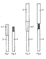
- Figur 1
- in einer Draufsicht ein Kabel mit einer mittels eines Klebebandes umwickelten Isolierung;
- Figur 2
- in einer Draufsicht ein Kabel der Figur 1, jedoch ohne Isolierung;
- Figur 3
- in einer Draufsicht zwei eine isolierte Durchgangsverbindung aufweisende Kabel;
- Figur 4
- in einer Draufsicht die Kabel der Figur 3, jedoch ohne Isolierung um die leitende Durchgangsverbindung;
- Figur 5
- in einer Seitenansicht einen Teil einer Vorrichtung zum Umwickeln eines Bündels von Kabeln mittels eines Klebebandes;
- Figur 6
- in einer Seitenansicht einen Ausschnitt aus der Vorrichtung der Figur 5, zusätzlich mit einem bereitliegenden Bündel;
- Figur 7
- in einer Seitenansicht den Gegenstand der Figur 6, jedoch mit in ein Bandanlagesystem der Vorrichtung eingelegtem Bündel und mit einer Trenneinrichtung zum Durchtrennen des Bandes;
- Figur 8
- in einer Seitenansicht den Gegenstand der Figur 7, jedoch in einem nachfolgenden Verfahrenschritt, wobei eine Banddurchtrennung erfolgte, und zusätzlich mit zwei Federn der Vorrichtung;
- Figur 9
- in einer Seitenansicht den Gegenstand der Figur 8, jedoch in einem weiteren Wickelzustand;
- Figur 10
- in einer Seitenansicht den Gegenstand der Figur 9, jedoch mit einem vollständig umwickelten Bündel und mit einem weiteren, noch zu umwickelnden Bündel Kabel;
- Figur 11
- in einer Seitenansicht eine komplette Vorrichtung, sowie
- Figur 12
- in einer Seitenansicht den Gegenstand der Figur 11, wobei ein Teil der Vorrichtung zum 90 Grad gedreht wurde.
- Eine Vorrichtung 1 (Figuren 11 und 12) dient zum Umwickeln von Kabelstellen (Figuren 1 bis 4) und zum Bündeln von Kabeln (Figuren 5 bis 10). Dabei ist die Betriebsart der Vorrichtung jeweils gleich. In beiden Fällen werden die Gegenstände mittels eines um sie gewickelten Bandes 3, welches ein Klebeband ist, isoliert, miteinander verbunden oder aneinander fixiert.
- Eine Vorrichtung (Figuren 5 bis 12) mit einer Vorratsrolle 4 weist einen Vorschub 5 zum Abziehen des Bandes 3 von der Vorratsrolle 4 und zum Weiterbewegen des Bandes 3 hin zu einem Bandanlegesystem 6 auf. Dabei ist das Bandanlegesystem 6 dazu vorgesehen, einen Abschnitt 7 des Bandes 3 um die Gegenstände zu wickeln. Eine Trenneinrichtung 8 dient zum Abtrennen jeweils eines Abschnitts 7 vom Band 3, sowie ein Schalter 9 zum Starten eines Wickelvorganges.
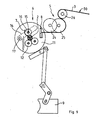
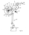
- Das Bandanlegesystem 6 weist eine um eine Achse 10 drehbare Scheibe 11 auf. Es sind zwei Anlegerollen 12 vorgesehen, deren Achsen 13 ortsfest bzgl. der Scheibe 11 auf dieser befestigt sind. Eine an einem Hebel 14 mittels einer Achse 15 drehbar befestigte Anlegerolle 16 ist schwenkbar mit der Scheibe 11 verbunden. Dazu ist der Hebel 14 über ein Drehgelenk 17 mit der Scheibe 11 verbunden. Der Hebel 14 ist über eine Feder 18 gegenüber einem Befestigungspunkt 19 auf der Scheibe 11 vorgespannt. Ein Antrieb 20 ist zum Antreiben der Scheibe 11 vorgesehen.
- Bei einem in das Bandanlegesystem 6 eingelegten Bündel 21 von Kabeln 2 sind die Abstände, die sich jeweils zwischen einer Achse 13, 15 einer Anlegerolle 12, 16 und der Achse 10 der Scheibe 11 erstrecken, annähernd gleich, so dass es während einer Umwickelung des Bündels 21 mit einem Abschnitt 7 des Bandes 3 zu einem ruhigen Umlauf der drei Anlegerollen 12, 16 um das Bündel 21 kommt.
- Um die Anlegerollen 12, 16 dreimal zu einem Umlauf zu bringen, wird die Scheibe 11 dreimal gedreht, was zur Folge hat, dass drei Lagen Band 3 um das Bündel 21 gewickelt werden. Als Antrieb 20 zum Antreiben der Scheibe 11 ist ein Schrittmotor vorgesehen, der über einen geschlossenen Zahnriemen 22 seine Drehbewegung auf ein koaxial mit der Scheibe 11 verbundenes Zahnrad 23 überträgt.
- Ein Vorschub 5 dient dazu, jeweils einen für einen Wickelvorgang benötigten Abschnitt 7 des Bandes 3 vorzuschieben. Dabei wird vor einem Bündeleinlegen zunächst ein wenig Band 3 gespendet, um das Bündel 21 zunächst auf eine Klebstoffseite 30 des Bandes 3 legen zu können, bevor die Scheibe 11 gedreht wird. Der Vorschub 5 weist ein System aus drei Rollen 24, 25, 26 auf, wobei zwei Rollen 24, 25 von einem Antrieb 38 mittels eines Zahnriemens 27 unterschiedlich schnell mittels koaxialer Zahnräder 28, 29 unterschiedlichen Durchmessers angetrieben werden, so dass die beiden Rollen 24, 25 das Band 3, welches mit einer Klebstoffseite 30 an beiden Rollen 24, 25 anliegt, weitertransportieren, und durch die in Bandtransportrichtung nachfolgende, schneller sich drehende Rolle 24 anklebendes Band 3 von der vorherigen, langsamer betriebenen Rolle 25 abgezogen wird. Die dritte Rolle 26 dient zum Anlegen des Bandes 3 an die vorherige Rolle 25. Die Antriebe 20, 38 sind Schrittmotore, die miteinander synchronisiert sind.
- Um den Hebel 14, auf dem die wegschwenkbare Anlegerolle 16 drehbar montiert ist, vor einem Wickelvorgang von den Anlegerollen 12 wegzuschwenken, um ein Bündel 21 in das Bandcinlegesystem 6 einlegen zu können, und um bei eingelegtem Bündel 21 nachfolgend die dritte Anlegerolle 16 an das Band 3 und damit an das Bündel 21 zu setzen, ist ein Hebelsystem 31 mit dem Schalter 9 und mit dem Hebel 14 verbunden. Das Hebelsystem 31 erstreckt sich zwischen einem mit dem Schalter 9 verbundenen Gelenk 32 und zwei ortsfesten Gelenkpunkten 33, 34. Eine Feder 35 ist zum Rückstellen des durch den Schalter 9 versetzten Hebelsystems 31 vorgesehen. Ein freies Hebelende 36 wirkt gegen das freie Ende 37 des Hebels 14, um den Hebel 14 der Scheibe 11 von den Anlegerollen 12 weg zu schwenken. Bei Loslassen des Schalters 9 zieht die Feder 35 das Hebelsystem 31 zurück, wodurch der Hebel 14 der Scheibe 11 freigegeben wird. Zudem ist ein vom Schalter 9 aktivierbarer Mikroschalter 39 für ein Bandspenden vor einem Wickelvorgang durch Betätigen des Schalters 9 sowie eine Betätigung der Trenneinrichtung 8 und des Antriebs 20 zum Antreiben der Scheibe 11 nach einem Loslassen des abgefederten Schalters 9 vorgesehen. Somit wird durch Betätigen und wieder Loslassen des Schalters 9 ein kompletter Wickelvorgang geschaltet. Des weiteren ist eine über eine Stromversorgung 40 mit den Antrieben 20, 38 verbundene Programmiereinrichtung 41 mit einem Display 42 dafür vorgesehen, eine bestimmte Länge der Abschnitte 7 und die Anzahl von drei Umdrehungen der Scheibe 11 für einen Wickelvorgang vorzusehen. Alternativ wäre es möglich, einen Vorwärts-/Rückwärtslauf der Antriebe 20, 38, der für eine Fahnenerzeugung am Bündel 21 nötig wäre, vorzuwählen.
- Ein Stellzylinder 44 ist dazu vorgesehen, über eine Verbindung 45 die Trenneinrichtung 8 zu betätigen.
- Die mit einem Handgriff 43 versehene und als Handgerät ausgeführte Vorrichtung 1 wird derart betrieben, dass stets zunächst das Band 3 mit der Klebstoffseite 30 gegen die zu bündelnden Kabel 2 gelegt wird, und dass die Kabel 2 mitsamt dem anhaftenden Band 3 zwischen die drei Anlegerollen 12, 16 gebracht werden.
- Dann werden einerseits die beiden Anlegerollen 12 und andererseits die Anlegerolle 16 an das Bündel 21 von Kabeln 2 angelegt. Die drei Anlegerollen 12, 16, die um ihre parallel zum Gegenstand bzw, Bündel 21 ausgerichteten Achsen 13, 15 drehbar sind, rollen bei einem Umlauf der Scheibe 11 um das Bündel 21 und rollen das Band 3 um dieses. Abschnittslängenbedingt wird zufuhrseitig das Band 3 durchtrennt.
- 1
- Vorrichtung
- 2
- Kabel
- 3
- Band
- 4
- Vorratsrolle
- 5
- Vorschub
- 6
- Bandanlegesystem
- 7
- Abschnitt
- 8
- Trenneinrichtung
- 9
- Schalter
- 10
- Achse
- 11
- Scheibe
- 12
- Anlegerolle
- 13
- Achse
- 14
- Hebel
- 15
- Achse
- 16
- Anlegerolle
- 17
- Drehgelenk
- 18
- Feder
- 19
- Befestigungspunkt
- 20
- Antrieb
- 21
- Bündel
- 22
- Zahnriemen
- 23
- Zahnrad
- 24, 25, 26
- Rolle
- 27
- Zahnriemen
- 28, 29
- Zahnrad
- 30
- Klebstoffseite
- 31
- Hebelsystem
- 32
- Gelenk
- 33,34
- ortsfester Gelenkpunkt
- 35
- Feder
- 36
- Hebelende
- 37
- freies Ende
- 38
- Antrieb
- 39
- Mikroschalter
- 40
- Stromversorgung
- 41
- Programmiereinrichtung
- 42
- Display
- 43
- Handgriff
- 44
- Stellzylinder
- 45
- Verbindung
Claims (11)
- Vorrichtung (1) zum Umwickeln oder Bündeln von Gegenständen, insbesondere von Kabeln (2), wobei die Gegenstände mittels eines um sie gewickelten Bandes (3), insbesondere eines Klebebandes isoliert, miteinander verbunden oder aneinander fixiert werden, mit einer Vorratsrolle (4), einem Vorschub (5) zum Abziehen des Bandes (3) von der Vorratsrolle (4) und zum Weiterbewegen des Bandes (3) hin zu einem Bandanlegesystem (6), wobei das Bandanlegesystem (6) dazu vorgesehen ist, einen Abschnitt (7) des Bandes (3) um die Gegenstände zu wickeln, mit einer Trenneinrichtung (8) zum Abtrennen jeweils eines Abschnittes (7) vom Band (3), sowie einem Schalter (9) zum Starten eines Wickelvorganges, dadurch gekennzeichnet, dass das Bandanlegesystem (6) eine um eine Achse (10) drehbare Scheibe (11) aufweist, dass zwei Anlegerollen (12) vorgesehen sind, deren Achse (13) ortsfest auf der Scheibe (11) befestigt sind, dass eine an einem Hebel (14) mittels einer Achse (15) drehbar befestigte Anlegerolle (16) derart schwenkbar mit der Scheibe (11) verbunden ist, dass der Hebel (14) über ein Drehgelenk (17) mit der Scheibe (11) verbunden ist, und der Hebel (14) über eine Feder (18) gegenüber einem Befestigungspunkt (19) auf der Scheibe (11) vorgespannt ist, und dass ein Antrieb (20) zum Antreiben der Scheibe (11) vorgesehen ist.
- Vorrichtung nach Anspruch 1, dadurch gekennzeichnet, dass bei in das Bandanlegesystem (6) eingelegtem Bündel (21) von Gegenständen oder eingelgtem Gegenstand die Abstände, die sich jeweils zwischen einer Achse (13, 15) einer Anlegerolle (12, 16) und der Achse (10) der Scheibe (11) erstrecken, gleich oder annähernd gleich sind.
- Vorrichtung nach Anspruch 1 oder Anspruch 2, dadurch gekennzeichnet, dass als Antrieb (20) zum Antreiben der Scheibe (11) ein Schrittmotor vorgesehen ist, der über einen geschlossenen Zahnriemen (22) seine Drehbewegung auf ein koaxial mit der Scheibe (11) verbundenes Zahnrad (23) überträgt.
- Vorrichtung nach Anspruch 1, Anspruch 2 oder Anspruch 3, dadurch gekennzeichnet, dass der Vorschub (5) ein System aus drei Rollen (24, 25, 26) aufweist, wobei zwei Rollen (24, 25) von einem Antrieb (38) mittels eines Zahnriemens (27) unterschiedlich schnell mittels koaxialer Zahnräder (28, 29) unterschiedlichen Durchmessers angetrieben werden, so dass die beiden Rollen (24, 25) das Band (3), welches mit einer Klebstoffseite (30) an beiden Rollen (24, 25) anliegt, weitertransportieren und durch die in Bandtransportrichtung nachfolgende Rolle (24) anklebendes Band (3) von der vorherigen Rolle (25) abgezogen wird, und die dritte Rolle (26) zum Anlegen des Bandes (3) an die vorherige Rolle (25) dient.
- Vorrichtung nach Anspruch 4, dadurch gekennzeichnet, dass als Antriebe (20, 38) miteinander synchronisierte Schrittmotore vorgesehen sind.
- Vorrichtung nach mindestens einem der Ansprüche 1 bis 5, dadurch gekennzeichnet, dass sich ein Hebelsystem (31) zwischen einem mit dem Schalter (9) verbundenen Gelenk (32) und mindestens einem ortsfesten Gelenkpunkt (33, 34) erstreckt, dass eine Feder (35) zum Rückstellen des durch den Schalter (9) versetzten Hebelsystems (31) vorgesehen ist, und dass ein freies Hebelende (36) gegen das freie Ende (37) des Hebels (14) wirkt, um den Hebel (14) der Scheibe (11) von den Anlegerollen (12) weg zu schwenken.
- Vorrichtung nach mindestens einem der Ansprüche 1 bis 6, dadurch gekennzeichnet, dass ein vom Schalter (9) aktivierbarer Mikroschalter (39) für ein Bandspenden vor einem Wickelvorgang durch Betätigen des Schalters (9) sowie eine Betätigung der Trenneinrichtung (8) und des Antriebs (20) zum Antreiben der Scheibe (11) nach einem Loslassen des abgefederten Schalters (9) vorgesehen ist.
- Vorrichtung nach mindestens einem der Ansprüche 1 bis 7, dadurch gekennzeichnet, dass eine über eine Stromversorgung (40) mit den Antrieben (20, 38) verbundene Programmeinrichtung (41), vorzugsweise mit einem Display (42), dafür vorgesehen ist, eine bestimmte Länge der Abschnitte (7), eine bestimmte Anzahl von Umdrehungen der Scheibe (11) für einen Wickelvorgang oder einen Vorwärts-/Rückwärtslauf der Antriebe (20, 38), der für eine Fahnenerzeugung am Bündel (21) nötig ist, vorzuwählen.
- Vorrichtung nach mindestens einem der Ansprüche 1 bis 8, dadurch gekennzeichnet, dass ein Stellzylinder (44) dafür vorgesehen ist, über eine Verbindung (45) die Trenneinrichtung (8) zu betätigen.
- Vorrichtung nach mindestens einem der Ansprüche 1 bis 9, dadurch gekennzeichnet, dass die Vorrichtung (1) als ein mit einem Handgriff (43) versehenes Handgerät ausgestaltet ist.
- Verfahren zum Umwickeln eines länglichen Gegenstandes oder mehrerer länglicher Gegenstände, insbesondere Kabel, dadurch gekennzeichnet, dass zunächst ein Band (3) mit einer Klebstoffseite (30) gegen den Gegenstand bzw. die Gegenstände gelegt wird, und dass der Gegenstand bzw. die Gegenstände mitsamt dem anhaftenden Band (3) zwischen drei Anlegerollen (12, 16) gebracht wird bzw. werden, dass einerseits zwei Anlegerollen (12) und andererseits eine Anlegerolle (16) an den Gegenstand bzw. die Gegenstände angelegt werden, dass die Anlegerollen (12, 16) um ihre parallel zu dem Gegenstand bzw. den Gegenständen ausgerichteten Achsen (13, 15) drehbar sind, so dass bei einem Umlauf der drei Anlegerollen (12, 16) um den Gegenstand bzw. die Gegenstände die Anlegerollen (12, 16) das Band (3) um diesen bzw. diese rollen, und dass das Band (3) zufuhrseitig durchtrennt wird.
Priority Applications (5)
| Application Number | Priority Date | Filing Date | Title |
|---|---|---|---|
| DE502005006954T DE502005006954D1 (de) | 2005-11-15 | 2005-11-15 | Vorrichtung und Verfahren zum Umwickeln oder Bündeln von Gegenständen |
| EP05024955A EP1785354B1 (de) | 2005-11-15 | 2005-11-15 | Vorrichtung und Verfahren zum Umwickeln oder Bündeln von Gegenständen |
| AT05024955T ATE426554T1 (de) | 2005-11-15 | 2005-11-15 | Vorrichtung und verfahren zum umwickeln oder bundeln von gegenstanden |
| PCT/IB2006/054282 WO2007057851A2 (en) | 2005-11-15 | 2006-11-15 | Device and method for wrapping or bundling objects |
| US11/599,856 US20070181244A1 (en) | 2005-11-15 | 2006-11-15 | Device and method for wrapping or bundling objects |
Applications Claiming Priority (1)
| Application Number | Priority Date | Filing Date | Title |
|---|---|---|---|
| EP05024955A EP1785354B1 (de) | 2005-11-15 | 2005-11-15 | Vorrichtung und Verfahren zum Umwickeln oder Bündeln von Gegenständen |
Publications (2)
| Publication Number | Publication Date |
|---|---|
| EP1785354A1 true EP1785354A1 (de) | 2007-05-16 |
| EP1785354B1 EP1785354B1 (de) | 2009-03-25 |
Family
ID=36065034
Family Applications (1)
| Application Number | Title | Priority Date | Filing Date |
|---|---|---|---|
| EP05024955A Expired - Lifetime EP1785354B1 (de) | 2005-11-15 | 2005-11-15 | Vorrichtung und Verfahren zum Umwickeln oder Bündeln von Gegenständen |
Country Status (5)
| Country | Link |
|---|---|
| US (1) | US20070181244A1 (de) |
| EP (1) | EP1785354B1 (de) |
| AT (1) | ATE426554T1 (de) |
| DE (1) | DE502005006954D1 (de) |
| WO (1) | WO2007057851A2 (de) |
Cited By (2)
| Publication number | Priority date | Publication date | Assignee | Title |
|---|---|---|---|---|
| CN105836181A (zh) * | 2016-04-19 | 2016-08-10 | 朱凌 | 一种具备卸力功能的包胶机供料机构及实现方法 |
| CN112722976A (zh) * | 2020-12-25 | 2021-04-30 | 义乌市永胜胶带有限公司 | 一种缠绕胶带设备 |
Families Citing this family (9)
| Publication number | Priority date | Publication date | Assignee | Title |
|---|---|---|---|---|
| DE102008022336A1 (de) * | 2008-04-29 | 2009-11-05 | Newfrey Llc, Newark | Wickelband zum automatisierten Umwickeln von Kabelsträngen |
| US8146491B2 (en) * | 2008-04-29 | 2012-04-03 | Newfrey Llc | Apparatus and method for automatically, circumferentially wrapping a cable harness |
| US8334045B2 (en) * | 2008-04-29 | 2012-12-18 | Newfrey Llc | Wrapping tape for a cable harness |
| US8210483B2 (en) * | 2008-04-29 | 2012-07-03 | Newfrey Llc | Fastening element for a cable harness |
| US8385670B2 (en) * | 2008-08-20 | 2013-02-26 | Microsoft Corporation | Image restoration by vector quantization utilizing visual patterns |
| US9786416B1 (en) * | 2016-03-28 | 2017-10-10 | Te Connectivity Corporation | Tape dispensing tool |
| US20180328531A1 (en) * | 2017-05-10 | 2018-11-15 | Sipp Technologies, Llc | Plugging Apparatus, System and Method for Pipe Lining Applications |
| CN111834138B (zh) * | 2020-08-07 | 2022-05-24 | 四川大学华西医院 | 一种自动扶梯急停按钮 |
| AU2021418958B2 (en) | 2021-01-12 | 2023-06-15 | Torrance Clayne Bistline | Cable wrapping system |
Citations (4)
| Publication number | Priority date | Publication date | Assignee | Title |
|---|---|---|---|---|
| US3063212A (en) * | 1960-10-20 | 1962-11-13 | Possis Machine Corp | Taping machine |
| US4003189A (en) * | 1975-04-18 | 1977-01-18 | Bundy Corporation | Bundling mechanism |
| EP0621182A1 (de) | 1993-04-21 | 1994-10-26 | Wella Aktiengesellschaft | Verfahren zum wahlweisen Bündeln, Markieren und Isolieren von länglichen Gegenständen mittels eines einseitig klebenden Bands sowie eine Vorrichtung zur Durchführung des Verfahrens |
| US5875618A (en) * | 1996-10-28 | 1999-03-02 | Wella Aktiengesellschaft | Hand-held device for bundling elongated objects |
Family Cites Families (2)
| Publication number | Priority date | Publication date | Assignee | Title |
|---|---|---|---|---|
| US4113545A (en) * | 1977-07-29 | 1978-09-12 | Stuart Steel Protection Corporation | Pipe joint wrapping machine |
| US5878618A (en) * | 1995-05-22 | 1999-03-09 | Stalzer; Leo Henry | Machine for bending sheet and plate metal through dual wedge system |
-
2005
- 2005-11-15 EP EP05024955A patent/EP1785354B1/de not_active Expired - Lifetime
- 2005-11-15 DE DE502005006954T patent/DE502005006954D1/de not_active Expired - Lifetime
- 2005-11-15 AT AT05024955T patent/ATE426554T1/de not_active IP Right Cessation
-
2006
- 2006-11-15 WO PCT/IB2006/054282 patent/WO2007057851A2/en not_active Ceased
- 2006-11-15 US US11/599,856 patent/US20070181244A1/en not_active Abandoned
Patent Citations (4)
| Publication number | Priority date | Publication date | Assignee | Title |
|---|---|---|---|---|
| US3063212A (en) * | 1960-10-20 | 1962-11-13 | Possis Machine Corp | Taping machine |
| US4003189A (en) * | 1975-04-18 | 1977-01-18 | Bundy Corporation | Bundling mechanism |
| EP0621182A1 (de) | 1993-04-21 | 1994-10-26 | Wella Aktiengesellschaft | Verfahren zum wahlweisen Bündeln, Markieren und Isolieren von länglichen Gegenständen mittels eines einseitig klebenden Bands sowie eine Vorrichtung zur Durchführung des Verfahrens |
| US5875618A (en) * | 1996-10-28 | 1999-03-02 | Wella Aktiengesellschaft | Hand-held device for bundling elongated objects |
Cited By (3)
| Publication number | Priority date | Publication date | Assignee | Title |
|---|---|---|---|---|
| CN105836181A (zh) * | 2016-04-19 | 2016-08-10 | 朱凌 | 一种具备卸力功能的包胶机供料机构及实现方法 |
| CN112722976A (zh) * | 2020-12-25 | 2021-04-30 | 义乌市永胜胶带有限公司 | 一种缠绕胶带设备 |
| CN112722976B (zh) * | 2020-12-25 | 2023-06-02 | 义乌市永胜胶带有限公司 | 一种缠绕胶带设备 |
Also Published As
| Publication number | Publication date |
|---|---|
| ATE426554T1 (de) | 2009-04-15 |
| WO2007057851A3 (en) | 2007-09-13 |
| EP1785354B1 (de) | 2009-03-25 |
| WO2007057851A2 (en) | 2007-05-24 |
| DE502005006954D1 (de) | 2009-05-07 |
| US20070181244A1 (en) | 2007-08-09 |
Similar Documents
| Publication | Publication Date | Title |
|---|---|---|
| EP1785354B1 (de) | Vorrichtung und Verfahren zum Umwickeln oder Bündeln von Gegenständen | |
| DE102017130895A1 (de) | Wickelvorrichtung und Verfahren zum vollautomatisierten Umwickeln eines Leitungsbündels mit einem Klebeband | |
| WO2015055753A1 (de) | Montagestation sowie verfahren zum automatisierten anbringen von clips an ein leitungsbündel und clipfördereinheit | |
| DE112017001575T5 (de) | Bandabgabewerkzeug | |
| WO2020207559A1 (de) | Vorrichtung zum umwickeln eines elektrischen leitungssatzes | |
| EP4402704B1 (de) | Montagekopf sowie verfahren zur automatisierten umwicklung eines leitungsstrangs | |
| DE2628608A1 (de) | Vorrichtung zum binden von gegenstaenden mittels eines bandes | |
| DE69917627T2 (de) | Verfahren und Maschine zum Verpacken von ringförmigen Strängen eines flexiblen länglichen Elements | |
| EP0179997B1 (de) | Vorrichtung zum Verpacken von Kleinstückgütern, wie Salatköpfe, zu einem Bund zusammengelegte Mohrrüben, Spargel, Bananen u. dgl. | |
| DE102019005933A1 (de) | Verfahren und Vorrichtung zum Umwickeln eines Leitungssatzes für einen Kraftwagen mit einem Klebeband | |
| DE2312512B2 (de) | Vorrichtung zum Einführen von aus einem Rückenteil und mehreren davon abstehenden eingerollten Fingern bestehenden Bindeelementen zum Binden von am Rande perforierten Blättern | |
| DE4212789C1 (de) | ||
| EP4148749B1 (de) | Verfahren und vorrichtung zum automatischen aufbringen eines einseitig klebenden klebebandes auf einem kabel oder kabelende | |
| DE102021117669A1 (de) | Kabelwickelsystem | |
| DE3532022A1 (de) | Verfahren zum wickeln einer elektrodenanordnung | |
| EP1445228B1 (de) | Vorrichtung zur Halterung von Leitungen | |
| DE102019121634A1 (de) | Abbinder und Verfahren zum Betreiben eines Abbinders | |
| CH701764B1 (de) | Vorrichtung und Verfahren zum Abbinden von ringförmigem Wickelgut. | |
| WO1997017260A1 (de) | Verfahren zum binden von gebündelten gegenständen, insbesondere kabelstücken, sowie dazugehörige vorrichtung und ein bindematerial | |
| EP1541008A1 (de) | Umwickeln mit nur einem Folienende | |
| DE1611846B2 (de) | Vorrichtung zum umbinden von buendeln, insbesondere von gebuendelten walzwerkerzeugnissen | |
| DE19548735A1 (de) | Vorrichtung zum Bündeln und Binden von Balken oder Stäben | |
| DE1499049C (de) | Vorrichtung zum Wickeln von Papieroder Folienröllchen aus einem zur Hochspannungsisolation dienenden Material | |
| DE102022116494B4 (de) | Stationäres vollautomatisiertes bandagieren und halteteilsetzen | |
| DE489339C (de) | Maschine zum Buendeln und Bebaendern (Etikettieren) von Schnuersenkeln |
Legal Events
| Date | Code | Title | Description |
|---|---|---|---|
| PUAI | Public reference made under article 153(3) epc to a published international application that has entered the european phase |
Free format text: ORIGINAL CODE: 0009012 |
|
| 17P | Request for examination filed |
Effective date: 20051115 |
|
| AK | Designated contracting states |
Kind code of ref document: A1 Designated state(s): AT BE BG CH CY CZ DE DK EE ES FI FR GB GR HU IE IS IT LI LT LU LV MC NL PL PT RO SE SI SK TR |
|
| AX | Request for extension of the european patent |
Extension state: AL BA HR MK YU |
|
| 17Q | First examination report despatched |
Effective date: 20071011 |
|
| RAP1 | Party data changed (applicant data changed or rights of an application transferred) |
Owner name: ONDAL 5 GMBH |
|
| AKX | Designation fees paid |
Designated state(s): AT BE BG CH CY CZ DE DK EE ES FI FR GB GR HU IE IS IT LI LT LU LV MC NL PL PT RO SE SI SK TR |
|
| REG | Reference to a national code |
Ref country code: HK Ref legal event code: DE Ref document number: 1108675 Country of ref document: HK |
|
| GRAP | Despatch of communication of intention to grant a patent |
Free format text: ORIGINAL CODE: EPIDOSNIGR1 |
|
| GRAS | Grant fee paid |
Free format text: ORIGINAL CODE: EPIDOSNIGR3 |
|
| GRAA | (expected) grant |
Free format text: ORIGINAL CODE: 0009210 |
|
| AK | Designated contracting states |
Kind code of ref document: B1 Designated state(s): AT BE BG CH CY CZ DE DK EE ES FI FR GB GR HU IE IS IT LI LT LU LV MC NL PL PT RO SE SI SK TR |
|
| REG | Reference to a national code |
Ref country code: GB Ref legal event code: FG4D Free format text: NOT ENGLISH |
|
| REG | Reference to a national code |
Ref country code: CH Ref legal event code: EP |
|
| REG | Reference to a national code |
Ref country code: IE Ref legal event code: FG4D Free format text: LANGUAGE OF EP DOCUMENT: GERMAN |
|
| REF | Corresponds to: |
Ref document number: 502005006954 Country of ref document: DE Date of ref document: 20090507 Kind code of ref document: P |
|
| PG25 | Lapsed in a contracting state [announced via postgrant information from national office to epo] |
Ref country code: SI Free format text: LAPSE BECAUSE OF FAILURE TO SUBMIT A TRANSLATION OF THE DESCRIPTION OR TO PAY THE FEE WITHIN THE PRESCRIBED TIME-LIMIT Effective date: 20090325 Ref country code: LT Free format text: LAPSE BECAUSE OF FAILURE TO SUBMIT A TRANSLATION OF THE DESCRIPTION OR TO PAY THE FEE WITHIN THE PRESCRIBED TIME-LIMIT Effective date: 20090325 Ref country code: FI Free format text: LAPSE BECAUSE OF FAILURE TO SUBMIT A TRANSLATION OF THE DESCRIPTION OR TO PAY THE FEE WITHIN THE PRESCRIBED TIME-LIMIT Effective date: 20090325 |
|
| PG25 | Lapsed in a contracting state [announced via postgrant information from national office to epo] |
Ref country code: LV Free format text: LAPSE BECAUSE OF FAILURE TO SUBMIT A TRANSLATION OF THE DESCRIPTION OR TO PAY THE FEE WITHIN THE PRESCRIBED TIME-LIMIT Effective date: 20090325 Ref country code: SE Free format text: LAPSE BECAUSE OF FAILURE TO SUBMIT A TRANSLATION OF THE DESCRIPTION OR TO PAY THE FEE WITHIN THE PRESCRIBED TIME-LIMIT Effective date: 20090625 Ref country code: PL Free format text: LAPSE BECAUSE OF FAILURE TO SUBMIT A TRANSLATION OF THE DESCRIPTION OR TO PAY THE FEE WITHIN THE PRESCRIBED TIME-LIMIT Effective date: 20090325 |
|
| NLV1 | Nl: lapsed or annulled due to failure to fulfill the requirements of art. 29p and 29m of the patents act | ||
| REG | Reference to a national code |
Ref country code: IE Ref legal event code: FD4D |
|
| PG25 | Lapsed in a contracting state [announced via postgrant information from national office to epo] |
Ref country code: PT Free format text: LAPSE BECAUSE OF FAILURE TO SUBMIT A TRANSLATION OF THE DESCRIPTION OR TO PAY THE FEE WITHIN THE PRESCRIBED TIME-LIMIT Effective date: 20090901 Ref country code: CZ Free format text: LAPSE BECAUSE OF FAILURE TO SUBMIT A TRANSLATION OF THE DESCRIPTION OR TO PAY THE FEE WITHIN THE PRESCRIBED TIME-LIMIT Effective date: 20090325 Ref country code: EE Free format text: LAPSE BECAUSE OF FAILURE TO SUBMIT A TRANSLATION OF THE DESCRIPTION OR TO PAY THE FEE WITHIN THE PRESCRIBED TIME-LIMIT Effective date: 20090325 Ref country code: ES Free format text: LAPSE BECAUSE OF FAILURE TO SUBMIT A TRANSLATION OF THE DESCRIPTION OR TO PAY THE FEE WITHIN THE PRESCRIBED TIME-LIMIT Effective date: 20090706 |
|
| PG25 | Lapsed in a contracting state [announced via postgrant information from national office to epo] |
Ref country code: RO Free format text: LAPSE BECAUSE OF FAILURE TO SUBMIT A TRANSLATION OF THE DESCRIPTION OR TO PAY THE FEE WITHIN THE PRESCRIBED TIME-LIMIT Effective date: 20090325 Ref country code: NL Free format text: LAPSE BECAUSE OF FAILURE TO SUBMIT A TRANSLATION OF THE DESCRIPTION OR TO PAY THE FEE WITHIN THE PRESCRIBED TIME-LIMIT Effective date: 20090325 Ref country code: SK Free format text: LAPSE BECAUSE OF FAILURE TO SUBMIT A TRANSLATION OF THE DESCRIPTION OR TO PAY THE FEE WITHIN THE PRESCRIBED TIME-LIMIT Effective date: 20090325 Ref country code: IS Free format text: LAPSE BECAUSE OF FAILURE TO SUBMIT A TRANSLATION OF THE DESCRIPTION OR TO PAY THE FEE WITHIN THE PRESCRIBED TIME-LIMIT Effective date: 20090725 |
|
| PG25 | Lapsed in a contracting state [announced via postgrant information from national office to epo] |
Ref country code: BG Free format text: LAPSE BECAUSE OF FAILURE TO SUBMIT A TRANSLATION OF THE DESCRIPTION OR TO PAY THE FEE WITHIN THE PRESCRIBED TIME-LIMIT Effective date: 20090625 Ref country code: DK Free format text: LAPSE BECAUSE OF FAILURE TO SUBMIT A TRANSLATION OF THE DESCRIPTION OR TO PAY THE FEE WITHIN THE PRESCRIBED TIME-LIMIT Effective date: 20090325 Ref country code: IE Free format text: LAPSE BECAUSE OF FAILURE TO SUBMIT A TRANSLATION OF THE DESCRIPTION OR TO PAY THE FEE WITHIN THE PRESCRIBED TIME-LIMIT Effective date: 20090325 |
|
| PLBE | No opposition filed within time limit |
Free format text: ORIGINAL CODE: 0009261 |
|
| STAA | Information on the status of an ep patent application or granted ep patent |
Free format text: STATUS: NO OPPOSITION FILED WITHIN TIME LIMIT |
|
| 26N | No opposition filed |
Effective date: 20091229 |
|
| BERE | Be: lapsed |
Owner name: ONDAL 5 G.M.B.H. Effective date: 20091130 |
|
| PG25 | Lapsed in a contracting state [announced via postgrant information from national office to epo] |
Ref country code: MC Free format text: LAPSE BECAUSE OF NON-PAYMENT OF DUE FEES Effective date: 20091130 |
|
| PGFP | Annual fee paid to national office [announced via postgrant information from national office to epo] |
Ref country code: DE Payment date: 20091214 Year of fee payment: 5 |
|
| REG | Reference to a national code |
Ref country code: CH Ref legal event code: PL |
|
| GBPC | Gb: european patent ceased through non-payment of renewal fee |
Effective date: 20091115 |
|
| REG | Reference to a national code |
Ref country code: FR Ref legal event code: ST Effective date: 20100730 |
|
| PG25 | Lapsed in a contracting state [announced via postgrant information from national office to epo] |
Ref country code: FR Free format text: LAPSE BECAUSE OF NON-PAYMENT OF DUE FEES Effective date: 20091130 Ref country code: BE Free format text: LAPSE BECAUSE OF NON-PAYMENT OF DUE FEES Effective date: 20091130 Ref country code: CH Free format text: LAPSE BECAUSE OF NON-PAYMENT OF DUE FEES Effective date: 20091130 Ref country code: GR Free format text: LAPSE BECAUSE OF FAILURE TO SUBMIT A TRANSLATION OF THE DESCRIPTION OR TO PAY THE FEE WITHIN THE PRESCRIBED TIME-LIMIT Effective date: 20090626 Ref country code: LI Free format text: LAPSE BECAUSE OF NON-PAYMENT OF DUE FEES Effective date: 20091130 |
|
| PG25 | Lapsed in a contracting state [announced via postgrant information from national office to epo] |
Ref country code: GB Free format text: LAPSE BECAUSE OF NON-PAYMENT OF DUE FEES Effective date: 20091115 |
|
| PG25 | Lapsed in a contracting state [announced via postgrant information from national office to epo] |
Ref country code: AT Free format text: LAPSE BECAUSE OF NON-PAYMENT OF DUE FEES Effective date: 20091115 |
|
| PG25 | Lapsed in a contracting state [announced via postgrant information from national office to epo] |
Ref country code: IT Free format text: LAPSE BECAUSE OF FAILURE TO SUBMIT A TRANSLATION OF THE DESCRIPTION OR TO PAY THE FEE WITHIN THE PRESCRIBED TIME-LIMIT Effective date: 20090325 |
|
| PG25 | Lapsed in a contracting state [announced via postgrant information from national office to epo] |
Ref country code: LU Free format text: LAPSE BECAUSE OF NON-PAYMENT OF DUE FEES Effective date: 20091115 |
|
| PG25 | Lapsed in a contracting state [announced via postgrant information from national office to epo] |
Ref country code: HU Free format text: LAPSE BECAUSE OF FAILURE TO SUBMIT A TRANSLATION OF THE DESCRIPTION OR TO PAY THE FEE WITHIN THE PRESCRIBED TIME-LIMIT Effective date: 20090926 |
|
| PG25 | Lapsed in a contracting state [announced via postgrant information from national office to epo] |
Ref country code: TR Free format text: LAPSE BECAUSE OF FAILURE TO SUBMIT A TRANSLATION OF THE DESCRIPTION OR TO PAY THE FEE WITHIN THE PRESCRIBED TIME-LIMIT Effective date: 20090325 |
|
| PG25 | Lapsed in a contracting state [announced via postgrant information from national office to epo] |
Ref country code: CY Free format text: LAPSE BECAUSE OF FAILURE TO SUBMIT A TRANSLATION OF THE DESCRIPTION OR TO PAY THE FEE WITHIN THE PRESCRIBED TIME-LIMIT Effective date: 20090325 |
|
| REG | Reference to a national code |
Ref country code: DE Ref legal event code: R119 Ref document number: 502005006954 Country of ref document: DE Effective date: 20110601 Ref country code: DE Ref legal event code: R119 Ref document number: 502005006954 Country of ref document: DE Effective date: 20110531 |
|
| PG25 | Lapsed in a contracting state [announced via postgrant information from national office to epo] |
Ref country code: DE Free format text: LAPSE BECAUSE OF NON-PAYMENT OF DUE FEES Effective date: 20110531 |
|
| REG | Reference to a national code |
Ref country code: HK Ref legal event code: WD Ref document number: 1108675 Country of ref document: HK |