EP1785253A1 - Process for producing molded item and apparatus therefor - Google Patents
Process for producing molded item and apparatus therefor Download PDFInfo
- Publication number
- EP1785253A1 EP1785253A1 EP05780446A EP05780446A EP1785253A1 EP 1785253 A1 EP1785253 A1 EP 1785253A1 EP 05780446 A EP05780446 A EP 05780446A EP 05780446 A EP05780446 A EP 05780446A EP 1785253 A1 EP1785253 A1 EP 1785253A1
- Authority
- EP
- European Patent Office
- Prior art keywords
- resin
- metal mold
- molten resin
- mold
- thermoplastic resin
- Prior art date
- Legal status (The legal status is an assumption and is not a legal conclusion. Google has not performed a legal analysis and makes no representation as to the accuracy of the status listed.)
- Granted
Links
- 238000000034 method Methods 0.000 title claims abstract description 77
- 230000008569 process Effects 0.000 title abstract description 10
- 229920005989 resin Polymers 0.000 claims abstract description 503
- 239000011347 resin Substances 0.000 claims abstract description 503
- 238000000576 coating method Methods 0.000 claims abstract description 182
- 239000011248 coating agent Substances 0.000 claims abstract description 181
- 238000004519 manufacturing process Methods 0.000 claims abstract description 85
- 238000003825 pressing Methods 0.000 claims abstract description 57
- 238000001816 cooling Methods 0.000 claims abstract description 28
- 239000002184 metal Substances 0.000 claims description 183
- 229910052751 metal Inorganic materials 0.000 claims description 183
- 229920005992 thermoplastic resin Polymers 0.000 claims description 80
- 238000010438 heat treatment Methods 0.000 claims description 33
- 238000007599 discharging Methods 0.000 claims description 15
- 230000033001 locomotion Effects 0.000 claims description 13
- 238000011144 upstream manufacturing Methods 0.000 claims description 3
- 238000000465 moulding Methods 0.000 abstract description 16
- 239000000463 material Substances 0.000 description 17
- 230000003287 optical effect Effects 0.000 description 14
- 230000007246 mechanism Effects 0.000 description 10
- 238000001746 injection moulding Methods 0.000 description 9
- 229920003229 poly(methyl methacrylate) Polymers 0.000 description 9
- 239000004926 polymethyl methacrylate Substances 0.000 description 9
- 239000012528 membrane Substances 0.000 description 8
- XLYOFNOQVPJJNP-UHFFFAOYSA-N water Substances O XLYOFNOQVPJJNP-UHFFFAOYSA-N 0.000 description 8
- 239000012530 fluid Substances 0.000 description 7
- 238000002347 injection Methods 0.000 description 7
- 239000007924 injection Substances 0.000 description 7
- PXHVJJICTQNCMI-UHFFFAOYSA-N Nickel Chemical compound [Ni] PXHVJJICTQNCMI-UHFFFAOYSA-N 0.000 description 6
- 238000002844 melting Methods 0.000 description 6
- 230000008018 melting Effects 0.000 description 6
- 230000015556 catabolic process Effects 0.000 description 4
- 238000006731 degradation reaction Methods 0.000 description 4
- 239000010410 layer Substances 0.000 description 4
- 239000007788 liquid Substances 0.000 description 4
- 230000002093 peripheral effect Effects 0.000 description 4
- -1 polyethylene Polymers 0.000 description 4
- 239000000758 substrate Substances 0.000 description 4
- 239000002344 surface layer Substances 0.000 description 4
- 239000004698 Polyethylene Substances 0.000 description 3
- 238000006243 chemical reaction Methods 0.000 description 3
- 238000004891 communication Methods 0.000 description 3
- 230000006835 compression Effects 0.000 description 3
- 238000007906 compression Methods 0.000 description 3
- 230000000694 effects Effects 0.000 description 3
- 229910052736 halogen Inorganic materials 0.000 description 3
- 150000002367 halogens Chemical class 0.000 description 3
- 229910052759 nickel Inorganic materials 0.000 description 3
- 239000003921 oil Substances 0.000 description 3
- 229920000573 polyethylene Polymers 0.000 description 3
- 239000000843 powder Substances 0.000 description 3
- 239000010935 stainless steel Substances 0.000 description 3
- 229910001220 stainless steel Inorganic materials 0.000 description 3
- 238000012546 transfer Methods 0.000 description 3
- PFNQVRZLDWYSCW-UHFFFAOYSA-N (fluoren-9-ylideneamino) n-naphthalen-1-ylcarbamate Chemical compound C12=CC=CC=C2C2=CC=CC=C2C1=NOC(=O)NC1=CC=CC2=CC=CC=C12 PFNQVRZLDWYSCW-UHFFFAOYSA-N 0.000 description 2
- OKTJSMMVPCPJKN-UHFFFAOYSA-N Carbon Chemical compound [C] OKTJSMMVPCPJKN-UHFFFAOYSA-N 0.000 description 2
- 229920000089 Cyclic olefin copolymer Polymers 0.000 description 2
- 238000000018 DNA microarray Methods 0.000 description 2
- 241001025261 Neoraja caerulea Species 0.000 description 2
- 239000004952 Polyamide Substances 0.000 description 2
- 239000004642 Polyimide Substances 0.000 description 2
- 239000004721 Polyphenylene oxide Substances 0.000 description 2
- 239000004743 Polypropylene Substances 0.000 description 2
- 229910052799 carbon Inorganic materials 0.000 description 2
- 230000008859 change Effects 0.000 description 2
- 239000005038 ethylene vinyl acetate Substances 0.000 description 2
- 239000000203 mixture Substances 0.000 description 2
- 229920001200 poly(ethylene-vinyl acetate) Polymers 0.000 description 2
- 229920002647 polyamide Polymers 0.000 description 2
- 229920001230 polyarylate Polymers 0.000 description 2
- 229920001721 polyimide Polymers 0.000 description 2
- 229920006324 polyoxymethylene Polymers 0.000 description 2
- 229920006380 polyphenylene oxide Polymers 0.000 description 2
- 229920001155 polypropylene Polymers 0.000 description 2
- 229920001296 polysiloxane Polymers 0.000 description 2
- 230000003449 preventive effect Effects 0.000 description 2
- 230000009467 reduction Effects 0.000 description 2
- 239000003381 stabilizer Substances 0.000 description 2
- 230000003746 surface roughness Effects 0.000 description 2
- 238000013519 translation Methods 0.000 description 2
- 229910000990 Ni alloy Inorganic materials 0.000 description 1
- 229930182556 Polyacetal Natural products 0.000 description 1
- XUIMIQQOPSSXEZ-UHFFFAOYSA-N Silicon Chemical compound [Si] XUIMIQQOPSSXEZ-UHFFFAOYSA-N 0.000 description 1
- XECAHXYUAAWDEL-UHFFFAOYSA-N acrylonitrile butadiene styrene Chemical compound C=CC=C.C=CC#N.C=CC1=CC=CC=C1 XECAHXYUAAWDEL-UHFFFAOYSA-N 0.000 description 1
- 239000000654 additive Substances 0.000 description 1
- 229920006109 alicyclic polymer Polymers 0.000 description 1
- 239000002216 antistatic agent Substances 0.000 description 1
- 230000005540 biological transmission Effects 0.000 description 1
- 230000015572 biosynthetic process Effects 0.000 description 1
- 239000002981 blocking agent Substances 0.000 description 1
- DQXBYHZEEUGOBF-UHFFFAOYSA-N but-3-enoic acid;ethene Chemical compound C=C.OC(=O)CC=C DQXBYHZEEUGOBF-UHFFFAOYSA-N 0.000 description 1
- 230000001413 cellular effect Effects 0.000 description 1
- 239000003795 chemical substances by application Substances 0.000 description 1
- 230000001143 conditioned effect Effects 0.000 description 1
- 238000012790 confirmation Methods 0.000 description 1
- 238000007334 copolymerization reaction Methods 0.000 description 1
- 230000003247 decreasing effect Effects 0.000 description 1
- 230000007547 defect Effects 0.000 description 1
- 230000002950 deficient Effects 0.000 description 1
- 239000003989 dielectric material Substances 0.000 description 1
- 239000000975 dye Substances 0.000 description 1
- 238000009713 electroplating Methods 0.000 description 1
- 238000003891 environmental analysis Methods 0.000 description 1
- 239000000945 filler Substances 0.000 description 1
- 229920005570 flexible polymer Polymers 0.000 description 1
- 239000000446 fuel Substances 0.000 description 1
- 210000004907 gland Anatomy 0.000 description 1
- 239000011521 glass Substances 0.000 description 1
- 239000003365 glass fiber Substances 0.000 description 1
- 230000009477 glass transition Effects 0.000 description 1
- 239000004973 liquid crystal related substance Substances 0.000 description 1
- 239000000314 lubricant Substances 0.000 description 1
- 238000005259 measurement Methods 0.000 description 1
- 239000003595 mist Substances 0.000 description 1
- 238000012986 modification Methods 0.000 description 1
- 230000004048 modification Effects 0.000 description 1
- 239000006082 mold release agent Substances 0.000 description 1
- 239000012768 molten material Substances 0.000 description 1
- 238000012856 packing Methods 0.000 description 1
- 230000035515 penetration Effects 0.000 description 1
- 238000000206 photolithography Methods 0.000 description 1
- 239000000049 pigment Substances 0.000 description 1
- 239000011295 pitch Substances 0.000 description 1
- 229920001748 polybutylene Polymers 0.000 description 1
- 239000004417 polycarbonate Substances 0.000 description 1
- 229920000515 polycarbonate Polymers 0.000 description 1
- 229920000642 polymer Polymers 0.000 description 1
- 239000002952 polymeric resin Substances 0.000 description 1
- 239000004800 polyvinyl chloride Substances 0.000 description 1
- 239000011148 porous material Substances 0.000 description 1
- 102000004169 proteins and genes Human genes 0.000 description 1
- 108090000623 proteins and genes Proteins 0.000 description 1
- 239000004065 semiconductor Substances 0.000 description 1
- 229910052710 silicon Inorganic materials 0.000 description 1
- 239000010703 silicon Substances 0.000 description 1
- 238000005549 size reduction Methods 0.000 description 1
- 239000012748 slip agent Substances 0.000 description 1
- 239000007921 spray Substances 0.000 description 1
- 238000005507 spraying Methods 0.000 description 1
- 238000000992 sputter etching Methods 0.000 description 1
- 239000000126 substance Substances 0.000 description 1
- 229920001169 thermoplastic Polymers 0.000 description 1
- 239000004416 thermosoftening plastic Substances 0.000 description 1
- 238000013518 transcription Methods 0.000 description 1
- 230000035897 transcription Effects 0.000 description 1
- 238000002834 transmittance Methods 0.000 description 1
Images


Classifications
-
- B—PERFORMING OPERATIONS; TRANSPORTING
- B29—WORKING OF PLASTICS; WORKING OF SUBSTANCES IN A PLASTIC STATE IN GENERAL
- B29C—SHAPING OR JOINING OF PLASTICS; SHAPING OF MATERIAL IN A PLASTIC STATE, NOT OTHERWISE PROVIDED FOR; AFTER-TREATMENT OF THE SHAPED PRODUCTS, e.g. REPAIRING
- B29C43/00—Compression moulding, i.e. applying external pressure to flow the moulding material; Apparatus therefor
- B29C43/02—Compression moulding, i.e. applying external pressure to flow the moulding material; Apparatus therefor of articles of definite length, i.e. discrete articles
- B29C43/021—Compression moulding, i.e. applying external pressure to flow the moulding material; Apparatus therefor of articles of definite length, i.e. discrete articles characterised by the shape of the surface
-
- B—PERFORMING OPERATIONS; TRANSPORTING
- B29—WORKING OF PLASTICS; WORKING OF SUBSTANCES IN A PLASTIC STATE IN GENERAL
- B29C—SHAPING OR JOINING OF PLASTICS; SHAPING OF MATERIAL IN A PLASTIC STATE, NOT OTHERWISE PROVIDED FOR; AFTER-TREATMENT OF THE SHAPED PRODUCTS, e.g. REPAIRING
- B29C43/00—Compression moulding, i.e. applying external pressure to flow the moulding material; Apparatus therefor
- B29C43/02—Compression moulding, i.e. applying external pressure to flow the moulding material; Apparatus therefor of articles of definite length, i.e. discrete articles
-
- B—PERFORMING OPERATIONS; TRANSPORTING
- B29—WORKING OF PLASTICS; WORKING OF SUBSTANCES IN A PLASTIC STATE IN GENERAL
- B29C—SHAPING OR JOINING OF PLASTICS; SHAPING OF MATERIAL IN A PLASTIC STATE, NOT OTHERWISE PROVIDED FOR; AFTER-TREATMENT OF THE SHAPED PRODUCTS, e.g. REPAIRING
- B29C31/00—Handling, e.g. feeding of the material to be shaped, storage of plastics material before moulding; Automation, i.e. automated handling lines in plastics processing plants, e.g. using manipulators or robots
- B29C31/04—Feeding of the material to be moulded, e.g. into a mould cavity
- B29C31/042—Feeding of the material to be moulded, e.g. into a mould cavity using dispensing heads, e.g. extruders, placed over or apart from the moulds
- B29C31/044—Feeding of the material to be moulded, e.g. into a mould cavity using dispensing heads, e.g. extruders, placed over or apart from the moulds with moving heads for distributing liquid or viscous material into the moulds
- B29C31/045—Feeding of the material to be moulded, e.g. into a mould cavity using dispensing heads, e.g. extruders, placed over or apart from the moulds with moving heads for distributing liquid or viscous material into the moulds moving along predetermined circuits or distributing the material according to predetermined patterns
-
- B—PERFORMING OPERATIONS; TRANSPORTING
- B29—WORKING OF PLASTICS; WORKING OF SUBSTANCES IN A PLASTIC STATE IN GENERAL
- B29C—SHAPING OR JOINING OF PLASTICS; SHAPING OF MATERIAL IN A PLASTIC STATE, NOT OTHERWISE PROVIDED FOR; AFTER-TREATMENT OF THE SHAPED PRODUCTS, e.g. REPAIRING
- B29C31/00—Handling, e.g. feeding of the material to be shaped, storage of plastics material before moulding; Automation, i.e. automated handling lines in plastics processing plants, e.g. using manipulators or robots
- B29C31/04—Feeding of the material to be moulded, e.g. into a mould cavity
- B29C31/06—Feeding of the material to be moulded, e.g. into a mould cavity in measured doses, e.g. by weighting
- B29C31/065—Feeding of the material to be moulded, e.g. into a mould cavity in measured doses, e.g. by weighting using volumetric measuring chambers moving between a charging station and a discharge station
- B29C31/068—Feeding of the material to be moulded, e.g. into a mould cavity in measured doses, e.g. by weighting using volumetric measuring chambers moving between a charging station and a discharge station of the piston type
-
- B—PERFORMING OPERATIONS; TRANSPORTING
- B29—WORKING OF PLASTICS; WORKING OF SUBSTANCES IN A PLASTIC STATE IN GENERAL
- B29C—SHAPING OR JOINING OF PLASTICS; SHAPING OF MATERIAL IN A PLASTIC STATE, NOT OTHERWISE PROVIDED FOR; AFTER-TREATMENT OF THE SHAPED PRODUCTS, e.g. REPAIRING
- B29C43/00—Compression moulding, i.e. applying external pressure to flow the moulding material; Apparatus therefor
- B29C43/32—Component parts, details or accessories; Auxiliary operations
- B29C43/34—Feeding the material to the mould or the compression means
-
- B—PERFORMING OPERATIONS; TRANSPORTING
- B29—WORKING OF PLASTICS; WORKING OF SUBSTANCES IN A PLASTIC STATE IN GENERAL
- B29C—SHAPING OR JOINING OF PLASTICS; SHAPING OF MATERIAL IN A PLASTIC STATE, NOT OTHERWISE PROVIDED FOR; AFTER-TREATMENT OF THE SHAPED PRODUCTS, e.g. REPAIRING
- B29C43/00—Compression moulding, i.e. applying external pressure to flow the moulding material; Apparatus therefor
- B29C43/32—Component parts, details or accessories; Auxiliary operations
- B29C43/36—Moulds for making articles of definite length, i.e. discrete articles
-
- B—PERFORMING OPERATIONS; TRANSPORTING
- B29—WORKING OF PLASTICS; WORKING OF SUBSTANCES IN A PLASTIC STATE IN GENERAL
- B29C—SHAPING OR JOINING OF PLASTICS; SHAPING OF MATERIAL IN A PLASTIC STATE, NOT OTHERWISE PROVIDED FOR; AFTER-TREATMENT OF THE SHAPED PRODUCTS, e.g. REPAIRING
- B29C43/00—Compression moulding, i.e. applying external pressure to flow the moulding material; Apparatus therefor
- B29C43/32—Component parts, details or accessories; Auxiliary operations
- B29C43/52—Heating or cooling
-
- B—PERFORMING OPERATIONS; TRANSPORTING
- B29—WORKING OF PLASTICS; WORKING OF SUBSTANCES IN A PLASTIC STATE IN GENERAL
- B29C—SHAPING OR JOINING OF PLASTICS; SHAPING OF MATERIAL IN A PLASTIC STATE, NOT OTHERWISE PROVIDED FOR; AFTER-TREATMENT OF THE SHAPED PRODUCTS, e.g. REPAIRING
- B29C48/00—Extrusion moulding, i.e. expressing the moulding material through a die or nozzle which imparts the desired form; Apparatus therefor
- B29C48/03—Extrusion moulding, i.e. expressing the moulding material through a die or nozzle which imparts the desired form; Apparatus therefor characterised by the shape of the extruded material at extrusion
- B29C48/07—Flat, e.g. panels
- B29C48/08—Flat, e.g. panels flexible, e.g. films
-
- B—PERFORMING OPERATIONS; TRANSPORTING
- B29—WORKING OF PLASTICS; WORKING OF SUBSTANCES IN A PLASTIC STATE IN GENERAL
- B29C—SHAPING OR JOINING OF PLASTICS; SHAPING OF MATERIAL IN A PLASTIC STATE, NOT OTHERWISE PROVIDED FOR; AFTER-TREATMENT OF THE SHAPED PRODUCTS, e.g. REPAIRING
- B29C48/00—Extrusion moulding, i.e. expressing the moulding material through a die or nozzle which imparts the desired form; Apparatus therefor
- B29C48/03—Extrusion moulding, i.e. expressing the moulding material through a die or nozzle which imparts the desired form; Apparatus therefor characterised by the shape of the extruded material at extrusion
- B29C48/12—Articles with an irregular circumference when viewed in cross-section, e.g. window profiles
-
- B—PERFORMING OPERATIONS; TRANSPORTING
- B29—WORKING OF PLASTICS; WORKING OF SUBSTANCES IN A PLASTIC STATE IN GENERAL
- B29C—SHAPING OR JOINING OF PLASTICS; SHAPING OF MATERIAL IN A PLASTIC STATE, NOT OTHERWISE PROVIDED FOR; AFTER-TREATMENT OF THE SHAPED PRODUCTS, e.g. REPAIRING
- B29C48/00—Extrusion moulding, i.e. expressing the moulding material through a die or nozzle which imparts the desired form; Apparatus therefor
- B29C48/03—Extrusion moulding, i.e. expressing the moulding material through a die or nozzle which imparts the desired form; Apparatus therefor characterised by the shape of the extruded material at extrusion
- B29C48/13—Articles with a cross-section varying in the longitudinal direction, e.g. corrugated pipes
-
- B—PERFORMING OPERATIONS; TRANSPORTING
- B29—WORKING OF PLASTICS; WORKING OF SUBSTANCES IN A PLASTIC STATE IN GENERAL
- B29C—SHAPING OR JOINING OF PLASTICS; SHAPING OF MATERIAL IN A PLASTIC STATE, NOT OTHERWISE PROVIDED FOR; AFTER-TREATMENT OF THE SHAPED PRODUCTS, e.g. REPAIRING
- B29C48/00—Extrusion moulding, i.e. expressing the moulding material through a die or nozzle which imparts the desired form; Apparatus therefor
- B29C48/25—Component parts, details or accessories; Auxiliary operations
- B29C48/255—Flow control means, e.g. valves
-
- B—PERFORMING OPERATIONS; TRANSPORTING
- B29—WORKING OF PLASTICS; WORKING OF SUBSTANCES IN A PLASTIC STATE IN GENERAL
- B29C—SHAPING OR JOINING OF PLASTICS; SHAPING OF MATERIAL IN A PLASTIC STATE, NOT OTHERWISE PROVIDED FOR; AFTER-TREATMENT OF THE SHAPED PRODUCTS, e.g. REPAIRING
- B29C48/00—Extrusion moulding, i.e. expressing the moulding material through a die or nozzle which imparts the desired form; Apparatus therefor
- B29C48/25—Component parts, details or accessories; Auxiliary operations
- B29C48/36—Means for plasticising or homogenising the moulding material or forcing it through the nozzle or die
- B29C48/375—Plasticisers, homogenisers or feeders comprising two or more stages
- B29C48/388—Plasticisers, homogenisers or feeders comprising two or more stages using a screw extruder and a ram or piston
-
- B—PERFORMING OPERATIONS; TRANSPORTING
- B29—WORKING OF PLASTICS; WORKING OF SUBSTANCES IN A PLASTIC STATE IN GENERAL
- B29C—SHAPING OR JOINING OF PLASTICS; SHAPING OF MATERIAL IN A PLASTIC STATE, NOT OTHERWISE PROVIDED FOR; AFTER-TREATMENT OF THE SHAPED PRODUCTS, e.g. REPAIRING
- B29C35/00—Heating, cooling or curing, e.g. crosslinking or vulcanising; Apparatus therefor
- B29C35/02—Heating or curing, e.g. crosslinking or vulcanizing during moulding, e.g. in a mould
- B29C35/08—Heating or curing, e.g. crosslinking or vulcanizing during moulding, e.g. in a mould by wave energy or particle radiation
- B29C35/0805—Heating or curing, e.g. crosslinking or vulcanizing during moulding, e.g. in a mould by wave energy or particle radiation using electromagnetic radiation
- B29C2035/0822—Heating or curing, e.g. crosslinking or vulcanizing during moulding, e.g. in a mould by wave energy or particle radiation using electromagnetic radiation using IR radiation
-
- B—PERFORMING OPERATIONS; TRANSPORTING
- B29—WORKING OF PLASTICS; WORKING OF SUBSTANCES IN A PLASTIC STATE IN GENERAL
- B29C—SHAPING OR JOINING OF PLASTICS; SHAPING OF MATERIAL IN A PLASTIC STATE, NOT OTHERWISE PROVIDED FOR; AFTER-TREATMENT OF THE SHAPED PRODUCTS, e.g. REPAIRING
- B29C43/00—Compression moulding, i.e. applying external pressure to flow the moulding material; Apparatus therefor
- B29C43/02—Compression moulding, i.e. applying external pressure to flow the moulding material; Apparatus therefor of articles of definite length, i.e. discrete articles
- B29C43/021—Compression moulding, i.e. applying external pressure to flow the moulding material; Apparatus therefor of articles of definite length, i.e. discrete articles characterised by the shape of the surface
- B29C2043/023—Compression moulding, i.e. applying external pressure to flow the moulding material; Apparatus therefor of articles of definite length, i.e. discrete articles characterised by the shape of the surface having a plurality of grooves
- B29C2043/025—Compression moulding, i.e. applying external pressure to flow the moulding material; Apparatus therefor of articles of definite length, i.e. discrete articles characterised by the shape of the surface having a plurality of grooves forming a microstructure, i.e. fine patterning
-
- B—PERFORMING OPERATIONS; TRANSPORTING
- B29—WORKING OF PLASTICS; WORKING OF SUBSTANCES IN A PLASTIC STATE IN GENERAL
- B29C—SHAPING OR JOINING OF PLASTICS; SHAPING OF MATERIAL IN A PLASTIC STATE, NOT OTHERWISE PROVIDED FOR; AFTER-TREATMENT OF THE SHAPED PRODUCTS, e.g. REPAIRING
- B29C43/00—Compression moulding, i.e. applying external pressure to flow the moulding material; Apparatus therefor
- B29C43/32—Component parts, details or accessories; Auxiliary operations
- B29C43/34—Feeding the material to the mould or the compression means
- B29C2043/3433—Feeding the material to the mould or the compression means using dispensing heads, e.g. extruders, placed over or apart from the moulds
- B29C2043/3438—Feeding the material to the mould or the compression means using dispensing heads, e.g. extruders, placed over or apart from the moulds moving during dispensing over the moulds, e.g. laying up
-
- B—PERFORMING OPERATIONS; TRANSPORTING
- B29—WORKING OF PLASTICS; WORKING OF SUBSTANCES IN A PLASTIC STATE IN GENERAL
- B29C—SHAPING OR JOINING OF PLASTICS; SHAPING OF MATERIAL IN A PLASTIC STATE, NOT OTHERWISE PROVIDED FOR; AFTER-TREATMENT OF THE SHAPED PRODUCTS, e.g. REPAIRING
- B29C43/00—Compression moulding, i.e. applying external pressure to flow the moulding material; Apparatus therefor
- B29C43/32—Component parts, details or accessories; Auxiliary operations
- B29C43/34—Feeding the material to the mould or the compression means
- B29C2043/3444—Feeding the material to the mould or the compression means using pressurising feeding means located in the mould, e.g. plungers or pistons
-
- B—PERFORMING OPERATIONS; TRANSPORTING
- B29—WORKING OF PLASTICS; WORKING OF SUBSTANCES IN A PLASTIC STATE IN GENERAL
- B29C—SHAPING OR JOINING OF PLASTICS; SHAPING OF MATERIAL IN A PLASTIC STATE, NOT OTHERWISE PROVIDED FOR; AFTER-TREATMENT OF THE SHAPED PRODUCTS, e.g. REPAIRING
- B29C43/00—Compression moulding, i.e. applying external pressure to flow the moulding material; Apparatus therefor
- B29C43/32—Component parts, details or accessories; Auxiliary operations
- B29C43/52—Heating or cooling
- B29C2043/525—Heating or cooling at predetermined points for local melting, curing or bonding
-
- B—PERFORMING OPERATIONS; TRANSPORTING
- B29—WORKING OF PLASTICS; WORKING OF SUBSTANCES IN A PLASTIC STATE IN GENERAL
- B29C—SHAPING OR JOINING OF PLASTICS; SHAPING OF MATERIAL IN A PLASTIC STATE, NOT OTHERWISE PROVIDED FOR; AFTER-TREATMENT OF THE SHAPED PRODUCTS, e.g. REPAIRING
- B29C43/00—Compression moulding, i.e. applying external pressure to flow the moulding material; Apparatus therefor
- B29C43/32—Component parts, details or accessories; Auxiliary operations
- B29C43/54—Compensating volume change, e.g. retraction
-
- B—PERFORMING OPERATIONS; TRANSPORTING
- B29—WORKING OF PLASTICS; WORKING OF SUBSTANCES IN A PLASTIC STATE IN GENERAL
- B29L—INDEXING SCHEME ASSOCIATED WITH SUBCLASS B29C, RELATING TO PARTICULAR ARTICLES
- B29L2011/00—Optical elements, e.g. lenses, prisms
- B29L2011/0016—Lenses
Abstract
Description
- The present invention relates to method and apparatus for manufacturing a molded product. Specifically, the invention relates to method and apparatus for manufacturing a molded product in which a molded product having precise microstructure, high dimensional precision, low residual stress, low birefringence, high optical-transparency and excellent mechanical strength can be provided in a three dimensional geometry, thin wall and large-area by a very low molding pressure molding process.
- Presently, a molded product including a sub-µm ultra-minute uneven portion on a surface thereof and having a three dimensional geometry, thin wall and large-area is required for an optical part for an electronic display such as a micro-lens array or a part for optical information communication such as a multi-mode optical waveguide passage and the like.
- Hereinafter, related method for manufacturing such molded product including a minute uneven portion on a surface thereof will be described.
-
Patent document 1 discloses an object to provide a method for efficiently manufacturing an optical molding having high optical-transparency, low birefringence and excellent mechanical strength, including a minute uneven portion and being thin wall and large area.Patent document 1 uses a press molding machine, which is composed of an upper metal mold and a lower metal mold which are spaced apart from each other and each of which includes a cavity surface. A minute uneven portion having a height or a depth of less than 50 µm is engraved on the cavity surface of one of the upper metal mold and the lower metal mold. In this method, a melted non halogen thermoplastic is supplied to the lower metal mold, and the molten resin is pressed while the temperature of the molten resin is in the temperature range of (Tg + 10°C) or higher to less than (Tg + 150°C) with respect to the glass transition temperature (Tg) of the molten resin. - Patent document 2 discloses an object to provide a manufacturing method which forms a minute uneven pattern accurately, prevents the uneven filling of a resin, enhances mold releasing efficiency and prevents the imhomogeneous temperature of a product or a molded product when it is released from a forming mold in order to obtain a bend-free, large area and thin wall molded product. According to patent document 2, a molten alicyclic polymer resin is filled into a cavity formed by a movable side metal mold, in which an inner surface thereof is coated with diamond-like carbon, and a fixed side metal mold. The molten resin is then compressed by the movable side metal mold.
- Patent document 3 discloses an object to provide an efficient and high-precision method for transcribing a minute shape. Patent document 3 prepares a metal mold including a transcribe surface, on which an uneven pattern is engraved. The transcribe surface is pressed against a polymeric substrate, which is softened by heating up to a given temperature and is thereby softened. Then, the metal mold is forcibly pulled apart from the polymeric substrate at a given temperature. Accordingly, the uneven pattern is transcribed to the surface of the polymeric substrate.
- Patent document 4 discloses an object to provide a method for manufacturing an optical product including an optical element such as a minute Fresnel lens shape, a minute lenticular lens shape or a minute prism lens shape with high quality and at a low cost. Patent document 4 includes a step of coating radiation-setting resin liquid over an entire surface of the minute uneven portion of a forming mold by using a slit nozzle.
-
Patent document 5 discloses an object to provide a minute pattern transcribing method in which forming a minute uneven pattern, which may be equal to or less than a wavelength of the light, on a transcribed member in a mass-producible manner at a lower cost.Patent document 5 prepares a transcribe member including a minute uneven pattern and pores a material which will be formed as the transcribed member onto the minute uneven pattern of the transcribe member in a state where the material is melted by heating. The poured molten material is cooled and solidified and, at the same time, the minute uneven pattern is transcribed to the solidified material. Then, the solidified material with the transcribed minute uneven pattern transcribed thereto is released from the transcribe member and is removed as the minute uneven pattern transcribed member. - Patent Document 1:
JP-A-2003-211475 - Patent Document 2:
JP-A-2004-98580 - Patent Document 3:
JP-A-2001-26052 - Patent Document 4:
JP-A-2002-268146 - Patent Document 5:
JP-A-2000-39702 - However, in the above-mentioned related methods, following problems have been found. That is, an optical distortion or bend may be occurred in the molded product, or an unfavorable phenomenon such as a variation in a dimension of the minute uneven pattern due to thermal shrinkage may be occurred (patent document 1); high pressure is necessary for pressing the resin (
patent documents 1, 2 and 5); it is not suitable to manufacture a molded product having a three dimensional geometry, thin wall and large-area (patent document 2, 3); and the resin liquid may spray around and a defective product may be manufactured(patent document 4). - In view of the above-mentioned circumstances, an object of the invention is to provide a method and apparatus for manufacturing a molded product having precise microstructure, high dimensional precision, low residual stress, low birefringence, high optical-transparency and excellent mechanical strength in a three dimensional geometry, thin wall and large-area by a very low molding pressure molding process.
- According to a first aspect of the invention, there is provided a method for manufacturing molded products, comprising: a resin coating step of coating a molten thermoplastic resin onto a forming mold having a minute uneven pattern on a surface thereof; a compressing step of compressing the coated thermoplastic resin by a metal mold and arranging a shape of a final molded product; and a solidifying step of solidifying the coated thermoplastic resin by cooling the coated thermoplastic resin.
- According to a second aspect of the invention, there is provided a method for manufacturing molded products, wherein the resin coating step includes: supplying the thermoplastic resin to a resin coating device including a discharge port; discharging the thermoplastic resin onto the minute uneven portion from above while moving the resin coating device; and filling the thermoplastic resin into the minute uneven portion. The resin coating step may further include heating the forming mold such that the thermoplastic resin is capable of adhesion to an inside of the minute uneven portion or to the cavity surface having a minute uneven portion. Also, the thermoplastic resin may also be filled into the minute uneven portion such that the thermoplastic resin has substantially the same shape and thickness as those of a final shape of the molded product.
- According to a third aspect of the invention, the solidifying step is a step of cooling and solidifying the thermoplastic resin while applying a pressing force thereto.
- According to a fourth aspect of the invention, the resin coating device is movable up to 6 degrees of freedom such that the thermoplastic resin is filled to a whole minute uneven portion from the discharge port of the resin coating device.
- According to a fifth aspect of the invention, the minute uneven portion has a width or a diameter of 10 nm to 1 mm and has a depth or a height of 10 nm to 1 mm.
- According a sixth aspect of the invention, a thickness of the molded product is in the range of 50 µm to 5 mm.
- According to a seventh aspect of the invention, the forming mold comprises an upper metal mold and a lower metal mold, and at least one of the upper metal mold and the lower metal mold include a minute uneven portion.
- According to a ninth aspect of the invention, the present molded product manufacturing method further comprises a series of following steps (a) to (i):
- (a) a metal mold temperature raising step comprising:
- preparing an upper metal mold and a lower metal mold; raising a temperature of a cavity surface of the upper metal mold up to a temperature which is capable of maintaining a softened state of the thermoplastic resin contacted with the cavity surface of the upper metal mold such that, in a below-mentioned compressing step, the thermoplastic resin can be deformed so as to follow the shape of the cavity surface of the upper metal mold under a pressing force applied thereto without forming a frozen layer on the surface of the thermoplastic resin; and
- raising a temperature of the cavity surface of the lower metal mold up to a temperature such that a discharged thermoplastic resin in a below-mentioned resin coating step is capable of adhesion to an inside of the minute uneven portion or to the cavity surface having a minute uneven portion;
- (b) a resin coating step comprising: discharging the thermoplastic resin from the discharge port of the resin coating device while moving the resin coating device in such a manner that the thermoplastic resin is filled into a whole minute uneven portion; and coating the thermoplastic resin until it forms substantially the same shape as the final shape of a molded product;
- (c) a compressing step comprising fitting the upper metal mold and the lower metal mold with each other; and pressing the coated thermoplastic resin intervening between the cavity surface of the lower metal mold and the cavity surface of the upper metal mold by using a pressing force generating device; and arranging a shape of the thermoplastic resin into a shape of a closed space formed between the closed cavities;
- (d) a solidifying step of solidifying the thermoplastic resin by cooling the thermoplastic resin down to a desired temperature while applying the pressing force to the thermoplastic resin;
- (e) a mold unfastening step of opening the upper metal mold and the lower metal mold by a small amount within a range where the upper metal mold and the lower metal mold are mutually fitted with each other;
- (f) a first releasing step of releasing one of the cavity surfaces of the upper metal mold and the lower metal mold from the molded product by using a releasing device installed on the forming mold;
- (g) a second releasing step of releasing the other cavity surface than the cavity surface released in the (f) step from the molded product by using the releasing device installed on the forming mold;
- (h) a mold opening step of opening the forming mold to a distance such that the molded product is capable of being removed from the forming mold; and
- (i) a molded product removing step of removing the molded product from the forming mold.
- According to a ninth aspect of the invention, the (c) step includes: sucking an air within a minute clearance, which is formed between the cavity surface of the upper metal mold and the top surface of the thermoplastic resin in a state where the upper metal mold and the lower metal mold are fitted with each other, so as to provide a pressure reduced state or a substantially vacuum state; contacting the cavity surface of the upper metal mold and the top surface of the thermostatic resin are contacted with each other; and applying a pressing force to the thermostatic resin.
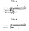
- According to a tenth aspect of the invention, there is provided a molded product manufacturing apparatus, which comprises: a forming mold which includes a minute uneven portion on a surface thereof; heating means which heats the forming mold; cooling means which cools the forming mold; and a resin coating device which fills a molten thermoplastic resin into the minute uneven portion. The resin coating device may include: a plasticizing part which plasticizes the thermoplastic resin; a resin reserving part which reserves the plasticized molten resin therein; and a discharge port which discharges the molten thermoplastic resin therefrom. The resin coating device may be movable in such a manner that the molten thermoplastic resin is discharged onto the minute uneven portion from above. The leading end portion of the discharge port may also be tapered. The discharge port may also include a pouring gate at least in one of its front and rear portions in a resin coating advancing direction.
- According to an eleventh aspect of the invention, the resin coating device is movable up to 6 degrees of freedom.
- According to a twelfth aspect of the invention, the resin reserving part is a reserving cylinder which, after it reserves once the molten resin poured therein, injects the molten resin in a predetermined feed rate.
- According to a thirteenth aspect of the invention, the reserving cylinder includes: a cylinder which reserves the molten resin, a piston which is located in the cylinder and injects the molten resin; and piston drive means which moves back and forth the piston. A clearance portion, through which the molten resin is allowed to pass, is formed between the cylinder and the piston. The apparatus is configured to: move the piston backward by using the piston drive means when the molten resin flows into the cylinder from the plasticizing part; reserve a given amount of the molten resin into the cylinder gradually from the leading end portion of the cylinder; and move the piston forwardly and inject the molten resin from the cylinder in the predetermined feed rate.
- According to a fourteenth aspect of the invention, the piston pushes and injects the molten resin in the predetermined feed rate.
- According to a fifteenth aspect of the invention, the apparatus further comprises a valve in a connecting flow passage interposed between the plasticizing part and the resin coating device, the valve opening and closing the connecting flow passage.
- According to a sixteenth aspect of the invention, the discharge port discharges the molten resin while moving in a state where the discharge port is supported by a highly rigid guide.
- According to a seventeenth aspect of the invention, the discharge port is supported on both sides thereof by at least one highly rigid guide located along the coating direction of the molten resin, and the highly rigid guide is fixed by two or more support members respectively located on the upstream and downstream sides of the coating direction of the molten resin.
- According to an eighteenth aspect of the invention, the above-mentioned discharge port is supported through a support member by a highly rigid guide located along the coating direction of the molten resin, and the highly rigid guide is fixed to the main body of the manufacturing apparatus with the resin coating device mounted thereon.
- According to a nineteenth aspect of the invention, the present molded product manufacturing apparatus further comprises moving means which moves a discharged resin receiving surface of the lower metal mold in a vertical direction. The moving means may adjust a distance between the leading end portion of a discharge part which discharges the molten resin and the discharged resin receiving surface of the lower metal mold. The moving means may be a platen of a pressing machine which mounts the lower metal mold thereon and presses the upper metal mold and the lower metal mold, and a distance between the discharge part and the discharged resin receiving surface of the lower metal mold may be adjusted by a vertical movement of the platen. Further, the moving means may be a vertically moving stage which is interposed between the lower metal mold and a platen of a pressing machine and presses the upper metal mold and the lower metal mold, the platen mounting the lower metal mold thereon, and a distance between the discharge part and the discharged resin receiving surface of the lower metal mold may be adjusted by a vertical movement of the vertically moving stage. Still further, the moving means may also be means for moving only the discharged resin receiving surface of the lower metal mold in the vertical direction, and a distance between the leading end portion of the die and the discharged resin receiving surface of the lower metal mold may be adjusted by a vertical movement of the means.
- According to the invention, there can be provided a method and apparatus for manufacturing a molded product having precise microstructure, high dimensional precision, low residual stress, low birefringence, high optical-transparency and excellent mechanical strength in a three dimensional geometry, thin wall and large-area by a very low molding pressure molding process.
-
- [Fig. 1] An explanatory view of a resin coating step included in a molded product manufacturing method according to the invention.
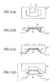
- [Fig. 2] Explanatory views of a process for manufacturing a molded product having a complicated three-dimensional shape using a method according to the invention.
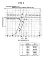
- [Fig. 3] An explanatory view to show how to determine the temperature of the cavity surface of a lower metal mold.
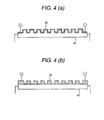
- [Fig. 4] Explanatory views of an example of means for heating a forming mold.
- [Fig. 5] An explanatory view of another example of means for heating a forming mold.
- [Fig. 6] Explanatory views of an example of a plasticizing part and a resin coating device.
- [Fig. 7] An explanatory view of another example of a plasticizing part and a resin coating device.
- [Fig. 8] Explanatory views of another example of a plasticizing part and a resin coating device.
- [Fig. 9] An explanatory view of another example of a plasticizing part and a resin coating device.
- [Fig. 10] An explanatory view of another example of a plasticizing part and a resin coating device.
- [Fig. 11] An explanatory schematic sectional view of an example of a molded product manufacturing apparatus according to the invention.
- [Fig. 12] An explanatory schematic sectional view of a reserving cylinder used in the invention.
- [Fig. 13] An explanatory view of a reserving cylinder used in the invention, showing a state where a piston is moved backward.
- [Fig. 14] An explanatory schematic sectional view of a molded product manufacturing apparatus according to the invention, showing an embodiment in which a valve is provided in a connecting flow passage between a resin melting part and a reserving cylinder.
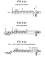
- [Fig. 15] An explanatory schematic sectional view of another embodiment of a molded product manufacturing apparatus according to the invention using a cylinder having an injection function as a resin injecting part.
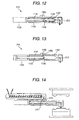
- [Fig. 16] An explanatory view of a resin coating device which can be used in the invention.
- [Fig. 17] Explanatory views of the shape of a discharge port which can be used in the invention.
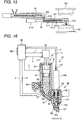
- [Fig. 18] Explanatory views of the shape of a discharge port which can be used in the invention.
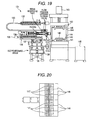
- [Fig. 19] An explanatory view of an example of a whole structure of a molded product manufacturing apparatus according to the invention.
- [Fig. 20] An explanatory view of the shape of a discharge port which can be used in the invention.
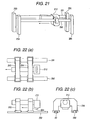
- [Fig. 21] An explanatory view of a step of discharging molten resin from a discharge part which moves while it is supported by a highly rigid guide.
- [Fig. 22] Explanatory views of another embodiment of the step of discharging molten resin from a discharge part which moves while it is supported by a highly rigid guide.
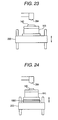
- [Fig. 23] An explanatory view of an example of means for moving a lower metal mold in the vertical direction.
- [Fig. 24] An explanatory view of another example of means for moving a lower metal mold in the vertical direction.
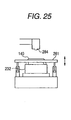
- [Fig. 25] An explanatory view of still another example of means for moving a lower metal mold in the vertical direction.
-
- 10:
- Minute uneven portion
- 11:
- Forming mold
- 12:
- Molten thermoplastic resin
- 13:
- Discharge port
- 21:
- Lower metal mold
- 23:
- Stamper
- 24:
- Upper metal mold
- 25:
- Molded product
- 61:
- Plasticizing part
- 65:
- Resin reserving part
- 131:
- Resin coating device
- 132:
- Plasticizing part
- 133:
- Flexible flow passage
- 140:
- Stamper
- 141:
- Lower metal mold
- 142:
- Upper metal mold
- 143:
- Precision vertical digital pressing machine
- 147:
- Six-divided discharge port
- 210:
- Reserving cylinder
- 232:
- Lower metal mold
- 1101:
- Cylinder
- 1102:
- Piston
- 1103:
- Piston drive means
- Now, description will be given below in more detail of the invention with reference to the accompanying drawings.
- Fig. 1 is an explanatory view of a coating step included in a method for manufacturing a molded product according to the invention. According to Fig. 1, onto a forming mold 11 (sectional view) having a minute
uneven portion 10 on the surface thereof, there is discharged a molten thermoplastic resin 12 (which is hereinafter referred to as molten resin as well) from a discharge port 13 (sectional view) formed in a resin coating device, whereby themolten resin 12 is filled into the minuteuneven portion 10. In a state shown in Fig. 1, while moving the resin coating device (not shown) in thearrow mark 14 direction and thus moving thedischarge port 13 as well in thearrow mark 14 direction, themolten resin 12 is discharged onto the minuteuneven portion 10 from above. - In a general injection molding method and a related method, the surface layer of resin filled into a cavity formed in a metal mold lowers in temperature immediately, whereby the viscosity of the resin starts to increase and a frozen layer starts to form on the surface of the resin. Therefore, in order to press the hard surface layer of the resin against the minute uneven portion to transcribe the shape of the minute uneven portion to the hard resin surface layer, a powerful pressing force is required.
- On the other hand, according to the invention, while moving the
discharge port 13 in thearrow mark 14 direction, themolten resin 12 is discharged onto the minuteuneven portion 10 from above. Therefore, themolten resin 12 reaches the inside of the minute uneven portion immediately. Accordingly, a decrease in the temperature of the resin is a very small and an increase in the viscosity of the resin is little. That is, themolten resin 12 reaches the inside of the minuteuneven portion 10 in an ideally low viscosity state. Since the filling of themolten resin 12 can be attained by discharging the molten resin from thedischarge port 13, such a powerful pressing force as in the related method is not necessary at all. In other words, in Fig. 1, if themolten resin 12 can be discharged from thedischarge port 13 in the arrow marks 15 directions, almost all of the shape of the minuteuneven portion 10 provided on the surface of the formingmold 11 can be transcribed to the molten resin only by the above-mentioned resin coating operation. - Also, the shorter the distance between the
discharge port 13 and formingmold 11 is (the smaller the thickness of the resin to be coated is) as well as the shorter the time necessary for the molten resin to reach the minuteuneven portion 10 is, the more the decreasing amount of the temperature of themolten resin 12 can be restricted. In a molded product manufacturing method according to the invention, themolten resin 12 is discharged onto the minuteuneven portion 10 from above while moving thedischarge port 13. Thus, as the distance between thedischarge port 13 and formingmold 11 is reduced and the time for themolten resin 12 to reach the minuteuneven portion 10 is shortened, the molten resin having a small amount of temperature decrease and a low degree of viscosity can be reached the inside of the minuteuneven portion 10 easily, and the shape of the minuteuneven portion 10 can be transcribed to the molten resin easily. Accordingly, a molded product manufacturing method according to the invention is very advantageous in manufacturing a thin wall molded product. - Further, according to the method of the invention, since the
molten resin 12 is filled into theuneven portion 10 from above while moving thedischarge port 13, the air of the inside of the minuteuneven portion 10 can be discharged in the arrow mark 16 direction. This eliminates a possibility of a case in which the air is confined in a space between the minuteuneven portion 10 andmolten resin 12 whereby obstructs the transcribe of the minute uneven shape to the molten resin. - Incidentally, the minute
uneven portion 10 according to the invention can be selected from a wide range of shapes which have a width or a diameter of 10 nm to 1 mm and a depth or a height of 10 nm to 1 mm. - Fig. 2 shows explanatory views of a process for manufacturing a molded product having a complicated three-dimensional shape by using a method according to the invention. In a state shown in Fig. 2, there are used two metal molds: an upper metal mold and a lower metal mold.
- Fig. 2(a) is a plan view of the forming
mold 11 placed on alower metal mold 21, and Fig. 2 (b) is a front view of the formingmold 11. In an embodiment shown in Fig. 2, the molten resin is coated one time in anarrow mark 22 direction shown in Fig. 2 (a) using a discharge port having a large width. Also, as part of the formingmold 11, astamper 23 having a minute uneven portion on the surface thereof is used. Thisstamper 23 is placed on the projectingportion 211 of thelower metal mold 21. Incidentally, in order that the molten resin is allowed to adhere to the inside of the minute uneven portion or to a cavity surface having a minute uneven portion, the formingmold 11 andstamper 23 are heated. In Fig. 2 (b), while moving thedischarge port 13 in thearrow mark 22 direction and along the shapes of thelower metal mold 21 andstamper 23, themolten thermoplastic resin 12 is coated in shape and thickness which are almost similar to those of a final shape of the molded product (resin coating step). Next, in Fig. 2 (c), anupper metal mold 24 is moved downward to press the coated thermoplastic resin and arrange the shape of a molded product (compressing step). Next, in Fig. 2(d), with the pressing force left applied, the thermoplastic resin is cooled and solidified (solidifying step). Then, the forming mold is opened and the moldedproduct 25 is removed from the forming mold. - Now, description will be given below in more detail of a molded product manufacturing method according to the invention.
- A specially preferred method according to the invention may include a series of the following steps (a) to (i):
-
- (a) As shown in Fig. 2, there are prepared two metal molds: a
lower metal mold 21 and anupper metal mold 24. The temperature of theupper metal mold 24 is raised up to a temperature where, in the compressing step, a frozen layer is not formed on the surface layer of themolten resin 12 contacted with the cavity surface of theupper metal mold 21 but themolten resin 12 can maintain such a softened state as to allow themolten resin 12 to be deformed after the shape of the cavity surface of theupper metal mold 24 under the pressing force applied. Further, the temperature of the cavity surface of thelower metal mold 21 is raised up to a temperature where themolten resin 12 is able to adhere to the inside of the minute uneven portion or to the cavity surface having a minute uneven portion (mold temperature raising step); - (b) After completion of raising the temperatures of the metal molds, in order that the
molten resin 12 can be filled into the whole of the minute uneven portion from thedischarge port 13, themolten resin 12 is discharged from thedischarge port 13 while moving thedischarge port 13, and themolten resin 12 is coated until it forms substantially the same shape as the final shape of a molded product (resin coating step); - (c) After completion of the resin coating step, the
upper metal mold 24 and thelower metal mold 21 are fitted with each other, and a pressing force generating device is used to press themolten resin 12 which exists between the cavity surface of thelower metal mold 21 and the cavity surface of theupper metal mold 24, thereby arranging the shape of themolten resin 12 to follow the shape of a closed space defined by and between the two closed cavities (compressing step); - (d) While the pressing force is left applied in order to compensate the shrinkage of the
molten resin 12 involved with the cooling of themolten resin 12, the thermoplastic resin is cooled down to a desired temperature and is solidified (solidifying step); - (e) After completion of the solidifying step, the
upper metal mold 24 and thelower metal mold 21 are opened by a minute amount in the range where their mutual fitted state can be maintained (mold unfastening step); - (f) One of the cavity surfaces of the
upper metal mold 24 and thelower metal mold 21 is released from the molded product using releasing means (not shown) installed on the forming mold (first releasing step); - (g) The other cavity surface than the cavity surface released in the (f) step is released from the molded product (second releasing step);
- (h) The forming mold is opened to such a distance that the molded product can be removed therefrom (mold opening step); and
- (i) The molded product is removed from the forming mold (molded product removing step).
- In the (a) step, as regards the temperature of the cavity surface of the lower metal mold, the "temperature where the
molten resin 12 to be discharged in the resin coating step is able to adhere to the inside of the minute uneven portion or to the cavity surface having a minute uneven portion" can be determined according to the conditions of the surface of the forming mold 11 (such as the surface roughness), the mother material of the forming mold 11 (such as the presence or absence of a treatment using a mold release agent), the kinds and temperature of the molten resin, the moving speed (resin coating speed) of the resin coating device, and the like. - Fig. 3 is an explanatory view to show how to determine the temperature of the cavity surface of the lower metal mold. In Fig. 3, a polymethyl methacrylate manufactured by Kuraray Co., Ltd. (Parapet GH1000S) is coated on a surface of a cavity made of stainless steel (SUS304) and finished with surface roughness of 1.6S while varying the resin temperature, cavity temperature and coating speed, thereby finding out the conditions that can achieve good resin coating. Incidentally, no mold releasing treatment is executed on the cavity surface at all. Fig. 3 shows that, provided that the target coating speed is set for 100 mm/s, when the resin temperature is 240°C, the temperature of the metal mold cavity may be set at a temperature of about 145°C or higher; and also, when the resin temperature is set for 250°C, the cavity temperature may be set at a temperature of 130°C or higher.
- In this manner, according to the invention, in the resin coating step, since the transcribe of the shape of the minute uneven portion to the molten resin is completed simultaneously with the coating of the molten resin, it is not necessary to maintain the forming mold at a very high temperature as disclosed in the related method. Therefore, the thermal degradation of the molten resin can be restricted, and also the dimensional variation of the molten resin due to the thermal expansion and shrinkage of the molten resin can be reduced. This can enhance the dimensional accuracy of the molded product, reduce the heating and cooling time of the forming mold and shorten the production time of the molded product. Therefore, the mold manufacturing method of the invention is very advantageous in that it can manufacture the molded product at a low cost.
- Incidentally, the raising of the temperature of the cavity of the upper metal mold may be completed before the forming mold is closed in the compressing step and the cavity is contacted with the upper surface of the coated molten resin. Therefore, the raising of the temperature of the upper metal mold may also be started, for example, during the resin coating step. The raising of the temperature of the cavity of the lower metal mold may be completed before the molten thermoplastic resin is contacted with the forming mold in the resin coating step.
- In the (b) step, generally, differently from, for example, an ultraviolet cure resin, the molten resin has a given level of viscosity (for example, 1000 Pa.s or more) even when it is in a melted state. Therefore, the
molten resin 12 can be coated until the coated molten resin has substantially the same shape as the final shape of the molded product. Incidentally, in the embodiment shown in Fig. 2, thedischarge port 13 is moved once for coating the molten resin once in thearrow mark 22 direction using a wide discharge port. However, the invention is not limited to this. For example, the molten resin may also be coated while reciprocating thedischarge port 13 two or more times. In this case, preferably, the resin coating device having thedischarge port 13 may be set so as to be able to move up to the six degrees of freedom, whereby, even when the formingmold 11 has a further complicated shape such as a three-dimensional shape, thedischarge port 13 is able to follow the shape of the formingmold 11. Incidentally, description will be given later of a resin coating device capable of such movement. Also, supply of the molten resin to the resin coating device may be completed before the resin coating is executed. Preferably, such molten resin supply may be executed in the step where the resin coating device is not in operation such as in the resin solidifying step or in the mold unfastening step. In this case, the molten resin can be coated immediately after completion of the metal mold temperature raising step. Therefore, the time (the cycle time) necessary for the molding operation can be reduced. - In the (c) step, the pressing pressure can be set for 10 MPa or less. The reason for this is as follows: that is, since the molten resin is coated in a shape substantially the same as the final shape of the molded product, there is no need to deform and move the coated molten resin by applying a high pressing force; and also, since the molten resin during compression is soft, the shape of the minute uneven portion can be transcribed to the molten resin with a very low pressing force. Therefore, even when the pressing force generating device is small, a product of a large area can be manufactured. This leads to the size reduction, space saving, energy saving and cost reduction of the molded product manufacturing apparatus. Also, since the molten resin within the cavity flows little during compression, phenomena, which give rise to optical distortion or bend, such as the polymer chain orientation involved with the flow of the molten resin are hard to occur in the compressing step as well. Further, in the compressing step and its following step such as the resin coating step, a high viscous thermoplastic resin cannot be forced to flow. As a result, when compared with a related injection molding method and the like, the molded product manufacturing method of the invention can provide a molded product which not only has excellent optical characteristics such as low residual stress, low birefringence and high optical-transparency, but also has high dimensional accuracy free from a bend. Further, the minute
uneven portion 10 of the formingmold 11 is hard to destroy, which leads to the extended life of the formingmold 11. Still further, since a powerful pressing force is not necessary, a forming mold made of zinc selenide (ZnSe) or silicon (Si) having no tolerance against pressure can be used. These materials are infrared ray transmission materials. Therefore, when these materials are used as the cavity surface and infrared rays are radiated onto the thermoplastic resin through such cavity surface as disclosed inJapanese Patent No. 3169786 - Incidentally, if a heating plate is inserted onto the coated molten resin to heat the top surface of the molten resin to thereby reduce the viscosity of the molten resin temporarily just before pressing the coated molten resin, and the molten resin is then pressed, the shape of the molded product can be arranged with further reduced pressure. The heating plate may be a plate on which an infrared lamp such as a halogen lamp mounted, or a plate which is heated by an ordinary heat transfer heater (this plate can heat the molten resin through the transfer of radiant heat from the plate). Further, the upper metal mold may be temporarily stopped just before the cavity surface of the upper metal mold is contacted with the resin, waiting for a rise in the temperature of the top surface of the resin due to the radiant heat from the cavity surface of the upper metal mold, and the molten resin may be pressed when the temperature of the molten resin top surface rises up to a desired temperature. According to any one of these examples of the heating means, since radiant heat is used, the heat transfer is approved even in the vacuum. Therefore, even when the below-mentioned pressure reducing/evacuating step is carried out, the heating of the molten resin can be achieved efficiently.
- Incidentally, a precision pressing force generating device, which is capable of not only opening and closing a metal mold by moving one of the upper and lower metal molds but also mold fastening and pressing the resin, can be realized by a vertical pressing machine or the like.
- In the below-mentioned pressure reducing/evacuating step, it is preferable to provide a function to detect the position of the forming mold accurately and stop temporarily the mold closing operation in a state where a minute clearance intervenes between the upper metal mold cavity surface and the molten resin top surface. In the solidifying step, it is preferable to close the forming mold by an amount corresponding to the volume shrinkage of the molded product (that is, high-precision pressing force control may be made) while allowing the pressing force to follow the set value with high accuracy in order to compensate the volume shrinkage of the molded product. Further, in the below-mentioned mold unfastening step, it is necessary to open the forming mold slightly only by a stroke smaller than the thickness of the molded product. Accordingly, the positioning and speed control of the forming mold when moving the forming mold as well as pressure control during the mold clamping (during compression) must be executed with relatively high accuracy. Therefore, it is preferred to employ a pressing force generating device which, as a drive system, uses a mechanism easy to achieve a precise control such as a servo motor.
- In the (c) step, more preferably, in a state where the
upper metal mold 24 and thelower metal mold 21 are fitted with each other and a minute clearance intervenes between the cavity surface of theupper metal mold 24 and the top surface of the thermoplastic resin, the air in the minute clearance may be sucked to thereby provide a pressure reduced state or a substantially vacuum state and, after then, the cavity surface of theupper metal mold 24 and the top surface of the thermoplastic resin may be contacted with each other and the pressing force may be then applied to the resin. This can remove the air intervening between the molten thermoplastic resin and the cavity of theupper metal mold 24, which can in turn avoid poor transcription possibly caused by the air trapped and confined in such minute clearance. - The air suction port may be formed specially in the cavity surface. However, in the case of a forming mold including a mechanical ejector, for example, the air can be sucked from a clearance in the cavity formed due to the sliding motion of the ejector. As the sucking means, a well-known vacuum pump or the like may be used. The present pressure reducing/evacuating step can be executed with more efficiency in a forming mold composed of upper and lower metal molds and structured such that the cavities of the upper and lower metal molds have male and female shapes and, when the upper and lower metal molds are fitted with each other in the mold closing step, the male side cavity is inserted into the female side cavity by a slight amount to thereby form a closed space. The timing for pressure reducing and providing a substantially vacuum state may preferably be set in the time when, after formation of the closed space, a minute clearance intervenes between the cavity surface of the upper metal mold and the top surface of the molten resin. The reason for this is that, after the cavity surface and molten resin are contacted with each other and the air is confined between them, the effect of the air suction cannot be obtained if no suction port formed in the air closed range. In order to execute the operation of the pressure reducing/evacuating step at a proper timing, for example, by detecting the position of the forming mold from the pressing force generating device, the suction means may be started when the forming mold reaches a desired position, and the suction means may be stopped at a position where the cavity surface of the upper metal mold is perfectly contacted with the top surface of the molten resin. Other various embodiments are also possible. For example, there may be carried out the following operation: start of the suction means → stop of the mold closing operation → suction of the air for a given time under control using a timer → resumption of the mold closing operation. Also, there may be provided means for detecting the pressure in the cavity. After the air is sucked, at a time when the pressure of the cavity is reduced down to a desired pressure, the mold closing operation may be resumed.
- In the (d) step, since the molded product is cooled until the temperature of the molded product reaches a desired temperature while the pressing is left applied, it is possible to prevent defect such as a sink mark possibly caused by the volume shrinkage of the resin, thereby being able to obtain a high-quality molded product which has high dimensional accuracy.
- In the (e) step, the amount of opening of the forming mold may be larger than the height or depth of the minute uneven portion.
- In the (f) to (i) steps, as the installed releasing device on the forming mold, there can be used a mechanical ejector or an air blow mechanism respectively embedded in the forming mold. The entire surface of the molded product can be released from the cavity surface by using such releasing device. When a minute releasing portion is formed between the molded product and cavity surface by the pressing force of the mechanical ejector or by a discharge pressure to be applied to fluid discharged from a fluid discharge port, the fluid enters the releasing portion. Then, the discharge pressure propagates to promote the next releasing, thereby the releasing portion is gradually expanded. This phenomenon occurs successively, with the result that the entire surface of the molded product is released from the cavity surface. In the above-mentioned description, more preferably, there may be employed the well-known air blow mechanism, that is, a mechanism in which a discharge port for discharging the fluid such as the air is formed in the cavity surface (preferably, in the center of the molded product), and the fluid is discharged from the discharge port. In the mechanical ejector system, because the mechanical ejector can push (apply an exfoliative force) only a local portion of the surface of the molded product, there is raised a problem that, if the molded product becomes thin in the thickness, the molded product can be broken or destroyed before the surface of the molded product is released from the cavity surface. As described above, according to the method in which the fluid with the pressure applied thereto is fed into the releasing portion, the pressing force can be applied to the whole of the releasing portion to thereby generate the releasing force uniformly. Accordingly, it is easy to release a thin wall molded product. Next, the forming mold is opened to such a distance that the molded product can be removed therefrom, and the molded product is then removed from the forming mold.
- The thermoplastic resin to be used in the invention is not limited to specific resin but there can be used various kinds of resin. For example, polymethyl methacrylate (PMMA), polycarbonate (PC), cyclo olefin polymer (COP), polyethylene telephtalate (PET), polybutylene telephtalate (PBT), polyarylate (PAR), polyimide (PI), polypropylene (PP), polyamide (PA), polyethylene (PE), polyacetal (POM), ethylene vinyl acetate copolymerization resin (EVA), acryl nitrile butadiene styrene (ABS), poly vinyl chloride (PVC), poly phenylene oxide (PPO), or mixtures of these resin can be used. Also, there may also be employed the thermoplastic resin that is produced specially so as to match the desired performance of a molded product.
- Incidentally, as for the thermoplastic resin, there can be added various kinds of well-known additives as the need arises. For example, various fillers such as glass fibers or carbon, heat resisting stabilizers, weatherproof stabilizers, antistatic agents, slip agents, anti-blocking agents, anti-misting agents, lubricants, dyes, pigments, natural oil, synthetic oil, wax, or the like, can be added.
- According to a molded product manufacturing method of the invention, there can be obtained a molded product which has a small thickness in the range of 50 µm to 5 mm and a large area with a side length of the molded product exceeding 1000 times the thickness of the molded product.
- Next, description will be given below of a molded product manufacturing apparatus according to the invention.
- A molded product manufacturing apparatus according to the invention is characterized in that it comprises a forming mold which includes a minute uneven portion on a surface thereof; heating means which heats the forming mold; cooling means which cools the forming mold; and a resin coating device which fills a molten thermoplastic resin into the minute uneven portion, wherein the resin coating device includes: a plasticizing part which plasticizes a thermoplastic resin; a resin reserving part which reserves the plasticized molten resin therein; and a discharge port which discharges the molten thermoplastic resin therefrom, and wherein the resin coating device is movable in such a manner that the molten thermoplastic resin is discharged onto the minute uneven portion from above.
- The forming mold including a minute uneven portion on the surface thereof may be set in any portion of the cavities of the upper and lower metal molds so as to match the required performance of the molded product, as described above. Preferably, it may be set in the cavity surface of the lower metal mold onto which the molten resin is precision coated by the resin coating device, whereby the shape of the minute uneven portion can be transcribed under low pressure and with high accuracy. According to the invention, a minute uneven portion may be engraved on the surface of a stamper using a semiconductor process such as a photolithography method, an electroplating method, and an ion etching method, and the formed minute uneven portion may be set within a forming mold. As the material of the stamper, there can be used nickel (or a nickel alloy), silicone, glass, or the like. The stamper may be made of only such material. Further, there may be formed a minute uneven portion made of a nickel or the like on a plate-shaped mother member (a silicone base plate) having a thickness of, for example, several tens µm to several mm. Besides this, a minute uneven portion may also be formed directly on the cavity surface of the main body of the forming mold. The section shape of the uneven portion is basically rectangular but it may also be tapered (trapezoidal), triangular, semi-circular, or semi-elliptic.
- As the means for heating and/or cooling the cavity surfaces of the upper and lower metal molds, there are available various methods.
- As the heating means, for example, there are available the following methods.
-
- (1) A method for heating the cavity surface by passing a temperature controlled heat medium such as water (hot water) or oil through a flow passage formed in the forming mold for the heat medium.
-
- (2) A method for heating the cavity surface by mounting or inserting an electric heater such as a plate heater or a cartridge heater on the forming mold.
-
- (3) A method for heating the cavity surface of the forming mold by radiating infrared rays onto the cavity surface using a device for radiating infrared rays such as a halogen lamp or a far infrared heater.
-
- (4) A method for heating the cavity surface by using induced heat.
-
- (5) A method in which, as shown in Fig. 4, a thin
conductive membrane 42 is formed on the surface of the cavitymain body 41 made of an electric insulator, and theconductive membrane 42 is electrically energized so as to generate heat in theconductive membrane 42. In this case, the uneven portion may be coated with the conductive membrane 42 (Fig. 4(a)), or the uneven portion itself may be formed of the conductive membrane 42 (Fig. 4(b)). - The above methods are examples of the means for heating the whole of the cavity surface (or the metal mold). Further, as shown in Fig. 5, heating means 53 such as an infrared lamp may be provided in the vicinity of the
discharge port 52 of aresin coating device 51, and the molten resin may be coated while locally heating the surface of thecavity 54 just before the molten resin is coated so as to raise the temperature of thecavity 54 surface up to a temperature where the molten resin is able to adhere to thecavity 54 surface. Incidentally, in this case, the moving direction of the resin coating device is a direction shown by thearrow mark 55, areference numeral 56 designates the portion that is heated locally by the heating means 53 such as an infrared lamp, and areference numeral 57 stands for the coated molten resin. According to the states respectively shown in Figs. 4 and 5, the temperature of the whole of the cavity can be left low. Therefore, the thermal degradation of the resin can be restricted, and the time and energy required for cooling and solidifying the molded product can be reduced. - Next, as cooling means, there are available the following methods.
-
- (1) A method for cooling the cavity surface by flowing temperature conditioned water through a medium flow passage formed in a metal mold.
-
- (2) A method for cooling the cavity surface by flowing the air through a pipe conduit provided in a metal mold.
-
- (3) A method for cooling the cavity surface by spraying the air or a mist, which is a mixture of volatile (changeable in phase from liquid to gas on the cavity surface) liquid and a gaseous body, onto the cavity surface.
-
- (4) A method for cooling the cavity surface by carrying and discharging heat within a metal mold to the outside of the metal mold by using a heat pipe.
-
- (5) A method for cooling the cavity surface by absorbing heat within a metal mold or heat on the cavity surface using an electric cooling device such as a Peltier element.
- The above-mentioned heating and cooling means may be used in proper combination according to cases.
- The plasticizing part may have a function to be able to plasticize resin into melted state and a function to be able to supply the thus molten resin to the resin reserving part of the resin coating device. As the plasticizing part, for example, there may also be used a single screw extruder or a twin screw extruder.
- Also, a resin coating device according to the invention may also be structured such that, as shown in Fig. 6(a), a mounting and removing
mechanisms plasticizing part 61 and aresin coating device 62, respectively; theplasticizing part 61 is structured to be mountable onto and removable from theresin coating device 62;valves plasticizing part 61 andresin coating device 62, respectively; in a state where theplasticizing part 61 andresin coating device 62 are connected together, both valves are opened to thereby allow the flow passages for molten resin to communicate with each other; the molten resin is fed from theplasticizing part 61 into theresin reserving part 65 of theresin coating device 62; and, at the time when a given amount of molten resin is reserved, thevalves plasticizing part 61 is removed as shown in Fig. 6(b). Also, there may be employed a structure as shown in Fig. 7: that is, theplasticizing part 61 andresin coating device 62 are connected together by aflexible flow passage 66 and thus the molten resin can be fed into theresin coating device 62 from theplasticizing part 61. - Instead of the above structures, as in an inline-type injection molding machine, the resin reserving part may have the function of the plasticizing part as well. For example, as shown in Figs. 8(a) and 8(b), an inline-type
injection molding machine 71 includes aresin reserving part 72 and ascrew 73 which can be rotated and can be moved in the forward and backward directions. When thescrew 73 is rotated in thearrow mark 74 direction, thescrew 73 moves in the backward direction and a resin is plasticized while moving in thearrow mark 75 direction. After completion of the plasticization of the resin, as shown in Fig. 8(c), the molten resin reserved within theresin reserving part 72 is discharged from adischarge port 77. - Also, as in a pre-plasticizing type injection molding machine shown in Fig. 9, the resin coating device may be composed of a
plasticizing cylinder 82 including ascrew 81 and aninjection cylinder 84 including apiston 83 movable in the forward and backward directions. In this device, molten resin plasticized in theplasticizing cylinder 82 may be fed to and reserved in the leading end portion of theinjection cylinder 84. After then, thepiston 83 may be moved forward so as to discharge the molten resin from adischarge port 85. Incidentally,reference numeral 86 designates a valve, and the molten resin can be discharged from thedischarge port 85 by opening thevalve 86. - Other embodiments are also possible. For example, as shown in Fig. 10, molten resin transport means such as a screw or a piston may be provided in a reactive pot or a
reactor 87, and the may introduce the plasticized resin into thecylinder 89 of the above-mentioned injection molding machine after the resin is plasticized within thereactor 87. - The temperature for plasticizing the resin may be a temperature where the resin material can be melted.
- As another embodiment, as shown in Fig. 11, it is also possible to employ a structure which is mainly composed of a
plasticizing part 61 for melting and transporting a thermoplastic resin, aresin reserving part 65 connected to theplasticizing part 61 for injecting a poured molten resin (the detailed structure of which will be discussed later) in a predetermined feed rate, and adischarge part 212 for discharging the molten resin fed out from theresin reserving part 65 onto a discharged resin receiving surface from above. - The
resin reserving part 65 may preferably be composed of a reserving cylinder which reserves once therein the poured molten resin and injects the molten resin in the predetermined feed rate. - Fig. 12 is an explanatory schematic sectional view of a reserving cylinder used in the present invention.
- In Fig. 12, a reserving
cylinder 210 comprises acylinder 1101 having a cylindrical shape as a whole for reserving the molten resin therein, apiston 1102 provided within thecylinder 1101 for push and inject the molten resin in the predetermined feed rate, and piston drive means 1103 for moving thepiston 1102 back and forth. Also, the reservingcylinder 210 further includes, in the outer peripheral portion thereof, means for heating and cooling the surface of the storing cylinder. As shown in Fig. 12, aclearance part 1104 through which the molten resin can pass is formed between the cylinder 11010 andpiston 1102. When the molten resin flows from theplasticizing part 61 through anentrance port 1105, the molten resin is allowed to flow through theclearance part 1104 in the arrow mark direction. By setting the flow speed of the molten resin at a rather fast speed, the stagnation of the molten resin can be prevented. The size of theclearance part 1104 maybe determined properly depending on the kinds of molten resin used, for example, it may be several mm or so, and, specifically, it may be in the range of 0.5 to 5 mm. - Simultaneously with the inflow of the molten resin, the piston drive means 1103 is put to work so as to move the
piston 1102 backward as shown in Fig. 13. Owing to this operation, the molten resin is gradually reserved in thecylinder 1101 starting from the leading end portion (discharge port side) of thecylinder 1101. When reserve of a predetermined amount of molten resin is completed, the piston drive means 1103 is operated to move thepiston 1102 forward by a given distance, thereby being able to send out the molten resin at a predetermined feed rate. Incidentally, the position control of thepiston 1102 must be made with relatively high accuracy. Therefore, as the piston drive means 1108, there may be used a pressing force generating device such as a servo motor having a mechanism easy to secure accuracy. - According to the above-mentioned structure, the molten resin, which has flowed in first, is first fed and discharged out to the discharge part. This makes it possible to prevent the molten resin from degradation (transparent resin turns yellow (burnt) or dark brown (black spots)) due to the long residence time of the molten resin. Further, since the resin melting part and reserving
cylinder 210 are connected together by a short path, the residence time of the molten resin can be reduced, thereby being able to prevent the occurrence of the thermal degradation of the molten resin more effectively. Incidentally, if a molded product is manufactured using the thermally degraded molten resin, there may be raised a problem that a desired optical transmittance or a desired refraction coefficient cannot be obtained when the molded product is used in an optical product. - Suppose the
cylinder 1101 andpiston 1102 are contacted with each other, there can be produced metal powder due to the friction between the two metal members, thereby raising a fear that the metal powder can have ill influences on the product. However, in the reservingcylinder 210 according to the invention, since the clearance part is formed 1104 between thecylinder 1101 andpiston 1102, there is no possibility that such metal powder can be produced. - Also, as shown in Figs. 12 and 13, in the reserving
cylinder 210, there is provided a back flowpreventive part 1106 which prevents the molten resin from flowing therethrough in order to prevent the molten resin, which has first flown into thecylinder 1101, from flowing into the opposite direction (toward the piston drive means 1103 side) to the leading end portion of thecylinder 1101. Incidentally, the back flowpreventive part 1106 has a curved surface extending from theentrance port 1105 of the molten resin in the direction of the leading end portion of thecylinder 1101 such that the molten resin can be easily guided to the leading end portion of thecylinder 1101. - Further, according to the invention, preferably, a valve, which is capable to open and close the connecting flow passage, is provided in the connecting flow passage between the plasticizing
part 61 and reservingcylinder 210. - Fig. 14 is a schematic sectional view of a molded product manufacturing apparatus, explaining a structure in which a valve is located in a connecting flow passage formed between the plasticizing
part 61 and reservingcylinder 210. The molded product manufacturing apparatus shown in Fig. 14 is almost similar in structure to the molded product manufacturing apparatus shown in Fig. 11. However, it is different from the manufacturing apparatus shown in Fig. 11 in that avalve 215 is located in a connectingflow passage 214 between the plasticizingpart 61 and reservingcylinder 61. As described above, after completion of the reserve of the molten resin within thecylinder 1101 of the reservingcylinder 210, the piston drive means 1103 is operated to move thepiston 1102 forward by a given distance so as to inject the molten resin into thedischarge part 212 in the predetermined feed rate. Here, the injecting amount of the molten resin is determined by the volume of the molded product. Therefore, in order to manufacture the molded product with high precision, it is necessary to reserve a controlled amount of the molten resin into thecylinder 1101 and also inject the controlled amount of the molten resin from thecylinder 1101. However, if a pressure difference occurs between the plasticizingpart 61 and reserving cylinder 210 (normally, during the resin reserving time, the molten resin pressure of theplasticizing part 61 rises), the molten resin within theplasticizing part 61 is allowed to flow into thecylinder 1101 more than necessary and thus the amount of the molten resin flowing into thecylinder 1101 exceeds the predetermined amount. In such case, the excessive amount of the molten resin is reserved in thecylinder 1101, which makes it difficult to manufacture the molded product with high precision. To solve this problem, thevalve 215 is located in the connectingflow passage 214 between the plasticizingpart 61 and reservingcylinder 210, and the valve is closed to thereby cut off the flow of the molten resin from theplasticizing part 61 into thecylinder 1101 at the time when the reserve of the molten resin into thecylinder 1101 is completed. This makes it possible to reserve a predetermined amount of the molten resin. - Further, after completion of the reserve of the molten resin, the piston drive means 1103 is operated to move the
piston 1102 forward by a given distance to thereby inject the molten resin into thedischarge part 212 in the predetermined feed rate. In this case as well, preferably, thevalve 215 may be left closed. By leaving thevalve 215 closed, the injecting pressure of the molten resin due to the forward movement of thepiston 1102 can be prevented from escaping to theplasticizing part 61 through the connectingflow passage 214. This makes it possible to inject the molten resin to thedischarge part 212 in the predetermined feed rate. Accordingly, the molded product can be manufactured with high precision. - As the
valve 215, there can be used any type of valve, provided that it can cut off the flow passage (connecting flow passage 214) of the molten resin and can control the inflow and outflow of the molten resin. For example, a well-known rotary valve can be used. - The
discharge part 212 for discharging the molten resin fed out from theplasticizing part 61 onto the discharged surface from above is not limited to a specific discharge part.
Preferably, there may be used such a discharge part that can deform the molten resin into a sheet (membrane) shape with high precision before it is discharged. Normally, thedischarge part 212 is directly connected with theresin reserving part 65. - In the above-mentioned embodiment, as an example of the
plasticizing part 61, description has been given of the reservingcylinder 210 structured such that it once reserves the molten resin having flown therein and then injects the thus reserved molten resin in the predetermined feed rate. However, the invention is not limited to this. For example, as theplasticizing part 61, instead of the reservingcylinder 210, there can be used a cylinder having an injection function. - Fig. 15 is an explanatory schematic sectional view of another embodiment of a molded product manufacturing apparatus according to the invention which uses a cylinder having an injection function as a resin injecting part.
- The molded product manufacturing apparatus shown in Fig. 15, similarly to Fig. 11, is mainly composed of a
plasticizing part 61 for melting a thermoplastic resin and transporting the molten resin, aresin reserving part 65 connected to theplasticizing part 61 for injecting the molten resin poured therein and adischarge part 212 for discharging the molten resin fed out from theresin reserving part 65 onto a discharged resin receiving surface from above. According to the present embodiment, as the resin reserving part, there is used acylinder 211 having an injection function. As thecylinder 211, there can be used a cylinder which is produced for an injection molding machine; for example, a cylinder the whole of which has a cylindrical shape and also which includes a penetrationinner hole 1112 with ascrew 1111 contacted with the inner surface thereof. Also, thecylinder 211 further includes two or more heaters which are respectively mounted on the outer peripheral surface thereof. Thescrew 1111 is structured such that it can be rotated as well as can be moved back and forth by drive means 1113. - The molten resin from the
plasticizing part 61 flows into thecylinder 211 from anentrance port 1114. The molten resin is then fed in the direction of the leading end portion of thecylinder 211 owing to the rotation of thescrew 1111. After a given amount of the molten resin is reserved in the leading end portion of thecylinder 211, thescrew 1111 is moved forward according to a normally used method to thereby inject the molten resin to thedischarge part 212 in the predetermined feed rate. Incidentally, similarly to the embodiment shown in Fig. 14, it may be preferable to provide avalve 215 in a connectingflow passage 214 between the plasticizingpart 61 andcylinder 211, and close thevalve 215 when the reserve of the molten resin into thecylinder 211 is completed so as to cut off the flow of the molten resin from the resin reserving part. This provides an effect that the reserve of the molten resin in the predetermined feed rate is possible. Further, after the reserve of the molten resin is completed, the molten resin is fed out to thedischarge part 212 by the injection function of thecylinder 211 in the predetermined feed rate. Preferably, thevalve 215 may be left closed at this time as well. This not only can prevent the injecting pressure of the molten resin from escaping through the connectingflow passage 214 to theplasticizing part 61, but also makes it possible to inject the molten resin to thedischarge part 212 in the predetermined feed rate. Accordingly, the molded product can be manufactured with high precision. - As an embodiment of a resin coating device which is different from the above-mentioned embodiment, there can be pointed out a resin coating device which is disclosed in, for example,
JP-A-2004-121986 - Fig. 16 is an explanatory view of an example of such resin coating device.
- In Fig. 16, a resin coating device A1 is generally composed of a
cylinder 91 functioning as a resin reserving part, and aresin coating part 92 which belongs to thecylinder 91 and is formed substantially integral with thecylinder 91. In the inside of thecylinder 91, there is located apiston 94 which can be driven in a vertical direction in Fig. 16 by apiston drive device 93. When thepiston 94 is driven downward, the molten resin is pushed out through theresin coating part 92 to a forming mold. In the side portion of thecylinder 91, a resin supply passage 95 is opened up. In correspondence to the resin supply passage 95, there is provided arotary valve 96 which is an example of means for opening and closing the resin supply passage 95. Incidentally, although not shown in Fig. 16, the above-mentioned plasticizing part for melting solid-state resin is provided in the present resin coating device A1, and the plasticized molten resin can be supplied through therotary valve 96 to thecylinder 91. The push-out amount of the molten resin in thecylinder 91 is controlled very carefully depending on the drive speed of thepiston 94. On the outer peripheral portion of thecylinder 91 structured in the above-mentioned manner, there are provided two ormore heaters heaters control unit 98. - The lower end portion of the
cylinder 91 is narrowed in a tapered manner to provide aresin passage 99 which is continuous with theresin coating part 92. Theresin coating part 92 is composed of aresin adjusting portion 100 for allowing the molten resin to flow therethrough or for reserving the molten resin temporarily therein and aspatula portion 101 which is situated at the lower end of theresin adjusting portion 100. The lower end portion of thespatula portion 101 is cut off obliquely and can be thereby moved at a given speed in the arrow mark D direction. Since theinclined surface 102 of thespatula portion 101 is situated ahead in a moving direction, adischarge port 103 which functions as the exit of the molten resin is opened up in theinclined surface 102. In the present embodiment, thedischarge port 103 is in communication with theresin adjusting portion 100. In thedischarge port 103, there is located aneedle 104 the leading end portion of which is reduced in diameter in a tapered manner. The upper end portion of theneedle 104 is connected to the output shaft of aneedle drive device 105 and is sealed by packingglands needle 104 is driven downward properly by theneedle drive device 105, degrees of opening of thedischarge port 103 can be adjusted. Incidentally, on the outer peripheral portion of thespatula portion 101 as well, there is located aheater 107 which functions as heat generating means. The amount of heat to be generated by theheater 107 is also controlled in the above-mentioned manner. - The
control unit 98 also includes setting means 108 for setting the temperatures and pressures of the molten resin within thecylinder 91 andresin coating part 92, the driving speed of thepiston 94, the degrees of opening of thedischarge port 103, the moving speed of the resin coating device A1 in the resin coating operation thereof, and the like. Thecontrol unit 98, which has the above-mentioned function and includes the setting means 108, is connected by a signal line a to aresin pressure sensor 109 for measuring the pressure of the molten resin within thecylinder 91, is connected by a signal line b to atemperature sensor 110 composed of a thermocouple and the like for detecting the temperature of the molten resin, and is connected by a signal line c to aspeed sensor 111 for detecting the driving speed of thepiston 94, respectively. - Also, the
control unit 98 is also connected to a needle position detectsensor 112 by a signal line d. Various kinds of measurement values measured by thesesensors 109 to 112 are respectively input to thecontrol unit 98 through their associated signal lines a to d, and are operated by thecontrol unit 98. The manipulated value of thecontrol unit 98 are respectively applied to theheaters piston drive device 93 through a power line i, and similarly to theneedle drive device 105 through a power line j. - Next, description will be given below of a resin coating method using the molten resin coating device A1 according to the above-mentioned embodiment. The temperatures of the
heaters piston 94, the pressure of the molten resin, the opening degrees of thedischarge port 103 and the like are set in thecontrol unit 98 by the setting means. Therotary valve 96 is opened and the plasticized resin is supplied to thecylinder 91. Next, a resin coating operation is started. Thepiston 94 is driven, whereby the molten resin in thecylinder 91 maintained at a set temperature is fed to theresin adjusting portion 100 of theresin coating part 92 by a given amount. The molten resin is then pushed up onto the forming mold by theneedle 104 from thedischarge port 103 kept at a given opening degree. Simultaneously with this, the spatula portion of the resin coating device A1 is moved in an arrow mark D direction. The thus pushed-out molten resin is extended onto the forming mold by thespatula portion 101. This completes the resin coating operation. - The discharge amount of the resin from the discharge port is controlled according to the coating width, coating thickness and coating speed of the molten resin (the speed at which the discharge port of the resin coating device moves on the forming mold) to the forming mold.
- The discharge port, preferably, may have such a shape that the molten resin can be discharged in a slit manner in a direction substantially perpendicular to the resin coating direction. The discharge port is composed of one or more discharge ports which are connected together in a direction substantially perpendicular to the resin coating direction. In the case where two or more discharge ports are connected together, it is preferable to change a resin discharge width arbitrarily at the width pitches of the respective discharge ports by opening or closing switch valves respectively provided in the resin flow passages of the respective discharge ports. The widths and shapes of the respective discharge ports may be changed freely according to the shapes of the forming molds. Also, the number of discharge ports connected may be changed to thereby change the discharge width. Further, as shown in Figs. 17 (a) and 17 (b), there may be additionally formed in the discharge port a
gate 120 for changing the discharge width and the resin may be coated while changing the position of thegate 120 successively so as to provide a desired resin coated shape. - The discharge port spatula portion may have such a shape that a pouring gate in the obliquely cut-off lower end portion thereof is provided on the rear side in the resin coating advancing direction as shown in Fig. 18(a), or may have such a shape that two pouring gates are provided on both back and front sides in the resin coating advancing direction as shown in Fig. 18 (b). To fill the molten resin into the minute uneven portion more efficiently using the discharge pressure, it is suitable to employ the latter shape in which the pouring gates are provided on both back and front sides in the resin coating advancing direction. Further, the discharge port spatula may also have such a shape that the leading end portion of the discharge port is formed in a tapered manner as shown in Fig. 18(c).
- Incidentally, it is more preferable to provide pouring gates in the discharge port on the right and left sides as well in the advancing direction, whereby four pouring gates may be provided respectively on the right and left sides as well as on the back and front sides in the discharge ports. In this manner, there may be formed a substantially closed space between the leading end of the spatula portion of the discharge port and cavity surface, thereby providing a shape which makes it difficult for the discharge pressure to escape.
- Fig. 19 is an explanatory view of an embodiment of the whole structure of a molded product manufacturing apparatus according to the invention. According to the embodiment shown in Fig. 19, a
resin coating device 131 is structured such that aplasticizing part 132 is released from theresin coating device 131, aflexible flow passage 133 connects theresin coating device 131 and theplasticizing part 132, and the molten resin is fed to the to theresin coating device 131 from theplasticizing part 132 through the connecting flow passage 133 (see Fig. 7). In theresin coating device 131, in order that it can be moved in the translating direction of the XYZ axes, there are provided a table 134 movable in the X axis direction (in the translating direction) and adrive motor 135 for driving the table 134, a table 136 movable in the Y axis direction and adrive motor 137 for driving the table 136, and a table 138 movable in the Z axis direction and adrive motor 139 for driving the table 138. As a forming plate, there is used astamper 140 including a minute uneven portion on the surface thereof, while thestamper 140 is placed on alower metal mold 141. Thislower metal mold 141 and anupper metal mold 142 are respectively mounted on a precision vertical digitalpressing machine 143, while each of them includes metal mold heating means 144 composed of an electric heater and metal mold cooling means composed of temperature controlled water. Also, means for releasing a molded product from the mold is composed of a well-known mechanical ejector or air blower using mold releasing means drivedevice 146. Incidentally, theresin coating device 131 includes six-divideddischarge ports 147 as shown in Fig. 20. The discharge quantities of therespective discharge ports 147 can be further adjusted by their associated flow passage opening/closing valve driving cylinders 148 (in Fig. 19, they are shown by the arrow mark XV). - Incidentally, the control of the temperature of the flexible flow passage, the control of the temperatures of the cylinder and discharge ports of the resin coating device, the control of the temperatures of the upper and lower metal molds, the opening and closing control of the valves for opening and closing the flexible flow passage and the resin flow passage of the resin coating device, the opening and closing control of the valves for opening and closing the multiple divided discharge ports, the control of the operation for moving the XYZ axes tables and pistons of the resin coating device at desired positions and speed, the control of the mold opening and closing operation (the position, speed and pressure) of the digital pressing machine, and similar control are respectively executed by a control unit (not shown).
- Incidentally, the resin coating device according to the embodiment shown in Fig. 19 is mounted on the XYZ table and has a cantilevered structure that the rear side of the resin coating device is fastened to a stage. Preferably, in the resin coating step, in order to prevent the
discharge part 212 from being flexed in the vertical direction due to the reaction against the discharge of the molten resin, thedischarge part 212 of the resin coating device may be moved while it is being supported by a highly rigid guide and may discharge the molten resin. - Fig. 21 is an explanatory view of a step of discharging the molten resin from the
discharge part 212 to be moved while it is being supported by a highly rigid guide. - In Fig. 21, the two sides of the
discharge part 212 are supported by at least two highlyrigid guides rigid guides more support members discharge part 212 moves in an arrow mark direction along the highlyrigid guides discharge part 212 being flexed in the vertical direction due to the reaction against the discharge of the molten resin, thedischarge part 212 can discharge the molten resin in a preset thickness. - The highly
rigid guides discharge part 212 from being flexed in the vertical direction due to the reaction against the discharge of the molten resin. For example, they may be made of stainless steel. - As a method for supporting the
discharge part 212, besides the method for supporting thedischarge part 212 by at least two highlyrigid guides discharge part 212 is supported by two guide rails. Thedischarge part 212 may be supported by at least one guide rail using a guide rail having a wide width. Specifically, thedischarge part 212 is moved while it is being supported by two highly rigid guides (guide rails) 291 and 292 using a linear guide bearing. In Fig. 22, thedischarge part 212 is supported by two highlyrigid guides support members rigid guides - Incidentally, in the embodiment shown in Fig. 19, the
lower metal mold 141 includes a projecting portion, and thestamper 140, which includes a minute uneven portion, is mounted on the surface of the projecting portion. Thus, in order to move the leadingend lip portion 284 of thedischarge part 212 along the shapes of thelower metal mold 141 andstamper 140, preferably, there may be provided moving means for moving thelower metal mold 141 in a vertical direction, and the distance between the leadingend lip portion 284 of thedischarge part 212 andstamper 140 may be adjusted. When compared with a large-scale apparatus structure for moving the discharge part, plasticizing part and resin coating device in the vertical direction, according to the present embodiment, a role for the vertical movement is played by the forming mold. Thus, a fast vertical operation is possible, the moving speed of thedischarge part 212 can be enhanced, thereby being able to improve the productivity of the present molded product manufacturing apparatus. - Specifically, there can be employed such a method as shown in Fig. 23. In this method, the
lower metal mold 141 is set in such a manner as shown in Fig. 23. A platen of apressing machine 200 having the pressurizing function of a pair of upper and lower metal molds is used as moving means. By moving theplaten 200 in the vertical direction, the distance between the leadingend lip portion 284 of thedischarge part 212 andstamper 140 can be adjusted. - Also, there can also be employed such a method as shown in Fig. 24. In this method, between a platen of a
pressing machine 200 functioning as moving means and alower metal mold 141, there is interposed a verticallymovable stage 1001, and a distance between the leadingend lip portion 284 of the die andstamper 140 can be adjusted by moving the verticallymovable stage 1001 in the vertical direction. - Further, there can also be employed such a method as shown in Fig. 25. In this method, a
lower metal mold 232 and a formingmold 281 are structured such that they can be released from each other, only the formingmold 281 can be moved in the vertical direction, and the distance between the leadingend lip portion 284 of thedischarge part 212 andstamper 140 can be adjusted by moving the forming mold in the vertical direction. - Incidentally, as the above-mentioned moving means, there may be used various kinds of actuators. According to the above-mentioned embodiments, the molten resin can be discharged onto the
stamper 140 in a three-dimensional geometry, and the coating thickness of the molten resin to thestamper 140 can be changed easily. - According to the invention, a molded product, which has the precise microstructure and also which has high dimensional precision, low residual stress, low birefringence, high optical-transparency and excellent mechanical strength, can be provided in a three dimensional geometry, thin wall and large-area according to a very low molding pressure molding process. The present molded product can be used suitably in various industrial products, for example: (a) key parts in the electronic display field such as micro-lens array, a light guide plate for liquid crystal display, a flexible display substrate, a wave plate, a reflecting plate, a phase difference plate, a free curved- surface mirror, an LED light emitting panel, a Fresnel lens, and the like; (b) key parts in the optical information communication field such as a flexible polymer optical waveguide, a free curved-surface diffraction grating, a two-dimensional image sensor array, a pickup lens, a hologram, a flexible waveguide type illuminating plate; (c) key parts in the optical recording medium field such as an up-coming-generation DVD (a blue ray disk), a cover layer for a blue ray disk, a DVD, an ultra-thin IC card and the like; (d) key parts in the life science field such as an integrated chemical chip, a DNA chip, a bio-chip, a protein chip, a micro fluid device, an environmental analysis chip and the like; and (e) key parts in the new energy field such as a fuel cell separator, a cellular phone ultra-thin battery case, a solar light condensing Fresnel lens and the like.
- Now, description will be given below in more detail of the invention with reference to the embodiments thereof.
- A molded product is manufactured using the following molded product manufacturing apparatus.
[Resin coating device]
Discharge port shape: length 30 mm xwidth 1 mm. A shape shown in Fig. 18(c). - Extruding and pressurizing mechanism: piston.
- Piston diameter: Φ 10 mm.
- Freedom of movement of resin coating device: 1-degree freedom (the back-and-forth movement in the resin coating direction)
- Drive system: The rotation of a servo motor is converted to a linear movement by a ball screw to thereby move the resin coating device and piston.
- Resin heating means: an electric heater wound around the outer periphery of a cylinder. A discharge part uses a plate-shaped electric heater.
[Forming Mold]
Material: stainless steel (SUS304). - Cavity area: 30 mm x 50 mm. However, the edge portion of the metal mold has a step.
- Heating source: a built-in cartridge heater.
- Cooling source: temperature controlled water is made to flow through a medium flow hole.
[Press]
Maximum clamping force: 10t. - Set clamping force: 1.2t.
[Resin material]
Material: polymethyl methacrylate
Manufacturer: Kuraray Co., Ltd.
Brand: Parapet GH1000S
Melting viscosity at 250°C: about 800 Pa.s. - After the upper and lower metal molds were heated at a set temperature of 200°C, polymethyl methacrylate, which had been heated and dried preliminarily at a temperature of 90°C for four hours, was put into the heating cylinder of the resin coating device and was then plasticized there. The temperature of the heating cylinder was set at a temperature of 250°C. The molten resin was coated onto a stamper set on the lower metal mold using the resin coating device. The coating speed of the resin coating device was set for 100 mm/sec, and the coating thickness of the resin was set for 80 µm. After then, the coated molten resin was pressed with the clamping force of 1.2 ton (the minimum clamping force that can be set) .
While the clamping force was left applied, water was allowed to flow through the upper and lower metal molds to cool them down to a temperature of about 60°C. After then, the forming mold was opened and the molded product was released from the stamper. - The stamper has a rectangular shape the length of which is 30 mm and the width of which is 50 mm, and also the stamper has a thickness of 0.3 mm. The stamper was set on the cavity surface of the forming mold. However, the stamper has a step on the edge portion thereof. In this case, there was obtained a molded product having a shape which faithfully follows the shapes of the stamper and metal mold cavity.
- Since the minimum clamping force of the pressing machine was 1.2 ton, a value (= pressing pressure) obtained by dividing the clamping force by the projection area of the molded product is 80 kg/cm2.
- A value, which is obtained by dividing a longitudinal-
direction length 50 mm of the molded product by themembrane thickness 80 µm, is 625. When polymethyl methacrylate is molded according to an injection molding method, it is generally said that, when a value obtained by dividing the flow length (the longitudinal-direction distance of the molded product) by the thickness exceeds 130, it is difficult to mold the polymethyl methacrylate. However, according to the present embodiment, a molded product difficult to be molded according to the injection molding method could be obtained with a low pressure equal to or less than 80 kg/cm2. - Using the structure of the molded product manufacturing apparatus according to the
embodiment 1, the below-mentioned stamper was mounted on the mold cavity surface and a molded product having a Y-shaped minute flow passage was manufactured.
[Stamper]
Material: nickel - Minute uneven shape: Y-shaped minute flow passage having a section surface of a
width 50 µm x aheight 50 µm. - Stamper shape: It has a rectangular shape of a length 30 mm and a
width 50 mm and also it has a thickness 0.3 mm (it includes the above-mentioned minute uneven shape). - Incidentally, the coating thickness of the resin coated onto the stamper set in the central portion of the cavity was set for 250 µm.
- The enlarged picture of the terminal end portion of the Y-shaped flow passage shows that there was formed a flow passage having a clear edge, and also that the shape transcribe condition was also good.
- Since the minimum set clamping force of the pressing machine was 1.2 ton, a value (= clamping force) obtained by dividing the clamping force by the projection area of the molded product is 80 kg/cm2.
- A value, which is obtained by dividing the longitudinal-
direction length 50 mm of the molded product by the membrane thickness 250 µm, is 200. - According to the present embodiment, without damaging the uneven shape of the stamper, there could be obtained a molded product having a good transcribed shape with a low pressure of 80 kg/cm2.
- A molded product was manufactured using the molded product manufacturing apparatus shown in Fig. 19.
- As the
plasticizing part 132, there was used a single screw extruder, and the above-mentioned polymethyl methacrylate was plasticized at a temperature of 250°C. The molten resin discharge part of theplasticizing part 132 and the molten resin pouring part of theresin coating device 131 were connected together by theflexible flow passage 133. In the molten resin pouring part of theresin coating device 131, there is additionally provided a valve for opening and closing a molten resin flow passage which connects together theflow passage 133 and the resin reserving part of theresin coating device 131. - The
resin coating device 131 includes a resin reserving part (a heating cylinder), a piston functioning as an extruding and pressurizing mechanism, adischarge port 147 shown in Fig. 19 for discharging the molten resin reserved in the resin reserving part, and valves for opening and closing the molten resin flow passages respectively connecting the resin reserving part to the two or moredivided discharge ports 147. Theresin coating device 131 is mounted on a table movable in the translation direction of the XYZ axes and is fastened to a precision vertical digital pressing machine in such a manner that it can be moved in the vertical direction. Incidentally, the shape of one of thedischarge ports 147 is the shape shown in Fig. 18 (c) which has a length of 50 mm and a width of 1 mm. - The
upper metal mold 142 to be mounted on the digital pressing machine can be heated by the mold heating means 144 composed of an electric heater and also can be cooled by the metal mold cooling means 145 composed of temperature controlled water. As means for releasing the molded product from the forming mold, there are provided a mechanical ejector and an air blower which use the well-known mold releasing means drivedevice 146. - The area of the cavity of the
lower metal mold 141 was set for 250 mm × 250 mm. The maximum clamping force of the digital pressing machine is 20t. The material used here is the above-mentioned polymethyl methacrylate. - The manufacturing process of the molded product according to the present embodiment is as follows. Incidentally, the raising of the temperature of the resin coating device, the raising of the temperature of the flexible flow passage that can be heated, and the raising of the temperature of the plasticizing device have been previously completed.
- Also, the setting of control systems relating to the respective operations of the plasticizing device, resin coating device, digital pressing machine and the like as well as the setting of a control system relating to the sequence operation for operating them sequentially according to the manufacturing process have also been completed.
- (1) Temperature raising step
The temperatures of the upper and lower metal molds are raised up to a temperature of 150°C. - (2) Step of filling the molten resin into the resin coating device
The screw of the plasticizing part is rotated, the resin is plasticized, the valve for opening and closing the molten resin flow passage connecting together the present flow passage and the resin reserving part of the resin coating device is opened, and the molten resin is supplied into the resin coating device. At the time when a desired amount of molten resin is reserved in the resin coating device, the operation of the plasticizing part is stopped, and the valve for opening and closing the molten resin flow passage is closed at the same time. As for the amount of the molten resin reserved, a required amount of molten resin is calculated according to the width of the molten resin coated (the number of discharge part valves to be opened during the resin coating), the distance of the molten resin to be coated, and the thickness of the molten resin to be coated. - (3) Resin coating step
The resin coating patterns of the resin coating device (the moving path (position) of the discharge part, the moving speed thereof, and the opening and closing of the discharge part valves) are previously given to the resin coating device as instruction values. In a state where the forming mold is opened, the discharge port is moved to the resin coating start position of the cavity surface of the lower metal mold. The resin coating operation is started according to a resin coating start instruction. The table movable in the translation direction of the XYZ axes, the piston of the resin coating device, and the flow passage opening and closing valve set in the discharge part of the resin coating device are operated in linking with one another, whereby the molten resin is coated in such a manner as to follow the shape of the cavity surface of the lower metal mold. - According to the present embodiment, since the height of the minute uneven portion is 50 µm, a metal mold having a height of about 100 µm higher than 50 µm is opened.
- (4) Compressing step
After completion of the resin coating, the digital pressing machine is operated to fit the upper and lower metal molds with each other, thereby pressing the molten resin. As a result, the shape of the molded product is arranged. The maximum clamping force applied in the compressing step according to the present embodiment is 15t. - (5) Cooling step
In order to compensate the volume shrinkage of the molten resin involved with the cooling of the molten resin, while a clamping force (in the present embodiment, 10t) is left applied, the heater of the forming mold is turned off and temperature controlled water is applied into the forming mold to thereby cool it down to a desired temperature. - (6) Mold unfastening step
According to the present embodiment, since the resin is coated in a thickness of 0.5 mm, the forming mold is opened about 0.2 mm. - (7) First releasing step
The lower surface of the molded product is released from the cavity surface of the lower metal mold using a mechanical ejector or an air blower mechanism mounted on the lower metal mold. - (8) Second releasing step
The entire surface of the molded product is released from the other cavity surface than the cavity surface released in the (7) step using a mechanical ejector or an air blower mechanism mounted on the forming mold. - (9) Mold opening step
The forming mold is opened to such a distance that the molded product can be removed. - (10) Molded product removing step
The molded product is removed from the forming mold. - As a result of manufacture of a molded product according to the above-mentioned method, there was obtained a molded product having a shape of a length 250 mm, a width 250 mm and a thickness 0.5 mm.
- The cavity surface includes a portion which is mirror finished and a portion which is set in the vicinity of the central portion of the cavity surface, in which a mechanical working trace was intentionally left, and on which a stamper was mounted. Further, in the leading end portion of the ejector, there is left a slight mechanical working trace. Incidentally, the mechanical working trace intentionally formed in the stamper mounted portion has a minute uneven shape the width and depth of which are respectively about 45 µm. Also, the mechanical working trace of the leading end portion of the ejector has a minute uneven shape the width and depth of which are respectively about 50 µm.
- It has been confirmed that the mechanical working traces of the stamper portion and ejector portion have been accurately transcribed to the molded product obtained according to the present embodiment.
- This confirmation is also attained similarly in a molded product manufactured according to another method in which the resin is not pressed, but, after completion of a resin coating step, the resin is solidified and the molded product is then released from the forming mold.
- The maximum pressure in the manufacturing process, which can be calculated from the maximum pressing force applied in the compressing step, is 24 kg/cm2 (2.35 MPa).
- From the foregoing embodiments, it has been confirmed that the molded product manufacturing method and apparatus according to the invention can provide a molded product to which a required shape has been transcribed accurately with a very low molding pressure.
Although description has been given heretofore in detail of the invention with reference to the specific embodiments thereof, it is obvious to a person skilled in the art that various changes and modifications are also possible without departing from the spirit and scope of the present invention. - The present application is based on the Japanese patent application (
Japanese Patent Application No. 2004-239567 - According to the invention, there are provided molded product manufacturing method and apparatus in which a molded product having precise microstructure, high dimensional precision, low residual stress, low birefringence, high optical-transparency, and excellent mechanical strength can be provided in a three dimensional geometry, thin wall and large-area by a very low molding pressure molding process.
Claims (27)
- A method for manufacturing molded products, comprising:a resin coating step of coating a molten thermoplastic resin onto a forming mold having a minute uneven pattern on a surface thereof;a compressing step of compressing the coated thermoplastic resin by a metal mold and arranging a shape of a final molded product; anda solidifying step of solidifying the coated thermoplastic resin by cooling the coated thermoplastic resin.
- The method for manufacturing molded products according to claim 1,
wherein the resin coating step includes:supplying the thermoplastic resin to a resin coating device including a discharge port;discharging the thermoplastic resin onto the minute uneven portion from above while moving the resin coating device; andfilling the thermoplastic resin into the minute uneven portion. - The method for manufacturing molded products according to claim 2,
wherein the resin coating step further includes heating the forming mold such that the thermoplastic resin is capable of adhesion to the minute uneven portion. - The method for manufacturing molded products according to claim 2,
wherein the thermoplastic resin is filled into the minute uneven portion such that the thermoplastic resin has substantially the same shape and thickness as those of a final shape of the molded product. - The method for manufacturing molded products according to claim 1,
wherein the solidifying step is a step of cooling and solidifying the thermoplastic resin while applying a pressing force thereto. - The method for manufacturing molded products according to any one of claims 2 to 5,
wherein the resin coating device is movable up to 6 degrees of freedom such that the thermoplastic resin is filled into a whole minute uneven portion from the discharge port of the resin coating device. - The method for manufacturing molded products according to any one of claims 1 to 6,
wherein the minute uneven portion has a width or a diameter of 10 nm to 1 mm and has a depth or a height of 10 nm to 1 mm. - The method for manufacturing molded products according to any one of claims 1 to 7,
wherein a thickness of the molded product is in a range of 50 µm to 5 mm. - The method for manufacturing molded products according to any one of claims 1 to 8,
wherein the forming mold comprises an upper metal mold and a lower metal mold, and
wherein at least one of the upper metal mold and the lower metal mold include a minute uneven portion. - The method for manufacturing molded products according to any one of claims 1 to 6, further comprising a series of following steps (a) to (i):(a) a metal mold temperature raising step comprising:preparing an upper metal mold and a lower metal mold;raising a temperature of a cavity surface of the upper metal mold up to a temperature which is capable of maintaining a softened state of the thermoplastic resin contacted with the cavity surface of the upper metal mold such that, in a below-mentioned pressing step, the thermoplastic resin can be deformed so as to follow the shape of the cavity surface of the upper metal mold under a pressing force applied thereto without forming a frozen layer on the surface of the thermoplastic resin; andraising a temperature of the cavity surface of the lower metal mold up to a temperature such that a discharged thermoplastic resin in a below-mentioned resin coating step is capable of adhesion to the minute uneven portion;(b) a resin coating step comprising:discharging the thermoplastic resin from the discharge port of the resin coating device while moving the resin coating device in such a manner that the thermoplastic resin is filled onto a whole minute uneven portion; andcoating the thermoplastic resin until it forms substantially the same shape as the final shape of the molded products;(c) a compressing step comprising:fitting the upper metal mold and the lower metal mold with each other;compressing the coated thermoplastic resin intervening between the cavity surface of the lower metal mold and the cavity surface of the upper metal mold by using a pressing force generating device; andarranging a shape of the thermoplastic resin into a shape of a closed space formed between the closed cavities;(d) a solidifying step of solidifying the thermoplastic resin by cooling the thermoplastic resin down to a desired temperature while applying the pressing force to the thermoplastic resin;(e) a mold unfastening step of opening the upper metal mold and the lower metal mold by a small amount within a range where the upper metal mold and the lower metal mold are mutually fitted with each other;(f) a first releasing step of releasing one of the cavity surfaces of the upper metal mold and the lower metal mold from the molded product by using a mold releasing device installed on the forming mold;(g) a second releasing step of releasing the other cavity surface than the cavity surface released in the (f) step from the molded product by using the releasing device installed on the forming mold;(h) a mold opening step of opening the forming mold to a distance such that the molded product is capable of being removed from the forming mold; and(i) a molded product removing step of removing the molded product from the forming mold.
- The method for manufacturing molded products according to claim 10, wherein the (c) step includes:sucking an air in a minute clearance, which is formed between the cavity surface of the upper metal mold and a top surface of the thermoplastic resin in a state where the upper metal mold and the lower metal mold are fitted with each other, so as to provide a pressure reduced state or a substantially vacuum state;contacting the cavity surface of the upper metal mold and the top surface of the thermostatic resin with each other; andapplying a pressing force to the thermostatic resin.
- An apparatus for manufacturing molded products, comprising:a forming mold which includes a minute uneven portion on a surface thereof;heating means which heats the forming mold;cooling means which cools the forming mold; anda resin coating device which fills a molten thermoplastic resin into the minute uneven portion,wherein the resin coating device includes:a plasticizing part which plasticizes a thermoplastic resin;a resin reserving part which reserves the plasticized molten resin therein; anda discharge port which discharges the molten thermoplastic resin therefrom, andwherein the resin coating device is movable in such a manner that the molten thermoplastic resin is discharged onto the minute uneven portion from above.
- The apparatus for manufacturing molded products according to claim 12,
wherein the resin coating device is movable up to 6 degrees of freedom. - The apparatus for manufacturing molded products according to claim 12,
wherein a leading end portion of the discharge port has a tapered shape. - The apparatus for manufacturing molded products according to claim 12,
wherein the discharge port includes a pouring gate at least on one of back and front sides in the resin coating device moving direction. - The apparatus for manufacturing molded products according to claim 12,
wherein the resin reserving part is a reserving cylinder which once reserves a flown molten resin and injects the molten resin in a predetermined feed rate. - The apparatus for manufacturing molded products according to claim 16,
wherein the reserving cylinder includes:a cylinder which reserves the molten resin;a piston which is located in the cylinder and injects the molten resin; andpiston drive means which moves back and forth the piston,wherein a clearance portion, through which the molten resin is allowed to pass, is formed between the cylinder and the piston, and
wherein the apparatus is configured to:move the piston backward by using the piston drive means when the molten resin flows into the cylinder from the plasticizing part;reserve a given amount of the molten resin into the cylinder gradually from the leading end portion of the cylinder; andmove the piston forwardly and inject the molten resin from the cylinder in the predetermined feed rate. - The apparatus for manufacturing molded products according to claim 16 or 17,
wherein the piston pushes and injects the molten resin in the predetermined feed rate. - The apparatus for manufacturing molded products according to any one of claims 16 to 18, further comprising a valve in a connecting flow passage interposed between the plasticizing part and the resin coating device, the valve opening and closing the connecting flow passage.
- The apparatus for manufacturing molded products according to any one of claims 16 to 19,
wherein the discharge port discharges the molten resin while moving in a state where the discharge port is supported by a highly rigid guide. - The apparatus for manufacturing molded products according to claim 20,
wherein the discharge port is supported on both sides thereof by at least one highly rigid guide located along the coating direction of the molten resin, and
wherein the highly rigid guide is fixed by two or more support members respectively located on the upstream and downstream sides of the coating direction of the molten resin. - The apparatus for manufacturing molded products according to claim 20,
wherein the discharge port is supported through a support member by a highly rigid guide located along the coating direction of the molten resin, and
wherein the highly rigid guide is fixed to the main body of the manufacturing apparatus with the resin coating device mounted thereon. - The apparatus for manufacturing molded products according to claim 12, further comprising moving means which moves a discharged resin receiving surface of the lower metal mold in a vertical direction.
- The apparatus for manufacturing molded products according to claim 23,
wherein the moving means adjusts a distance between the leading end portion of a discharge part which discharges the molten resin and the discharged resin receiving surface of the lower metal mold. - The apparatus for manufacturing molded products according to claim 23,
wherein the moving means is a platen of a pressing machine which mounts the lower metal mold thereon and presses against the upper and lower metal molds, and
wherein a distance between the discharge part and the discharged resin receiving surface of the lower metal mold is adjusted by a vertical movement of the platen. - The apparatus for manufacturing molded products according to claim 23,
wherein the moving means is a vertically moving stage which is interposed between the lower metal mold and a platen of a pressing machine and presses against the upper and lower metal molds, the platen mounting the lower metal mold thereon, and
wherein a distance between the discharge part and the discharged resin receiving surface of the lower metal mold is adjusted by the vertical movement of the vertically moving table. - The apparatus for manufacturing molded products according to claim 23,
wherein the moving means is means for moving only the discharged resin receiving surface of the lower metal mold in the vertical direction, and
wherein a distance between the leading end portion of the die and the discharged resin receiving surface of the lower metal mold is adjusted by a vertical movement of the means.
Applications Claiming Priority (2)
| Application Number | Priority Date | Filing Date | Title |
|---|---|---|---|
| JP2004239567A JP3857703B2 (en) | 2004-08-19 | 2004-08-19 | Manufacturing method and manufacturing apparatus of molded body |
| PCT/JP2005/015145 WO2006019160A1 (en) | 2004-08-19 | 2005-08-19 | Process for producing molded item and apparatus therefor |
Publications (3)
| Publication Number | Publication Date |
|---|---|
| EP1785253A1 true EP1785253A1 (en) | 2007-05-16 |
| EP1785253A4 EP1785253A4 (en) | 2010-09-08 |
| EP1785253B1 EP1785253B1 (en) | 2014-10-08 |
Family
ID=35907543
Family Applications (1)
| Application Number | Title | Priority Date | Filing Date |
|---|---|---|---|
| EP05780446.0A Active EP1785253B1 (en) | 2004-08-19 | 2005-08-19 | Process for producing molded products and apparatus therefor |
Country Status (7)
| Country | Link |
|---|---|
| US (1) | US8119054B2 (en) |
| EP (1) | EP1785253B1 (en) |
| JP (1) | JP3857703B2 (en) |
| KR (1) | KR100861145B1 (en) |
| CN (2) | CN101005932B (en) |
| TW (1) | TWI273961B (en) |
| WO (1) | WO2006019160A1 (en) |
Cited By (1)
| Publication number | Priority date | Publication date | Assignee | Title |
|---|---|---|---|---|
| EP2814654B1 (en) | 2012-02-17 | 2020-04-29 | Guangdong Yizumi Precision Machinery Co., Ltd. | Injection molding compounder, method and program product |
Families Citing this family (40)
| Publication number | Priority date | Publication date | Assignee | Title |
|---|---|---|---|---|
| JP2008046469A (en) * | 2006-08-18 | 2008-02-28 | Nikon Corp | Method for manufacturing diffraction optical element and resin discharge device |
| KR100800498B1 (en) | 2006-08-23 | 2008-02-04 | 엘지전자 주식회사 | Mold, cutting machine for manufacturing the same and replica made therefrom |
| JP4723436B2 (en) * | 2006-08-28 | 2011-07-13 | 株式会社日本製鋼所 | Equipment for manufacturing molded products by applying molten resin |
| JP5188068B2 (en) * | 2007-01-16 | 2013-04-24 | 南条装備工業株式会社 | Molding equipment |
| JP4444980B2 (en) * | 2007-04-02 | 2010-03-31 | 株式会社日本製鋼所 | Mold for molding molded body and method for producing molded body using the same |
| JP4575412B2 (en) * | 2007-09-27 | 2010-11-04 | 株式会社日本製鋼所 | Resin yarn cutting method, resin yarn cutting device and resin molding method |
| KR100925761B1 (en) * | 2008-03-11 | 2009-11-11 | 삼성전기주식회사 | Fabrication method of printed circuit board |
| JP4975675B2 (en) * | 2008-04-04 | 2012-07-11 | 株式会社日本製鋼所 | Manufacturing method and manufacturing apparatus of molded body |
| CN101683763A (en) * | 2008-09-25 | 2010-03-31 | 鸿富锦精密工业(深圳)有限公司 | Die insert for manufacturing light guide plate with microstructure and method for manufacturing same |
| JP4944863B2 (en) * | 2008-10-29 | 2012-06-06 | 株式会社日本製鋼所 | Apparatus and method for producing molded article by application of thermoplastic molten resin |
| KR101561486B1 (en) * | 2009-04-06 | 2015-10-19 | 삼성전자 주식회사 | flat display panel method and apparatus to repair thereof |
| JP5661748B2 (en) * | 2009-05-15 | 2015-01-28 | グラクソスミスクライン・リミテッド・ライアビリティ・カンパニーGlaxoSmithKline LLC | Using thermal images to control the manufacturing process |
| WO2010144867A1 (en) * | 2009-06-11 | 2010-12-16 | Energy Focus, Inc. | Method of making solar collector assemblies with optical concentrator encapsulant |
| WO2011114378A1 (en) * | 2010-03-18 | 2011-09-22 | 三菱重工プラスチックテクノロジー株式会社 | Injection molding method, method for manufacturing molded product, and injection molding device |
| JP2011194842A (en) * | 2010-03-23 | 2011-10-06 | Fujifilm Corp | Method of manufacturing lens array, and apparatus for manufacturing lens array |
| EP2385683A3 (en) | 2010-05-06 | 2014-02-26 | BlackBerry Limited | Molded assembly |
| JP5442540B2 (en) * | 2010-06-17 | 2014-03-12 | 株式会社日本製鋼所 | Manufacturing method of fine structure |
| CN102310567B (en) * | 2010-07-09 | 2015-09-30 | 无锡易维模型设计制造有限公司 | A kind of resin coating system of photosensitive curing forming machine |
| WO2012086385A1 (en) | 2010-12-22 | 2012-06-28 | 株式会社 日本製鋼所 | Method for manufacturing microscopic structural body |
| JP5356452B2 (en) * | 2011-05-30 | 2013-12-04 | 株式会社日本製鋼所 | Melt fine transfer molding method and melt fine transfer molding apparatus |
| JP5372071B2 (en) * | 2011-06-02 | 2013-12-18 | 株式会社日本製鋼所 | Microstructure transfer molding method |
| JP5717593B2 (en) | 2011-08-31 | 2015-05-13 | 住友ゴム工業株式会社 | Mold for molding gasket for prefilled syringe |
| JP5910056B2 (en) * | 2011-12-13 | 2016-04-27 | 富士ゼロックス株式会社 | Lens manufacturing equipment |
| EP4186557A1 (en) | 2012-07-03 | 2023-05-31 | Tc1 Llc | Motor assembly for catheter pump |
| US9421311B2 (en) | 2012-07-03 | 2016-08-23 | Thoratec Corporation | Motor assembly for catheter pump |
| JP5754749B2 (en) * | 2013-05-16 | 2015-07-29 | 株式会社日本製鋼所 | Microstructure forming method |
| DE102014015275A1 (en) * | 2014-10-16 | 2016-04-21 | Giesecke & Devrient Gmbh | Data carrier with flat light source |
| JP2016097607A (en) * | 2014-11-25 | 2016-05-30 | 株式会社日本製鋼所 | Method for molding resin molded article |
| US11130985B2 (en) * | 2014-11-27 | 2021-09-28 | Hitachi High-Tech Corporation | Spot array substrate, method for producing same, and nucleic acid polymer analysis method and device |
| EP3233450B1 (en) * | 2014-12-17 | 2019-01-30 | Novartis AG | Reusable lens molds and methods of use thereof |
| JP2018520512A (en) * | 2015-06-25 | 2018-07-26 | エーファウ・グループ・エー・タルナー・ゲーエムベーハー | Method for producing a structure on a substrate surface |
| JP6146930B2 (en) * | 2015-10-09 | 2017-06-14 | 株式会社日本製鋼所 | T-die holding jig |
| JP6261051B2 (en) * | 2015-12-15 | 2018-01-17 | 株式会社日本製鋼所 | Resin molding die and resin molding method |
| JP6647169B2 (en) * | 2016-07-27 | 2020-02-14 | 富士フイルム株式会社 | Method for producing transdermal absorption sheet |
| CN108673704B (en) * | 2018-04-16 | 2021-03-23 | 临泉县强森木业有限公司 | Embedded compound plank of sofa |
| JP6948301B2 (en) * | 2018-09-26 | 2021-10-13 | 富士フイルム株式会社 | Manufacturing method of transdermal absorption sheet |
| CN109719975A (en) * | 2019-02-25 | 2019-05-07 | 河北工业大学 | A kind of composite panel forming machine and its moulding process |
| CN111622001A (en) * | 2020-04-15 | 2020-09-04 | 江苏亚盛金属制品有限公司 | PVC coating device and method for steel wire rope |
| CN113199836B (en) * | 2021-04-29 | 2023-09-08 | 曹祖铭 | Manufacturing method of electronic product shell |
| CN114576251A (en) * | 2022-03-23 | 2022-06-03 | 深圳数码模汽车技术有限公司 | Automatic strip nail and bending process for parts |
Citations (3)
| Publication number | Priority date | Publication date | Assignee | Title |
|---|---|---|---|---|
| US20020093122A1 (en) * | 2000-08-01 | 2002-07-18 | Choi Byung J. | Methods for high-precision gap and orientation sensing between a transparent template and substrate for imprint lithography |
| US20020130427A1 (en) * | 2001-03-07 | 2002-09-19 | Kazuo Kobayashi | Light guiding plate manufacturing apparatus and light guiding plate manufacturing method |
| US20040150129A1 (en) * | 2002-04-22 | 2004-08-05 | International Business Machines Corporation | Process of fabricating a precision microcontact printing stamp |
Family Cites Families (28)
| Publication number | Priority date | Publication date | Assignee | Title |
|---|---|---|---|---|
| JPS4981962U (en) * | 1972-11-08 | 1974-07-16 | ||
| JPS4981962A (en) | 1972-12-13 | 1974-08-07 | ||
| JPS60201911A (en) | 1984-03-27 | 1985-10-12 | Dainippon Printing Co Ltd | Manufacture of synthetic resin molded plate |
| JPS6147609U (en) | 1984-09-04 | 1986-03-31 | プラマツク株式会社 | Fluid plastic material supply device to press mold |
| JPS61137726A (en) | 1984-12-08 | 1986-06-25 | Sakurai Kogyosho:Kk | Sheet molding method of foamed resin vessel |
| JPS61137726U (en) | 1985-02-19 | 1986-08-27 | ||
| US4787722A (en) * | 1986-04-10 | 1988-11-29 | Fresnel Technologies, Inc. | Fresnel lens with aspiteric grooves |
| JPH01150515A (en) | 1987-12-08 | 1989-06-13 | Hitachi Chem Co Ltd | Equipment for manufacturing optical disk substrate |
| EP0323642A3 (en) * | 1988-01-05 | 1990-11-07 | Chisso Corporation | An electroconductive thermoplastic resin molded product |
| JPH01286390A (en) | 1988-05-12 | 1989-11-17 | Hitachi Ltd | Forming method for multilayer printed board |
| US4967933A (en) * | 1989-02-27 | 1990-11-06 | Asymptotic Technologies, Inc. | Method and apparatus for dispensing viscous materials |
| JPH0577268A (en) | 1991-09-19 | 1993-03-30 | Ishikawajima Harima Heavy Ind Co Ltd | Resin extrusion method and its device |
| JPH06830A (en) | 1992-06-22 | 1994-01-11 | Toshiba Corp | Mold system |
| CN1069927A (en) * | 1992-07-07 | 1993-03-17 | 江西第二机床厂 | A kind of method for coating nylon on metal surface and device |
| JPH06114860A (en) | 1992-09-30 | 1994-04-26 | Toppan Printing Co Ltd | Production of lens sheet |
| JP3456290B2 (en) | 1995-01-31 | 2003-10-14 | オムロン株式会社 | Optical element manufacturing method and optical element manufacturing apparatus |
| EP0764506B1 (en) * | 1995-03-27 | 2002-01-02 | Araco Kabushiki Kaisha | Process for producing multi-layer molded articles |
| US6186765B1 (en) * | 1997-03-31 | 2001-02-13 | Toshiba Kikai Kabushiki Kaisha | Apparatus for forming a molded multilayer product |
| DE69812210T2 (en) * | 1997-04-25 | 2003-12-04 | Kuraray Co | Rear projection screen |
| JP2000039702A (en) | 1998-04-30 | 2000-02-08 | Ebara Corp | Transfer and processing method of fine pattern |
| JP3229871B2 (en) | 1999-07-13 | 2001-11-19 | 松下電器産業株式会社 | Method for transferring fine shape and method for manufacturing optical component |
| JP3922338B2 (en) * | 2000-09-20 | 2007-05-30 | セイコーエプソン株式会社 | Substrate manufacturing method and manufacturing apparatus |
| JP2002268146A (en) | 2001-03-07 | 2002-09-18 | Toppan Printing Co Ltd | Method of manufacturing optical article and projection screen and projection television using these optical articles |
| US20030127765A1 (en) * | 2001-08-16 | 2003-07-10 | Weiland Richard A. | Extrusion composite compression injection process and apparatus |
| JP3984824B2 (en) | 2001-11-30 | 2007-10-03 | アピックヤマダ株式会社 | Liquid material discharge device and resin sealing device |
| JP2003211475A (en) | 2002-01-24 | 2003-07-29 | Nippon Zeon Co Ltd | Method for manufacturing molded product for optics |
| JP2004098580A (en) | 2002-09-11 | 2004-04-02 | Nippon Zeon Co Ltd | Manufacturing method for molded body |
| JP3729351B2 (en) * | 2002-12-12 | 2005-12-21 | 株式会社日本製鋼所 | Molding method and molding apparatus for molded body having fine structure on surface layer |
-
2004
- 2004-08-19 JP JP2004239567A patent/JP3857703B2/en active Active
-
2005
- 2005-08-19 TW TW094128394A patent/TWI273961B/en active
- 2005-08-19 WO PCT/JP2005/015145 patent/WO2006019160A1/en active Application Filing
- 2005-08-19 KR KR1020077003401A patent/KR100861145B1/en active IP Right Grant
- 2005-08-19 EP EP05780446.0A patent/EP1785253B1/en active Active
- 2005-08-19 CN CN2005800285984A patent/CN101005932B/en active Active
- 2005-08-19 US US11/660,555 patent/US8119054B2/en active Active
- 2005-08-19 CN CN201110418176.5A patent/CN102582081B/en active Active
Patent Citations (3)
| Publication number | Priority date | Publication date | Assignee | Title |
|---|---|---|---|---|
| US20020093122A1 (en) * | 2000-08-01 | 2002-07-18 | Choi Byung J. | Methods for high-precision gap and orientation sensing between a transparent template and substrate for imprint lithography |
| US20020130427A1 (en) * | 2001-03-07 | 2002-09-19 | Kazuo Kobayashi | Light guiding plate manufacturing apparatus and light guiding plate manufacturing method |
| US20040150129A1 (en) * | 2002-04-22 | 2004-08-05 | International Business Machines Corporation | Process of fabricating a precision microcontact printing stamp |
Non-Patent Citations (3)
| Title |
|---|
| DATABASE WPI Week 199317 Thomson Scientific, London, GB; AN 1993-139986 XP002582727 -& JP 05 077268 A (ISHIKAWAJIMA HARIMA HEAVY IND) 30 March 1993 (1993-03-30) * |
| DATABASE WPI Week 199421 Thomson Scientific, London, GB; AN 1994-173163 XP002582704 -& JP 06 114860 A (TOPPAN PRINTING CO LTD) 26 April 1994 (1994-04-26) * |
| See also references of WO2006019160A1 * |
Cited By (2)
| Publication number | Priority date | Publication date | Assignee | Title |
|---|---|---|---|---|
| EP2814654B1 (en) | 2012-02-17 | 2020-04-29 | Guangdong Yizumi Precision Machinery Co., Ltd. | Injection molding compounder, method and program product |
| EP2814654B2 (en) † | 2012-02-17 | 2024-04-24 | Guangdong Yizumi Precision Machinery Co., Ltd. | Injection molding compounder and method |
Also Published As
| Publication number | Publication date |
|---|---|
| CN101005932B (en) | 2012-02-08 |
| JP3857703B2 (en) | 2006-12-13 |
| KR20070053218A (en) | 2007-05-23 |
| EP1785253A4 (en) | 2010-09-08 |
| KR100861145B1 (en) | 2008-09-30 |
| EP1785253B1 (en) | 2014-10-08 |
| WO2006019160A1 (en) | 2006-02-23 |
| CN101005932A (en) | 2007-07-25 |
| US8119054B2 (en) | 2012-02-21 |
| TWI273961B (en) | 2007-02-21 |
| JP2006056107A (en) | 2006-03-02 |
| US20080093764A1 (en) | 2008-04-24 |
| CN102582081A (en) | 2012-07-18 |
| CN102582081B (en) | 2015-10-21 |
| TW200621467A (en) | 2006-07-01 |
Similar Documents
| Publication | Publication Date | Title |
|---|---|---|
| EP1785253B1 (en) | Process for producing molded products and apparatus therefor | |
| US20040119204A1 (en) | Process for producing light transmitting plate | |
| US20050189665A1 (en) | Method for producing light transmitting plate | |
| CN1181959C (en) | Method for mfg. light plate | |
| JP4335225B2 (en) | Method and apparatus for manufacturing resin molded body | |
| CN100532070C (en) | Device and method for manufacturing panel with embossing on surface | |
| CN101134356A (en) | Injection moulding machine, mould and injection moulding method | |
| JP4699492B2 (en) | Molded body manufacturing apparatus and manufacturing method | |
| JP4224048B2 (en) | Molded body manufacturing apparatus and manufacturing method | |
| JP4224052B2 (en) | Molded body manufacturing equipment | |
| CN101279312B (en) | In-mold painting method and device thereof | |
| JP4312675B2 (en) | Method and apparatus for producing molded body | |
| CN1511692A (en) | Method for producing light guide plate and mold | |
| CN100411845C (en) | Method for manufacturing light board | |
| JP2007181961A (en) | Method and apparatus for producing molding | |
| CN101554761A (en) | Processing method of light guide plate of hot press molding liquid crystal display backlight module illuminating system | |
| CN113442394A (en) | Method for producing orthodontic film, computer readable medium, mold and injection molding machine | |
| JP3729351B2 (en) | Molding method and molding apparatus for molded body having fine structure on surface layer | |
| CN218557827U (en) | Thick bottom bottle mold forming mechanism and injection-drawing blow molding mold | |
| CN214687771U (en) | Die and injection molding machine for producing orthodontic diaphragm | |
| CN112571791B (en) | Desktop-level 3D printing and copying device and method | |
| CN101513758A (en) | Injection molding device and mode locking unit | |
| TW201020598A (en) | Method for manufacturing light guide plate | |
| JP3336284B2 (en) | Disk substrate and method of manufacturing the same |
Legal Events
| Date | Code | Title | Description |
|---|---|---|---|
| PUAI | Public reference made under article 153(3) epc to a published international application that has entered the european phase |
Free format text: ORIGINAL CODE: 0009012 |
|
| 17P | Request for examination filed |
Effective date: 20070208 |
|
| AK | Designated contracting states |
Kind code of ref document: A1 Designated state(s): AT DE FR NL SE |
|
| DAX | Request for extension of the european patent (deleted) | ||
| RBV | Designated contracting states (corrected) |
Designated state(s): AT DE FR NL SE |
|
| A4 | Supplementary search report drawn up and despatched |
Effective date: 20100809 |
|
| RIC1 | Information provided on ipc code assigned before grant |
Ipc: B29C 31/04 20060101ALI20100802BHEP Ipc: B29C 43/34 20060101AFI20060824BHEP Ipc: G03F 7/00 20060101ALN20100802BHEP Ipc: B29C 47/54 20060101ALI20100802BHEP Ipc: B29C 43/52 20060101ALI20100802BHEP |
|
| 17Q | First examination report despatched |
Effective date: 20120503 |
|
| GRAJ | Information related to disapproval of communication of intention to grant by the applicant or resumption of examination proceedings by the epo deleted |
Free format text: ORIGINAL CODE: EPIDOSDIGR1 |
|
| GRAP | Despatch of communication of intention to grant a patent |
Free format text: ORIGINAL CODE: EPIDOSNIGR1 |
|
| RIC1 | Information provided on ipc code assigned before grant |
Ipc: G03F 7/00 20060101ALN20140131BHEP Ipc: B29C 31/04 20060101ALI20140131BHEP Ipc: B29C 43/34 20060101AFI20140131BHEP Ipc: B29C 47/54 20060101ALI20140131BHEP Ipc: B29C 43/52 20060101ALI20140131BHEP |
|
| RIC1 | Information provided on ipc code assigned before grant |
Ipc: B29C 31/04 20060101ALI20140212BHEP Ipc: G03F 7/00 20060101ALN20140212BHEP Ipc: B29C 43/52 20060101ALI20140212BHEP Ipc: B29C 43/34 20060101AFI20140212BHEP Ipc: B29C 47/54 20060101ALI20140212BHEP |
|
| INTG | Intention to grant announced |
Effective date: 20140305 |
|
| GRAS | Grant fee paid |
Free format text: ORIGINAL CODE: EPIDOSNIGR3 |
|
| GRAA | (expected) grant |
Free format text: ORIGINAL CODE: 0009210 |
|
| AK | Designated contracting states |
Kind code of ref document: B1 Designated state(s): AT DE FR NL SE |
|
| REG | Reference to a national code |
Ref country code: AT Ref legal event code: REF Ref document number: 690343 Country of ref document: AT Kind code of ref document: T Effective date: 20141015 |
|
| REG | Reference to a national code |
Ref country code: DE Ref legal event code: R096 Ref document number: 602005044882 Country of ref document: DE Effective date: 20141120 |
|
| REG | Reference to a national code |
Ref country code: SE Ref legal event code: TRGR |
|
| REG | Reference to a national code |
Ref country code: NL Ref legal event code: T3 |
|
| REG | Reference to a national code |
Ref country code: DE Ref legal event code: R097 Ref document number: 602005044882 Country of ref document: DE |
|
| PLBE | No opposition filed within time limit |
Free format text: ORIGINAL CODE: 0009261 |
|
| STAA | Information on the status of an ep patent application or granted ep patent |
Free format text: STATUS: NO OPPOSITION FILED WITHIN TIME LIMIT |
|
| 26N | No opposition filed |
Effective date: 20150709 |
|
| REG | Reference to a national code |
Ref country code: FR Ref legal event code: PLFP Year of fee payment: 12 |
|
| REG | Reference to a national code |
Ref country code: FR Ref legal event code: PLFP Year of fee payment: 13 |
|
| REG | Reference to a national code |
Ref country code: FR Ref legal event code: PLFP Year of fee payment: 14 |
|
| P01 | Opt-out of the competence of the unified patent court (upc) registered |
Effective date: 20230515 |
|
| PGFP | Annual fee paid to national office [announced via postgrant information from national office to epo] |
Ref country code: NL Payment date: 20230718 Year of fee payment: 19 |
|
| PGFP | Annual fee paid to national office [announced via postgrant information from national office to epo] |
Ref country code: AT Payment date: 20230725 Year of fee payment: 19 |
|
| PGFP | Annual fee paid to national office [announced via postgrant information from national office to epo] |
Ref country code: SE Payment date: 20230630 Year of fee payment: 19 Ref country code: FR Payment date: 20230703 Year of fee payment: 19 Ref country code: DE Payment date: 20230627 Year of fee payment: 19 |