JP5661748B2 - Using thermal images to control the manufacturing process - Google Patents
Using thermal images to control the manufacturing process Download PDFInfo
- Publication number
- JP5661748B2 JP5661748B2 JP2012510997A JP2012510997A JP5661748B2 JP 5661748 B2 JP5661748 B2 JP 5661748B2 JP 2012510997 A JP2012510997 A JP 2012510997A JP 2012510997 A JP2012510997 A JP 2012510997A JP 5661748 B2 JP5661748 B2 JP 5661748B2
- Authority
- JP
- Japan
- Prior art keywords
- temperature
- roller
- controller
- motor
- coating
- Prior art date
- Legal status (The legal status is an assumption and is not a legal conclusion. Google has not performed a legal analysis and makes no representation as to the accuracy of the status listed.)
- Expired - Fee Related
Links
- 238000004519 manufacturing process Methods 0.000 title description 13
- 239000000463 material Substances 0.000 claims description 64
- 238000000576 coating method Methods 0.000 claims description 60
- 239000011248 coating agent Substances 0.000 claims description 56
- 230000004044 response Effects 0.000 claims description 55
- 238000001931 thermography Methods 0.000 claims description 51
- 239000007921 spray Substances 0.000 claims description 42
- 238000000034 method Methods 0.000 claims description 34
- 238000012545 processing Methods 0.000 claims description 30
- 230000008569 process Effects 0.000 claims description 26
- 239000007788 liquid Substances 0.000 claims description 24
- 238000001816 cooling Methods 0.000 claims description 20
- 230000008020 evaporation Effects 0.000 claims description 4
- 238000001704 evaporation Methods 0.000 claims description 4
- 239000002904 solvent Substances 0.000 claims description 4
- 238000005507 spraying Methods 0.000 claims description 4
- 238000003825 pressing Methods 0.000 claims description 3
- 238000011144 upstream manufacturing Methods 0.000 claims 2
- 230000007423 decrease Effects 0.000 description 65
- 239000000843 powder Substances 0.000 description 24
- 238000001035 drying Methods 0.000 description 21
- 239000000203 mixture Substances 0.000 description 21
- 230000002093 peripheral effect Effects 0.000 description 14
- 239000003814 drug Substances 0.000 description 12
- 238000007906 compression Methods 0.000 description 11
- 230000006835 compression Effects 0.000 description 11
- 238000009826 distribution Methods 0.000 description 11
- 239000012530 fluid Substances 0.000 description 11
- 238000004108 freeze drying Methods 0.000 description 11
- 238000010438 heat treatment Methods 0.000 description 9
- 238000001694 spray drying Methods 0.000 description 7
- 239000011230 binding agent Substances 0.000 description 6
- 238000009529 body temperature measurement Methods 0.000 description 6
- 239000002826 coolant Substances 0.000 description 6
- 238000002425 crystallisation Methods 0.000 description 6
- 230000008025 crystallization Effects 0.000 description 6
- 238000000855 fermentation Methods 0.000 description 6
- 230000004151 fermentation Effects 0.000 description 6
- 230000001965 increasing effect Effects 0.000 description 6
- 238000001556 precipitation Methods 0.000 description 6
- 238000009478 high shear granulation Methods 0.000 description 5
- 230000008859 change Effects 0.000 description 4
- 230000000694 effects Effects 0.000 description 4
- 238000005469 granulation Methods 0.000 description 4
- 230000003179 granulation Effects 0.000 description 4
- 239000000523 sample Substances 0.000 description 4
- 239000002002 slurry Substances 0.000 description 4
- 230000003247 decreasing effect Effects 0.000 description 3
- 238000005516 engineering process Methods 0.000 description 3
- 239000008188 pellet Substances 0.000 description 3
- 239000008194 pharmaceutical composition Substances 0.000 description 3
- 238000002360 preparation method Methods 0.000 description 3
- 239000000725 suspension Substances 0.000 description 3
- 239000011149 active material Substances 0.000 description 2
- 239000013543 active substance Substances 0.000 description 2
- 238000004458 analytical method Methods 0.000 description 2
- 230000008901 benefit Effects 0.000 description 2
- 239000000969 carrier Substances 0.000 description 2
- 238000013461 design Methods 0.000 description 2
- 238000010981 drying operation Methods 0.000 description 2
- 238000012544 monitoring process Methods 0.000 description 2
- 238000005457 optimization Methods 0.000 description 2
- 239000000243 solution Substances 0.000 description 2
- 239000000126 substance Substances 0.000 description 2
- 238000009492 tablet coating Methods 0.000 description 2
- 239000002700 tablet coating Substances 0.000 description 2
- 230000005679 Peltier effect Effects 0.000 description 1
- 230000009471 action Effects 0.000 description 1
- 238000013459 approach Methods 0.000 description 1
- 239000012298 atmosphere Substances 0.000 description 1
- 238000010923 batch production Methods 0.000 description 1
- 230000005540 biological transmission Effects 0.000 description 1
- 238000012790 confirmation Methods 0.000 description 1
- 230000008878 coupling Effects 0.000 description 1
- 238000010168 coupling process Methods 0.000 description 1
- 238000005859 coupling reaction Methods 0.000 description 1
- 238000005520 cutting process Methods 0.000 description 1
- 230000007547 defect Effects 0.000 description 1
- 238000010586 diagram Methods 0.000 description 1
- 229940079593 drug Drugs 0.000 description 1
- 230000002349 favourable effect Effects 0.000 description 1
- 238000003384 imaging method Methods 0.000 description 1
- 238000007373 indentation Methods 0.000 description 1
- 230000001939 inductive effect Effects 0.000 description 1
- 238000002347 injection Methods 0.000 description 1
- 239000007924 injection Substances 0.000 description 1
- 239000004973 liquid crystal related substance Substances 0.000 description 1
- 238000002844 melting Methods 0.000 description 1
- 230000008018 melting Effects 0.000 description 1
- 238000012986 modification Methods 0.000 description 1
- 230000004048 modification Effects 0.000 description 1
- 238000012806 monitoring device Methods 0.000 description 1
- 238000000465 moulding Methods 0.000 description 1
- 239000002245 particle Substances 0.000 description 1
- 239000011236 particulate material Substances 0.000 description 1
- 230000000704 physical effect Effects 0.000 description 1
- 239000012254 powdered material Substances 0.000 description 1
- 239000003380 propellant Substances 0.000 description 1
- 230000009467 reduction Effects 0.000 description 1
- 238000013341 scale-up Methods 0.000 description 1
- 238000009987 spinning Methods 0.000 description 1
- -1 spray drying Substances 0.000 description 1
- 230000002123 temporal effect Effects 0.000 description 1
- 238000012360 testing method Methods 0.000 description 1
- 230000000007 visual effect Effects 0.000 description 1
- XLYOFNOQVPJJNP-UHFFFAOYSA-N water Substances O XLYOFNOQVPJJNP-UHFFFAOYSA-N 0.000 description 1
- 238000004804 winding Methods 0.000 description 1
Images


Classifications
-
- G—PHYSICS
- G01—MEASURING; TESTING
- G01J—MEASUREMENT OF INTENSITY, VELOCITY, SPECTRAL CONTENT, POLARISATION, PHASE OR PULSE CHARACTERISTICS OF INFRARED, VISIBLE OR ULTRAVIOLET LIGHT; COLORIMETRY; RADIATION PYROMETRY
- G01J5/00—Radiation pyrometry, e.g. infrared or optical thermometry
- G01J5/0022—Radiation pyrometry, e.g. infrared or optical thermometry for sensing the radiation of moving bodies
-
- A—HUMAN NECESSITIES
- A61—MEDICAL OR VETERINARY SCIENCE; HYGIENE
- A61K—PREPARATIONS FOR MEDICAL, DENTAL OR TOILETRY PURPOSES
- A61K9/00—Medicinal preparations characterised by special physical form
- A61K9/20—Pills, tablets, discs, rods
- A61K9/28—Dragees; Coated pills or tablets, e.g. with film or compression coating
- A61K9/2893—Tablet coating processes
-
- B—PERFORMING OPERATIONS; TRANSPORTING
- B01—PHYSICAL OR CHEMICAL PROCESSES OR APPARATUS IN GENERAL
- B01J—CHEMICAL OR PHYSICAL PROCESSES, e.g. CATALYSIS OR COLLOID CHEMISTRY; THEIR RELEVANT APPARATUS
- B01J2/00—Processes or devices for granulating materials, e.g. fertilisers in general; Rendering particulate materials free flowing in general, e.g. making them hydrophobic
- B01J2/006—Coating of the granules without description of the process or the device by which the granules are obtained
-
- B—PERFORMING OPERATIONS; TRANSPORTING
- B01—PHYSICAL OR CHEMICAL PROCESSES OR APPARATUS IN GENERAL
- B01J—CHEMICAL OR PHYSICAL PROCESSES, e.g. CATALYSIS OR COLLOID CHEMISTRY; THEIR RELEVANT APPARATUS
- B01J2/00—Processes or devices for granulating materials, e.g. fertilisers in general; Rendering particulate materials free flowing in general, e.g. making them hydrophobic
- B01J2/02—Processes or devices for granulating materials, e.g. fertilisers in general; Rendering particulate materials free flowing in general, e.g. making them hydrophobic by dividing the liquid material into drops, e.g. by spraying, and solidifying the drops
-
- B—PERFORMING OPERATIONS; TRANSPORTING
- B01—PHYSICAL OR CHEMICAL PROCESSES OR APPARATUS IN GENERAL
- B01J—CHEMICAL OR PHYSICAL PROCESSES, e.g. CATALYSIS OR COLLOID CHEMISTRY; THEIR RELEVANT APPARATUS
- B01J2/00—Processes or devices for granulating materials, e.g. fertilisers in general; Rendering particulate materials free flowing in general, e.g. making them hydrophobic
- B01J2/16—Processes or devices for granulating materials, e.g. fertilisers in general; Rendering particulate materials free flowing in general, e.g. making them hydrophobic by suspending the powder material in a gas, e.g. in fluidised beds or as a falling curtain
-
- B—PERFORMING OPERATIONS; TRANSPORTING
- B01—PHYSICAL OR CHEMICAL PROCESSES OR APPARATUS IN GENERAL
- B01J—CHEMICAL OR PHYSICAL PROCESSES, e.g. CATALYSIS OR COLLOID CHEMISTRY; THEIR RELEVANT APPARATUS
- B01J2/00—Processes or devices for granulating materials, e.g. fertilisers in general; Rendering particulate materials free flowing in general, e.g. making them hydrophobic
- B01J2/20—Processes or devices for granulating materials, e.g. fertilisers in general; Rendering particulate materials free flowing in general, e.g. making them hydrophobic by expressing the material, e.g. through sieves and fragmenting the extruded length
-
- B—PERFORMING OPERATIONS; TRANSPORTING
- B01—PHYSICAL OR CHEMICAL PROCESSES OR APPARATUS IN GENERAL
- B01J—CHEMICAL OR PHYSICAL PROCESSES, e.g. CATALYSIS OR COLLOID CHEMISTRY; THEIR RELEVANT APPARATUS
- B01J2/00—Processes or devices for granulating materials, e.g. fertilisers in general; Rendering particulate materials free flowing in general, e.g. making them hydrophobic
- B01J2/22—Processes or devices for granulating materials, e.g. fertilisers in general; Rendering particulate materials free flowing in general, e.g. making them hydrophobic by pressing in moulds or between rollers
-
- B—PERFORMING OPERATIONS; TRANSPORTING
- B05—SPRAYING OR ATOMISING IN GENERAL; APPLYING FLUENT MATERIALS TO SURFACES, IN GENERAL
- B05D—PROCESSES FOR APPLYING FLUENT MATERIALS TO SURFACES, IN GENERAL
- B05D1/00—Processes for applying liquids or other fluent materials
- B05D1/02—Processes for applying liquids or other fluent materials performed by spraying
-
- B—PERFORMING OPERATIONS; TRANSPORTING
- B30—PRESSES
- B30B—PRESSES IN GENERAL
- B30B11/00—Presses specially adapted for forming shaped articles from material in particulate or plastic state, e.g. briquetting presses, tabletting presses
- B30B11/005—Control arrangements
- B30B11/006—Control arrangements for roller presses
-
- B—PERFORMING OPERATIONS; TRANSPORTING
- B30—PRESSES
- B30B—PRESSES IN GENERAL
- B30B15/00—Details of, or accessories for, presses; Auxiliary measures in connection with pressing
- B30B15/30—Feeding material to presses
- B30B15/302—Feeding material in particulate or plastic state to moulding presses
- B30B15/308—Feeding material in particulate or plastic state to moulding presses in a continuous manner, e.g. for roller presses, screw extrusion presses
-
- F—MECHANICAL ENGINEERING; LIGHTING; HEATING; WEAPONS; BLASTING
- F26—DRYING
- F26B—DRYING SOLID MATERIALS OR OBJECTS BY REMOVING LIQUID THEREFROM
- F26B5/00—Drying solid materials or objects by processes not involving the application of heat
- F26B5/04—Drying solid materials or objects by processes not involving the application of heat by evaporation or sublimation of moisture under reduced pressure, e.g. in a vacuum
- F26B5/06—Drying solid materials or objects by processes not involving the application of heat by evaporation or sublimation of moisture under reduced pressure, e.g. in a vacuum the process involving freezing
-
- G—PHYSICS
- G01—MEASURING; TESTING
- G01J—MEASUREMENT OF INTENSITY, VELOCITY, SPECTRAL CONTENT, POLARISATION, PHASE OR PULSE CHARACTERISTICS OF INFRARED, VISIBLE OR ULTRAVIOLET LIGHT; COLORIMETRY; RADIATION PYROMETRY
- G01J5/00—Radiation pyrometry, e.g. infrared or optical thermometry
- G01J5/02—Constructional details
- G01J5/04—Casings
- G01J5/041—Mountings in enclosures or in a particular environment
-
- G—PHYSICS
- G01—MEASURING; TESTING
- G01J—MEASUREMENT OF INTENSITY, VELOCITY, SPECTRAL CONTENT, POLARISATION, PHASE OR PULSE CHARACTERISTICS OF INFRARED, VISIBLE OR ULTRAVIOLET LIGHT; COLORIMETRY; RADIATION PYROMETRY
- G01J5/00—Radiation pyrometry, e.g. infrared or optical thermometry
- G01J5/02—Constructional details
- G01J5/08—Optical arrangements
- G01J5/0893—Arrangements to attach devices to a pyrometer, i.e. attaching an optical interface; Spatial relative arrangement of optical elements, e.g. folded beam path
-
- H—ELECTRICITY
- H04—ELECTRIC COMMUNICATION TECHNIQUE
- H04N—PICTORIAL COMMUNICATION, e.g. TELEVISION
- H04N5/00—Details of television systems
- H04N5/30—Transforming light or analogous information into electric information
- H04N5/33—Transforming infrared radiation
-
- A—HUMAN NECESSITIES
- A61—MEDICAL OR VETERINARY SCIENCE; HYGIENE
- A61J—CONTAINERS SPECIALLY ADAPTED FOR MEDICAL OR PHARMACEUTICAL PURPOSES; DEVICES OR METHODS SPECIALLY ADAPTED FOR BRINGING PHARMACEUTICAL PRODUCTS INTO PARTICULAR PHYSICAL OR ADMINISTERING FORMS; DEVICES FOR ADMINISTERING FOOD OR MEDICINES ORALLY; BABY COMFORTERS; DEVICES FOR RECEIVING SPITTLE
- A61J3/00—Devices or methods specially adapted for bringing pharmaceutical products into particular physical or administering forms
- A61J3/005—Coating of tablets or the like
-
- A—HUMAN NECESSITIES
- A61—MEDICAL OR VETERINARY SCIENCE; HYGIENE
- A61J—CONTAINERS SPECIALLY ADAPTED FOR MEDICAL OR PHARMACEUTICAL PURPOSES; DEVICES OR METHODS SPECIALLY ADAPTED FOR BRINGING PHARMACEUTICAL PRODUCTS INTO PARTICULAR PHYSICAL OR ADMINISTERING FORMS; DEVICES FOR ADMINISTERING FOOD OR MEDICINES ORALLY; BABY COMFORTERS; DEVICES FOR RECEIVING SPITTLE
- A61J3/00—Devices or methods specially adapted for bringing pharmaceutical products into particular physical or administering forms
- A61J3/10—Devices or methods specially adapted for bringing pharmaceutical products into particular physical or administering forms into the form of compressed tablets
-
- G—PHYSICS
- G01—MEASURING; TESTING
- G01J—MEASUREMENT OF INTENSITY, VELOCITY, SPECTRAL CONTENT, POLARISATION, PHASE OR PULSE CHARACTERISTICS OF INFRARED, VISIBLE OR ULTRAVIOLET LIGHT; COLORIMETRY; RADIATION PYROMETRY
- G01J5/00—Radiation pyrometry, e.g. infrared or optical thermometry
- G01J5/48—Thermography; Techniques using wholly visual means
- G01J5/485—Temperature profile
-
- G—PHYSICS
- G01—MEASURING; TESTING
- G01N—INVESTIGATING OR ANALYSING MATERIALS BY DETERMINING THEIR CHEMICAL OR PHYSICAL PROPERTIES
- G01N25/00—Investigating or analyzing materials by the use of thermal means
- G01N25/72—Investigating presence of flaws
-
- G—PHYSICS
- G01—MEASURING; TESTING
- G01N—INVESTIGATING OR ANALYSING MATERIALS BY DETERMINING THEIR CHEMICAL OR PHYSICAL PROPERTIES
- G01N33/00—Investigating or analysing materials by specific methods not covered by groups G01N1/00 - G01N31/00
- G01N33/15—Medicinal preparations ; Physical properties thereof, e.g. dissolubility
Description
本出願は、2009年5月15日に出願された米国仮出願第61/178540号と、2009年8月13日に出願された米国仮出願第61/233593号の利益を主張する。 This application claims the benefit of US Provisional Application No. 61/178540, filed on May 15, 2009, and US Provisional Application No. 61/233593, filed on August 13, 2009.
本発明は、一般に、医薬品等の化学製品の製造に関し、特に、ローラ式型圧縮、錠剤被膜、流体層乾燥、噴霧乾燥、凍結乾燥、結晶化、沈殿、発酵、及び、液体分注技術を利用した低用量医薬品の調製等の、様々な材料処理操作を監視し、任意選択で制御するために熱画像を利用することに関する。 The present invention relates generally to the manufacture of chemical products such as pharmaceuticals, and in particular, uses roller-type compression, tablet coating, fluid layer drying, spray drying, freeze drying, crystallization, precipitation, fermentation, and liquid dispensing techniques. It relates to utilizing thermal images to monitor and optionally control various material processing operations, such as the preparation of low dose pharmaceuticals.
医薬品の製造では、通常、別の処理又は利用のために、「ローラ式型圧縮機」として知られている装置を利用して粉末組成物をリボン又はペレットに圧縮する。ローラ式型圧縮機では、粉末組成物は、2つの対向する対回転ローラの周囲の間のローラ間隙に供給される。 In the manufacture of pharmaceuticals, the powder composition is typically compressed into ribbons or pellets using an apparatus known as a “roller type compressor” for further processing or use. In a roller type compressor, the powder composition is fed into a roller gap between the circumferences of two opposing counter rotating rollers.
供給は、様々な供給装置のうちのいずれかにより行われ得る。通常の供給デバイスとして、単一の回転スクリュー又は複数の交差反転式スクリューを有し得るスクリュー型供給機、1つ以上の無限ベルトを有し得るベルトコンベア、及び粉末を輸送するのに適した搬送装置の他の様々な形態が挙げられる。 The supply can be performed by any of a variety of supply devices. Screw feeders that can have a single rotating screw or multiple cross-reversing screws as a normal feeding device, a belt conveyor that can have one or more infinite belts, and transport suitable for transporting powder Various other forms of the device can be mentioned.
ローラの周囲は、簡単な円筒状の表面であってもよく、粉末が型圧縮され且つ所望の形状に形成される、型穴を有してもよい。簡単な円筒状表面を有するローラの事例では、ローラ式型圧縮機の製品は、通常、型圧縮された粉末のリボンの形態であり、そのリボンは、所望により、切断装置により分離され得る。他方では、ローラは、それらの周囲に型穴がある場合、型圧縮された粉末の個別のペレットを与えることができる。 The circumference of the roller may be a simple cylindrical surface and may have a mold cavity in which the powder is compacted and formed into the desired shape. In the case of a roller having a simple cylindrical surface, the product of the roller type compressor is usually in the form of a ribbon of powder that has been pressed, which can be separated by a cutting device if desired. On the other hand, the rollers can provide individual pellets of mold-compacted powder if there are mold cavities around them.
ローラ式型圧縮は、様々な医薬品を製造するのに成果が上がっている。しかしながら、品質の問題に直面している。型圧縮機の様々な操作パラメータを調節することにより、これらの問題を克服することができるが、そうすることは、難しく、多大な操作員の経験を必要とする。加えて、温度に対して極めて感受性のある幾つかの材料、及び、融点付近の温度で処理される材料は、特に、ローラ式型圧縮に曝される際に問題が生じやすい。 Roller type compression has been successful in producing a variety of pharmaceuticals. However, it faces quality issues. These problems can be overcome by adjusting various operating parameters of the mold compressor, but doing so is difficult and requires significant operator experience. In addition, some materials that are very sensitive to temperature and materials that are processed at temperatures near the melting point are particularly prone to problems when exposed to roller mold compression.
錠剤が、「コーティングパン」として知られている回転ドラム状の装置内で回転し、その錠剤の層の上に被膜剤を噴霧することにより通常実行される錠剤被膜では、被膜媒体の噴霧速度及び蒸発速度等の被膜条件で、錠剤温度が変化する。従って、錠剤温度の計測は、被膜操作を監視し、様々な被膜パラメータを制御するのに役立つ。今までは、非接触赤外線温度計測装置及び他の形態の温度プローブ等の様々な形態の温度計を利用して、コーティングパンの温度が計測されている。最近、錠剤層に1つ以上の移動式温度計測装置を組み込むことが提案されており、各々の装置は、被膜されている錠剤のうちの1つの寸法、形状、及び重量を有し、温度データを変調された無線信号として遠隔受信機に送信するために小型遠隔計測用送信機に結合された温度計測装置を含む。 In tablet coatings, where the tablets are usually carried out by spinning in a rotating drum-like device known as a “coating pan” and spraying a coating onto the layer of tablets, the spray rate of the coating medium and The tablet temperature varies depending on the coating conditions such as evaporation rate. Thus, measuring the tablet temperature is useful for monitoring coating operations and controlling various coating parameters. Until now, the temperature of the coating pan has been measured using various forms of thermometers such as a non-contact infrared temperature measuring device and other forms of temperature probes. Recently, it has been proposed to incorporate one or more mobile temperature measuring devices into the tablet layer, each device having the size, shape, and weight of one of the coated tablets, and temperature data. Including a temperature measurement device coupled to a small telemetry transmitter for transmitting the signal as a modulated radio signal to a remote receiver.
被膜プロセスを監視するのに利用される周知の温度計測装置は、被膜操作を良好に制御するのに、又は、小さな実験用被膜装置を利用して行われる温度計測に基づいた「システム規模拡大」により大型の被膜装置を設計するのに十分な情報を与えない。特に、被膜装置に利用される周知の温度計測装置は、被膜装置噴霧パターンに関してあまり情報を与えず、従って、噴霧ノズルを通る被膜材料の流速と錠剤の上に堆積される被膜量との関係を確定することに利用することが、限定されている。 Known temperature measurement devices used to monitor coating processes are “system scale-up” based on temperature measurements performed to better control coating operations or using small laboratory coating devices. Does not give enough information to design a large coating device. In particular, known temperature measuring devices utilized in coating devices do not provide much information regarding the coating device spray pattern, and therefore the relationship between the flow rate of coating material through the spray nozzle and the amount of coating deposited on the tablet. It is limited to use for confirmation.
乾燥容器内で粒子材料の層を通るように暖気を上方に流す流体層の乾燥では、材料の温度により、階層化しやすくなるので、乾燥機の下部の温度は、上部の温度よりも高い。乾燥操作の開始では、異なる高さの間の温度差が大きい。しかしながら、乾燥が進むにつれて、乾燥機の下部の温度が上がり、上部と下部との間の差は小さくなる。従って、乾燥操作の初期では、温度差は大きい。しかしながら、新たな材料が、流体層乾燥機内に導入される場合、連続供給式であっても、一括処理式であっても、材料の上部領域の温度は、高くなる。その結果、過剰な乾燥が、乾燥機の上部領域で起こる、又は、乾燥に必要な時間が減る。後者は、当然、より好ましい結果である。 In the drying of the fluid layer in which warm air is flowed upward so as to pass through the layer of the particulate material in the drying vessel, the temperature of the lower part of the dryer is higher than the temperature of the upper part because it is easily layered depending on the temperature of the material. At the beginning of the drying operation, the temperature difference between the different heights is large. However, as drying progresses, the temperature at the bottom of the dryer increases and the difference between the top and bottom decreases. Therefore, the temperature difference is large at the beginning of the drying operation. However, when a new material is introduced into the fluidized bed dryer, the temperature in the upper region of the material becomes high, whether it is a continuous supply type or a batch processing type. As a result, excessive drying occurs in the upper region of the dryer or the time required for drying is reduced. The latter is naturally a more favorable result.
流体層乾燥機内の温度差は、従来の熱プローブを利用して観察することができる。しかしながら、従来のプローブは、操作員が空気温度、材料流れ、及び乾燥時間等の乾燥パラメータを制御できるほどに徐々に起こる温度差の漸進的な変化に関して、適切な情報を与えない。 The temperature difference in the fluid bed dryer can be observed using a conventional thermal probe. However, conventional probes do not provide adequate information regarding gradual changes in temperature differences that occur gradually enough that an operator can control drying parameters such as air temperature, material flow, and drying time.
高剪断湿式造粒では、結合剤が存在し、1つ以上の噴霧ノズルを通じて噴霧により材料に加えられるので、粉末は、移動刃の作用を受ける。結合剤の蒸発のために起こる冷却は、造粒プロセスに影響を与えるが、造粒機内で均一に生じない。冷却は、ノズルの噴霧パターンによっても左右される。従来の温度プローブは、被覆操作中に噴霧パターンに応じて層表面で且つ流体層の乾燥中に層内で起こり得る、材料の温度変化を適切に監視することができない。 In high shear wet granulation, the powder is subjected to the action of a moving blade because a binder is present and is added to the material by spraying through one or more spray nozzles. The cooling that occurs due to the evaporation of the binder affects the granulation process but does not occur uniformly in the granulator. Cooling also depends on the spray pattern of the nozzle. Conventional temperature probes cannot adequately monitor material temperature changes that may occur at the surface of the layer in response to the spray pattern during the coating operation and within the layer during drying of the fluid layer.
噴霧乾燥では、材料のスラリーが、ノズルを通じて熱気の雰囲気中に噴霧され、その雰囲気は、排気口を通過する。噴霧乾燥に利用される従来の温度計測技術は、排気口の気温を計測し、噴霧材料が乾燥される際にその噴霧材料の実際の温度を示すが、間接的であり、幾分信頼性がない。これらの従来技術は、噴霧特性と噴霧パターン内の温度分布とを監視する能力も欠けている。 In spray drying, a slurry of material is sprayed through a nozzle into a hot air atmosphere that passes through an exhaust port. Conventional temperature measurement techniques used for spray drying measure the air temperature at the exhaust and indicate the actual temperature of the spray material as it is dried, but it is indirect and somewhat reliable. Absent. These prior art also lack the ability to monitor spray characteristics and temperature distribution within the spray pattern.
凍結乾燥では、多量の湿性材料が、通常、比較的多数の小薬瓶の中に置かれ、それらの薬瓶は、温度と圧力が制御され得るチャンバ内の1つ以上の棚の上に配置される。最初に、材料は、凍結される。次に、チャンバ内の圧力と温度は、凍結された材料内の水が昇華するレベルに調節される。その後に、材料を制御された温度に維持しつつ真空にすることにより、残留する湿気を除去する。 In lyophilization, a large amount of wet material is usually placed in a relatively large number of small vials, which are placed on one or more shelves in a chamber where the temperature and pressure can be controlled. Is done. Initially, the material is frozen. The pressure and temperature in the chamber is then adjusted to a level at which water in the frozen material sublimes. The remaining moisture is then removed by applying a vacuum while maintaining the material at a controlled temperature.
凍結乾燥チャンバ内では、各々の上記工程の継続時間は、通常、選択された薬瓶の温度を計測することにより確定される。しかしながら、薬瓶内の材料は、チャンバ内でのそれらの薬瓶の位置に応じて、必ずしも同一ではない材料自体にも応じて、異なる速度で乾燥する傾向にある。従って、選択された代表とする薬瓶内の温度計測は、常に、最適な結果をもたらすとは限らない。 Within the lyophilization chamber, the duration of each of the above steps is usually determined by measuring the temperature of the selected vial. However, the materials in the vials tend to dry at different rates, depending on the location of those vials in the chamber and depending on the material itself that is not necessarily the same. Therefore, the temperature measurement in the selected representative medicine bottle does not always give the optimum result.
液体分注技術を利用した低用量医薬品の調製では、薬理的に不活性の担体錠剤又は類似の基剤のアレイが、極めて少量であるが正確に制御された投与量の活性医薬物質を担体上に個別に注射する、分注ノズルのアレイの先に搬送される。液滴は、通常、溶液又は懸濁液中に活性物質を含んでなる液体の形態である。液滴は、担体上に被膜を形成し、担体に粘着する。通常、担体を熱に曝して、被膜の液体成分を蒸発させる。液体分注技術又は「LDT」は、2006年1月26日に出願された米国特許公報第2006/0017916号に記載されており、その全ての開示が、本明細書に参照として組み込まれている。 In the preparation of low-dose pharmaceuticals using liquid dispensing technology, a pharmacologically inert carrier tablet or similar array of bases can deliver a very small but precisely controlled dose of active pharmaceutical substance on the carrier. To the tip of the array of dispensing nozzles for individual injection. The droplets are usually in the form of a liquid comprising the active substance in solution or suspension. The droplet forms a film on the carrier and adheres to the carrier. Usually, the carrier is exposed to heat to evaporate the liquid component of the coating. Liquid dispensing technology or “LDT” is described in US Patent Publication No. 2006/0017916, filed Jan. 26, 2006, the entire disclosure of which is incorporated herein by reference. .
液体分注技術では、上記の他のプロセスのように、分注ノズルの先に移動する担体アレイ中の異なる担体の温度は、担体によって変化し得る。担体の加熱が、被膜の液体成分を蒸発するのに適切に制御されていない場合、ある担体とその担体に粘着する活性材料が、過剰に加熱されていることがあり得る、又は、他の担体の加熱が、溶媒又は懸濁媒体を蒸発させるのに不十分であることがあり得る。 In liquid dispensing techniques, as in the other processes described above, the temperature of the different carriers in the carrier array moving beyond the dispensing nozzle can vary from carrier to carrier. If the heating of the carrier is not adequately controlled to evaporate the liquid component of the coating, one carrier and the active material adhering to the carrier may be overheated, or another carrier May be insufficient to evaporate the solvent or suspending medium.
温度計測が利用される他の製造プロセスとして、結晶化、沈殿、発酵等が挙げられるが、それらの全てにおいて、空間的温度変化と時間的温度変化の両方が、予想外のパターンで起こることが多い。 Other manufacturing processes where temperature measurement is used include crystallization, precipitation, fermentation, etc., but in all of them, both spatial and temporal temperature changes can occur in unexpected patterns. Many.
本発明の第1態様に従う製造プロセスは、3つの工程を含むが、それらの工程は、必ずしも順次に起こらない。最初に、医薬材料等の材料は、材料の複数の異なる領域の温度を互いに異なるようにする処理に曝される。一分量の材料の全領域であり得るが、必ずしもそうではないこれらの複数の領域は、熱画像カメラを利用して走査される。走査工程では、各々の走査領域内の複数の位置での温度を表すデータ集合が生成される。次に、処理は、走査工程で生成されたデータに応答して制御することができ、制御工程では、少なくとも1つの処理パラメータが、データの変化に応答して調節される。処置工程を実時間で制御することができるので、処理されている一分量の材料は、それと同じ分量の材料から取得されたデータに基づいた処理パラメータの調節により、直接左右される。代わりに、例えば、一括処理プロセスでは、第1バッチの材料を走査することにより導かれる温度データを利用して、異なる第2バッチの材料を続いて処理するための操作パラメータを定めることができる。 The manufacturing process according to the first aspect of the invention includes three steps, which do not necessarily occur sequentially. Initially, a material, such as a pharmaceutical material, is exposed to a treatment that causes the temperatures of different regions of the material to differ from each other. These multiple regions, which may be the entire area of the aliquot of material, but are not necessarily so, are scanned using a thermal imaging camera. In the scanning process, a data set representing temperatures at a plurality of positions in each scanning region is generated. The process can then be controlled in response to the data generated in the scanning process, where at least one processing parameter is adjusted in response to changes in the data. Since the treatment process can be controlled in real time, the aliquot of material being processed is directly influenced by adjustments to the processing parameters based on data obtained from the same aliquot of material. Instead, for example, in a batch processing process, temperature data derived by scanning a first batch of material can be utilized to define operating parameters for subsequent processing of different second batches of material.
本発明が特に有利であるのは、製造プロセスが、リボン様型圧縮、噴霧乾燥、液体層乾燥、高剪断湿式造粒、結晶化、凍結乾燥、沈殿、発酵、又は低用量の薬理活性液体の分注である場合である。 The present invention is particularly advantageous in that the manufacturing process involves ribbon-like compression, spray drying, liquid layer drying, high shear wet granulation, crystallization, lyophilization, precipitation, fermentation, or low doses of pharmacologically active liquids. This is a case of dispensing.
データ集合は、2次元画像、例えば、色画像の形態で液晶表示画面上に表示され得る。その画面上の位置は、操作されている領域内の位置に対応し、色は、それらの位置での材料の温度を表す。その事例では、表示された画像を解釈し、表示情報の彼又は彼女の解釈により1つ以上の処理パラメータを調節することができる操作者により、少なくとも1つの処理パラメータの制御を実行することができる。 The data set can be displayed on a liquid crystal display screen in the form of a two-dimensional image, eg, a color image. The position on the screen corresponds to the position in the area being manipulated, and the color represents the temperature of the material at those positions. In that case, control of at least one processing parameter can be performed by an operator who can interpret the displayed image and adjust one or more processing parameters according to his or her interpretation of the displayed information. .
代わりに、走査工程で生成されるデータ集合は、電気信号として自動制御装置に与えられ得る。その自動制御装置は、その電気信号に応答して処理工程を制御することができる。電気信号は、例えば、振幅変化アナログ信号であってもよく、熱画像カメラにより領域が走査される際の走査領域内の様々な位置の温度を表す1つ以上のデジタルパルスであってもよい。 Alternatively, the data set generated in the scanning process can be provided as an electrical signal to the automatic controller. The automatic controller can control the process in response to the electrical signal. The electrical signal may be, for example, an amplitude change analog signal, or may be one or more digital pulses representing temperatures at various locations within the scanning region as the region is scanned by the thermal imaging camera.
本発明の一実施形態では、プロセスは、ローラ式型圧縮である。ローラ式型圧縮では、ローラ式型圧縮機により与えられる型圧縮された粉末の物理特性及び、幾つかの事例では、化学特性は、未処理の粉末がローラ間隙に供給される速度、ローラの回転速度、ローラの間隔、ローラの温度を含んでなる、装置の特定の操作パラメータに依存している。これらの上記パラメータは、型圧縮された材料が型圧縮機のローラ間隙を出る際のその材料の温度にも影響を与える。 In one embodiment of the invention, the process is roller type compression. In roller mold compression, the physical properties and, in some cases, the chemical properties of the compacted powder provided by the roller mold compressor are the speed at which raw powder is fed into the roller gap, the rotation of the roller It depends on the specific operating parameters of the device, including speed, roller spacing, roller temperature. These above parameters also affect the temperature of the die-compressed material as it exits the die compressor roller gap.
例えば、未処理の粉末がローラ間隙に供給される速度が上がる場合、粉末に加えられる圧力が増し、結果として、型圧縮された製品の温度は、上がることになる。ローラの回転速度が下がる場合、製品の温度は、同じ理由で上がり得る。他方では、ローラの一方又は両方が、例えば、冷却剤の流れにより十分に冷却される場合、ローラの回転速度を下げることより、型圧縮機のローラ間隙中での滞留時間が増し、その結果、製品の温度が下がり得る。ローラの間隔は、粉末に加えられる圧力をも左右し、それにより、製品温度に影響を与え得る。当然、冷却剤の温度は、伝導により製品温度に影響を与え得る。 For example, if the rate at which untreated powder is fed into the roller gap increases, the pressure applied to the powder increases, resulting in an increase in the temperature of the die-compressed product. If the roller speed decreases, the product temperature can increase for the same reason. On the other hand, if one or both of the rollers are sufficiently cooled, e.g. by a coolant flow, lowering the rotational speed of the rollers will increase the residence time in the roller gap of the mold compressor, and consequently Product temperature can drop. The roller spacing also affects the pressure applied to the powder, which can affect the product temperature. Of course, the temperature of the coolant can affect the product temperature by conduction.
本発明によれば、製品の温度は、製品が型圧縮機のローラ間隙を出ると直ちに計測される。熱画像を利用することにより、ローラ間隙出口での製品温度を計測することができる。型圧縮された材料がローラ間隙を出る際にその材料の温度を計測することにより、型圧縮機の1つ以上の操作パラメータを調節することができ、それにより、所望の特性を有する均一な製品を作り出すことができる。型圧縮機のローラ間隙出口での製品の温度を計測する熱画像は、特に、それにより、操作員が、幾つかの操作パラメータの各々を調節した効果を観察することができるので、プロセス最適化及び欠陥モード分析のための分析ツールとしても利用することができる。 According to the invention, the product temperature is measured as soon as the product exits the roller gap of the mold compressor. By using the thermal image, the product temperature at the roller gap exit can be measured. By measuring the temperature of the mold-compressed material as it exits the roller gap, one or more operating parameters of the mold compressor can be adjusted, thereby providing a uniform product with the desired characteristics Can produce. Thermal images measuring the temperature of the product at the roller clearance exit of the mold compressor, in particular, allow process optimization so that the operator can observe the effect of adjusting each of several operating parameters. It can also be used as an analysis tool for defect mode analysis.
本発明による型圧縮機は、粉末組成物を受容及び搬送するのに適した供給機と、周囲面が対向する一対の対回転のローラとを含んでなる。ローラは、供給機により搬送された粉末組成物を前記ローラの対向する周囲面の間で受容するように、供給機に対して配置される。ローラは、組成物に圧力を加え、圧縮様式の組成物で構成される製品をローラに隣接する配送位置に配送する。配送位置に向けられた熱画像カメラは、製品の温度を検出し、製品の温度を表す出力信号を与える。熱画像カメラに接続され、その出力信号に応答する制御器は、型圧縮機の1つ以上の操作パラメータを調節する。操作パラメータとして、粉末組成物が供給機により搬送される速度、対回転ローラの回転速度、ローラの間隔、又はローラの温度があり得る。 The mold compressor according to the present invention comprises a feeder suitable for receiving and transporting the powder composition and a pair of counter-rotating rollers whose peripheral surfaces are opposed. The roller is positioned relative to the feeder so as to receive the powder composition conveyed by the feeder between the opposing peripheral surfaces of the roller. The roller applies pressure to the composition and delivers a product composed of the compression-style composition to a delivery location adjacent to the roller. A thermal imaging camera directed at the delivery location detects the product temperature and provides an output signal representative of the product temperature. A controller connected to the thermal imaging camera and responsive to its output signal adjusts one or more operating parameters of the mold compressor. The operating parameter can be the speed at which the powder composition is conveyed by the feeder, the rotational speed of the rotating roller, the roller spacing, or the roller temperature.
供給速度が制御される事例では、型圧縮機は、好ましくは、制御器に応答して供給機を操作するように設定されたモータを含んでなる。制御器は、モータ速度を調節し、製品温度が上がるとモータ速度を下げ、製品温度が下がるとモータ速度を上げる。 In the case where the feed rate is controlled, the mold compressor preferably comprises a motor configured to operate the feeder in response to the controller. The controller adjusts the motor speed and decreases the motor speed when the product temperature increases, and increases the motor speed when the product temperature decreases.
回転速度が制御される事例では、型圧縮機は、好ましくは、制御器に応答して供給機を操作するように設定されるモータを含んでなる。制御器は、モータ速度を調節する。ローラが冷却されていない場合、制御器は、好ましくは、製品温度が上がるとモータ速度を上げ、製品温度が下がるとモータ速度を下げる。他方では、ローラが十分に冷却されている場合、制御器は、製品温度が上がるとモータ速度を下げ、製品温度が下がるとモータ速度を上げるように設定されてもよい。 In the case where the rotational speed is controlled, the mold compressor preferably comprises a motor set to operate the feeder in response to the controller. The controller adjusts the motor speed. If the roller is not cooled, the controller preferably increases the motor speed when the product temperature increases and decreases the motor speed when the product temperature decreases. On the other hand, if the roller is sufficiently cooled, the controller may be set to decrease the motor speed when the product temperature increases and increase the motor speed when the product temperature decreases.
ローラ間隔が制御される事例では、型圧縮機は、好ましくは、制御器に応答してローラの相互間隔を定める間隔調節器を含んでなる。制御器は、ローラの間隔を調節し、製品温度が上がるとその間隔を増し、製品温度が下がるとその間隔を減らす。 In the case where the roller spacing is controlled, the mold compressor preferably comprises a spacing adjuster that determines the mutual spacing of the rollers in response to the controller. The controller adjusts the roller spacing, increasing the spacing as the product temperature increases and decreasing the spacing as the product temperature decreases.
製品温度が制御される事例では、型圧縮機は、好ましくは、制御器に応答してローラの温度を定める温度調節器を含んでなる。制御器は、ローラの温度を調節し、製品温度が下がるとローラの温度を上げ、製品温度が上がるとローラの温度を下げる。制御器は、要望される任意の組み合わせの操作パラメータを調節することができる。 In the case where the product temperature is controlled, the mold compressor preferably comprises a temperature regulator that determines the temperature of the roller in response to the controller. The controller adjusts the temperature of the roller and increases the temperature of the roller when the product temperature decreases, and decreases the temperature of the roller when the product temperature increases. The controller can adjust any desired combination of operating parameters.
被膜では、赤外線カメラを利用して、コーティングパン内で回転し且つ1つ以上のノズルにより被膜剤が噴霧されている、錠剤の層の表面を走査することができる。コーティングパンの温度は、通常、そのパンを通じて誘導される供給空気の温度を制御することにより、又は、コーティングパン自体の温度を制御することにより制御される。しかしながら、被膜材料内の溶媒の蒸発により冷却が起こる。蒸発冷却のために、熱画像を利用して噴霧パターンを監視し、ノズルの詰まりを検出することができ、その上、その熱画像により示されるような膜を施されている層の領域、及び、以前に累積されたデータに基づいて、被膜材料が錠剤上に堆積されている速度を経験的に定めることができる。熱画像カメラにより導かれるデータに応答して、噴霧速度又は他の処理パラメータの制御を実行することができる。 For coatings, an infrared camera can be used to scan the surface of the layer of tablets rotating in the coating pan and sprayed with the coating agent by one or more nozzles. The temperature of the coating pan is usually controlled by controlling the temperature of the supply air that is induced through the pan, or by controlling the temperature of the coating pan itself. However, cooling occurs due to evaporation of the solvent in the coating material. For evaporative cooling, a thermal image can be used to monitor the spray pattern and detect nozzle clogging, as well as the area of the layer being coated as shown by the thermal image, and Based on previously accumulated data, the rate at which the coating material is deposited on the tablet can be determined empirically. In response to data derived by the thermal imaging camera, control of the spray rate or other processing parameters can be performed.
噴霧パターンを監視する熱画像カメラの能力を利用して、被膜材料が徐々に堆積される様子をより良く理解することもできる。この情報をシステム規模拡大に、即ち、大型の被膜装置の設計に利用することができる。 The ability of the thermal imaging camera to monitor the spray pattern can also be used to better understand how the coating material is gradually deposited. This information can be used to expand the system scale, that is, to design a large coating apparatus.
流体層乾燥では、熱画像を利用して、乾燥機の温度分布を監視することができ、それにより、漸進的に乾燥されている材料層内の上部レベルの温度が徐々に上昇する際に乾燥時間を削減することにより、乾燥をより効率的に実行することができる。 In fluid layer drying, a thermal image can be used to monitor the temperature distribution of the dryer, thereby drying as the upper level temperature in the progressively drying material layer gradually increases. By reducing time, drying can be performed more efficiently.
高剪断湿式造粒では、熱画像カメラを利用して、処理されている材料の表面の温度を監視し、噴霧される結合剤のパターンを、上記の被膜プロセス中にその結合剤の蒸発冷却を観察することにより監視することができる。加えて、熱画像カメラを利用して、造粒容器の温度分布を監視し、必要以上の剪断力を利用することから生じる過度の加熱を検出することができる。 In high shear wet granulation, a thermal imaging camera is used to monitor the temperature of the surface of the material being processed, and the sprayed binder pattern can be evaporatively cooled during the coating process. It can be monitored by observing. In addition, a thermal imaging camera can be used to monitor the temperature distribution of the granulation vessel and detect excessive heating resulting from utilizing more shear force than necessary.
噴霧乾燥の事例では、熱画像により、材料スラリーが噴霧ノズルを出る際のそのスラリーの温度を直接計測し、空気供給速度、空気供給温度、及び噴霧圧力等の処理パラメータの制御を向上させることができる。流体層を乾燥する場合、熱画像カメラを乾燥機の外側に配置して、温度分布を監視することができる、又は、熱画像カメラを乾燥機の内部に配置し、その熱画像カメラを利用して、噴霧されている材料の温度を監視し、噴霧パターンを監視することもできる。 In the case of spray drying, the thermal image can directly measure the temperature of the slurry as it exits the spray nozzle to improve control of processing parameters such as air supply speed, air supply temperature, and spray pressure. it can. When drying the fluid layer, a thermal imaging camera can be placed outside the dryer to monitor the temperature distribution, or a thermal imaging camera can be placed inside the dryer and the thermal imaging camera is utilized. Thus, the temperature of the material being sprayed can be monitored and the spray pattern can be monitored.
凍結乾燥では、熱画像カメラは、棚の上の数多くの凍結乾燥薬瓶の温度を同時に観察し、薬瓶による温度差を検出し、製品に害を与えずに最適な乾燥が行われるように、凍結乾燥サイクルの幾つかの工程での真空度、温度、及び時間等の様々なパラメータを制御することができる。 In freeze-drying, the thermal imaging camera observes the temperature of many freeze-dried medicine bottles on the shelf at the same time, detects the temperature difference due to the medicine bottles, and ensures optimal drying without harming the product. Various parameters such as vacuum, temperature, and time can be controlled in several steps of the lyophilization cycle.
液体分注技術を利用した医薬品の調製では、液滴が加えられるアレイ内の多数の担体の温度を監視することができ、温度差を検出することができることで、処理パラメータを制御して、過剰な加熱と不十分な加熱を回避することができる。 In the preparation of pharmaceuticals using liquid dispensing technology, the temperature of multiple carriers in the array to which droplets are applied can be monitored and temperature differences can be detected, thereby controlling process parameters and increasing Heating and insufficient heating can be avoided.
材料処理への熱画像化の様々な他の用途、並びに、本発明の他の詳細及び利点は、以下の詳細な記述から、図面と組み合わせて読まれる際に明らかになる。 Various other uses of thermal imaging for material processing, as well as other details and advantages of the present invention, will become apparent from the following detailed description when read in conjunction with the drawings.
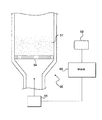
図1に示されるように、ローラ式型圧縮機10は、型圧縮される材料を受容するための漏斗12を備えている。材料は、その漏斗から、モータ16により回転する供給スクリュー14により、一対のローラ18及び20に向けて供給され、それらのローラの外部周囲面は、供給スクリュー14の下部の近くで、対向する関係にある。ローラの周囲面は、スクリュー14により供給された材料をペレットに成形するための窪みを有するように形成することができ、所望の結果に応じて、様々な他の表面構造を有することができる。ローラの周囲面は、簡単な円筒であってもよい。
As shown in FIG. 1, the
ローラ18は、モータ22により回転し、ギア又は他の適切な駆動手段(図示されず)によりローラ20に結合されるので、2つのローラは、反対方向に同じ周囲速度で回転する。
ローラ20に接続するアクチュエータ24は、ローラ回転軸の相対位置を制御して、ローラ間隔を調節するように設定される。
The
ローラ式型圧縮機では、ローラの一方又は両方は、通常、冷却液が流れる内部通路を備えている。この場合、冷却液の温度は、冷却温度制御器30を用いて所望のレベルに維持される。
In roller-type compressors, one or both of the rollers typically includes an internal passage through which coolant flows. In this case, the temperature of the coolant is maintained at a desired level using the
熱画像カメラ26は、ローラ10と20との間のローラ間隙の出口に向けられるので、型圧縮機により配送された直後の製品の温度を連続的に監視することができる。カメラ出力信号の従来のゲート開閉技術を利用して、又は、他の電子的な選択技術により、画像の一部分を選択し、画像のその部分のみから温度信号を導くことができる。製品に対応する画像の一部分を選択し、ローラ及びいずれかの他の周辺部品に対応する画像の部分を除くことにより、温度監視装置は、製品温度と、ローラ及び他の部品の温度とを区別することができ、それにより、製品温度を正確に且つ連続的に計測することができる。この選択は、制御装置28で実行される。
The thermal imaging camera 26 is directed to the exit of the roller gap between the
制御装置28は、その上、供給スクリュー駆動モータ16及びローラ回転モータ22に速度制御信号を与え、ローラ間隔アクチュエータ24及び冷却温度制御器30に追加の制御信号を与える。これらの4つの信号は、通常、個別に利用されることになる。しかしながら、それらの信号を組み合わせて利用してもよい。信号を組み合わせて利用する場合、それらの相対的な振幅は、各信号が所望の効果を有し、オーバーシュートが回避されるように設定されるべきである。
In addition, the
制御装置28がローラ駆動モータ22の速度を制御する場合、モータ速度が、監視される製品温度に正比例又は反比例して変化するように設定されるか否かは、ローラが冷却されるか否かに、及び、ローラが冷却される程度に依存する。冷却温度制御器30が有効であり、十分な冷却効果が十分に高い場合、モータ22の速度が製品温度に反比例して変化するように、制御器28を設定するのが望ましい。従って、ローラ18が十分に冷却されている場合、製品温度が上がるとローラ速度を下げることができる。そのようにすることにより、ローラ間隙での滞留時間が増し、一定の製品温度が維持されることになる。熱画像カメラから冷却器への帰還がなくローラが冷却される場合、ローラ速度と製品温度との間の同じ反比例関係を利用することができる。
When the
熱画像カメラを利用して、操作パラメータの帰還を全く制御せずに製品温度を監視することもできる。この場合、供給速度、ローラ速度、ローラ間隔、及び冷却温度等の操作パラメータの調節の効果は、各々のパラメータを個別に変えて、他のパラメータを既定の一定値に維持することにより判定することができる。この方法で操作パラメータの影響を監視することにより、所定の型圧縮機の効率のデータを記録し、プロセス最適化のためのその将来の操作に利用することができる。 A thermal imaging camera can also be used to monitor product temperature without any control of the feedback of operating parameters. In this case, the effect of adjusting operating parameters such as supply speed, roller speed, roller spacing, and cooling temperature is determined by changing each parameter individually and maintaining the other parameters at predetermined constant values. Can do. By monitoring the influence of operating parameters in this manner, the efficiency data of a given compressor can be recorded and used for future operations for process optimization.
図1に示される装置は、本発明の原理が利用され得る様々な型圧縮機の一実施例にすぎない。 The apparatus shown in FIG. 1 is only one example of various types of compressors in which the principles of the present invention may be utilized.
図1に示される特定の供給機は、粉末がローラに届く前にその粉末の或る初期の型圧縮を作り出すために尖鋭された単一の供給スクリューを利用している。供給機は、本発明の目的のために、図示されるスクリュー供給機の均等物である様々な他の形態を取ることができる。例えば、供給機は、真っ直ぐな尖鋭ではないスクリュー、若しくは、間隔距離が変化する尖鋭された又は尖鋭されていないスクリュー、好ましくは、運搬される材料がローラに近づくにつれてスクリューの巻きが漸次的に相互に近くなるものである。単一の搬送ベルト、互いに対向する2つのベルト、又は他のベルト配置が組み込まれているベルトコンベア等の他の均等な供給装置を利用することができる。粉化材料を搬送するのに適した数多くの他のコンベアのうちのいずれかを利用することもでき、それらのコンベアは、図1に示されるスクリューコンベアと同等である。 The particular feeder shown in FIG. 1 utilizes a single sharpened feed screw to create some initial mold compression of the powder before it reaches the roller. The feeder can take various other forms that are equivalent to the illustrated screw feeder for the purposes of the present invention. For example, the feeder may be a screw that is not straight or sharp, or a sharp or non-sharpened screw that varies in distance, preferably the windings of the screw progressively interact with each other as the material being conveyed approaches the roller. It will be close to. Other equivalent feeding devices such as a single conveyor belt, two belts facing each other, or a belt conveyor incorporating other belt arrangements may be utilized. Any of a number of other conveyors suitable for conveying the powdered material may be utilized, which are equivalent to the screw conveyor shown in FIG.
モータ18及び22は、好ましくは、DCサーボモータ等などの電気モータである。モータは、必要な場合、適切な減速ギア又は他の伝達装置を備えてもよい。しかしながら、油圧モータ及び、タービン等などの他の形態のモータを利用することができ、それらのモータは、その速度が制御され得る限り、上記のモータと同等と見なされる。
The
ローラ18及び20は、周囲面が対向する、いずれかの適切な型圧縮ローラであり得る。周囲面は、円筒状であってもよく、適切な窪み又は他の表面構成を有してもよい。ローラは、好ましくは円状であるが、周囲面が、適切な型圧縮ローラ間隙を形成するように協働する限り、形状が様々な非円形のローラを利用することができる。その上、ローラは、同じ方向に尖鋭され、それらの軸が平行でなくてもよく、反対方向に尖鋭されてもよい。ローラは、同じ寸法である必要はなく、幾つかの型圧縮機の形態では、2つを超えるローラを利用することができる。いずれかのそのような配置は、本発明の目的のために示されるローラと同等と見なされ得る。
ローラ間隔アクチュエータ24は、モータ・ラック及びピニオンギアが回転する電気的に操作される線形アクチュエータ等の、いずれかの適切なアクチュエータであり得る。しかしながら、油圧アクチュエータ等などの、様々な他の形態のアクチュエータのうちのいずれかを利用することができ、それらのアクチュエータは、本発明の目的において、電気的に操作される線形アクチュエータと同等である。
The
冷却温度制御器30は、好ましくは、熱交換コイルを有する冷却装置であり、その熱交換コイルにより、液体は、回転用シール又は他の適切な結合装置を通じてローラの一方又は両方に循環される。図示される装置では、冷却剤は、好ましくは、ローラ18の内部を通じて循環される。しかしながら、冷却剤は、ローラの一方又は両方の外部と接触して流れるようにされ得る。代わりに、空冷、熱電(ペルチェ効果)冷却、又は他の冷却形態を利用することができる。型圧縮ローラを冷却するのに適した制御可能な冷却装置の全ての形態は、本発明の目的のための冷却温度制御器30と同等と見なされ得る。
The
熱画像カメラ26は、実際にカメラ視野内の温度変化を電子的に表記する出力を与える様々な形態の熱画像カメラのうちのいずれかであり得る。好ましくは、カメラの出力は、その視野内の特定の選択された領域に対応する情報が、選択及び隔離され得るようなものである。 The thermal imaging camera 26 can be any of various forms of thermal imaging camera that provides an output that electronically represents the temperature change in the camera field of view. Preferably, the output of the camera is such that information corresponding to a particular selected region within its field of view can be selected and isolated.
制御器28は、マイクロプロセッサ基盤の制御器、プログラム化論理アレイ制御器、個別の論理制御器等を含んでなる、様々な形態の制御装置のうちのいずれかである。
The
上記のもの以外の様々な変更を行うことができる。例えば、熱画像カメラは、ローラ軸に平行な方向に沿って向けられてもよく、その場合、ローラ間隙を出る製品の画像と、ローラの画像及び他の部品との間の区別を容易にすることができる。加えて、適切な温度遮蔽を用いて、画像の区別を向上させることができる。 Various changes other than those described above can be made. For example, the thermal imaging camera may be oriented along a direction parallel to the roller axis, in which case it facilitates the distinction between the image of the product exiting the roller gap and the image of the roller and other parts. be able to. In addition, image discrimination can be improved using appropriate temperature shielding.
図2では、コーティングパン32が時計周りに回転する際に、そのパン内の錠剤層34が、一連のノズルを通した噴霧により膜を施される。それらノズルのうちの1つが、噴霧多分岐管38上に36で示される。ノズル38は、コーティングパンの回転によりその層が回転する時に、錠剤の表面に被膜溶液又は懸濁液を与える。噴霧パターン40の形状は、ノズルの構造により定められ、通常、一般に円錐状である。多分岐管に沿って配置される複数のノズルは、図3に示されるように重なり得る噴霧パターン40、42等を与える。
In FIG. 2, as the
コーティングパンの内部に位置し、噴霧多分岐管38の上に備え付けられ得る熱画像カメラ44は、被膜剤が噴霧されている際に、錠剤層34の表面を走査する。カメラ44の電気出力は、制御ユニット46に与えられ、次に、その制御ユニットは、1つ以上の被膜パラメータを制御する。それらのパラメータとして、コーティングパンを通るように誘導される供給空気の温度、コーティングパン自体の温度、コーティングパンの回転速度、噴霧圧力、噴霧温度、及び噴霧サイクルの継続時間が挙げられ得る。任意選択で、LCDビデオスクリーン等のスクリーン上に熱画像カメラの出力を表示することができるので、操作者は、錠剤表面の温度を監視することができる。
A
噴霧剤中の溶剤が(又は、懸濁液の場合、担体液が)蒸発冷却するので、熱画像カメラは、噴霧パターンを正確に監視することができる。従って、詰まりによるノズルの不良を検出することができるばかりでなく、被膜材料が錠剤上に堆積されている速度を定め、熱画像カメラから導かれるデータに応答して、噴霧圧及び他の処理パラメータを制御することができる。 Since the solvent in the propellant (or the carrier liquid in the case of a suspension) evaporates and cools, the thermal imaging camera can accurately monitor the spray pattern. Thus, not only can nozzle failures due to clogging be detected, but also determine the rate at which the coating material is deposited on the tablet and in response to data derived from a thermal imaging camera, spray pressure and other processing parameters Can be controlled.
以前に述べたように、噴霧パターンを監視する熱画像カメラの能力を利用して、試験設備から得られた情報に基づいて大型のコーティングパンを設計する目的のために、被膜プロセスをより良く理解することもできる。 As previously mentioned, a better understanding of the coating process for the purpose of designing large coating pans based on information obtained from the test facility, utilizing the ability of thermal imaging cameras to monitor spray patterns You can also
図4は、粒子の層52が、空気供給器56から、貫通穴付きの支持体54を通じて上方に配送される熱気により乾燥される、流体層乾燥機50を示す。乾燥機の側に配置される熱画像カメラ58の出力は、制御ユニット60に出力を与え、次に、その制御ユニットは、空気の流速及び温度等の空気供給器57の操作パラメータを制御することができる。代わりに、熱画像カメラを利用して乾燥時間を制御することができ、材料の連続バッチが処理される際に起こる乾燥機の温度分布の変化を考慮し、それに応じて乾燥時間を調節することにより、更に効率的な操作を行うことができる。処理パラメータ及び/又は乾燥時間を制御するための熱画像の利用は、連続式流体層乾燥機に、同様に、一括処理式乾燥機に適用することができる。
FIG. 4 shows a
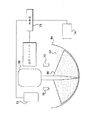
図5に示される高剪断湿式造粒装置では、円形容器64内の材料層62は、モータ66により操作される一組の刃66により混合され、他方では、1つ以上の噴霧ノズル70を通じて液体結合剤で噴霧される。第1の熱画像カメラ72は、円形容器64の上に配置されるので、材料層62の表面での温度を監視し、噴霧される結合剤のパターンを、被膜プロセス中にその結合剤の蒸発冷却を観察することにより監視することができる。第2の熱画像カメラ74を利用して造粒容器64中の温度分布を監視し、剪断力を過剰に用いることから生じる過剰な加熱を検出することができる。2つの熱画像カメラは、制御ユニット76に接続され、その制御ユニットは、結合剤噴霧速度、モータ速度及び処理時間等の、様々な造粒機の操作パラメータを次々に制御することができる。
In the high shear wet granulation apparatus shown in FIG. 5, the
図6に示される噴霧乾燥システムでは、噴霧ノズル78が、吸入口82と吐出口84とを有する格納容器80内に、乾燥されるべき材料スラリーを誘導する。熱画像カメラ86は、ノズル出口の近くで噴霧パターン88を走査し、それにより、材料スラリが噴霧ノズルを出る際のその材料スラリーの温度を計測するように設定される。熱画像カメラの出力は、制御ユニット90に接続され、その制御ユニットは、供給速度、空気供給温度、及び噴霧圧等の様々な処理パラメータを制御することができる。代わりに、熱画像カメラは、流体層乾燥機の事例のように乾燥機の外に配置されて、温度分布を監視することができる。
In the spray drying system shown in FIG. 6, a spray nozzle 78 directs material slurry to be dried into a
図7では、隔離された凍結乾燥チャンバが、凍結乾燥薬瓶96の3次元アレイを支える棚94を含んでなる。棚94の温度とチャンバ92の真空レベルは、そのチャンバ内部の熱画像カメラ100から導かれ且つそのアレイ内の薬瓶一式の温度を走査するように設定された信号に応答して、制御ユニット98により制御される。熱画像カメラは、薬瓶によって温度差を検出することができ、熱画像カメラを利用して、凍結乾燥サイクル中の幾つかの工程にわたり真空、温度及び時間等の様々なパラメータを制御し、製品に害を与えずに最適な乾燥を行うことができる。
In FIG. 7, an isolated lyophilization chamber comprises a
図8は、不活性担体の上に薬理活性材料の液滴を正確に制御された体積で誘導することにより、低用量錠剤を作製する液体分注装置の一部分を示す。装置は、行配列の担体錠剤を搬送するコンベアを含んでなり、それらの担体錠剤のうちの1つが、端に示される行配列の分注ノズル106の先に、104で端に示されている。ノズル数は、各行の担体錠剤の数に対応する。行配列の担体錠剤が行配列の分注ノズルを通過するときに、各ノズルは、活性物質の液滴を担体上に導く。次に、行配列の担体錠剤は、加熱装置108の下に搬送される。熱画像カメラ110は、行内の全ての錠剤を走査するように設定され、温度差を検出することができ、その温度差に基づいて、加熱温度、搬送モータ112の速度等の様々な処理パラメータを制御することができる。図示される実施形態では、カメラは、加熱装置から下流の短い距離に配置される。代わりに、カメラは、加熱装置の内部に配置されてもよい。
FIG. 8 shows a portion of a liquid dispensing device that produces low-dose tablets by inducing droplets of pharmacologically active material on an inert carrier in a precisely controlled volume. The apparatus comprises a conveyor for carrying a row array of carrier tablets, one of which is shown at 104 at the end of the row
図9では、参照番号114は、結晶化容器、発酵容器、沈殿容器等のような、様々な容器のうちの1つであり得る処理容器を指す。容器の温度分布は、容器の側に位置する熱画像カメラ116により監視される。熱画像カメラは、その出力を制御ユニット118に与え、その出力を利用して、温度及び処理時間等の1つ以上の処理パラメータを制御する。
In FIG. 9,
上記の各々の実施形態では、熱画像カメラを利用して、データを与えることができ、そのデータから、従来のアナログ式とデジタル式の両方の制御技術を利用して、処理パラメータを制御することができる。熱画像を利用して、人が観察し、人が制御ループに介在するための温度分布、噴霧パターン等の視覚表示を作り出すことができる。上記の装置及びプロセスに対して、様々な変更を行うことができる。複数の熱画像カメラを利用して、例えば、異なる高さに複数の棚を有する凍結乾燥チャンバの事例のように、処理を受けている材料の異なる領域を個別に観察することができる。熱画像カメラからの帰還は、処理パラメータを実時間で制御することに利用することができる。一分量の材料の処理操作から誘導される熱画像データを利用して、他の分量の同材料を後に処理操作するためのパラメータを定めることもできる。 In each of the above embodiments, the thermal imaging camera can be used to provide data, from which the processing parameters are controlled using both conventional analog and digital control techniques. Can do. Thermal images can be used to create visual displays such as temperature distributions, spray patterns, etc. for human observation and human intervention in the control loop. Various changes can be made to the above devices and processes. Multiple thermal imaging cameras can be used to individually observe different regions of the material being processed, as in the case of a lyophilization chamber having multiple shelves at different heights, for example. Feedback from the thermal imaging camera can be used to control the processing parameters in real time. The thermal image data derived from the processing of a portion of the material can also be used to define parameters for subsequent processing of another portion of the material.
他の変更は以下に示す請求項において定義される本発明の範囲から逸脱することなく上記で開示された装置および方法に作られてもよい。
以上に説明してきたように、本発明は、以下の発明を包含する。
(1)製造プロセスであって、材料を、前記材料の複数の異なる領域の温度が互いに異なるようにする処理に供する工程と、熱画像カメラを利用して前記領域を走査することにより、各々の前記領域内の複数の位置での温度を表すデータ集合を生成する工程と、前記データの変化に応答して少なくとも1つの処理パラメータを調節する、前記データに応答して前記処理を制御する工程とを含んでなる、製造プロセス。
(2)第1バッチの材料の複数の異なる領域を走査することにより得られる温度データが、異なる第2バッチの材料を後に処理するための操作パラメータを定めるのに利用される、上記(1)に記載の製造プロセス。
(3)前記材料が医薬材料である、上記(1)に記載の製造プロセス。
(4)前記処理が、リボン型圧縮、被膜、噴霧乾燥、流体層乾燥、高剪断湿式造粒、結晶化、凍結乾燥、沈殿、発酵、及び低用量の薬理活性液体の分注からなる群から選択される処理操作である、上記(1)に記載の製造プロセス。
(5)前記データ集合が、2次元画像の形態で表示される、上記(1)に記載の製造プロセス。
(6)前記データ集合が、電気信号として自動制御装置に与えられ、該制御装置が、該電気信号に応答して前記処理を制御する、上記(1)に記載の製造プロセス。
(7)医薬組成物の型圧縮機であって、粉末組成物を受容及び搬送するのに適した供給機と、周囲面が対向する一対の対回転ローラであって、前記供給機により搬送された粉末組成物を前記ローラの対向する周囲面の間で受容し、前記組成物に圧力を加え、圧縮された前記組成物で構成される製品を前記ローラに隣接する配送位置で配送するように、前記供給機に対して配置される一対の対回転ローラと、前記製品の温度を検出し、該製品の温度を表す出力信号を与えるための、前記配送位置に向けられた熱画像カメラとを含んでなる、型圧縮機。
(8)前記型圧縮機の1つ以上の操作パラメータを調節するために、前記熱画像カメラに接続され且つ前記出力信号に応答する制御器をさらに含んでなり、前記操作パラメータが、前記粉末組成物が前記供給機により搬送される速度、前記対回転ローラの回転速度、前記対回転ローラの間隔、及び前記対回転ローラの温度からなる群から選択されるパラメータである、上記(7)に記載の型圧縮機。
(9)前記制御器に応答して前記供給機を操作するように設定されたモータを含み、前記制御器が前記モータの速度を調節し、製品温度が上がると前記モータの速度を下げ、製品温度が下がると前記モータの速度を上げる、上記(8)に記載の型圧縮機。
(10)前記制御器に応答して前記供給機を操作するように設定されたモータを含み、前記制御器が、製品温度が上がると前記モータの速度を上げ、製品温度が下がると前記モータの速度を下げるように前記モータの速度を調節する、上記(8)に記載の型圧縮機。
(11)前記制御器に応答して前記ローラの相互間隔を定める間隔調節器を含み、該制御器が、製品温度が上がると前記ローラの間隔を増し、製品温度が下がると前記ローラの間隔を減らすように調節する、上記(8)に記載の型圧縮機。
(12)前記制御器に応答して前記ローラの温度を定める温度調節器を含み、該制御器が、製品温度が下がると前記ローラの温度を上げ、製品温度が上がると前記ローラの温度を下げるように調節する、上記(8)に記載の型圧縮機。
(13)前記制御器に応答して前記供給機を操作するように設定された第1モータ(該制御器は、製品温度が上がると前記第1モータの速度を下げ、製品温度が下がると前記第1モータの速度を上げるように第1モータの速度を調節する)と、前記制御器に応答して前記ローラを回転するように設定された第2モータ(該制御器は、製品温度が上がると前記第2モータの速度を上げ、製品温度が下がると前記第2モータの速度を下げるように第2モータの速度を調節する)とを含む、上記(8)に記載の型圧縮機。
(14)前記制御器に応答して前記供給機を操作するように設定されたモータ(該制御器は、製品温度が上がると前記第1モータの速度を下げ、製品温度が下がると前記モータの速度を上げるようにモータの速度を調節する)と、前記制御器に応答して前記ローラの相互間隔を定める間隔調節器(該制御器は、製品温度が上がると前記ローラの間隔を増し、製品温度が下がると前記ローラの間隔を減らすように前記ローラの間隔を調節する)とを含む、上記(8)に記載の型圧縮機。
(15)前記制御器に応答して前記供給機を操作するように設定されたモータ(該制御器は、製品温度が上がると前記第1モータの速度を下げ、製品温度が下がると前記モータの速度を上げるようにモータの速度を調節する)と、前記制御器に応答して前記ローラの温度を定める温度調節器(該制御器は、製品温度が下がると前記ローラの温度を上げ、製品温度が上がると前記ローラの温度を下げるように前記ローラの温度を調節する)とを含む、上記(8)に記載の型圧縮機。
(16)前記制御器に応答して前記ローラを回転するように設定されたモータ(該制御器は、製品温度が上がると前記モータの速度を上げ、製品温度が下がると前記モータの速度を下げるようにモータの速度を調節する)と、前記制御器に応答して前記ローラの相互間隔を定める間隔調節器(該制御器は、製品温度が上がると前記ローラの間隔を増し、製品温度が下がると前記ローラの間隔を減らすように前記ローラの間隔を調節する)とを含む、上記(8)に記載の型圧縮機。
(17)前記制御器に応答して前記ローラを回転するように設定されたモータ(該制御器は、製品温度が上がると前記モータの速度を上げ、製品温度が下がると前記モータの速度を下げるようにモータの速度を調節する)と、前記制御器に応答して前記ローラの温度を定める温度調節器(該制御器は、製品温度が下がると前記ローラの温度を上げ、製品温度が上がると前記ローラの温度を下げるように前記ローラの温度を調節する)とを含む、上記(8)に記載の型圧縮機。
(18)前記制御器に応答して前記ローラを回転するように設定されたモータ(該制御器は、製品温度が上がると前記モータの速度を下げ、製品温度が下がると前記モータの速度を上げるようにモータの速度を調節する)と、前記制御器に応答して前記ローラの温度を定める温度調節器(該制御器は、製品温度が下がると前記ローラの温度を上げ、製品温度が上がると前記ローラの温度を下げるように前記ローラの温度を調節する、)とを含む、上記(8)に記載の型圧縮機。
(19)前記制御器に応答して前記ローラの相互間隔を定める間隔調節器(該制御器は、製品温度が上がると前記ローラの間隔を増し、製品温度が下がると前記ローラの間隔を減らすように前記ローラの間隔を調節する)と、前記制御器に応答して前記ローラの温度を定める温度調節器(該制御器は、製品温度が下がると前記ローラの温度を上げ、製品温度が上がると前記ローラの温度を下げるように前記ローラの温度を調節する)とを含む、上記(8)に記載の型圧縮機。
(20)前記制御器に応答して前記供給機を操作するように設定された第1モータ(該制御器は、製品温度が上がると前記第1モータの速度を下げ、製品温度が下がると前記第1モータの速度を上げるように第1モータの速度を調節する)と、前記制御器に応答して前記ローラを回転するように設定された第2モータ(該制御器は、製品温度が上がると前記第2モータの速度を上げ、製品温度が下がると前記第2モータの速度を下げるように第2モータの速度を調節する)と、前記制御器に応答して前記ローラの相互間隔を定める間隔調節器(該制御器は、製品温度が上がると前記ローラの間隔を増し、製品温度が下がると前記ローラの間隔を減らすように前記ローラの間隔を調節する)とを含む、上記(8)に記載の型圧縮機。
(21)前記制御器に応答して前記供給機を操作するように設定された第1モータ(該制御器は、製品温度が上がると前記第1モータの速度を下げ、製品温度が下がると前記第1モータの速度を上げるように第1モータの速度を調節する)と、前記制御器に応答して前記ローラを回転するように設定された第2モータ(該制御器は、製品温度が上がると前記第2モータの速度を上げ、製品温度が下がると前記第2モータの速度を下げるように第2モータの速度を調節する)と、前記制御器に応答して前記ローラの温度を定める温度調節器(該制御器は、製品温度が下がると前記ローラの温度を上げ、製品温度が上がると前記ローラの温度を下げるように前記ローラの温度を調節する)とを含む、上記(8)に記載の型圧縮機。
(22)前記制御器に応答して前記ローラを回転するように設定されたモータ(該制御器は、製品温度が上がると前記モータの速度を上げ、製品温度が下がると前記モータの速度を下げるようにモータの速度を調節する)と、前記制御器に応答して前記ローラの相互間隔を定める間隔調節器(該制御器は、製品温度が上がると前記ローラの間隔を増し、製品温度が下がると前記ローラの間隔を減らすように前記ローラの間隔を調節する)と、前記制御器に応答して前記ローラの温度を定める温度調節器(該制御器は、製品温度が下がると前記ローラの温度を上げ、製品温度が上がると前記ローラの温度を下げるように前記ローラの温度を調節する)とを含む、上記(8)に記載の型圧縮機。
(23)前記制御器に応答して前記ローラを回転するように設定されたモータ(該制御器は、製品温度が上がると前記モータの速度を下げ、製品温度が下がると前記モータの速度を上げるようにモータの速度を調節する)と、前記制御器に応答して前記ローラの相互間隔を定める間隔調節器(該制御器は、製品温度が上がると前記ローラの間隔を増し、製品温度が下がると前記ローラの間隔を減らすように前記ローラの間隔を調節する)と、前記制御器に応答して前記ローラの温度を定める温度調節器(該制御器は、製品温度が下がると前記ローラの温度を上げ、製品温度が上がると前記ローラの温度を下げるように前記ローラの温度を調節する)とを含む、上記(8)に記載の型圧縮機。
(24)前記制御器に応答して前記供給機を操作するように設定されたモータ(該制御器は、製品温度が上がると前記第1モータの速度を下げ、製品温度が下がると前記モータの速度を上げるようにモータの速度を調節する)と、前記制御器に応答して前記ローラの相互間隔を定める間隔調節器(該制御器は、製品温度が上がると前記ローラの間隔を増し、製品温度が下がると前記ローラの間隔を減らすように前記ローラの間隔を調節する)と、前記制御器に応答して前記ローラの温度を定める温度調節器(該制御器は、製品温度が下がると前記ローラの温度を上げ、製品温度が上がると前記ローラの温度を下げるように前記ローラの温度を調節する)とを含む、上記(8)に記載の型圧縮機。
(25)前記制御器に応答して前記供給機を操作するように設定された第1モータ(該制御器は、製品温度が上がると前記第1モータの速度を下げ、製品温度が下がると前記第1モータの速度を上げるように第1モータの速度を調節する)と、前記制御器に応答して前記ローラを回転するように設定された第2モータ(該制御器は、製品温度が上がると前記第2モータの速度を上げ、製品温度が下がると前記第2モータの速度を下げるように第2モータの速度を調節する)と、前記制御器に応答して前記ローラの相互間隔を定める間隔調節器(該制御器は、製品温度が上がると前記ローラの間隔を増し、製品温度が下がると前記ローラの間隔を減らすように前記ローラの間隔を調節する)と、前記制御器に応答して前記ローラの温度を定める温度調節器(該制御器は、製品温度が下がると前記ローラの温度を上げ、製品温度が上がると前記ローラの温度を下げるように前記ローラの温度を調節する)とを含む、上記(8)に記載の型圧縮機。
(26)前記制御器に応答して前記供給機を操作するように設定された第1モータ(該制御器は、製品温度が上がると前記第1モータの速度を下げ、製品温度が下がると前記第1モータの速度を上げるように第1モータの速度を調節する)と、前記制御器に応答して前記ローラを回転するように設定された第2モータ(該制御器は、製品温度が上がると前記第2モータの速度を下げ、製品温度が下がると前記第2モータの速度を上げるように第2モータの速度を調節する)と、前記制御器に応答して前記ローラの相互間隔を定める間隔調節器(該制御器は、製品温度が上がると前記ローラの間隔を増し、製品温度が下がると前記ローラの間隔を減らすように前記ローラの間隔を調節する)と、前記制御器に応答して前記ローラの温度を定める温度調節器(該制御器は、製品温度が下がると前記ローラの温度を上げ、製品温度が上がると前記ローラの温度を下げるように前記ローラの温度を調節する)とを含む、上記(8)に記載の型圧縮機。
(27)少なくとも1つの前記ローラを冷却する手段と、前記制御器に応答して前記ローラを回転するように配置されたモータとを含み、該制御器が、製品温度が上がると前記モータの速度を下げ、製品温度が下がると前記モータの速度を上げるようにモータの速度を調節する、上記(8)に記載の型圧縮機。
(28)医薬組成物用の型圧縮機であって、粉末組成物を受容及び搬送する供給手段と、周囲面が対向する一対の対回転ローラであって、前記供給手段により搬送された粉末組成物を前記ローラの対向する周囲面の間で受容し、前記組成物に圧力を加え、圧縮された前記組成物で構成される製品を前記ローラに隣接する配送位置で配送するように、前記供給機に対して配置される一対の対回転ローラと、前記製品の温度を前記配送位置で検出し、該製品の温度を表す出力信号を与える熱画像手段と、前記型圧縮機の少なくとも1つの操作パラメータを調節するために、前記出力信号に応答する制御手段であって、前記操作パラメータが、前記粉末組成物が前記供給機により搬送される速度、前記対回転ローラの回転速度、前記対回転ローラの間隔、及び前記対回転ローラの温度からなる群から選択されるパラメータである、制御手段とを含んでなる、型圧縮機。
(29)医薬組成物を型圧縮する方法であって、周囲面が対向する一対の対回転ローラの間のローラ間隙に粉末組成物を供給し、前記ローラ間隙中の前記組成物に圧力を加える工程と、前記ローラに、圧縮された前記組成物で構成される製品を前記ローラに隣接する配送位置で配送させる工程と、前記配送位置で前記製品を熱画像化することにより、該製品の温度を表す信号を与える工程と、前記信号に応答した制御器により前記型圧縮機の少なくとも1つの操作パラメータを調節する工程であって、前記操作パラメータが、前記粉末組成物が前記ローラ間隙に供給される速度、前記対回転ローラの回転速度、前記対回転ローラの間隔、及び前記対回転ローラの温度からなる群から選択されるパラメータである、前記工程とを含んでなる、方法。
Other modifications may be made to the apparatus and methods disclosed above without departing from the scope of the invention as defined in the claims that follow.
As described above, the present invention includes the following inventions.
(1) a manufacturing process, wherein the material is subjected to a process of making the temperatures of a plurality of different regions of the material different from each other, and each region is scanned by using a thermal image camera, Generating a data set representing temperatures at a plurality of locations in the region; adjusting at least one processing parameter in response to the change in the data; and controlling the processing in response to the data; Comprising the manufacturing process.
(2) The temperature data obtained by scanning a plurality of different regions of the first batch of material is utilized to determine operating parameters for subsequent processing of the different second batch of material. The manufacturing process described in.
(3) The manufacturing process according to (1), wherein the material is a pharmaceutical material.
(4) The treatment is from the group consisting of ribbon type compression, coating, spray drying, fluid layer drying, high shear wet granulation, crystallization, freeze drying, precipitation, fermentation, and dispensing a low dose of pharmacologically active liquid. The manufacturing process according to (1) above, which is a selected processing operation.
(5) The manufacturing process according to (1), wherein the data set is displayed in the form of a two-dimensional image.
(6) The manufacturing process according to (1), wherein the data set is provided as an electrical signal to an automatic control device, and the control device controls the processing in response to the electrical signal.
(7) A mold compressor for a pharmaceutical composition, which is a feeder suitable for receiving and transporting a powder composition, and a pair of counter-rotating rollers whose peripheral surfaces are opposed to each other, which are transported by the feeder. Receiving the powder composition between opposing peripheral surfaces of the roller, applying pressure to the composition, and delivering a product composed of the compressed composition at a delivery location adjacent to the roller. A pair of counter-rotating rollers disposed with respect to the feeder and a thermal imaging camera directed to the delivery position for detecting the temperature of the product and providing an output signal representative of the temperature of the product A mold compressor comprising:
(8) further comprising a controller connected to the thermal imaging camera and responsive to the output signal to adjust one or more operating parameters of the mold compressor, the operating parameters comprising the powder composition (7) The parameter is selected from the group consisting of a speed at which an object is conveyed by the feeder, a rotational speed of the counter-rotating roller, an interval between the counter-rotating rollers, and a temperature of the counter-rotating roller. Type compressor.
(9) includes a motor set to operate the feeder in response to the controller, the controller adjusts the speed of the motor and reduces the speed of the motor when the product temperature rises; The mold compressor according to (8), wherein when the temperature decreases, the speed of the motor is increased.
(10) including a motor configured to operate the feeder in response to the controller, wherein the controller increases the speed of the motor when the product temperature rises and the motor when the product temperature decreases. The mold compressor according to (8), wherein the speed of the motor is adjusted so as to reduce the speed.
(11) It includes a distance adjuster that determines the mutual distance between the rollers in response to the controller, and the controller increases the distance between the rollers when the product temperature rises, and reduces the distance between the rollers when the product temperature falls. The type compressor according to (8), which is adjusted so as to be reduced.
(12) It includes a temperature controller that determines the temperature of the roller in response to the controller, and the controller increases the temperature of the roller when the product temperature decreases, and decreases the temperature of the roller when the product temperature increases. The type compressor according to (8) above, which is adjusted as follows.
(13) a first motor set to operate the feeder in response to the controller (the controller reduces the speed of the first motor when the product temperature rises, and Adjusting the speed of the first motor to increase the speed of the first motor) and a second motor set to rotate the roller in response to the controller (the controller increases the product temperature) And adjusting the speed of the second motor so as to decrease the speed of the second motor when the product temperature decreases).
(14) A motor set to operate the feeder in response to the controller (the controller reduces the speed of the first motor when the product temperature rises, and the motor decreases when the product temperature falls. Adjusting the speed of the motor to increase the speed), and a spacing adjuster that determines the mutual spacing of the rollers in response to the controller (the controller increases the spacing of the rollers as the product temperature increases, (8) adjusting the distance between the rollers so as to reduce the distance between the rollers when the temperature decreases).
(15) A motor set to operate the feeder in response to the controller (the controller reduces the speed of the first motor when the product temperature rises, and the motor decreases when the product temperature falls. Adjusting the speed of the motor to increase the speed), and a temperature controller that determines the temperature of the roller in response to the controller (the controller increases the temperature of the roller when the product temperature decreases, The temperature of the roller is adjusted so as to decrease the temperature of the roller as the temperature rises).
(16) A motor set to rotate the roller in response to the controller (the controller increases the speed of the motor when the product temperature increases, and decreases the motor speed when the product temperature decreases) Adjusting the speed of the motor in such a manner that the controller adjusts the distance between the rollers in response to the controller (the controller increases the distance between the rollers when the product temperature rises and the product temperature decreases). And adjusting the distance between the rollers so as to reduce the distance between the rollers).
(17) A motor set to rotate the roller in response to the controller (the controller increases the speed of the motor when the product temperature increases, and decreases the speed of the motor when the product temperature decreases) The temperature of the roller is adjusted in response to the controller, and the controller increases the temperature of the roller when the product temperature decreases, and increases the temperature of the product when the product temperature increases. And adjusting the temperature of the roller so as to lower the temperature of the roller).
(18) A motor set to rotate the roller in response to the controller (the controller decreases the speed of the motor when the product temperature increases, and increases the speed of the motor when the product temperature decreases. The temperature of the roller is adjusted in response to the controller, and the controller increases the temperature of the roller when the product temperature decreases, and increases the temperature of the product when the product temperature increases. And adjusting the temperature of the roller so as to lower the temperature of the roller).
(19) A spacing adjuster that determines the mutual spacing of the rollers in response to the controller (the controller increases the spacing between the rollers when the product temperature rises, and reduces the spacing between the rollers when the product temperature falls. And a temperature controller that determines the temperature of the roller in response to the controller (the controller increases the temperature of the roller when the product temperature decreases and increases the product temperature). And adjusting the temperature of the roller so as to lower the temperature of the roller).
(20) a first motor set to operate the feeder in response to the controller (the controller reduces the speed of the first motor when the product temperature rises, and Adjusting the speed of the first motor to increase the speed of the first motor) and a second motor set to rotate the roller in response to the controller (the controller increases the product temperature) The speed of the second motor is increased and the speed of the second motor is adjusted so as to decrease the speed of the second motor when the product temperature decreases), and the mutual spacing of the rollers is determined in response to the controller. (8) including a spacing adjuster (which adjusts the spacing of the rollers to increase the spacing of the rollers when the product temperature increases and to decrease the spacing of the rollers when the product temperature decreases). The type compressor described in 1.
(21) a first motor set to operate the feeder in response to the controller (the controller reduces the speed of the first motor when the product temperature rises, and Adjusting the speed of the first motor to increase the speed of the first motor) and a second motor set to rotate the roller in response to the controller (the controller increases the product temperature) The speed of the second motor is increased and the speed of the second motor is adjusted so as to decrease the speed of the second motor when the product temperature decreases), and the temperature that determines the temperature of the roller in response to the controller (8) The controller (the controller adjusts the temperature of the roller so as to increase the temperature of the roller when the product temperature decreases and decreases the temperature of the roller when the product temperature increases). The described type compressor.
(22) A motor set to rotate the roller in response to the controller (the controller increases the speed of the motor when the product temperature increases, and decreases the speed of the motor when the product temperature decreases) Adjusting the speed of the motor in such a manner that the controller adjusts the distance between the rollers in response to the controller (the controller increases the distance between the rollers when the product temperature rises and the product temperature decreases). And adjusting the roller spacing to reduce the roller spacing), and a temperature controller that determines the temperature of the roller in response to the controller (the controller detects the temperature of the roller as the product temperature decreases). And adjusting the temperature of the roller so as to decrease the temperature of the roller when the product temperature rises).
(23) A motor set to rotate the roller in response to the controller (the controller decreases the speed of the motor when the product temperature increases, and increases the speed of the motor when the product temperature decreases. Adjusting the speed of the motor in such a manner that the controller adjusts the distance between the rollers in response to the controller (the controller increases the distance between the rollers when the product temperature rises and the product temperature decreases). And adjusting the roller spacing to reduce the roller spacing), and a temperature controller that determines the temperature of the roller in response to the controller (the controller detects the temperature of the roller as the product temperature decreases). And adjusting the temperature of the roller so as to decrease the temperature of the roller when the product temperature rises).
(24) A motor set to operate the feeder in response to the controller (the controller reduces the speed of the first motor when the product temperature rises, and the motor decreases when the product temperature falls. Adjusting the speed of the motor to increase the speed), and a spacing adjuster that determines the mutual spacing of the rollers in response to the controller (the controller increases the spacing of the rollers as the product temperature increases, The roller spacing is adjusted to reduce the roller spacing as the temperature decreases, and a temperature regulator that determines the temperature of the rollers in response to the controller (the controller controls the temperature when the product temperature decreases). (8) adjusting the temperature of the roller so as to lower the temperature of the roller when the product temperature rises).
(25) a first motor set to operate the feeder in response to the controller (the controller reduces the speed of the first motor when the product temperature rises and Adjusting the speed of the first motor to increase the speed of the first motor) and a second motor set to rotate the roller in response to the controller (the controller increases the product temperature) The speed of the second motor is increased and the speed of the second motor is adjusted so as to decrease the speed of the second motor when the product temperature decreases), and the mutual spacing of the rollers is determined in response to the controller. A spacing adjuster (which adjusts the spacing of the rollers to increase the spacing of the rollers when the product temperature increases and decreases the spacing of the rollers when the product temperature decreases) and the controller. To determine the temperature of the roller (8) including a degree adjuster (the controller increases the temperature of the roller when the product temperature decreases and adjusts the temperature of the roller so as to decrease the temperature of the roller when the product temperature increases). The type compressor described in 1.
(26) a first motor set to operate the feeder in response to the controller (the controller reduces the speed of the first motor when the product temperature rises, and Adjusting the speed of the first motor to increase the speed of the first motor) and a second motor set to rotate the roller in response to the controller (the controller increases the product temperature) The speed of the second motor is decreased, and the speed of the second motor is adjusted to increase the speed of the second motor when the product temperature decreases), and the mutual distance between the rollers is determined in response to the controller. A spacing adjuster (which adjusts the spacing of the rollers to increase the spacing of the rollers when the product temperature increases and decreases the spacing of the rollers when the product temperature decreases) and the controller. To determine the temperature of the roller (8) including a degree adjuster (the controller increases the temperature of the roller when the product temperature decreases and adjusts the temperature of the roller so as to decrease the temperature of the roller when the product temperature increases). The type compressor described in 1.
(27) including means for cooling at least one of the rollers and a motor arranged to rotate the rollers in response to the controller, the controller speeding the motor as the product temperature increases. The mold compressor according to (8), wherein the speed of the motor is adjusted so as to increase the speed of the motor when the product temperature decreases.
(28) A mold compressor for a pharmaceutical composition, comprising a supply means for receiving and conveying a powder composition and a pair of counter-rotating rollers whose peripheral surfaces face each other, the powder composition being conveyed by the supply means Receiving the article between opposing peripheral surfaces of the roller, applying pressure to the composition and delivering a product composed of the compressed composition at a delivery location adjacent to the roller; A pair of counter-rotating rollers disposed relative to the machine, thermal image means for detecting the temperature of the product at the delivery position and providing an output signal representative of the temperature of the product, and at least one operation of the mold compressor Control means responsive to the output signal to adjust the parameters, wherein the operating parameters are the speed at which the powder composition is conveyed by the feeder, the rotational speed of the counter-rotating roller, the counter-rotating roller of Septum, and a parameter selected from the group consisting of temperature of the pair rotating roller, comprising a control unit, type compressor.
(29) A method for compressing a pharmaceutical composition, wherein a powder composition is supplied to a roller gap between a pair of counter-rotating rollers whose peripheral surfaces face each other, and pressure is applied to the composition in the roller gap. And a step of causing the roller to deliver a product composed of the compressed composition at a delivery location adjacent to the roller, and thermally imaging the product at the delivery location to produce a temperature of the product. And a step of adjusting at least one operating parameter of the mold compressor by a controller in response to the signal, wherein the operating parameter is supplied to the roller gap with the powder composition. And a step selected from the group consisting of a rotational speed of the counter-rotating roller, an interval between the counter-rotating rollers, and a temperature of the counter-rotating roller. .
Claims (8)
少なくとも1つの噴霧ノズルによって、液体中の被膜材料を、回転するコーティングパン中の錠剤に噴霧する工程を含んでなり、
ここで、前記液体は、前記被膜材料を溶解する溶媒または前記被膜材料を懸濁する担体であり、該液体は前記錠剤に接触した際に蒸発し、これにより前記被膜材料が前記錠剤上に堆積し、回転するコーティングパン中の前記錠剤の複数の領域の温度が、前記液体の蒸発に伴う蒸発冷却によって相互に異なり、
さらに、熱画像カメラを利用して前記領域を走査することにより、前記複数の領域内の温度を表すデータ集合を生成する工程、および
前記データに応答して少なくとも1つの処理パラメータを調節する工程
を含んでなり、
ここで、少なくとも1つの前記処理パラメータが、少なくとも1つの前記噴霧ノズルの上流における前記液体にかかる圧力、前記コーティングパンの回転速度、前記コーティングパンの温度、少なくとも1つの前記噴霧ノズルによって噴霧される被膜材料の温度、コーティングパンを通るように誘導される供給空気の温度、およびプロセスの継続時間からなる群から選択されるものである、プロセス。 A process for coating tablets,
Spraying the coating material in the liquid onto the tablets in the rotating coating pan by at least one spray nozzle;
Here, the liquid is a solvent that dissolves the coating material or a carrier that suspends the coating material, and the liquid evaporates when contacting the tablet, whereby the coating material is deposited on the tablet. And the temperatures of the plurality of regions of the tablet in the rotating coating pan differ from each other due to evaporative cooling accompanying the evaporation of the liquid,
And further, generating a data set representing temperatures in the plurality of regions by scanning the region using a thermal imaging camera, and adjusting at least one processing parameter in response to the data. Comprising
Wherein at least one of the processing parameters is the pressure applied to the liquid upstream of the at least one spray nozzle, the rotational speed of the coating pan, the temperature of the coating pan, the coating sprayed by the at least one spray nozzle. A process that is selected from the group consisting of the temperature of the material, the temperature of the feed air induced through the coating pan, and the duration of the process.
Applications Claiming Priority (5)
| Application Number | Priority Date | Filing Date | Title |
|---|---|---|---|
| US17854009P | 2009-05-15 | 2009-05-15 | |
| US61/178,540 | 2009-05-15 | ||
| US23359309P | 2009-08-13 | 2009-08-13 | |
| US61/233,593 | 2009-08-13 | ||
| PCT/US2010/034658 WO2010132634A1 (en) | 2009-05-15 | 2010-05-13 | Using thermal imaging for control of a manufacturing process |
Publications (2)
| Publication Number | Publication Date |
|---|---|
| JP2012526633A JP2012526633A (en) | 2012-11-01 |
| JP5661748B2 true JP5661748B2 (en) | 2015-01-28 |
Family
ID=43085322
Family Applications (1)
| Application Number | Title | Priority Date | Filing Date |
|---|---|---|---|
| JP2012510997A Expired - Fee Related JP5661748B2 (en) | 2009-05-15 | 2010-05-13 | Using thermal images to control the manufacturing process |
Country Status (8)
| Country | Link |
|---|---|
| US (3) | US9063000B2 (en) |
| EP (1) | EP2429402A4 (en) |
| JP (1) | JP5661748B2 (en) |
| CN (1) | CN102458253B (en) |
| AU (1) | AU2010248978C1 (en) |
| CA (1) | CA2761884C (en) |
| MX (2) | MX2011012133A (en) |
| WO (1) | WO2010132634A1 (en) |
Families Citing this family (16)
| Publication number | Priority date | Publication date | Assignee | Title |
|---|---|---|---|---|
| DE102008030269A1 (en) * | 2008-06-19 | 2009-12-24 | Arzneimittel Gmbh Apotheker Vetter & Co. Ravensburg | Device for serial freeze-drying |
| KR101489918B1 (en) † | 2009-11-24 | 2015-02-05 | 게아 프로세스 엔지니어링 아/에스 | A method of monitoring a spray dryer and a spray dryer comprising one or more infrared cameras |
| US9527237B2 (en) * | 2013-01-04 | 2016-12-27 | Orbital Atk, Inc. | Induction heating compaction system |
| GB2513581A (en) * | 2013-04-30 | 2014-11-05 | Res Ct Pharmaceutical Engineering Gmbh | A device and a method for monitoring a property of a coating of a solid dosage form during a coating process forming the coating of the solid dosage form |
| CN103292578B (en) * | 2013-05-08 | 2014-12-10 | 江苏大学 | Automatic control method of microwave dryer |
| EP3105060B1 (en) | 2014-02-13 | 2020-04-08 | Brown Manufacturing Group, Inc. | Ink curing apparatus and method |
| EP2995438A1 (en) * | 2014-09-10 | 2016-03-16 | Airbus Operations GmbH | A method of monitoring the process of coating a workpiece surface |
| DK178701B1 (en) * | 2015-04-01 | 2016-11-21 | Spx Flow Tech Danmark As | A method and a system for monitoring spray nozzles in a spray drying or spray cooling chamber |
| DE102015211853B3 (en) | 2015-06-25 | 2016-06-16 | Thyssenkrupp Ag | Method for coating a surface of a metal strip and metal strip coating device |
| CN105433416A (en) * | 2015-12-05 | 2016-03-30 | 安徽紫山农业科技有限公司 | Starch granulation device |
| US10365229B2 (en) * | 2015-12-31 | 2019-07-30 | Kaiser Optical Systems, Inc. | Real-time characterization of pharmaceutical tablet coatings using Raman spectroscopy |
| DE102016000135B3 (en) * | 2016-01-11 | 2017-01-26 | Heye International Gmbh | Apparatus for producing hollow glass articles |
| DE102017109948A1 (en) | 2017-05-09 | 2018-11-15 | Glatt Maschinen- Und Apparatebau Ag | Apparatus and method for granulating a powder or a powder mixture |
| CN110339782A (en) * | 2019-06-10 | 2019-10-18 | 李志鹏 | A kind of prilling granulator of compound fertilizer production |
| CN110935397A (en) * | 2019-12-04 | 2020-03-31 | 四川吉瑞德新能源材料有限公司 | Secondary graphite granulating device and secondary granulating method |
| US11283972B1 (en) * | 2020-04-02 | 2022-03-22 | Forrest Lee Dahmes | Camera enclosure for harsh commercial environments and method for using same |
Family Cites Families (38)
| Publication number | Priority date | Publication date | Assignee | Title |
|---|---|---|---|---|
| NL6908935A (en) * | 1969-06-12 | 1970-12-15 | ||
| GB1466286A (en) * | 1974-07-16 | 1977-03-02 | Evans Medical Ltd | Coating of tablets |
| US4111626A (en) * | 1975-02-27 | 1978-09-05 | Takeda Chemical Industries, Ltd. | Powder compacting machine |
| JPS57105233A (en) * | 1980-12-23 | 1982-06-30 | Hitachi Ltd | Granulating apparatus |
| DE3132210A1 (en) * | 1981-08-14 | 1983-03-03 | Draiswerke Gmbh, 6800 Mannheim | "ROLLING MILL FOR THE CRUSHING OF LIQUIDS" |
| US4554887A (en) * | 1984-05-22 | 1985-11-26 | Vector Corporation | Apparatus for coating tablets with computer control |
| US5038709A (en) * | 1988-08-22 | 1991-08-13 | Freund Industrial Co., Ltd. | Granulating and coating apparatus |
| JPH0657398B2 (en) * | 1990-09-11 | 1994-08-03 | 株式会社新潟鐵工所 | Cutting device for frozen sliced fish |
| JP2616635B2 (en) | 1992-04-15 | 1997-06-04 | 株式会社栗本鐵工所 | Dry compression granulation method and apparatus therefor |
| US5495418A (en) * | 1993-06-18 | 1996-02-27 | Latini Machine Company | Automatic panning system |
| JPH0857289A (en) * | 1994-08-22 | 1996-03-05 | Freunt Ind Co Ltd | Spray device, washing device, feed device, pan coating control device and pan coating apparatus consisting of them |
| JP3706136B2 (en) * | 1994-09-21 | 2005-10-12 | ネクター セラピューティクス | Apparatus and method for dispersing dry powder drug |
| US6013915A (en) * | 1998-02-10 | 2000-01-11 | Philip Morris Incorporated | Process control by transient thermography |
| US6122836A (en) * | 1998-05-07 | 2000-09-26 | S.P. Industries, Inc., The Virtis Division | Freeze drying apparatus and method employing vapor flow monitoring and/or vacuum pressure control |
| NL1010930C1 (en) * | 1998-12-31 | 2000-07-03 | Stork Pmt | Method and device for processing slaughter products. |
| US6690464B1 (en) * | 1999-02-19 | 2004-02-10 | Spectral Dimensions, Inc. | High-volume on-line spectroscopic composition testing of manufactured pharmaceutical dosage units |
| WO2001061293A1 (en) * | 2000-02-18 | 2001-08-23 | Spectral Dimensions, Inc. | Multi-source spectrometry |
| JP2002095950A (en) | 2000-09-25 | 2002-04-02 | Sintokogio Ltd | Operation state monitoring system of granulator |
| US6543155B2 (en) * | 2001-03-01 | 2003-04-08 | National Agricultural Research Organization | Freeze-dried product and process and apparatus for producing it |
| US6564471B1 (en) * | 2001-03-12 | 2003-05-20 | S. P. Industries, Inc., The Virtis Division | Method and apparatus for freeze-drying |
| GB2373860B (en) * | 2001-03-28 | 2004-12-15 | Reflowtech Internat Ltd | Monitoring system |
| JP2004529359A (en) * | 2001-05-21 | 2004-09-24 | プレスコ テクノロジー インコーポレーテッド | Apparatus and method for providing snapshot operated thermal infrared imaging within an automated process control article inspection application |
| US20030004470A1 (en) * | 2001-07-02 | 2003-01-02 | Barry Hickerson | Method and apparatus for managing temperature and flow of medical fluids |
| US6624396B2 (en) * | 2001-08-28 | 2003-09-23 | Hatco Corporation | Conveyor speed control system for a conveyor oven |
| UA76810C2 (en) * | 2001-12-10 | 2006-09-15 | Мерк Енд Ко., Інк. | Pharmaceutical compositions of tachikinine receptor antagonist in form of nanoparticles |
| GB0201520D0 (en) * | 2002-01-23 | 2002-03-13 | Novartis Ag | Pharmaceutical uses |
| US7169450B2 (en) * | 2002-05-15 | 2007-01-30 | Mcneil-Ppc, Inc. | Enrobed core |
| JP2004216745A (en) * | 2003-01-16 | 2004-08-05 | Riso Kagaku Corp | Stencil paper carrying method and device in addition to stencil paper roll |
| US7129492B2 (en) * | 2003-07-29 | 2006-10-31 | Toyota Motor Manufacturing North America, Inc. | Systems and methods for inspecting coatings |
| TWI356036B (en) * | 2004-06-09 | 2012-01-11 | Smithkline Beecham Corp | Apparatus and method for pharmaceutical production |
| JP3857703B2 (en) * | 2004-08-19 | 2006-12-13 | 株式会社日本製鋼所 | Manufacturing method and manufacturing apparatus of molded body |
| US7930064B2 (en) * | 2004-11-19 | 2011-04-19 | Parata Systems, Llc | Automated drug discrimination during dispensing |
| GB0605723D0 (en) * | 2006-03-23 | 2006-05-03 | 3M Innovative Properties Co | Powder filling processes |
| CN101100520A (en) * | 2006-07-04 | 2008-01-09 | 谢基生 | Method for producing infrared permeable black plastic products and application thereof |
| JP2010506129A (en) * | 2006-10-03 | 2010-02-25 | ワイス エルエルシー | Freeze drying method and equipment |
| MX2009009036A (en) * | 2007-02-21 | 2009-08-31 | Smithkline Beecham Corp | Continuous coating of pellets. |
| CN101790676B (en) * | 2007-07-27 | 2012-07-18 | 葛兰素史密斯克莱有限责任公司 | Method for measuring product temperature during processing by temperature sensor inputting wireless transmission data to external receiver |
| US8577120B1 (en) * | 2009-11-05 | 2013-11-05 | The United States Of America As Represented By The Administrator Of The National Aeronautics And Space Administration | Methods and systems for characterization of an anomaly using infrared flash thermography |
-
2010
- 2010-05-13 MX MX2011012133A patent/MX2011012133A/en active IP Right Grant
- 2010-05-13 MX MX2015006571A patent/MX340994B/en unknown
- 2010-05-13 EP EP10775515.9A patent/EP2429402A4/en not_active Withdrawn
- 2010-05-13 WO PCT/US2010/034658 patent/WO2010132634A1/en active Application Filing
- 2010-05-13 US US13/319,535 patent/US9063000B2/en not_active Expired - Fee Related
- 2010-05-13 JP JP2012510997A patent/JP5661748B2/en not_active Expired - Fee Related
- 2010-05-13 CA CA2761884A patent/CA2761884C/en not_active Expired - Fee Related
- 2010-05-13 CN CN201080031581.5A patent/CN102458253B/en not_active Expired - Fee Related
- 2010-05-13 AU AU2010248978A patent/AU2010248978C1/en not_active Ceased
-
2015
- 2015-02-18 US US14/624,862 patent/US20150159950A1/en not_active Abandoned
- 2015-02-18 US US14/624,937 patent/US20150163417A1/en not_active Abandoned
Also Published As
| Publication number | Publication date |
|---|---|
| AU2010248978B2 (en) | 2013-10-10 |
| MX340994B (en) | 2016-08-02 |
| CA2761884C (en) | 2017-08-08 |
| US20150159950A1 (en) | 2015-06-11 |
| WO2010132634A1 (en) | 2010-11-18 |
| CN102458253A (en) | 2012-05-16 |
| AU2010248978C1 (en) | 2014-04-17 |
| EP2429402A4 (en) | 2017-03-15 |
| JP2012526633A (en) | 2012-11-01 |
| MX2011012133A (en) | 2011-12-06 |
| AU2010248978A1 (en) | 2011-12-01 |
| EP2429402A1 (en) | 2012-03-21 |
| US20150163417A1 (en) | 2015-06-11 |
| US9063000B2 (en) | 2015-06-23 |
| CA2761884A1 (en) | 2010-11-18 |
| CN102458253B (en) | 2014-12-10 |
| US20120057018A1 (en) | 2012-03-08 |
Similar Documents
| Publication | Publication Date | Title |
|---|---|---|
| JP5661748B2 (en) | Using thermal images to control the manufacturing process | |
| US10111811B2 (en) | Air-cooling micro drop pill capsule production line | |
| JP2022177311A (en) | Three-dimensional printing device and method | |
| CN101687216B (en) | Continuous coating of pellets | |
| US8978576B2 (en) | Spiral gas-solids contact apparatus | |
| US4578021A (en) | Apparatus for the production of granules from two-phase mixtures | |
| AU2006314651A1 (en) | Process and apparatus for filling a container with food articles | |
| CN204170103U (en) | Air cooling dripping pill production line | |
| Vervaet et al. | Continuous processing of pharmaceuticals | |
| EP2548637B1 (en) | Coating device and coating method | |
| JP2024504375A (en) | Drying chamber for bulk freeze drying systems | |
| CN215864332U (en) | Freeze-drying system | |
| US11940214B1 (en) | Freeze-dried product | |
| CN110090595A (en) | A kind of inclined-plane cooling granulation system | |
| EP3772285B1 (en) | Pulverization of a substance | |
| JP2000000456A (en) | Granulating method and device and granulated matter obtained by same | |
| CN113701457A (en) | Freeze-drying system and freeze-drying method | |
| CN117546882A (en) | Preparation production equipment for wheat germ biscuits | |
| JP2000185246A (en) | Spray gun having temperature retaining function and coating device using the same |
Legal Events
| Date | Code | Title | Description |
|---|---|---|---|
| A621 | Written request for application examination |
Free format text: JAPANESE INTERMEDIATE CODE: A621 Effective date: 20130329 |
|
| A977 | Report on retrieval |
Free format text: JAPANESE INTERMEDIATE CODE: A971007 Effective date: 20140124 |
|
| A131 | Notification of reasons for refusal |
Free format text: JAPANESE INTERMEDIATE CODE: A131 Effective date: 20140128 |
|
| A601 | Written request for extension of time |
Free format text: JAPANESE INTERMEDIATE CODE: A601 Effective date: 20140428 |
|
| A602 | Written permission of extension of time |
Free format text: JAPANESE INTERMEDIATE CODE: A602 Effective date: 20140508 |
|
| A601 | Written request for extension of time |
Free format text: JAPANESE INTERMEDIATE CODE: A601 Effective date: 20140528 |
|
| A602 | Written permission of extension of time |
Free format text: JAPANESE INTERMEDIATE CODE: A602 Effective date: 20140604 |
|
| A521 | Request for written amendment filed |
Free format text: JAPANESE INTERMEDIATE CODE: A523 Effective date: 20140630 |
|
| TRDD | Decision of grant or rejection written | ||
| A01 | Written decision to grant a patent or to grant a registration (utility model) |
Free format text: JAPANESE INTERMEDIATE CODE: A01 Effective date: 20141104 |
|
| A61 | First payment of annual fees (during grant procedure) |
Free format text: JAPANESE INTERMEDIATE CODE: A61 Effective date: 20141203 |
|
| R150 | Certificate of patent or registration of utility model |
Ref document number: 5661748 Country of ref document: JP Free format text: JAPANESE INTERMEDIATE CODE: R150 |
|
| R250 | Receipt of annual fees |
Free format text: JAPANESE INTERMEDIATE CODE: R250 |
|
| LAPS | Cancellation because of no payment of annual fees |