EP2814654B2 - Injection molding compounder and method - Google Patents
Injection molding compounder and method Download PDFInfo
- Publication number
- EP2814654B2 EP2814654B2 EP13706216.2A EP13706216A EP2814654B2 EP 2814654 B2 EP2814654 B2 EP 2814654B2 EP 13706216 A EP13706216 A EP 13706216A EP 2814654 B2 EP2814654 B2 EP 2814654B2
- Authority
- EP
- European Patent Office
- Prior art keywords
- injection
- extruder
- screw
- melt
- compounder
- Prior art date
- Legal status (The legal status is an assumption and is not a legal conclusion. Google has not performed a legal analysis and makes no representation as to the accuracy of the status listed.)
- Active
Links
- 238000001746 injection moulding Methods 0.000 title claims description 65
- 238000000034 method Methods 0.000 title claims description 25
- 238000002347 injection Methods 0.000 claims description 242
- 239000007924 injection Substances 0.000 claims description 242
- 239000000155 melt Substances 0.000 claims description 89
- 239000000463 material Substances 0.000 claims description 62
- 238000002156 mixing Methods 0.000 claims description 32
- 239000004033 plastic Substances 0.000 claims description 30
- 229920003023 plastic Polymers 0.000 claims description 30
- 230000008569 process Effects 0.000 claims description 23
- 238000004804 winding Methods 0.000 claims description 8
- 238000004519 manufacturing process Methods 0.000 claims description 7
- 238000003860 storage Methods 0.000 claims description 7
- 238000002844 melting Methods 0.000 claims description 3
- 230000008018 melting Effects 0.000 claims description 3
- 230000004323 axial length Effects 0.000 claims description 2
- 230000005484 gravity Effects 0.000 claims description 2
- 230000001419 dependent effect Effects 0.000 claims 1
- 230000002123 temporal effect Effects 0.000 claims 1
- 239000000835 fiber Substances 0.000 description 12
- 239000000203 mixture Substances 0.000 description 9
- 239000008187 granular material Substances 0.000 description 7
- 230000008901 benefit Effects 0.000 description 5
- 238000006073 displacement reaction Methods 0.000 description 5
- 238000000265 homogenisation Methods 0.000 description 5
- 150000001875 compounds Chemical class 0.000 description 4
- 238000012545 processing Methods 0.000 description 4
- 238000007906 compression Methods 0.000 description 3
- 230000006835 compression Effects 0.000 description 3
- 238000004590 computer program Methods 0.000 description 3
- 238000007872 degassing Methods 0.000 description 3
- 230000010006 flight Effects 0.000 description 3
- 239000003365 glass fiber Substances 0.000 description 3
- 239000004971 Cross linker Substances 0.000 description 2
- 239000004698 Polyethylene Substances 0.000 description 2
- -1 Polypropylene Polymers 0.000 description 2
- 239000004743 Polypropylene Substances 0.000 description 2
- 239000000654 additive Substances 0.000 description 2
- 230000008859 change Effects 0.000 description 2
- 238000001816 cooling Methods 0.000 description 2
- 238000013461 design Methods 0.000 description 2
- 238000010586 diagram Methods 0.000 description 2
- 239000012765 fibrous filler Substances 0.000 description 2
- 238000005469 granulation Methods 0.000 description 2
- 230000003179 granulation Effects 0.000 description 2
- 230000033001 locomotion Effects 0.000 description 2
- 239000012778 molding material Substances 0.000 description 2
- 150000002978 peroxides Chemical class 0.000 description 2
- 229920000642 polymer Polymers 0.000 description 2
- 229920001155 polypropylene Polymers 0.000 description 2
- 230000007704 transition Effects 0.000 description 2
- 229920000049 Carbon (fiber) Polymers 0.000 description 1
- 239000004952 Polyamide Substances 0.000 description 1
- 239000004676 acrylonitrile butadiene styrene Substances 0.000 description 1
- 230000000996 additive effect Effects 0.000 description 1
- 239000004917 carbon fiber Substances 0.000 description 1
- 239000000919 ceramic Substances 0.000 description 1
- 238000004140 cleaning Methods 0.000 description 1
- 238000013329 compounding Methods 0.000 description 1
- 238000011109 contamination Methods 0.000 description 1
- 230000008878 coupling Effects 0.000 description 1
- 238000010168 coupling process Methods 0.000 description 1
- 238000005859 coupling reaction Methods 0.000 description 1
- 238000005336 cracking Methods 0.000 description 1
- 239000000945 filler Substances 0.000 description 1
- 238000010438 heat treatment Methods 0.000 description 1
- 230000006872 improvement Effects 0.000 description 1
- 239000011256 inorganic filler Substances 0.000 description 1
- 230000007774 longterm Effects 0.000 description 1
- 238000012423 maintenance Methods 0.000 description 1
- 230000006386 memory function Effects 0.000 description 1
- 239000002991 molded plastic Substances 0.000 description 1
- 238000012544 monitoring process Methods 0.000 description 1
- 239000000178 monomer Substances 0.000 description 1
- 239000002245 particle Substances 0.000 description 1
- 229920002647 polyamide Polymers 0.000 description 1
- 239000004417 polycarbonate Substances 0.000 description 1
- 229920000515 polycarbonate Polymers 0.000 description 1
- 229920000573 polyethylene Polymers 0.000 description 1
- 239000004626 polylactic acid Substances 0.000 description 1
- 238000002360 preparation method Methods 0.000 description 1
- 239000012783 reinforcing fiber Substances 0.000 description 1
- 239000007787 solid Substances 0.000 description 1
- 239000007858 starting material Substances 0.000 description 1
- 239000000454 talc Substances 0.000 description 1
- 229910052623 talc Inorganic materials 0.000 description 1
- 229920001169 thermoplastic Polymers 0.000 description 1
- 239000004634 thermosetting polymer Substances 0.000 description 1
- 229920001187 thermosetting polymer Polymers 0.000 description 1
- 239000011345 viscous material Substances 0.000 description 1
Images

Classifications
-
- B—PERFORMING OPERATIONS; TRANSPORTING
- B29—WORKING OF PLASTICS; WORKING OF SUBSTANCES IN A PLASTIC STATE IN GENERAL
- B29C—SHAPING OR JOINING OF PLASTICS; SHAPING OF MATERIAL IN A PLASTIC STATE, NOT OTHERWISE PROVIDED FOR; AFTER-TREATMENT OF THE SHAPED PRODUCTS, e.g. REPAIRING
- B29C45/00—Injection moulding, i.e. forcing the required volume of moulding material through a nozzle into a closed mould; Apparatus therefor
- B29C45/17—Component parts, details or accessories; Auxiliary operations
- B29C45/46—Means for plasticising or homogenising the moulding material or forcing it into the mould
- B29C45/47—Means for plasticising or homogenising the moulding material or forcing it into the mould using screws
- B29C45/48—Plasticising screw and injection screw comprising two separate screws
-
- B—PERFORMING OPERATIONS; TRANSPORTING
- B29—WORKING OF PLASTICS; WORKING OF SUBSTANCES IN A PLASTIC STATE IN GENERAL
- B29C—SHAPING OR JOINING OF PLASTICS; SHAPING OF MATERIAL IN A PLASTIC STATE, NOT OTHERWISE PROVIDED FOR; AFTER-TREATMENT OF THE SHAPED PRODUCTS, e.g. REPAIRING
- B29C45/00—Injection moulding, i.e. forcing the required volume of moulding material through a nozzle into a closed mould; Apparatus therefor
- B29C45/17—Component parts, details or accessories; Auxiliary operations
- B29C45/76—Measuring, controlling or regulating
- B29C45/762—Measuring, controlling or regulating the sequence of operations of an injection cycle
-
- B—PERFORMING OPERATIONS; TRANSPORTING
- B29—WORKING OF PLASTICS; WORKING OF SUBSTANCES IN A PLASTIC STATE IN GENERAL
- B29C—SHAPING OR JOINING OF PLASTICS; SHAPING OF MATERIAL IN A PLASTIC STATE, NOT OTHERWISE PROVIDED FOR; AFTER-TREATMENT OF THE SHAPED PRODUCTS, e.g. REPAIRING
- B29C48/00—Extrusion moulding, i.e. expressing the moulding material through a die or nozzle which imparts the desired form; Apparatus therefor
- B29C48/25—Component parts, details or accessories; Auxiliary operations
- B29C48/36—Means for plasticising or homogenising the moulding material or forcing it through the nozzle or die
- B29C48/375—Plasticisers, homogenisers or feeders comprising two or more stages
- B29C48/385—Plasticisers, homogenisers or feeders comprising two or more stages using two or more serially arranged screws in separate barrels
-
- B—PERFORMING OPERATIONS; TRANSPORTING
- B29—WORKING OF PLASTICS; WORKING OF SUBSTANCES IN A PLASTIC STATE IN GENERAL
- B29C—SHAPING OR JOINING OF PLASTICS; SHAPING OF MATERIAL IN A PLASTIC STATE, NOT OTHERWISE PROVIDED FOR; AFTER-TREATMENT OF THE SHAPED PRODUCTS, e.g. REPAIRING
- B29C48/00—Extrusion moulding, i.e. expressing the moulding material through a die or nozzle which imparts the desired form; Apparatus therefor
- B29C48/25—Component parts, details or accessories; Auxiliary operations
- B29C48/92—Measuring, controlling or regulating
-
- B—PERFORMING OPERATIONS; TRANSPORTING
- B29—WORKING OF PLASTICS; WORKING OF SUBSTANCES IN A PLASTIC STATE IN GENERAL
- B29B—PREPARATION OR PRETREATMENT OF THE MATERIAL TO BE SHAPED; MAKING GRANULES OR PREFORMS; RECOVERY OF PLASTICS OR OTHER CONSTITUENTS OF WASTE MATERIAL CONTAINING PLASTICS
- B29B7/00—Mixing; Kneading
- B29B7/30—Mixing; Kneading continuous, with mechanical mixing or kneading devices
- B29B7/34—Mixing; Kneading continuous, with mechanical mixing or kneading devices with movable mixing or kneading devices
- B29B7/38—Mixing; Kneading continuous, with mechanical mixing or kneading devices with movable mixing or kneading devices rotary
- B29B7/40—Mixing; Kneading continuous, with mechanical mixing or kneading devices with movable mixing or kneading devices rotary with single shaft
- B29B7/42—Mixing; Kneading continuous, with mechanical mixing or kneading devices with movable mixing or kneading devices rotary with single shaft with screw or helix
- B29B7/426—Mixing; Kneading continuous, with mechanical mixing or kneading devices with movable mixing or kneading devices rotary with single shaft with screw or helix with consecutive casings or screws, e.g. for charging, discharging, mixing
-
- B—PERFORMING OPERATIONS; TRANSPORTING
- B29—WORKING OF PLASTICS; WORKING OF SUBSTANCES IN A PLASTIC STATE IN GENERAL
- B29C—SHAPING OR JOINING OF PLASTICS; SHAPING OF MATERIAL IN A PLASTIC STATE, NOT OTHERWISE PROVIDED FOR; AFTER-TREATMENT OF THE SHAPED PRODUCTS, e.g. REPAIRING
- B29C2945/00—Indexing scheme relating to injection moulding, i.e. forcing the required volume of moulding material through a nozzle into a closed mould
- B29C2945/76—Measuring, controlling or regulating
- B29C2945/76003—Measured parameter
- B29C2945/76066—Time
- B29C2945/76076—Time duration
-
- B—PERFORMING OPERATIONS; TRANSPORTING
- B29—WORKING OF PLASTICS; WORKING OF SUBSTANCES IN A PLASTIC STATE IN GENERAL
- B29C—SHAPING OR JOINING OF PLASTICS; SHAPING OF MATERIAL IN A PLASTIC STATE, NOT OTHERWISE PROVIDED FOR; AFTER-TREATMENT OF THE SHAPED PRODUCTS, e.g. REPAIRING
- B29C2945/00—Indexing scheme relating to injection moulding, i.e. forcing the required volume of moulding material through a nozzle into a closed mould
- B29C2945/76—Measuring, controlling or regulating
- B29C2945/76177—Location of measurement
- B29C2945/7618—Injection unit
- B29C2945/76214—Injection unit drive means
-
- B—PERFORMING OPERATIONS; TRANSPORTING
- B29—WORKING OF PLASTICS; WORKING OF SUBSTANCES IN A PLASTIC STATE IN GENERAL
- B29C—SHAPING OR JOINING OF PLASTICS; SHAPING OF MATERIAL IN A PLASTIC STATE, NOT OTHERWISE PROVIDED FOR; AFTER-TREATMENT OF THE SHAPED PRODUCTS, e.g. REPAIRING
- B29C2945/00—Indexing scheme relating to injection moulding, i.e. forcing the required volume of moulding material through a nozzle into a closed mould
- B29C2945/76—Measuring, controlling or regulating
- B29C2945/76344—Phase or stage of measurement
- B29C2945/76351—Feeding
-
- B—PERFORMING OPERATIONS; TRANSPORTING
- B29—WORKING OF PLASTICS; WORKING OF SUBSTANCES IN A PLASTIC STATE IN GENERAL
- B29C—SHAPING OR JOINING OF PLASTICS; SHAPING OF MATERIAL IN A PLASTIC STATE, NOT OTHERWISE PROVIDED FOR; AFTER-TREATMENT OF THE SHAPED PRODUCTS, e.g. REPAIRING
- B29C2945/00—Indexing scheme relating to injection moulding, i.e. forcing the required volume of moulding material through a nozzle into a closed mould
- B29C2945/76—Measuring, controlling or regulating
- B29C2945/76344—Phase or stage of measurement
- B29C2945/76367—Metering
-
- B—PERFORMING OPERATIONS; TRANSPORTING
- B29—WORKING OF PLASTICS; WORKING OF SUBSTANCES IN A PLASTIC STATE IN GENERAL
- B29C—SHAPING OR JOINING OF PLASTICS; SHAPING OF MATERIAL IN A PLASTIC STATE, NOT OTHERWISE PROVIDED FOR; AFTER-TREATMENT OF THE SHAPED PRODUCTS, e.g. REPAIRING
- B29C2945/00—Indexing scheme relating to injection moulding, i.e. forcing the required volume of moulding material through a nozzle into a closed mould
- B29C2945/76—Measuring, controlling or regulating
- B29C2945/76344—Phase or stage of measurement
- B29C2945/76381—Injection
-
- B—PERFORMING OPERATIONS; TRANSPORTING
- B29—WORKING OF PLASTICS; WORKING OF SUBSTANCES IN A PLASTIC STATE IN GENERAL
- B29C—SHAPING OR JOINING OF PLASTICS; SHAPING OF MATERIAL IN A PLASTIC STATE, NOT OTHERWISE PROVIDED FOR; AFTER-TREATMENT OF THE SHAPED PRODUCTS, e.g. REPAIRING
- B29C2945/00—Indexing scheme relating to injection moulding, i.e. forcing the required volume of moulding material through a nozzle into a closed mould
- B29C2945/76—Measuring, controlling or regulating
- B29C2945/76929—Controlling method
- B29C2945/76939—Using stored or historical data sets
-
- B—PERFORMING OPERATIONS; TRANSPORTING
- B29—WORKING OF PLASTICS; WORKING OF SUBSTANCES IN A PLASTIC STATE IN GENERAL
- B29C—SHAPING OR JOINING OF PLASTICS; SHAPING OF MATERIAL IN A PLASTIC STATE, NOT OTHERWISE PROVIDED FOR; AFTER-TREATMENT OF THE SHAPED PRODUCTS, e.g. REPAIRING
- B29C2948/00—Indexing scheme relating to extrusion moulding
- B29C2948/92—Measuring, controlling or regulating
- B29C2948/92009—Measured parameter
- B29C2948/92085—Velocity
- B29C2948/92104—Flow or feed rate
-
- B—PERFORMING OPERATIONS; TRANSPORTING
- B29—WORKING OF PLASTICS; WORKING OF SUBSTANCES IN A PLASTIC STATE IN GENERAL
- B29C—SHAPING OR JOINING OF PLASTICS; SHAPING OF MATERIAL IN A PLASTIC STATE, NOT OTHERWISE PROVIDED FOR; AFTER-TREATMENT OF THE SHAPED PRODUCTS, e.g. REPAIRING
- B29C2948/00—Indexing scheme relating to extrusion moulding
- B29C2948/92—Measuring, controlling or regulating
- B29C2948/92323—Location or phase of measurement
- B29C2948/92361—Extrusion unit
- B29C2948/9238—Feeding, melting, plasticising or pumping zones, e.g. the melt itself
- B29C2948/924—Barrel or housing
-
- B—PERFORMING OPERATIONS; TRANSPORTING
- B29—WORKING OF PLASTICS; WORKING OF SUBSTANCES IN A PLASTIC STATE IN GENERAL
- B29C—SHAPING OR JOINING OF PLASTICS; SHAPING OF MATERIAL IN A PLASTIC STATE, NOT OTHERWISE PROVIDED FOR; AFTER-TREATMENT OF THE SHAPED PRODUCTS, e.g. REPAIRING
- B29C2948/00—Indexing scheme relating to extrusion moulding
- B29C2948/92—Measuring, controlling or regulating
- B29C2948/92504—Controlled parameter
- B29C2948/92514—Pressure
-
- B—PERFORMING OPERATIONS; TRANSPORTING
- B29—WORKING OF PLASTICS; WORKING OF SUBSTANCES IN A PLASTIC STATE IN GENERAL
- B29C—SHAPING OR JOINING OF PLASTICS; SHAPING OF MATERIAL IN A PLASTIC STATE, NOT OTHERWISE PROVIDED FOR; AFTER-TREATMENT OF THE SHAPED PRODUCTS, e.g. REPAIRING
- B29C2948/00—Indexing scheme relating to extrusion moulding
- B29C2948/92—Measuring, controlling or regulating
- B29C2948/92504—Controlled parameter
- B29C2948/9258—Velocity
- B29C2948/926—Flow or feed rate
-
- B—PERFORMING OPERATIONS; TRANSPORTING
- B29—WORKING OF PLASTICS; WORKING OF SUBSTANCES IN A PLASTIC STATE IN GENERAL
- B29C—SHAPING OR JOINING OF PLASTICS; SHAPING OF MATERIAL IN A PLASTIC STATE, NOT OTHERWISE PROVIDED FOR; AFTER-TREATMENT OF THE SHAPED PRODUCTS, e.g. REPAIRING
- B29C2948/00—Indexing scheme relating to extrusion moulding
- B29C2948/92—Measuring, controlling or regulating
- B29C2948/92819—Location or phase of control
- B29C2948/92857—Extrusion unit
- B29C2948/92876—Feeding, melting, plasticising or pumping zones, e.g. the melt itself
- B29C2948/92895—Barrel or housing
Definitions
- the invention relates to an injection molding compounder according to the preamble of claim 1, a corresponding method for producing an injection molded workpiece and a computer program product for controlling a corresponding injection molding compounder.
- the EN 10 2007 042 808 B3 relates to an injection unit of a plastic injection molding machine, with a continuously operable plasticizing device, and with an injection device, wherein the injection device has an injection cylinder in which a displacement element for injecting melt from the injection cylinder (20,106) into an injection molding tool is arranged and can be moved axially by a drive unit, wherein the displacement element is connected to the drive unit via one or more connecting elements, wherein a first melt channel opening into the injection cylinder is provided at the front end of the injection cylinder, wherein a second melt channel opening into the injection cylinder is provided in a rear region of the injection cylinder, wherein the first and the second melt channel are alternately connectable to the outlet of the plasticizing device, wherein one or more of the connecting elements forms or form a buffer volume with the inner wall of the injection cylinder for receiving melt, and wherein the displacement element has one or more closable openings for the flow of melt.
- a screw equipped with a non-return valve is provided in the injection cylinder, the head of the screw including the non-return valve being provided as the displacement element, the screw having one or more screw flights, the screw forming part of the connecting element or elements, and that the drive unit has a linear and a rotary drive for the screw.
- Thermoplastic polymers or thermosetting polymers and mixtures thereof are used as materials, and organic or inorganic or fibrous fillers or ceramics are used.
- mixing should not be carried out for too long or too extensively, as this can reduce the chain length of the polymers and fibrous fillers can break, thereby reducing the strength of the injection-molded workpiece produced.
- the object of the present invention is to provide an injection molding compounder in which sufficiently good mixing and as little damage to the plastic components as possible through mixing occurs with as little effort as possible. Furthermore, the apparatus design of the injection molding compounder should be as simple as possible so that, if necessary, existing equipment at a plastics processor can be used for the injection molding compounder and the investment costs can be low.
- An injection molding compounder has an extruder with at least one extruder screw arranged in an extruder housing, an injection unit with an injection screw arranged in an injection housing, the injection unit having an effective length defined from the injection nozzle of the injection unit to the end of the turns of the injection screw remote therefrom. This effective length is preferably defined in the advanced position of the injection unit, i.e. immediately after the injection process.
- a melt inlet is provided on the injection housing, which is connected to an outlet of the extruder, the melt inlet being more than a third of the effective length away from the injection nozzle.
- the direction of the effective length is preferably measured in the axial direction of the injection unit.
- the effective length is preferably considered or defined when the injection screw or the pusher screw is in its position remote from the injection nozzle. Due to the described structure, the melt produced by the extruder is guided along at least part of the injection screw and is further mixed and homogenized there and in the process. For this reason, the mixing and homogenization within the extruder can only be partial mixing or partial homogenization, which is not yet sufficient for the actual injection process. In combination with the further homogenization and mixing in the injection unit, the required material quality is achieved. In addition to the system-inherent advantage of an injection molding compounder that a compound is produced in a single production process and processed immediately afterwards, there is the advantage of gentle treatment of the plastic material.
- the distributed processing of the melt results in a reduced overall mechanical Stress is exerted on the material and the chain length of the plastic molecules is not excessively reduced and the fiber length of added fibers is not reduced accordingly (e.g. due to fiber breakage). If the melt is guided over less than a third of the effective length within the injection unit, the advantages of the subsequent mixing are not sufficiently realized. It is also avoided that there are plastic particles in the melt that have not been broken down or have not melted sufficiently, which would on the one hand greatly reduce the mechanical properties of the molded part and on the other hand destabilize the dosing process and cause torque and dosing time fluctuations and can lead to wear on the screw or the non-return valve.
- the extruder preferably has exactly one extruder screw. Due to the flow path of the melt after leaving the extruder along at least part of the injection screw, the melt is further mixed there. It may therefore be sufficient to use a single-screw extruder in which the material is processed more gently and is also less homogenized, but this disadvantage is offset by the further mixing within the injection unit.
- the melt inlet can be further than half the effective length from the injection nozzle and preferably further than two thirds of the effective length from the injection nozzle. This defines the length that the melt is guided within the injection unit and a longer melt path increases mixing and homogenization.
- a control system is set up to switch the (rotary) drive of the extruder screw on and off depending on the cycle phase of an injection process, whereby a period of time in which the drive of the extruder screw is activated and a period of time in which the drive of the extruder screw is not activated is provided within the cycle of the injection process.
- a single-screw extruder it is technically easy to start and stop the extruder and thus provide the melt required at any time.
- a control is provided to switch the drive of the extruder screw on and off depending on the cycle phase of an injection process and/or the filling level of the injection unit.
- a functional coupling between the injection screw and the extruder screw is achieved.
- the delivery volume flow of the extruder screw can be adapted to the volume of melt that the injection unit can absorb during the return movement of the injection screw. This can be done as a simple control in the sense that the extruder is switched on (or off) depending on the cycle times of the injection process.
- sensors such as pressure sensors can be provided on the injection unit, which determine the material requirements of the injection unit and allow the extruder to provide the required amount of material for the injection unit by switching them on (or off) at the exact time. Since the pipe connection between both components is always evenly or completely filled with melt, the injection unit is supplied with exactly the amount of melt provided by the extruder.
- control system can be set up to regulate the volume flow of melt delivered by the extruder to the injection unit depending on a deviation between a target filling level specified depending on the injection phase and a measured actual filling level of the injection unit.
- Target parameters are specified for the injection unit for filling or the filling speed, which specify at which times the injection screw should be in which axial position.
- the displacement of the injection screw during filling is a direct result of the delivery volume of the extruder. If there is a deviation between the actual filling speed and the specified target values, the delivery volume of the extruder screw can be adjusted accordingly in the sense of a control loop.
- control system is designed to switch the rotary drive of the injection screw and the rotary drive of the extruder screw on and off, with a time lead or a delay or in particular a simultaneity being provided for switching on the rotary drive of the extruder screw compared to switching on the rotary drive of the injection screw or compared to the injection stroke of the injection screw.
- a time lead or a delay or a simultaneity is provided for switching off the rotary drive of the extruder screw compared to switching off the drive of the injection screw.
- the extruder screw can be operated synchronously with the rotary drive of the injection screw. Due to the coordination of the drives of the extruder and the injection unit, mixing and processing conditions can be achieved depending on the material or compound used that are optimally tailored to a short cycle time, good mixing and low material load.
- an input and/or a storage module is provided for the input and/or storage of operating parameters for the drives of the injection screw and the extruder screw, so that the injection screw and the extruder screw can be operated with a time offset or synchronously with each other depending on different materials or material combinations of the melt within an injection cycle.
- Targeted setpoint inputs can be made with the input unit and the storage module can store a database with different advantageous operating conditions depending on of different materials, making it easier for the user to use the injection molding compounder under the best possible operating conditions.
- a valve is arranged between the outlet of the extruder and the melt inlet of the injection unit.
- This is a three-way valve, which alternatively directs the melt into the injection unit or releases it into the environment, and which also includes the state of the closed valve. If the valve is a pressure relief valve, excessive melt pressure provided by the extruder can be reduced for safety reasons.
- a controllable valve can prevent the melt produced from being delivered to the injection unit too early during the plasticizing phase of the plastic. The extruder and injection unit can also be decoupled easily, quickly and safely.
- the outlet of the extruder is connected to the melt inlet of the injection unit via a pressure- or melt-tight pipe connection and the extruder is preferably set up to convey plastic melt to the injection unit through the extruder screw.
- no further conveying elements such as pistons, pumps, screws, the use of gravity or the like are provided here.
- the melt produced is thus conveyed to the injection unit solely on the basis of the conveying properties of the extruder and fed there into a section of the screw in which the pressure is not yet very high.
- the melt is therefore preferably not introduced into the granulate hopper of the injection unit.
- the duration of a cycle of the injection processes can be divided into any number of points in time or time periods, with the volume flow of the pipe connection being constant at each of these points in time between the outlet of the extruder and the injection unit. In this sense, there is no buffer in which the melt produced by the extruder accumulates until the injection unit requests this melt. Instead, the extruder feeds directly into the injection unit. This reduces the service life of the melt in the pipe connection and achieves better production control.
- this fact can also be expressed in such a way that, in a working injection molding compounder, over several injection cycles, the filling level of the pipe connection between the outlet of the extruder and the injection unit is evenly filled with melt, regardless of the cycle phase of the injection unit.
- the melt that is conveyed in the extruder along the longitudinal direction of the extruder is provided with at least one, preferably at least two deflections, in particular 90° deflections each, in order to deflect the melt in the direction of the longitudinal direction of the injection unit.
- Each deflection disrupts the flow profile within the pipeline and thus supports mixing, whereby a deflection is gentler on the plastic melt than mixing with mechanical resistances, throttles, impact walls or the like.
- the ratio of length to diameter of the extruder screw is, according to one embodiment, at least approximately 20. According to another embodiment, the value is preferably between 18 and 40, in particular between 20 and 30.
- a method for producing an injection molded workpiece with an injection molding compounder has the steps of feeding one or more injection molding materials to an extruder, producing a melt by melting and/or mixing the one or more injection molding materials in the extruder, feeding the melt through an inlet opening of an injection unit into the injection unit, guiding the melt in the injection unit in the direction of an injection nozzle connected to an injection molding tool, wherein an injection screw of the injection unit has a winding length defined over the axial length of the turns of the injection screw and the inlet opening is arranged on the injection unit in such a way that the melt is guided along the turns of the injection screw over at least a third of the winding length.
- the effective length already defined above can also be considered at this point.
- a phase is provided in which the extruder screw of the extruder is not driven, and preferably the injection screw is driven in the phase in which the extruder screw is not driven.
- the further provision of melt in the extruder is stopped before and/or during the injection phase of the melt into the tool.
- a corresponding injection molding compounder can be produced by attaching a melt inlet to an injection unit, in particular a commercially available injection unit, and connecting it to an extruder, in particular a commercially available extruder, in particular the injection molding compounder can continue to be used in the conventional way without using the filling openings for the plastic granulate on the injection unit.
- the filling opening like the granulate funnel, can remain on the injection unit so that it can also be operated conventionally as an alternative. This means that a plastics processing company can use existing components and only has to make minor adjustments. Even after the melt inlet has been installed, the injection unit can continue to be used as an injection unit independently of the extruder if the melt inlet is closed with an end cap, for example.
- a computer program product can be loaded into a program memory and has program instructions to carry out all the steps of one of the methods listed above when the program is executed.
- the program memory can have a database that has setting parameters for the extruder and the injection unit depending on materials or material combinations in order to enable the best possible control of the injection molding compounder depending on the material.
- the computer program product can run on a computer or a PLC, for example. It can also be run on the control of the injection unit or on the control of the extruder, or combined on both interconnected controls. Alternatively, a control can be used for this that is independent of the controls mentioned.
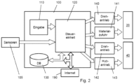
- Fig.1 shows an injection molding compounder 1 in which an extruder unit 20 is connected to an injection molding unit 40 in such a way that the plastic material liquefied in the extruder 20 is fed into the injection molding unit.
- the extruder has the task of producing the plastic melt and achieving a certain mixing of the different components. As will be explained in more detail below, the quality or uniformity of the mixing achieved in the extruder does not have to be as high as is required for the injection process, since the melt provided by the extruder is fed into the injection unit, where further additional mixing and increased homogeneity takes place.
- the extruder or extruder unit is also referred to as a compounder and is used as such.
- One advantage of an injection molding compounder is that the plastic mixture required in the injection unit is produced in a simultaneous process in the extruder.
- the conventional production of compound granules can be omitted, thus saving the energy required to re-melt the granules and avoiding the stress on the material caused by granulation and the associated damage to the material.
- the housing of the injection unit 40 has a melt inlet 48, which is connected to the extruder outlet 28, as the outlet of the melt from the extruder.
- the melt inlet 48 is a connection attached to the injection housing 41, preferably welded, to which a pipe can be attached in a pressure-tight manner.
- a pipe connection 35, which has a valve 30, is provided as a connection between the extruder outlet 28 and the melt inlet 48.
- the injection unit 40 has an injection nozzle 49 at the outlet end, which is connected to one mold half of the injection molding tool 50.
- the melt inlet is as far away as possible from the injection nozzle 49, so that as large a part of the screw of the injection unit 40 as possible can be used for melt mixing.
- a certain distance is provided from the melt inlet 48 to the filling opening 42 so that a backflow of material in the direction of the filling opening 42 can be prevented.
- This distance from the melt inlet to the filling opening 42 is at least one screw thread, whereby the backflow can occur especially with the injection screw in the forward position.
- the distance can be two screw threads and in particular three screw threads. Since degassing can take place through the filling opening 42, the distance should not be chosen to be too large.
- a vacuum can be applied to the filling opening 42 for degassing.
- the inner diameter of the pipe connection 35 and thus also of the melt inlet 48 is dimensioned such that the injection unit can only be filled via the extruder.
- this inner diameter can be identical to the melt cross-section within the injection unit.
- the melt cross-section is defined as the area of the inner diameter of the injection housing 41 minus the cross-section of the injection screw 40.
- one or more plastic materials are fed to the extruder 20 via the filling opening 22 and It is melted and mixed by heating.
- further filling openings (not shown) can be provided.
- the valve 30 integrated into the pipe can be brought into a closed position in which the melt is prevented from flowing out of the extruder.
- the valve 30 can initially be closed until the plastic material in the extruder is sufficiently heated and homogenized. Plastic with inadequate properties can be released into the environment when the valve is in the discharge position.
- the valve is preferably a controlled valve that can be brought into a desired position via a drive, such as an electric, pneumatic or hydraulic drive.
- the valve also serves to quickly and cleanly switch from one material to the next. Material that may have been in the extruder 20 for too long when the compounder started up and could thus have degenerated, or that has been mixed during a material change, can be discharged to the outside via the open position of the valve.
- the melt inlet 48 is provided in the area of the injection unit 40 remote from the injection nozzle 49, so that the melt that is introduced into the injection unit 40 via the melt inlet is guided along a considerable part of the injection screw 44 on the way to the injection nozzle 49 and is further homogenized on this path.
- the injection screw 44 which is a pusher screw, is axially displaceable within the injection housing and the effective length h is defined in the retracted state, i.e. in the position remote from the injection nozzle 49.
- the position of the melt inlet is preferably in the range of 0.85 h +/- 0.15 h from the injection nozzle.
- the melt inlet can also be further away from the injection nozzle than the far end of the screw flights. In this case, the melt is guided over the entire length of the flights of the injection screw 44 and the best possible mixing of the melt on the injection unit side is achieved.
- the injection molding compounder can have a commercially available injection molding unit as the injection unit 40, which has been expanded to include the melt inlet 48 and also has one (or more) filling opening(s) 42 for the plastic granulate. These filling opening(s) 42 are not required or used when the injection molding unit is used as an injection molding compounder in the initially described embodiment of the injection molding compounder.
- injection screws are often 3-zone screws, they have an intake zone that makes up about 50% of the screw length, followed by the compression and metering zones (25% each). Due to the described position of the melt inlet, the melt is fed to the screw in the low-pressure area and the melt is preferentially guided along the entire compression and metering zone.
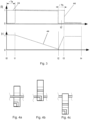
- Fig.3 The timing of an injection molding cycle is determined by Fig.3 .
- the rotary drive R of both the extruder screw 24 (in dotted line) and the injection screw 44 (in dashed line) is shown.
- the value “0” means that the corresponding drive is switched off and "1" means that the drive is switched on, but this does not mean that the drives have to be operated at the same rotation speed.
- the lower area of the Fig.3 shows the stroke of the injection screw, where the value "1" means that the injection screw 44 is in its front position, such as immediately after the injection process, and with the value "0" the injection screw is in the retracted position, in which a volume for the melt to be injected is created between the front end of the screw and the injection nozzle 49.
- the extruder screw 24 is started at time t0 and the melt is produced, mixed and homogenized in the extruder.
- the valve 30 can be closed.
- the valve 30 can be moved to the pass-through position at time t1 so that the melt can be discharged into the injection unit 40.
- the drive of the injection screw 44 is started, resulting in a time offset of the switch-on times ⁇ Ta of both screws.
- the injection screw is in its front position.
- both the extruder and injection screws are driven and melt is generated, and the injection screw 44 is moved into the retracted position and the melt collects in front of the injection screw 44 for the next injection process.
- a sufficient amount of melt has been generated for the injection movement taking place in the time range from t2 to t3.
- the extruder screw 24 is stopped and the lifting drive 143 of the injection unit 40 is activated.
- the injection screw has advanced to its front position and the injection of the plastic into the injection mold has ended, so that the rotary drive of the injection screw 44 can be stopped. There is thus a time offset of ⁇ Tb between the switching off of the two rotary drives.
- the rotary drive of the extruder screw is switched off at the same time as the lifting drive of the injection screw 44 is switched on, but alternatively the extruder screw can only be switched off at time t2', so that in the period t2 to t2' the lifting drive of the injection screw 44 and the rotary drive of the extruder screw are activated simultaneously and melt continues to be fed into the injection unit during the injection process of the plastic into the tool.
- the melt inlet 48 is provided in the rear area of the injection unit, i.e. away from the injection nozzle, and there is a lower pressure there than in the front area.
- the injection process is finished and the rotary drives of the injection screw 44 and the extruder screw are switched off during the curing and cooling time of the melt in the injection mold.
- the molded plastic workpiece is removed from the mold.
- the next injection molding cycle can begin, so that time t4 is identical to t0 of the next cycle.
- the extruder screw 24 can be reactivated during the cooling time, i.e. the range from t3 to t4, and produce melt for the next cycle, thereby reducing the cycle time.
- a holding pressure is preferably applied in the time period t3 to t4 via the stroke of the injection screw to compensate for the shrinkage of the injected plastic.
- the injection molding compounder is particularly suitable for applications where different materials are to be mixed together. Since the mixing takes place in both the extruder and the injection unit, the respective residence and mixing times and their extent in both of these units are reduced and overall, with good mixing, the thermal and mechanical stress on the materials is reduced.
- Suitable materials include a mixture of polycarbonate (PC) and acrylonitrile-butadiene-styrene (ABS), which is very sensitive to long-term temperature influences and high temperatures.
- PC polycarbonate
- ABS acrylonitrile-butadiene-styrene
- PP polypropylene
- talc 20% talc
- the impact strength can be increased by adding glass fibers or other fibers.
- the shortened residence time of the melt in each of these units reduces the mechanical stress on the fibers and reduces the risk of fiber breakage, thus increasing the strength of the molded part produced.
- a stable (lightweight) material can be produced by adding peroxide crosslinkers to polyethylene PE.
- Various types of fibers can be used as fibers, such as glass fibers, carbon fibers or natural fibers.
- the usual average residence time of the plastic is 2 to 6 minutes and the combined total residence time in the injection molding compounder can be reduced due to the better mixing within the extruder. Residence times that are too long can cause thermal and thermo-oxidative material damage.
- the injection molding compounder comprises a computer unit or a programmable logic controller PLC 100 or is connected to it.
- the computer unit 100 comprises a control unit 120 which receives various input values via an input module 110, which is provided with a keyboard and a control screen, via various sensors 105 and/or via a memory module 130 and uses these to determine setpoints for the rotary drive 140 of the extruder 20 and the rotary drive 142 and the lifting drive 143 of the injection unit 40.
- Other existing setpoint generators such as for temperature control or the material supply for the extruder, are not discussed in more detail for the sake of brevity and clarity.
- Specifications for the operation of the injection molding compounder and in particular for switching the drives 140, 142 or 143 on and off can be entered directly via the input module 110.
- the sensors can act as a monitoring unit and detect and report blockages in the filling openings or signs of such and control the compounder accordingly.
- the extruder 20 can be operated with a bottom feed.
- the material feed 141 i.e. the dosing device of the extruder, determines the throughput of the extruder by limiting the material input via the hopper 22 with a feeding valve (not shown).
- This mode of operation differs from the overfeed mode, in which the material is fed "with a full hopper”. With bottom feed, the direct connection between the extruder screw speed and the throughput is eliminated. This makes it possible to control the preparation, e.g. the homogenization of the material in the extruder, via the extruder screw speed.
- injection units are generally not bottom fed. In this described mode of operation of the injection compounder, both advantages can be combined.
- one type of material can be fed in from a hopper 22, or several dosing stations can be provided which are operated in a coordinated manner so that a mixture is created when the material is filled into the extruder, or an additive, such as a dye or reinforcing fibers, is mixed into one or more plastic materials.
- control unit 120 can regulate the material feed 141 depending on the measured conditions, such as the filling level of the injection unit 40 or a time control.
- the dead time i.e. the delay from the control to the change in the material flow into the injection unit 40, must be taken into account, so that alternatively and/or additionally, a control of the rotary drive 140 of the extruder unit 20 can be used to increase the feed rate into the injection unit.
- the control unit 120 is set up to regulate the rotary drive 140 of the extruder to the nominal speed within 3 seconds (or max. 5s). This is an accelerated start-up compared to conventionally used start-up ramps of approx. 10s.
- the shutdown ramp i.e. the braking of the extruder to a standstill, has the same values or lower. According to one embodiment, these times can be used in particular with a cycle time of approx. 30s for an injection process.
- the storage module 130 can also have a database that contains empirical values for controlling the injection molding compounder depending on different materials or material combinations.
- the empirical values can, for example, include data that the viscosity of a first material composition A is lower than that of another material composition B and can therefore contain changed time specifications for the drives. For example, with a lower viscosity, it is easier to introduce additional material into the injection unit during the injection process and the time period t2 to t2' can therefore be selected to be longer than with a less viscous material composition. Accordingly, the times t1, t2 or t3 in particular are stored in a database for different material compositions.
- the operating parameters of the injection molding compounder can be calculated from the values stored in the database depending on different system variables such as the size, design or delivery volume of the extruder or injection unit, the desired or required temperature profiles or the size/mass of the injection molded part to be produced.
- the control unit preferably also has a memory function for storing operating parameters in the database so that the user can enter values via the input module 110 and recall them at a later time to control the injection molding compounder.
- the computer unit 100 can act as a stand-alone controller to drive and control both the injection unit 40 and the extruder.
- a controller already present on the injection unit 40 or the extruder unit 20 can be used to generate setpoints for the other unit 40, 20.
- control unit 120 is connected to the Internet 190.
- remote maintenance of the injection molding compounder via this connection, i.e. to read out parameters about the operating state and transmit them to a central control point, evaluate them there and send new target values and control conditions or algorithms to the control unit.
- a central database with advantageous operating conditions and machine settings in relation to special materials or material mixtures for the injection molding compounder can be provided at a location with access to the Internet (web server).
- the control unit 120 accesses this web server, reads out these advantageous or recommended operating conditions and stores them in the internal database 130 in order to be able to subsequently suggest them to the user as setting parameters.
- Fig.4 consists of the figures Fig. 4a, 4b and 4c , which schematically show different control states of the valve 30, which is preferably a heated 3-way valve.
- the extruder side is shown on the left and the injection unit side on the right, so that in the conveying process described above the melt is guided from left to right through the valve.
- This state is shown in Fig. 4a shown.
- Fig. 4c shows the valve in the closed state.
- This can be useful during the plasticizing phase of the plastic in the extruder 20 in order to be able to control the valve in this state, for example in the period from t0 to t1 (see Fig.3 ) to prevent the conveyance of insufficiently homogenized melt to the injection unit 40.
- the valve 30 can be brought into the discharge position, which in Fig. 4b
- the valve 30 can thus be used as a start-up valve and can also be used as a safety valve in the event of overpressure.
- the injection molding compounder and in particular the extruder 20, the transition of the pipe connection 35 from the extruder 20 to the injection unit 40 and the injection unit 40 is a system closed to the outside environment, although openings such as for degassing can be provided.
- the supply of the plastic components, the additives, the fillers and/or the fibers preferably takes place in the extruder and in the injection unit no further material is preferably added to the melt
- other materials such as glass fibers, natural fibers, peroxide crosslinkers, polylactic acid (PLA) or other plastic materials can also be added via one or more filling openings 42 of the injection unit. The latter is particularly advantageous if the added materials are (temperature) sensitive and possible damage in the extruder is to be avoided.
- the extruder described in the above exemplary embodiment is a single-screw extruder. It is known to those skilled in the art that, in general, a better mixing result can be achieved with a two- or multi-screw extruder than with a single-screw extruder. However, the multi-screw extruder also causes a higher mechanical load on the material, which causes a reduced chain length of the monomers (or polymers) or the fibers and can therefore cause a reduced component strength. Since the mixing result achieved by the (single-screw) extruder is further increased by the subsequent passage of the melt through the injection unit, a higher component quality can be achieved with the (single-screw) extruder than with a multi- (e.g. two-) screw extruder.
- a multi-screw extruder can also be used and the mixing result achieved there can be further increased in the downstream injection unit.
- the longitudinal alignment of the extruder is according to Fig.1 at a 90° angle to the injection unit.
- the melt is thus diverted by 90° at the inlet valve in the transition to the longitudinal direction of the injection unit and the material flow of the melt is swirled and an improvement in mixing is achieved which is gentle on the material.
- the mixing can be further increased by a further (not shown) diversion of the melt flow.
- the extruder can be aligned parallel to the injection unit so that the pipe connection connected to the extruder outlet is first diverted in the direction of the melt inlet 48 and the melt flow is subsequently diverted a second time in the injection unit.
- a comparable result can be achieved if the extruder is arranged perpendicular to the injection unit and with a height offset from it.
Description
Die Erfindung betrifft einen Spritzgießcompounder gemäß dem Oberbegriff des Anspruchs 1, ein entsprechendes Verfahren zur Herstellung eines Spritzgußwerkstücks und ein Computerprogrammprodukt zur Steuerung eines entsprechenden Spritzgießcompounders.The invention relates to an injection molding compounder according to the preamble of
Herkömmlich ist bekannt, verschiedene Ausgangsmaterialien in einem Extruder zu einer homogenen Schmelze zu vermischen also sie zu compoundieren und die Schmelze dann zu granulieren, um sie zu einem späteren Zeitpunkt in einer Spritzgussmaschine zu verwenden. Den Zwischenschritt des Granulierens kann man mit einem bekannten Spritzgießcompounder vermeiden, bei dem die im Compounder oder Extruder hergestellte Kunststoffschmelze unmittelbar der Einspritzeinheit zugeführt wird.It is conventional to mix different starting materials in an extruder to form a homogeneous melt, i.e. to compound them, and then to granulate the melt in order to use it at a later date in an injection molding machine. The intermediate step of granulation can be avoided with a well-known injection molding compounder, in which the plastic melt produced in the compounder or extruder is fed directly to the injection unit.
So wird gemäß
Die
Als Werkstoffe werden thermoplastische Polymere oder Thermosetting-Polymere und Mischungen hiervon verwendet und dabei kommen organische oder anorganische oder faserförmige Füllstoffe oder Keramiken zum Einsatz. Einerseits ist es wichtig, eine gleichmäßige und homogene Durchmischung der Bestandteile zu erzielen. Andererseits sollte keine zu lang anhaltende oder zu umfangreiche Durchmischung durchgeführt werden, da sich hierdurch die Kettenlänge der Polymere reduzieren kann und ferner können faserförmige Füllstoffe brechen und dadurch die Festigkeit des hergestellten Spritzgusswerkstücks reduzieren.Thermoplastic polymers or thermosetting polymers and mixtures thereof are used as materials, and organic or inorganic or fibrous fillers or ceramics are used. On the one hand, it is important to achieve a uniform and homogeneous mixing of the components. On the other hand, mixing should not be carried out for too long or too extensively, as this can reduce the chain length of the polymers and fibrous fillers can break, thereby reducing the strength of the injection-molded workpiece produced.
Die Aufgabe der vorliegenden Erfindung ist es, einen Spritzgießcompounder bereitzustellen, bei dem mit möglichst geringem Aufwand eine ausreichend gute Durchmischung und eine möglichst geringe Schädigung der Kunststoffkomponenten durch die Durchmischung auftritt. Ferner soll der apparative Aufbau des Spritzgießcompounders möglichst einfach sein, so dass ggf. bei einem Kunststoffverarbeiter vorhandene Gerätschaften für den Spritzgießcompounder verwendet werden können und so die Investitionskosten gering sein können.The object of the present invention is to provide an injection molding compounder in which sufficiently good mixing and as little damage to the plastic components as possible through mixing occurs with as little effort as possible. Furthermore, the apparatus design of the injection molding compounder should be as simple as possible so that, if necessary, existing equipment at a plastics processor can be used for the injection molding compounder and the investment costs can be low.
Diese Aufgabe wird durch die Merkmale der unabhängigen Ansprüche gelöst. Bevorzugte Ausführungsformen ergeben sich aus den Unteransprüchen.This object is achieved by the features of the independent claims. Preferred embodiments emerge from the subclaims.
Ein Spritzgießcompounder weist einen Extruder mit zumindest einer in einem Extrudergehäuse angeordneten Extruderschnecke auf, eine Einspritzeinheit mit einer in einem Einspritzgehäuse angeordneten Einspritzschnecke, wobei die Einspritzeinheit eine von der Einspritzdüse der Einspritzeinheit bis zu dem davon entfernten Ende der Windungen der Einspritzschnecke definierte Wirklänge aufweist. Diese Wirklänge wird bevorzugt in der vorgeschobenen Position der Einspritzeinheit, also unmittelbar nach dem Einspritzvorgang, definiert. Dabei ist am Einspritzgehäuse ein Schmelzeeinlass vorgesehen, der mit einem Auslass des Extruders verbunden ist, wobei der Schmelzeeinlass weiter als ein Drittel der Wirklänge von der Einspritzdüse entfernt ist. Dabei wird die Richtung der Wirklänge bevorzugt in axialer Richtung der Einspritzeinheit gemessen. Ferner wird bevorzugt die Wirklänge dann betrachtet bzw. definiert, wenn die Einspritzschnecke oder die Schubschnecke in ihrer von der Einspritzdüse entfernten Lage ist. Durch den beschriebenen Aufbau wird die Schmelze, die von dem Extruder erzeugt wurde, zumindest entlang eines Teils der Einspritzschnecke geleitet und wird dort und dabei weiter durchmischt und weiter homogenisiert. Aus diesem Grund kann die Durchmischung und Homogenisierung innerhalb des Extruders lediglich eine Teildurchmischung oder Teilhomogenisierung sein, die für den eigentlichen Spritzprozess noch nicht ausreicht. In der Kombination mit der weiteren Homogenisierung und Durchmischung in der Einspritzeinheit wird die benötigte Materialqualität erzielt. Neben dem systeminhärenten Vorteil eines Spritzgießcompounders, dass ein Compound in einem einzigen Herstellprozess hergestellt und unmittelbar danach verarbeitet wird, ergibt sich der Vorteil einer schonenden Behandlung des Kunststoffmaterials. Es wird nämlich durch die verteilte Bearbeitung der Schmelze eine in der Summe reduzierte mechanische Belastung auf das Material ausgeübt und die Kettenlänge der Kunststoffmoleküle wird so nicht übermäßig reduziert und entsprechend wird auch die Faserlänge von zugefügten Fasern nicht (z.B. durch Faserbruch) reduziert. Wenn die Schmelze über weniger als einem Drittel der Wirklänge innerhalb der Einspritzeinheit geführt wird, kommen die Vorteile der nachfolgenden Durchmischung nicht ausreichend zum Tragen. Auch wird vermieden, dass in der Schmelze nicht aufgeschlossene bzw. nicht ausreichend aufgeschmolzene Kunststoffpartikel vorhanden sind, die zum einen die mechanischen Formteileigenschaften stark reduzieren würden und zum anderen den Dosierprozess destabilisieren würden und Drehmoment- und Dosierzeitschwankungen verursachen und einen Verschleiß an der Schnecke oder der Rückstromsperre führen können.An injection molding compounder has an extruder with at least one extruder screw arranged in an extruder housing, an injection unit with an injection screw arranged in an injection housing, the injection unit having an effective length defined from the injection nozzle of the injection unit to the end of the turns of the injection screw remote therefrom. This effective length is preferably defined in the advanced position of the injection unit, i.e. immediately after the injection process. A melt inlet is provided on the injection housing, which is connected to an outlet of the extruder, the melt inlet being more than a third of the effective length away from the injection nozzle. The direction of the effective length is preferably measured in the axial direction of the injection unit. Furthermore, the effective length is preferably considered or defined when the injection screw or the pusher screw is in its position remote from the injection nozzle. Due to the described structure, the melt produced by the extruder is guided along at least part of the injection screw and is further mixed and homogenized there and in the process. For this reason, the mixing and homogenization within the extruder can only be partial mixing or partial homogenization, which is not yet sufficient for the actual injection process. In combination with the further homogenization and mixing in the injection unit, the required material quality is achieved. In addition to the system-inherent advantage of an injection molding compounder that a compound is produced in a single production process and processed immediately afterwards, there is the advantage of gentle treatment of the plastic material. The distributed processing of the melt results in a reduced overall mechanical Stress is exerted on the material and the chain length of the plastic molecules is not excessively reduced and the fiber length of added fibers is not reduced accordingly (e.g. due to fiber breakage). If the melt is guided over less than a third of the effective length within the injection unit, the advantages of the subsequent mixing are not sufficiently realized. It is also avoided that there are plastic particles in the melt that have not been broken down or have not melted sufficiently, which would on the one hand greatly reduce the mechanical properties of the molded part and on the other hand destabilize the dosing process and cause torque and dosing time fluctuations and can lead to wear on the screw or the non-return valve.
Bevorzugt weist der Extruder exakt eine Extruderschnecke auf. Aufgrund der Fließstrecke der Schmelze nach dem Verlassen des Extruders entlang zumindest eines Teils der Einspritzschnecke wird die Schmelze dort weiter durchmischt. Dadurch kann es ausreichend sein, dass ein Einschneckenextruder verwendet wird, in dem das Material schonender bearbeitet und dabei zwar auch weniger homogenisiert wird, aber dieser Nachteil wird durch die weitere Durchmischung innerhalb Einspritzeinheit aufgewogen.The extruder preferably has exactly one extruder screw. Due to the flow path of the melt after leaving the extruder along at least part of the injection screw, the melt is further mixed there. It may therefore be sufficient to use a single-screw extruder in which the material is processed more gently and is also less homogenized, but this disadvantage is offset by the further mixing within the injection unit.
Insbesondere kann der Schmelzeeinlass weiter als die Hälfte der Wirklänge von der Einspritzdüse und bevorzugt weiter als zwei Drittel der Wirklänge von der Einspritzdüse entfernt sein. Hiermit wird die Länge definiert, die die Schmelze innerhalb der Einspritzeinheit geleitet wird und ein längerer Schmelzeweg erhöht die Durchmischung und Homogenisierung.In particular, the melt inlet can be further than half the effective length from the injection nozzle and preferably further than two thirds of the effective length from the injection nozzle. This defines the length that the melt is guided within the injection unit and a longer melt path increases mixing and homogenization.
Weiterführend ist eine Steuerung eingerichtet, um den (Dreh-)antrieb der Extruderschnecke in Abhängigkeit von der Zyklusphase eines Einspritzvorgangs ein- und auszuschalten, wobei insbesondere innerhalb des Zyklus des Einspritzvorgangs eine Zeitspanne des aktivierten Antriebs der Extruderschnecke und eine Zeitspanne des nicht-aktivierten Antriebs der Extruderschnecke vorgesehen ist. Gerade bei einem Einschneckenextruder ist es technisch einfach möglich, den Extruder zu starten und zu stoppen und so die zu jedem Zeitpunkt benötigte Schmelze bereitzustellen.Furthermore, a control system is set up to switch the (rotary) drive of the extruder screw on and off depending on the cycle phase of an injection process, whereby a period of time in which the drive of the extruder screw is activated and a period of time in which the drive of the extruder screw is not activated is provided within the cycle of the injection process. Especially with a single-screw extruder, it is technically easy to start and stop the extruder and thus provide the melt required at any time.
Bevorzugt ist eine Steuerung vorgesehen, um den Antrieb der Extruderschnecke in Abhängigkeit von der Zyklusphase eines Einspritzvorgangs und/oder dem Füllgrad der Einspritzeinheit ein- und auszuschalten. So wird eine funktionelle Kopplung zwischen der Einspritzschnecke und der Extruderschnecke erzielt. In diesem Sinne kann der Fördervolumenstrom der Extruderschnecke an das von der Einspritzeinheit bei der Rückbewegung der Einspritzschnecke aufnehmbare Volumen der Schmelze angepasst werden. Dieses kann als eine einfache Steuerung geschehen, in dem Sinne, dass in Abhängigkeit von Zykluszeitpunkten des Einspritzvorgangs der Extruder ein- (oder aus-) - geschaltet wird. Alternativ oder zusätzlich können an der Einspritzeinheit Sensoren, wie z.B. Drucksensoren, vorgesehen sein, die den Materialbedarf der Einspritzeinheit bestimmen und durch ein zeitgenaues Einschalten (oder Ausschalten) die benötigte Materialmenge von dem Extruder für die Einspritzeinheit bereitstellen lassen. Da die Rohrverbindung zwischen beiden Komponenten zu jedem Zeitpunkt gleichmäßig bzw. komplett mit Schmelze gefüllt ist, wird die Einspritzeinheit exakt mit der Schmelzemenge versorgt, die von dem Extruder bereitgestellt wird.Preferably, a control is provided to switch the drive of the extruder screw on and off depending on the cycle phase of an injection process and/or the filling level of the injection unit. In this way, a functional coupling between the injection screw and the extruder screw is achieved. In this sense, the delivery volume flow of the extruder screw can be adapted to the volume of melt that the injection unit can absorb during the return movement of the injection screw. This can be done as a simple control in the sense that the extruder is switched on (or off) depending on the cycle times of the injection process. Alternatively or additionally, sensors such as pressure sensors can be provided on the injection unit, which determine the material requirements of the injection unit and allow the extruder to provide the required amount of material for the injection unit by switching them on (or off) at the exact time. Since the pipe connection between both components is always evenly or completely filled with melt, the injection unit is supplied with exactly the amount of melt provided by the extruder.
Insbesondere kann die Steuerung eingerichtet sein, den von dem Extruder geförderten Volumenstrom der Schmelze an die Einspritzeinheit in Abhängigkeit von einer Abweichung eines einspritzphasenabhängig vorgegebenen Soll-Füllgrades zu einem gemessenen Ist-Füllgrad der Einspritzeinheit zu regeln. Dabei sind der Einspritzeinheit für das Befüllen bzw. die Befüllgeschwindigkeit Soll-Parameter vorgegeben, zu welchen Zeitpunkten die Einspritzschnecke an welcher axialen Position sein soll. Das Verschieben der Einspritzschnecke beim Befüllen ergibt sich direkt durch das Fördervolumen des Extruders. Wenn eine Abweichung der Ist-Befüllgeschwindigkeit zu vorgegebenen Sollwerten auftritt, so kann das Fördervolumen der Extruderschnecke im Sinne eines Regelkreises entsprechend angepasst werden.In particular, the control system can be set up to regulate the volume flow of melt delivered by the extruder to the injection unit depending on a deviation between a target filling level specified depending on the injection phase and a measured actual filling level of the injection unit. Target parameters are specified for the injection unit for filling or the filling speed, which specify at which times the injection screw should be in which axial position. The displacement of the injection screw during filling is a direct result of the delivery volume of the extruder. If there is a deviation between the actual filling speed and the specified target values, the delivery volume of the extruder screw can be adjusted accordingly in the sense of a control loop.
Insbesondere ist die Steuerung eingerichtet, den Drehantrieb der Einspritzschnecke und den Drehantrieb der Extruderschnecke ein- und auszuschalten, wobei für das Einschalten des Drehantriebs der Extruderschnecke ein zeitlicher Vorlauf oder eine Verzögerung oder insbesondere eine Gleichzeitigkeit gegenüber dem Einschalten des Drehantriebs der Einspritzschnecke oder gegenüber dem Einspritzhub der Einspritzschnecke vorgesehen ist. Bevorzugt ist für das Ausschalten des Drehantriebs der Extruderschnecke ein zeitlicher Vorlauf oder eine Verzögerung oder eine Gleichzeitigkeit gegenüber dem Ausschalten des Antriebs der Einspritzschnecke vorgesehen. Dies umfasst insbesondere auch, dass die Extruderschnecke synchron mit dem Drehantrieb der Einspritzschnecke betrieben werden kann. Aufgrund der Abstimmung der Antriebe von dem Extruder und der Einspritzeinheit kann in Abhängigkeit von dem verwendeten Material oder Compound eine Durchmischung und Verarbeitungsbedingungen erzielt werden, die optimal auf eine kurze Zykluszeit, eine gute Durchmischung und eine geringe Materialbelastung abgestimmt sind.In particular, the control system is designed to switch the rotary drive of the injection screw and the rotary drive of the extruder screw on and off, with a time lead or a delay or in particular a simultaneity being provided for switching on the rotary drive of the extruder screw compared to switching on the rotary drive of the injection screw or compared to the injection stroke of the injection screw. Preferably, a time lead or a delay or a simultaneity is provided for switching off the rotary drive of the extruder screw compared to switching off the drive of the injection screw. This also includes in particular that the extruder screw can be operated synchronously with the rotary drive of the injection screw. Due to the coordination of the drives of the extruder and the injection unit, mixing and processing conditions can be achieved depending on the material or compound used that are optimally tailored to a short cycle time, good mixing and low material load.
Bevorzugt sind ein Eingabe- und/oder ein Speichermodul zur Eingabe und/oder zur Speicherung von Betriebsparametern für die Antriebe der Einspritzschnecke und der Extruderschnecke vorgesehen, so dass Einspritzschnecke und die Extuderschnecke in Abhängigkeit von unterschiedlichen Werkstoffen oder Werkstoffkombinationen der Schmelze innerhalb eines Einspritzzyklus mit einem zeitlichen Versatz oder synchron zueinander betreibbar sind. Mit der Eingabeeinheit können gezielt Sollwerteingaben vorgenommen werden und das Speichermodul kann eine Datenbank mit unterschiedlichen vorteilhaften Betriebsbedingungen in Abhängigkeit von unterschiedlichen Werkstoffen aufweisen und es so dem Anwender erleichtern, den Spritzgießcompounder unter bestmöglichen Betriebsbedingungen zu verwenden.Preferably, an input and/or a storage module is provided for the input and/or storage of operating parameters for the drives of the injection screw and the extruder screw, so that the injection screw and the extruder screw can be operated with a time offset or synchronously with each other depending on different materials or material combinations of the melt within an injection cycle. Targeted setpoint inputs can be made with the input unit and the storage module can store a database with different advantageous operating conditions depending on of different materials, making it easier for the user to use the injection molding compounder under the best possible operating conditions.
Weiterführend ist zwischen dem Auslass des Extruders und dem Schmelzeeinlass der Einspritzeinheit ein Ventil angeordnet. Dieses ist ein Dreiwegeventil, welches alternativ die Schmelze in die Einspritzeinheit leitet oder an die Umgebung auslässt, und welches zusätzlich den Zustand des geschlossenen Ventils umfasst. Wenn das Ventil ein Überdruckventil ist, so kann ein von dem Extruder bereitgestellter zu hoher Schmelzedruck aus Sicherheitsgründen reduziert werden. Ein steuerbares Ventil kann während der Plastizierphase des Kunststoffs verhindern, dass die erzeugte Schmelze zu früh an die Einspritzeinheit abgegeben wird. Auch lassen sich Extruder und Einspritzeinheit einfach, schnell und sicher entkoppeln.Furthermore, a valve is arranged between the outlet of the extruder and the melt inlet of the injection unit. This is a three-way valve, which alternatively directs the melt into the injection unit or releases it into the environment, and which also includes the state of the closed valve. If the valve is a pressure relief valve, excessive melt pressure provided by the extruder can be reduced for safety reasons. A controllable valve can prevent the melt produced from being delivered to the injection unit too early during the plasticizing phase of the plastic. The extruder and injection unit can also be decoupled easily, quickly and safely.
Insbesondere ist der Ausgang des Extruders über eine druck- oder schmelzendichte Rohrverbindung mit dem Schmelzeeinlass der Einspritzeinheit verbunden und bevorzugt ist der Extruder eingerichtet, durch die Extruderschnecke Kunststoffschmelze zu der Einspritzeinheit zu fördern. Hier werden insbesondere keine weiteren Elemente zur Förderung, wie Kolben, Pumpen, Schnecken, der Nutzung der Schwerkraft oder dergleichen vorgesehen. Ausschließlich aufgrund der Fördereigenschaften des Extruders wird somit die erzeugte Schmelze zu der Einspritzeinheit gefördert und dort in einem Abschnitt der Schnecke eingespeist, in dem der Druck noch nicht sehr hoch ist. Bevorzugt wird die Schmelze somit nicht in den Granulattrichter der Einspritzeinheit eingeleitet.In particular, the outlet of the extruder is connected to the melt inlet of the injection unit via a pressure- or melt-tight pipe connection and the extruder is preferably set up to convey plastic melt to the injection unit through the extruder screw. In particular, no further conveying elements such as pistons, pumps, screws, the use of gravity or the like are provided here. The melt produced is thus conveyed to the injection unit solely on the basis of the conveying properties of the extruder and fed there into a section of the screw in which the pressure is not yet very high. The melt is therefore preferably not introduced into the granulate hopper of the injection unit.
Insbesondere ist zwischen dem Auslass des Extruders und dem Schmelzeeinlass der Einspritzeinheit für die Schmelze kein über eine Rohrverbindung hinausgehender Puffer vorgesehen und insbesondere ist kein Puffer mit einem veränderlichen Volumen vorgesehen, so dass die in dem Extruder erzeugte Schmelze direkt und unmittelbar an die Einspritzeinheit geleitet wird. Dieser Sachverhalt lässt sich auch folgendermaßen ausdrücken: Die Dauer eines Zyklus der Einspritzvorgänge ist in beliebig viele Zeitpunkte oder Zeitspannen unterteilbar, wobei bei jedem dieser Zeitpunkte der Volumenstrom der Rohrverbindung an jeder seiner Stellen zwischen dem Ausgang des Extruders und der Einspritzeinheit konstant ist. In diesem Sinne ist kein Puffer vorhanden, in dem sich solange die vom Extruder erzeugte Schmelze akkumuliert, bis die Einspritzeinheit diese Schmelze anfordert. Vielmehr fördert der Extruder direkt in die Einspritzeinheit. Dadurch wird die Standzeit der Schmelze in der Rohrverbindung reduziert und eine bessere Fertigungskontrolle erzielt. Auch lässt sich bevorzugt oder alternativ dieser Sachverhalt so ausdrücken, dass bei einem arbeitenden Spritzgießcompounder über mehrere Einspritzzyklen der Füllgrad der Rohrverbindung zwischen dem Ausgang des Extruders und der Einspritzeinheit unabhängig von der Zyklusphase der Einspritzeinheit gleichmäßig mit Schmelze gefüllt ist.In particular, there is no buffer for the melt beyond a pipe connection between the outlet of the extruder and the melt inlet of the injection unit, and in particular there is no buffer with a variable volume so that the melt produced in the extruder is fed directly and immediately to the injection unit. This fact can also be expressed as follows: the duration of a cycle of the injection processes can be divided into any number of points in time or time periods, with the volume flow of the pipe connection being constant at each of these points in time between the outlet of the extruder and the injection unit. In this sense, there is no buffer in which the melt produced by the extruder accumulates until the injection unit requests this melt. Instead, the extruder feeds directly into the injection unit. This reduces the service life of the melt in the pipe connection and achieves better production control. Preferably or alternatively, this fact can also be expressed in such a way that, in a working injection molding compounder, over several injection cycles, the filling level of the pipe connection between the outlet of the extruder and the injection unit is evenly filled with melt, regardless of the cycle phase of the injection unit.
Somit ist zwischen dem Extruder und der Einspritzeinheit lediglich das mit dem Ventil versehene Verbindungsrohr vorgesehen. Dieses Rohr oder dieser Schmelzekanal ist somit so gestaltet, dass keine Schmelze sich in toten Ecken absetzten kann. Dadurch wird verhindert, dass Material crackt und sich Verunreinigungen bilden.This means that only the connecting pipe with the valve is provided between the extruder and the injection unit. This pipe or melt channel is designed in such a way that no melt can settle in dead corners. This prevents material from cracking and contamination from forming.
Bei der Verwendung des Spritzgießcompounders ist die Schmelze, die im Extruder entlang der Längsrichtung des Extruders gefördert wird, zumindest eine, vorzugsweise zumindest zwei Umlenkungen, insbesondere jeweils 90° Umlenkungen, vorgesehen, um die Schmelze in Richtung der Längsrichtung der Einspritzeinheit umzulenken. Jede Umlenkung stört das Strömungsprofil innerhalb der Rohrleitung und unterstützt so die Durchmischung, wobei eine Umlenkung schonender für die Kunststoffschmelze ist als eine Durchmischung mit mechanischen Widerständen, Drosseln, Prallwänden oder dergleichen. Das Verhältnis Länge zu Durchmesser der Extruderschnecke beträgt nach einer Ausführungsform mindestens ca. 20. Nach einer weiteren Ausführungsform liegt der Wert bevorzugt zwischen 18 und 40, insbesondere zwischen 20 und 30.When using the injection molding compounder, the melt that is conveyed in the extruder along the longitudinal direction of the extruder is provided with at least one, preferably at least two deflections, in particular 90° deflections each, in order to deflect the melt in the direction of the longitudinal direction of the injection unit. Each deflection disrupts the flow profile within the pipeline and thus supports mixing, whereby a deflection is gentler on the plastic melt than mixing with mechanical resistances, throttles, impact walls or the like. The ratio of length to diameter of the extruder screw is, according to one embodiment, at least approximately 20. According to another embodiment, the value is preferably between 18 and 40, in particular between 20 and 30.
Ein Verfahren zur Herstellung eines Spritzgusswerkstücks mit einem Spritzgießcompounder weist die Schritte auf des Zuführens von einem oder mehreren Spritzgussmaterial/-ien zu einem Extruder, des Herstellens einer Schmelze durch das Schmelzen und/oder das Mischen von dem einen oder den mehreren Spritzgussmaterial(-ein) in dem Extruder, des Zuführens der Schmelze durch eine Einlassöffnung einer Einspritzeinheit in die Einspritzeinheit, des Leitens der Schmelze in der Einspritzeinheit in Richtung zu einer mit einem Spritzgusswerkzeug verbundenen Einspritzdüse, wobei eine Einspritzschnecke der Einspritzeinheit eine über die axiale Länge der Windungen der Einspritzschnecke definierte Windungslänge aufweist und die Einlassöffnung derart an der Einspritzeinheit angeordnet ist, dass die Schmelze zumindest über ein Drittel der Windungslänge entlang den Windungen der Einspritzschnecke geleitet wird. Alternativ zur Windungslänge kann an dieser Stelle auch die oben bereits definierte Wirklänge betrachtet werden.A method for producing an injection molded workpiece with an injection molding compounder has the steps of feeding one or more injection molding materials to an extruder, producing a melt by melting and/or mixing the one or more injection molding materials in the extruder, feeding the melt through an inlet opening of an injection unit into the injection unit, guiding the melt in the injection unit in the direction of an injection nozzle connected to an injection molding tool, wherein an injection screw of the injection unit has a winding length defined over the axial length of the turns of the injection screw and the inlet opening is arranged on the injection unit in such a way that the melt is guided along the turns of the injection screw over at least a third of the winding length. As an alternative to the winding length, the effective length already defined above can also be considered at this point.
Bevorzugt ist innerhalb eines Zyklus der Herstellung des Spritzgusswerkstücks eine Phase vorgesehen, in der die Extruderschnecke des Extruders nicht angetrieben wird und bevorzugt wird in der Phase des Nicht-Antriebs der Extruderschnecke die Einspritzschnecke angetrieben. So wird vor und/oder während der Einspritzphase der Schmelze in das Werkzeug die weitere Bereitstellung von Schmelze in dem Extruder gestoppt.Preferably, within a cycle of production of the injection molded workpiece, a phase is provided in which the extruder screw of the extruder is not driven, and preferably the injection screw is driven in the phase in which the extruder screw is not driven. Thus, the further provision of melt in the extruder is stopped before and/or during the injection phase of the melt into the tool.
Ein entsprechender Spritzgießcompounder kann hergestellt werden, indem an einer Einspritzeinheit, insbesondere einer handelsüblich erhältlichen Einspritzeinheit, ein Schmelzeeinlass angebracht wird und mit einem Extruder, insbesondere einem handelsüblich erhältlichen Extruder, verbunden wird, wobei insbesondere der Spritzgießcompounder ohne Verwendung von an der Einspritzeinheit vorhandenen Einfüllöffnungen für das Kunststoffgranulat in herkömmlicher Weise weiter verwendbar ist. Die Einfüllöffnung, wie der Granulattrichter kann an der Einspritzeinheit verbleiben, so dass sie alternativ auch konventionell betreibbar ist. So kann ein Kunststoffverarbeitungsunternehmen auf bereits vorhandene Komponenten zurückgreifen und muss dabei nur geringfügige Anpassungsarbeiten vornehmen. Die Einspritzeinheit ist auch nach dem Anbau des Schmelzeeinlasses weiter unabhängig von dem Extruder als eine Einspritzeinheit verwendbar, wenn der Schmelzeeinlass mit bspw. einer Endkappe verschlossen wird.A corresponding injection molding compounder can be produced by attaching a melt inlet to an injection unit, in particular a commercially available injection unit, and connecting it to an extruder, in particular a commercially available extruder, in particular the injection molding compounder can continue to be used in the conventional way without using the filling openings for the plastic granulate on the injection unit. The filling opening, like the granulate funnel, can remain on the injection unit so that it can also be operated conventionally as an alternative. This means that a plastics processing company can use existing components and only has to make minor adjustments. Even after the melt inlet has been installed, the injection unit can continue to be used as an injection unit independently of the extruder if the melt inlet is closed with an end cap, for example.
Ein Computerprogrammprodukt ist in einen Programmspeicher ladbar und weist Programmbefehle auf, um alle Schritte eines der vorstehend aufgeführten Verfahren auszuführen, wenn das Programm ausgeführt wird. So kann der Programmspeicher eine Datenbank aufweisen, die in Abhängigkeit von Materialien oder Materialkombinationen Einstellparameter für den Extruder und die Einspritzeinheit aufweist, um materialabhängig die bestmögliche Steuerung des Spritzgießcompounders zu ermöglichen. Das Computerprogrammprodukt ist bspw. auf einem Computer oder einer SPS lauffähig. Auch kann es auf der Steuerung der Einspritzeinheit oder auf der Steuerung des Extruders oder kombiniert auf beiden miteinander verbundenen Steuerungen ausgeführt werden. Alternativ kann eine Steuerung hierfür verwendet werden, die unabhängig von den genannten Steuerungen ist.A computer program product can be loaded into a program memory and has program instructions to carry out all the steps of one of the methods listed above when the program is executed. The program memory can have a database that has setting parameters for the extruder and the injection unit depending on materials or material combinations in order to enable the best possible control of the injection molding compounder depending on the material. The computer program product can run on a computer or a PLC, for example. It can also be run on the control of the injection unit or on the control of the extruder, or combined on both interconnected controls. Alternatively, a control can be used for this that is independent of the controls mentioned.
Im Folgenden wird eine bevorzugte Ausführungsform anhand von Figuren beispielhaft beschrieben. Es zeigen:
- Fig. 1
- einen schematischen Aufbau eines Spritzgießcompounders mit einer Extruder- und einer Einspritzeinheit,
- Fig. 2
- ein schematisches Diagramm der Steuerung des Spritzgießcompounders,
- Fig. 3
- ein Diagramm der zeitlichen Abfolge des Antriebs R der Drehantriebe und des Hubs der Einspritzschnecke und
- Fig. 4
- eine schematische Darstellung der Schaltstellungen des
Dreiwegeventils 30.
- Fig.1
- a schematic structure of an injection molding compounder with an extruder and an injection unit,
- Fig.2
- a schematic diagram of the injection molding compounder control system,
- Fig.3
- a diagram of the timing of the drive R of the rotary drives and the stroke of the injection screw and
- Fig.4
- a schematic representation of the switching positions of the three-
way valve 30.
Das Gehäuse der Einspritzeinheit 40 weist einen Schmelzeeinlass 48 auf, der mit dem Extruderauslass 28, als dem Auslass der Schmelze aus dem Extruder, verbunden ist. Der Schmelzeeinlass 48 ist ein an dem Einspritzgehäuse 41 befestigter, bevorzugt verschweißter Anschluss, an dem ein Rohr druckdicht befestigt werden kann. Als Verbindung zwischen dem Extruderauslass 28 und dem Schmelzeeinlass 48 ist eine Rohrverbindung 35 vorgesehen, die ein Ventil 30 aufweist. Die Einspritzeinheit 40 weist am ausgangsseitigen Ende eine Einspritzdüse 49 auf, die mit einer Formhälfte des Spritzgießwerkzeugs 50 verbunden ist. Der Schmelzeeinlass ist zum einen möglichst weit von der Einspritzdüse 49 entfernt, so dass ein möglichst großer Teil der Schnecke der Einspritzeinheit 40 für die Schmelzedurchmischung genutzt werden kann. Zum anderen ist von dem Schmelzeinlass 48 ein gewisser Abstand zu der Einfüllöffnung 42 vorgesehen, dass ein Materialrückfluss in Richtung der Einfüllöffnung 42 verhindert werden kann. Diese Entfernung von dem Schmelzeeinlass zu der Einfüllöffnung 42 beträgt zumindest einen Schneckengang, wobei der Rückfluss v.a. bei der Einspritzschnecke in der nach vorne gefahrenen Position erfolgen kann. Bevorzugt kann der Abstand zwei Schneckengänge betragen und insbesondere drei Schneckengänge. Da durch die Einfüllöffnung 42 eine Entgasung stattfinden kann, sollte der Abstand nicht zu groß gewählt werden. Zur Entgasung kann an der Einfüllöffnung 42 ein Vakuum angelegt werden.The housing of the
Der Innendurchmesser der Rohrverbindung 35 und somit auch des Schmelzeeinlasses 48 ist so bemessen, dass die Einspritzeinheit ausschließlich über den Extruder befüllbar ist. So kann bspw. bei einer Auslegung des Compounders mit gleichen Drehzahlen und gleichen Windungssteigung von beiden Schnecken dieser Innendurchmesser identisch zum Schmelzequerschnitt innerhalb der Einspritzeinheit sein. Der Schmelzequerschnitt ist dabei als die Fläche des Innendurchmessers des Einspritzgehäuses 41 abzüglich dem Querschnitt der Einspritzschnecke 40 definiert.The inner diameter of the
Bei der Verwendung des Spritzgießcompounders werden dem Extruder 20 über die Einfüllöffnung 22 ein oder mehrere Kunststoffmaterialien zugeführt und in ihm über eine Erwärmung geschmolzen und gemischt. Neben der einen gezeigten Einfüllöffnung 22 können weitere Einfüllöffnungen (nicht dargestellt) vorgesehen sein.When using the injection molding compounder, one or more plastic materials are fed to the
Die Kunststoffschmelze verlässt den Extruder an dem Extruderauslass 28 und wird über die Rohrverbindung 35 in die Einspritzeinheit gefördert. Das in die Rohrleitung integrierte Ventil 30, ist in eine geschlossene Stellung bringbar, in der der Ausfluss der Schmelze aus dem Extruder verhindert wird. So kann zu Beginn des Verarbeitungsprozesses das Ventil 30 zunächst geschlossen sein, bis das Kunststoffmaterial im Extruder ausreichend erhitzt und homogenisiert ist. Kunststoff mit unzureichenden Eigenschaften kann in der ablassenden Stellung des Ventils an die Umgebung abgegeben werden. Das Ventil ist bevorzugt ein gesteuertes Ventil, das über einen Antrieb, wie einem elektrischen, pneumatischen oder hydraulischen Antrieb in eine Sollposition bringbar ist. Das Ventil dient neben Sicherheitsaspekten auch einer raschen und sauberen Umstellung von einem Material zu einem nächsten. Material, welches beim Anlaufen des Compounders ggf. zu lange im Extruder 20 befindlich war und so degeneriert sein könnte, oder bei einer Materialumstellung vermischt ist, kann über die Öffnungsstellung des Ventils nach außen abgeleitet werden.The plastic melt leaves the extruder at the
Der Schmelzeeinlass 48 ist in dem von der Einspritzdüse 49 entfernten Bereich der Einspritzeinheit 40 vorgesehen, so dass die Schmelze, die über den Schmelzeeinlass in die Einspritzeinheit 40 eingeleitet wird, auf dem Weg zur Einspritzdüse 49 entlang einem beträchtlichen Teil der Einspritzschnecke 44 geleitet und auf diesem Weg weiter homogenisiert wird. Insbesondere ist es möglich, von dem äußeren Ende der Einspritzdüse in axialer Richtung der Einspritzeinheit bis zu dem von der Einspritzdüse 49 entfernten Ende der Windungen der Einspritzschnecke 44 eine Wirklänge h zu definieren. Die Einspritzschnecke 44, die eine Schubschnecke ist, ist innerhalb des Einspritzgehäuses axial verschiebbar und die Wirklänge h wird im zurückgefahrenen Zustand, also in der von der Einspritzdüse 49 entfernten Lage definiert. Die Lage des Schmelzeeinlasses ist bevorzugt im Bereich von 0,85 h +/- 0,15 h von der Einspritzdüse entfernt. Auch kann der Schmelzeeinlass weiter von der Einspritzdüse entfernt sein als das entfernte Ende der Schneckenwindungen. Im diesem Fall wird die Schmelze über die gesamte Länge der Windungen der Einspritzschnecke 44 geleitet und die bestmögliche einspritzeinheitsseitige Durchmischung der Schmelze erreicht.The
Wenn der Schmelzeeinlass zumindest zu 1/3 h von der Einspritzdüse entfernt ist, ergibt sich bereits eine nennenswerte zusätzliche Durchmischung der Schmelze in der Einspritzeinheit 40. Der Spritzgießcompounder kann als Einspritzeinheit 40 eine handelsübliche Spritzgußeinheit aufweisen, die um den Schmelzeeinlass 48 erweitert wurde und ferner eine (oder mehrere) Einfüllöffnung(en) 42 für das Kunststoffgranulat aufweisen. Diese Einfüllöffung(en) 42 werden bei der Verwendung der Spritzgußeinheit als Spritzgießcompounder bei der zunächst beschriebenen Ausführungsform des Spritzgießcompounders nicht benötigt und verwendet.If the melt inlet is at least 1/3 of the way from the injection nozzle, there is already a significant additional mixing of the melt in the
Da es sich bei Einspritzschnecken häufig um 3-Zonen-Schnecken handelt, haben sie eine Einzugszone, die ca. 50% der Schneckenlänge ausmacht, an die sich die Kompressions- und Meteringzone (je 25%) anschließt. Durch die beschriebene Lage des Schmelzeinlasses, wird die Schmelze der Schnecke im Niederdruckbereich zugeführt und bevorzugt die Schmelze entlang der gesamten Kompressions- und Meteringzone geleitet.Since injection screws are often 3-zone screws, they have an intake zone that makes up about 50% of the screw length, followed by the compression and metering zones (25% each). Due to the described position of the melt inlet, the melt is fed to the screw in the low-pressure area and the melt is preferentially guided along the entire compression and metering zone.
Der zeitliche Ablauf eines Spritzgußzykluses ergibt sich aus
Zu Beginn des Einspritzzyklus wird zunächst die Extruderschnecke 24 zu dem Zeitpunkt t0 gestartet und im Extruder wird die Schmelze hergestellt, durchmischt und homogenisiert. Zu diesem Zeitpunkt kann das Ventil 30 geschlossen sein. Sobald eine gewisse homogene Schmelzemenge hergestellt wurde, kann zum Zeitpunkt t1 das Ventil 30 auf die durchlassende Stellung gebracht werden, so dass die Schmelze in die Einspritzeinheit 40 abgegeben werden kann. Zu diesem Zeitpunkt wird der Antrieb der Einspritzschnecke 44 gestartet, so dass sich ein zeitlicher Versatz der Einschaltzeitpunkte ΔTa beider Schnecken ergibt. Die Einspritzschnecke befindet sich dabei in ihrer vorderen Position.At the beginning of the injection cycle, the
In der Zeitspanne von t1 bis t2 werden sowohl die Extruder- und Einspritzschnecke angetrieben und Schmelze wird erzeugt und dabei wird die Einspritzschnecke 44 in die zurückgefahrende Position gebracht und die Schmelze sammelt sich für den nächsten Einspritzvorgang vor der Einspritzschnecke 44. Zum Zeitpunkt t2 wurde eine ausreichende Schmelzemenge für die im Zeitbereich von t2 bis t3 stattfindende Einspritzbewegung erzeugt. Zum Zeitpunkt t2 wird die Extruderschnecke 24 gestoppt und der Hubantrieb 143 der Einspritzeinheit 40 aktiviert. Zum Zeitpunkt t3 hat sich die Einspritzschnecke in ihre vordere Position vorgeschoben und das Einspritzen des Kunststoffs in die Spritzgießform ist beendet, so dass der Drehantrieb der Einspritzschnecke 44 gestoppt werden kann. So besteht ein zeitlicher Versatz von ΔTb zwischen dem Ausschalten der beiden Drehantriebe.In the time period from t1 to t2, both the extruder and injection screws are driven and melt is generated, and the
Es ist nicht zwingend, dass, wie oben beschrieben, das Abschalten des Drehantriebs der Extruderschnecke zeitgleich mit dem Einschalten des Hubantriebs der Einspritzschnecke 44 stattfindet, sondern alternativ kann die Extruderschnecke erst zum Zeitpunkt t2' ausgeschaltet werden, so dass im Zeitraum t2 bis t2' gleichzeitig der Hubantrieb der Einspritzschnecke 44 und der Drehantrieb der Extruderschnecke aktiviert sind und während dem Einspritzvorgang des Kunststoffs in das Werkzeug weiter Schmelze in die Einspritzeinheit gefördert wird. Dies ist deshalb möglich, da der Schmelzeeinlass 48 im hinteren, also von der Einspritzdüse entfernten Bereich der Einspritzeinheit vorgesehen ist und dort ein niedrigerer Druck herrscht als im vorderen Bereich.It is not mandatory that, as described above, the rotary drive of the extruder screw is switched off at the same time as the lifting drive of the
Zum Zeitpunkt t3 ist der Einspritzvorgang beendet und die Drehantriebe der Einspritzschnecke 44 und der Extruderschnecke sind während der Aushärte- und Abkühlzeit der Schmelze in der Spritzgießform ausgeschaltet. Zum Zeitpunkt t4 wird das geformte Kunststoffwerkstück aus der Form entnommen. Zum Zeitpunkt t4 kann der nächste Spritzgießzyklus beginnen, so dass der Zeitpunkt t4 identisch zu t0 des nächsten Zyklus ist. Alternativ kann bereits während der Abkühlzeit, also dem Bereich von t3 bis t4 die Extruderschnecke 24 wieder aktiviert werden und Schmelze für den nächsten Zyklus herstellen und dadurch die Zyklusdauer reduzieren. Zusätzlich wird bevorzugt in der Zeitspanne t3 bis t4 über den Hub der Einspritzschnecke ein Nachdruck zum Ausgleich der Schwindung des eingespritzten Kunststoffs aufgebracht.At time t3, the injection process is finished and the rotary drives of the
Der Spritzgießcompounder eignet sich insbesondere für Einsatzgebiete, bei denen unterschiedliche Werkstoffe miteinander gemischt werden sollen. Da die Durchmischung sowohl in dem Extruder als auch in der Einspritzeinheit stattfindet, wird die jeweilige Verweil- und Durchmischungsdauer und deren Umfang in beiden dieser Einheiten reduziert und insgesamt wird bei einer guten Durchmischung die thermische und mechanische Belastung für die Werkstoffe reduziert.The injection molding compounder is particularly suitable for applications where different materials are to be mixed together. Since the mixing takes place in both the extruder and the injection unit, the respective residence and mixing times and their extent in both of these units are reduced and overall, with good mixing, the thermal and mechanical stress on the materials is reduced.
Als Materialien eignen sich bspw. eine Mischung von Polycarbonat (PC) und Acrylnitril-Budadien-Styrol (ABS), die sehr empfindlich gegen langen Temperatureinfluss und hohe Temperaturen ist. Auch kann Polypropylen (PP) mit bspw. 20% Talkum verwendet werden. Durch die Zugabe von Glasfasern oder anderen Fasern kann die Schlagzähigkeit erhöht werden. Durch die verkürzte Verweildauer der Schmelze in jeder dieser Einheiten wird die mechanische Belastung auf die Fasern reduziert und ein Brechen der Fasern reduziert und somit die Festigkeit des hergestellten Formstücks erhöht. Bei einem reaktiven Compoundieren kann durch die Zugabe von Peroxidvernetzern zu einem Polyethylen PE ein stabiles (Leichtbau-)Material hergestellt werden. Als Fasern kommen diverse Arten von Fasern in Betracht, wie Glasfasern, Kohlefasern oder Naturfasern. Bei herkömmlich bekannten allein stehenden Spritzgießmaschinen beträgt die übliche mittlere Verweilzeit des Kunststoffs bei 2 bis 6 Minuten und die kombinierte Gesamtverweilzeit in dem Spritzgießcompounder kann aufgrund der besseren Durchmischung innerhalb des Extruders reduziert werden. Zu lange Verweilzeiten können eine thermische und thermo-oxidative Materialschädigung verursachen.Suitable materials include a mixture of polycarbonate (PC) and acrylonitrile-butadiene-styrene (ABS), which is very sensitive to long-term temperature influences and high temperatures. Polypropylene (PP) with 20% talc, for example, can also be used. The impact strength can be increased by adding glass fibers or other fibers. The shortened residence time of the melt in each of these units reduces the mechanical stress on the fibers and reduces the risk of fiber breakage, thus increasing the strength of the molded part produced. In reactive compounding, a stable (lightweight) material can be produced by adding peroxide crosslinkers to polyethylene PE. Various types of fibers can be used as fibers, such as glass fibers, carbon fibers or natural fibers. In conventional stand-alone injection molding machines, the usual average residence time of the plastic is 2 to 6 minutes and the combined total residence time in the injection molding compounder can be reduced due to the better mixing within the extruder. Residence times that are too long can cause thermal and thermo-oxidative material damage.
Zu weniger als 20% wird üblicherweise die zum Schmelzen benötigte Energie über die Wärmebänder (nicht dargestellt) eingeleitet, sondern vielmehr über die Energie des Schneckenantriebs und der Reibung/Scherung in der Schmelze. Über den zweitstufigen Prozess der Herstellung der homogenen Schmelze erhält man eine Vielzahl von einstellbaren Betriebsparametern zur Erzielung einer guten Durchmischung bei einer kurzen Gesamtverweilzeit. Auch besteht bei einigen Kunststoffen, wie bspw. Polyamiden oder POM-Werkstoffen die Neigung, dass in der Kompressionszone einer Einspritzschnecke nicht ausreichend Energie zugeführt wird, so dass sich bei herkömmlichen Verfahren in der Einspritzschnecke ein Verschleiß verursachender Feststoffkeil bilden kann.Less than 20% of the energy required for melting is usually introduced via the heat belts (not shown), but rather via the energy of the screw drive and the friction/shear in the melt. The two-stage process of producing the homogeneous melt provides a variety of adjustable operating parameters to achieve good mixing with a short total residence time. With some plastics, such as polyamides or POM materials, there is also a tendency for insufficient energy to be supplied in the compression zone of an injection screw, so that with conventional processes a solid wedge can form in the injection screw, causing wear.
Im Folgenden wird auf die in
Der Extruder 20 ist mit einer Unterfütterung betreibbar. Bei dieser unterfütterten Betriebsweise gibt die Materialzuführung 141, also die Dosiereinrichtung des Extruders, den Durchsatz des Extruders dadurch vor, dass sie den Materialeintrag über den Trichter 22 mit einem Fütterungsventil (nicht dargestellt) begrenzt. Diese Betriebsweise unterscheidet sich von der überfütterten Betriebsweise, bei der "mit vollem Trichter" gespeist wird. Bei der Unterfütterung ist der unmittelbare Zusammenhang zwischen Extruderschneckendrehzahl und Durchsatz aufgehoben. Hierdurch wird es möglich, über die Extruderschneckendrehzahl die Aufbereitung, also z.B. die Homogenisierung des Materials im Extruder zu steuern. Um Lufteinschlüsse im gespritzten Produkt zu vermeiden werden Einspritzeinheiten i.d.R. nicht unterfüttert betrieben. In dieser beschriebenen Betriebsweise des Einspritzcompounders lassen sich also beide Vorteile kombinieren.The
Bei dem Zuführen von Material an den Extruder kann eine Materialsorte bzw. aus einem Trichter 22 zugefördert werden, oder es können mehrere Dosierstationen vorgesehen sein, die koordiniert betrieben werden, so dass beim Einfüllen in den Extruder eine Mischung erstellt wird, oder einem oder mehreren Kunststoffwerkstoffen ein Additiv, wie z.B. ein Farbstoff oder Verstärkungsfasern, zugemischt werden.When feeding material to the extruder, one type of material can be fed in from a
Ferner kann die Steuereinheit 120 in Abhängigkeit der gemessenen Zustände, wie z.B. Füllgrad der Einspritzeinheit 40 oder einer zeitlichen Steuerung die Materialzufuhr 141 regeln. Hierbei ist allerdings die Totzeit, also die Verzögerung von der Regelung zu der Veränderung des Materialflusses in die Einspritzeinheit 40 zu beachten, so dass alternativ und/oder zusätzlich eine Regelung des Drehantriebs 140 der Extrudereinheit 20 zur Erhöhung der Fördermenge in die Einspritzeinheit genutzt werden kann.Furthermore, the
Die Steuereinheit 120 ist eingerichtet den Drehantrieb 140 des Extruders innerhalb von 3 Sekunden (oder max. 5s) auf die Nenndrehzahl zu regeln. Dies ist ein beschleunigtes Anfahren im Vergleich zu herkömmlich verwendeten Anfahrrampen von ca. 10s. Die Abfahrrampe, also das Abbremsen des Extruders zum Stillstand, hat die gleichen Werte oder geringere. Diese Zeiten können nach einer Ausführungsform insbesondere bei einer Zykluszeit von ca. 30s eines Einspritzvorgangs genutzt werden.The
Auch kann das Speichermodul 130 eine Datenbank aufweisen, die in Abhängigkeit von unterschiedlichen Materialien oder Materialkombinationen Erfahrungswerte für die Steuerung des Spritzgießcompounders aufweist. Die Erfahrungswerte können beispielsweise Daten umfassen, dass bei einer ersten Materialzusammensetzung A die Viskosität niedriger ist, als bei einer anderen Materialzusammensetzung B und hieraus veränderte zeitliche Vorgaben für die Antriebe enthalten. So kann bei einer niedrigeren Viskosität bspw. besser auch während des Einspritzvorgangs weiteres Material in die Einspritzeinheit eingeleitet werden und somit die Zeitspanne t2 bis t2' größer gewählt werden als bei einer weniger viskosen Materialzusammensetzung. Entsprechend werden für unterschiedliche Materialzusammensetzungen insbesondere die Zeiten t1, t2 oder t3 in einer Datenbank abgelegt. Alternativ und/oder zusätzlich können aus den Werten, die in der Datenbank abgelegt sind, in Abhängigkeit von unterschiedlichen Systemvariablen wie der Größe, der Bauart oder dem Fördervolumen des Extruders oder der Einspritzeinheit, der gewünschten oder benötigten Temperaturverläufe oder der Größe/Masse des zu erzeugenden Spritzgussteils die Betriebsparameter des Spritzgießcompounders berechnet werden.The
Die Steuereinheit weist bevorzugt auch eine Speicherfunktion auf zum Speichern von Betriebsparametern in der Datenbank, so dass der Anwender über das Eingabemodul 110 Werte eingeben und diese zu einem späteren Zeitpunkt zur Steuerung des Spritzgießcompounders wieder abrufen kann.The control unit preferably also has a memory function for storing operating parameters in the database so that the user can enter values via the
Die Computereinheit 100 kann als allein stehende Steuerung sowohl die Einspritzeinheit 40 und den Extruder antreiben und steuern. Alternativ kann hierfür auch eine an der Einspritzeinheit 40 oder der Extrudereinheit 20 bereits vorhandene Steuerung genutzt werden, die Sollwerte für die jeweils andere Einheit 40, 20 erzeugt.The
Ferner besteht von der Steuereinheit 120 eine Verbindung mit dem Internet 190. Zum einen ist es möglich, über diese Verbindung eine Fernwartung des Spritzgießcompounders vorzunehmen, also Parameter über den Betriebszustand auszulesen und an eine zentrale Kontrollstelle zu übertragen, dort auszuwerten und neue Sollwerte und Steuerbedingungen oder -algorithmen an die Steuereinheit zu leiten. Ferner kann an einer Stelle mit Zugang zum Internet (Webserver) eine zentrale Datenbank mit vorteilhaften Betriebsbedingungen und Maschineneinstellungen in Bezug auf spezielle Materialien oder Materialmischungen für den Spritzgießcompounder vorgesehen sein. Die Steuereinheit 120 greift auf diesen Webserver zu, liest diese vorteilhaften bzw. empfohlenen Betriebsbedingungen aus und speichert sie in der internen Datenbank 130, um sie dem Anwender in der Folge als Einstellparameter vorschlagen zu können.Furthermore, the
Insgesamt ist der Spritzgießcompounder, und insbesondere der Extruder 20, der Übergang der Rohrverbindung 35 von dem Extruder 20 zu der Einspritzeinheit 40 und die Einspritzeinheit 40 ein gegen die Außenumgebung geschlossenes System, wobei allerdings Öffnungen wie z.B. zur Entgasung vorgesehen sein können.Overall, the injection molding compounder, and in particular the
Die Zufuhr von den Kunststoffbestandteilen, den Additiven, den Füllstoffen und/oder den Fasern geschieht bevorzugt in dem Extruder und in der Einspritzeinheit wird der Schmelze bevorzugt kein weiterer Stoff zugeführt. In alternativen Ausführungsformen können weitere Materialien, wie z.B. Glasfasern, Naturfasern, Peroxidvernetzer, Polylactic Acid (PLA) oder weitere Kunststoffmaterialien auch über eine oder mehrere Einfüllöffnungen 42 der Einspritzeinheit zugegeben werden. Letzteres ist insbesondere dann vorteilhaft, wenn die zugegebenen Materialien (temperatur-)empfindlich sind und eine mögliche Schädigung in Extruder vermieden werden soll.The supply of the plastic components, the additives, the fillers and/or the fibers preferably takes place in the extruder and in the injection unit no further material is preferably added to the melt In alternative embodiments, other materials such as glass fibers, natural fibers, peroxide crosslinkers, polylactic acid (PLA) or other plastic materials can also be added via one or
Der in der vorstehenden beispielhaften Ausführungsform beschriebene Extruder ist ein Einschneckenextruder. Es ist dem Fachmann bekannt, dass im Allgemeinen mit einem Zwei- oder Mehrschneckenextruder ein besseres Durchmischungsergebnis erzielt werden kann als mit einem Einschneckenextruder. Allerdings bewirkt der Mehrschneckenextruder auch eine höhere mechanische Belastung des Materials, was eine reduzierte Kettenlänge der Monomere (oder Polymere) oder der Fasern bewirkt und somit eine reduzierte Bauteilfestigkeit bewirken kann. Da das von dem (Einschnecken-)Extruder bewirkte Durchmischungsergebnis durch die nachgeschaltete Durchleitung der Schmelze durch die Einspritzeinheit weiter erhöht wird, kann mit dem (Einschnecken)-Extruder eine höhere Bauteilqualität als mit einem Mehr- (bspw. Zwei-) -schneckenextruder erzielt werden.The extruder described in the above exemplary embodiment is a single-screw extruder. It is known to those skilled in the art that, in general, a better mixing result can be achieved with a two- or multi-screw extruder than with a single-screw extruder. However, the multi-screw extruder also causes a higher mechanical load on the material, which causes a reduced chain length of the monomers (or polymers) or the fibers and can therefore cause a reduced component strength. Since the mixing result achieved by the (single-screw) extruder is further increased by the subsequent passage of the melt through the injection unit, a higher component quality can be achieved with the (single-screw) extruder than with a multi- (e.g. two-) screw extruder.
Andererseits kann in alternativen Ausführungsformen auch ein Mehrschneckenextruder verwendet werden und das dort erzielte Ergebnis der Durchmischung in der nachgeschalteten Einspritzeinheit weiter erhöht werden.On the other hand, in alternative embodiments, a multi-screw extruder can also be used and the mixing result achieved there can be further increased in the downstream injection unit.
Die Längsausrichtung des Extruders liegt gemäß
Claims (12)
- Injection moulding compounder (1), comprising:an extruder (20) having at least one extruder screw (24) arranged in an extruder housing (21),an injection unit (40) having an injection screw (44) arranged in an injection housing (41), whereinthe injection unit (40) has a defined effective length (h) from the injection nozzle (49) of the injection unit to an end of the windings of the injection screw (24) remote therefrom, characterised in thata melt inlet (48) is provided on the injection housing (41), which inlet is connected to an outlet (28) of the extruder (20), wherein the melt inlet (48) is further than one third of the effective length (h) from the injection nozzle (49), and wherein a valve is arranged between the outlet (28) of the extruder (20) and the melt inlet (48) of the injection unit (40),wherein the valve is a three-way valve, which alternately conducts the melt into the injection unit or discharges it to the surroundings, and which additionally includes the state of the closed valve.
- Injection moulding compounder (1) according to claim 1, characterised in that the valve is a pressure relief valve or a controllable valve.
- Injection moulding compounder (1) according to claim 1 or 2, wherein the extruder (20) comprises exactly one extruder screw (24).
- Injection moulding compounder according to any of the preceding claims, characterised in that the melt inlet (48) is further than half the effective length (h) from the injection nozzle (49) and preferably further than two-thirds of the effective length (h) from the injection nozzle (49).
- Injection moulding compounder (1) according to any of the preceding claims, further comprising a controller (120) which is configured to switch the drive (140) of the extruder screw (24) on and off depending on the cycle phase of an injection process, wherein in particular within the cycle of the injection process a time period of the activated drive (140) of the extruder screw (24) and a time period of the non-activated drive of the extruder screw is provided.
- Injection moulding compounder according to any of the preceding claims, wherein a controller is provided in order to switch the drive of the extruder screw (24) on and off, or to control or to regulate said drive, depending on a predetermined time point within the cycle phase, wherein the controller is preferably configured to regulate the volume flow of the melt conveyed from the extruder (20) to the injection unit (40), depending on a deviation of an injection phase-dependent predetermined target filling level of the injection unit (40) to a measured actual filling level of the injection unit (40).
- Injection moulding compounder according to any of the preceding claims, wherein the controller is configured to control or regulate the material feed into the extruder (20) in a shimmed manner, wherein in particular measured values of the filling level of the injection unit (40) are provided for the controller.
- Injection moulding compounder according to any of the preceding claims, comprising a controller (120) which is configured to switch the rotary drive (142) of the injection screw (44) and the rotary drive (140) of the extruder screw (24) on and off, wherein for switching on the rotary drive (140) of the extruder screw (24) a lead time (ΔTa) or a delay or simultaneity with respect to the switching on of the rotary drive (142) of the injection screw (44) or with respect to the injection stroke of the injection screw (44) is provided, and in particular for switching off the rotary drive of the extruder screw (24) a lead time (ΔTb) or a delay or simultaneity with respect to the switching off of the drive (142) of the injection screw (44) is provided.
- Injection moulding compounder according to claim 5 or 6, comprising an input (110) and/or storage module (130) for inputting and/or for storing operating parameters for the drives (140, 142, 143) of the injection screw (44) and of the extruder screw (24), such that the injection screw (44) and the extruder screw (24) are operable having a temporal offset or synchronously with respect to one another, depending on different materials or material combinations of the melt, within an injection cycle.
- Injection moulding compounder according to any of the preceding claims,wherein the outlet of the extruder (20) is connected to the melt inlet (48) of the injection unit (40) by means of a pressure-tight or melt-proof pipe connection, and/or whereinthe extruder (20) is configured to convey plastics melt to the injection unit (40), and wherein in particular no further elements for conveying, such as pistons, pumps, screws, the use of gravity, or the like, are provided for this purpose.
- Injection moulding compounder according to any of the preceding claims, wherein the duration of a cycle of the injection processes can be divided in to any desired number of time points or time periods, wherein the controller (120) of the injection moulding compounder is configured such that, at least of said time points, the volume flow of the pipe connection (35), at each of its points between the output of the extruder and the injection unit, is constant.
- Method for producing an injection moulding workpiece with an injection moulding compounder according to any of the preceding claims, comprising:feeding one or more injection moulding material(s) to an extruder,producing a melt by melting and/or mixing the one or more injection moulding material(s) in the extruder,feeding the melt through an inlet opening of an injection unit into the injection unit,conducting the melt in the injection unit (40) in the direction of an injection nozzle (49) connected to an injection mould (50), wherein an injection screw (44) of the injection unit (40) has a winding length (w) defined by the axial length of the windings of the injection screw, and the inlet opening (48) is arranged on the injection unit (40) such that the melt is conducted along the windings of the injection screw (44) at least over one-third of the winding length (w).
Priority Applications (1)
| Application Number | Priority Date | Filing Date | Title |
|---|---|---|---|
| EP20160097.0A EP3677400A1 (en) | 2012-02-17 | 2013-02-18 | Injection molding |
Applications Claiming Priority (2)
| Application Number | Priority Date | Filing Date | Title |
|---|---|---|---|
| DE201210101280 DE102012101280A1 (en) | 2012-02-17 | 2012-02-17 | Injection Molding |
| PCT/EP2013/053212 WO2013121049A1 (en) | 2012-02-17 | 2013-02-18 | Injection molding compounder |
Related Child Applications (2)
| Application Number | Title | Priority Date | Filing Date |
|---|---|---|---|
| EP20160097.0A Division EP3677400A1 (en) | 2012-02-17 | 2013-02-18 | Injection molding |
| EP20160097.0A Division-Into EP3677400A1 (en) | 2012-02-17 | 2013-02-18 | Injection molding |
Publications (3)
| Publication Number | Publication Date |
|---|---|
| EP2814654A1 EP2814654A1 (en) | 2014-12-24 |
| EP2814654B1 EP2814654B1 (en) | 2020-04-29 |
| EP2814654B2 true EP2814654B2 (en) | 2024-04-24 |
Family
ID=47750649
Family Applications (2)
| Application Number | Title | Priority Date | Filing Date |
|---|---|---|---|
| EP13706216.2A Active EP2814654B2 (en) | 2012-02-17 | 2013-02-18 | Injection molding compounder and method |
| EP20160097.0A Pending EP3677400A1 (en) | 2012-02-17 | 2013-02-18 | Injection molding |
Family Applications After (1)
| Application Number | Title | Priority Date | Filing Date |
|---|---|---|---|
| EP20160097.0A Pending EP3677400A1 (en) | 2012-02-17 | 2013-02-18 | Injection molding |
Country Status (3)
| Country | Link |
|---|---|
| EP (2) | EP2814654B2 (en) |
| DE (1) | DE102012101280A1 (en) |
| WO (1) | WO2013121049A1 (en) |
Families Citing this family (4)
| Publication number | Priority date | Publication date | Assignee | Title |
|---|---|---|---|---|
| DE102013218193A1 (en) * | 2013-09-11 | 2015-03-12 | Hp Pelzer Holding Gmbh | Compounder-injection unit |
| AT523150B1 (en) | 2019-11-28 | 2021-06-15 | Engel Austria Gmbh | Method for influencing a backlog length and / or a screw return speed |
| AT526444A1 (en) | 2022-08-18 | 2024-03-15 | Engel Austria Gmbh | Plasticizing unit for a molding machine |
| CN116618601B (en) * | 2023-05-29 | 2024-03-12 | 伯乐智能装备股份有限公司 | High-efficiency double-order double-injection light alloy mixed forming device and process |
Citations (20)
| Publication number | Priority date | Publication date | Assignee | Title |
|---|---|---|---|---|
| DE2355187A1 (en) † | 1972-11-06 | 1974-05-22 | Nissei Plastics Ind Co | VENTED INJECTION MOLDING DEVICE |
| DE3432263A1 (en) † | 1983-09-30 | 1985-04-18 | Netstal-Maschinen AG, Näfels | SCREW PLASTIFICATION AND CONVEYING DEVICE OF A PLASTIC INJECTION MOLDING MACHINE |
| EP0321742A1 (en) † | 1987-12-04 | 1989-06-28 | Plastmachines Gelderland Gmbh Deutschland | Apparatus for processing thermoplastic material |
| DE3840293A1 (en) † | 1988-11-30 | 1990-05-31 | Werner & Pfleiderer | METHOD FOR REMOVING IMPURITIES FROM POLYMERIC PLASTICS, AND DEVICE FOR CARRYING OUT THE METHOD |
| EP0169231B1 (en) † | 1984-01-10 | 1990-06-06 | Wavin B.V. | Method of and apparatus for injection moulding of pvc products |
| DE19611608A1 (en) † | 1995-03-24 | 1996-10-10 | Toshiba Machine Co Ltd | Method and device for creating a program profile for controlling the injection speed of injection molding machines |
| DE19718174A1 (en) † | 1996-04-30 | 1997-11-06 | Nissei Plastics Ind Co | Pre-plasticising, and pressure injection moulding machine unit |
| DE19646394C1 (en) † | 1996-11-07 | 1998-04-30 | Roehm Gmbh | Extrusion system and process for extrusion with minimized color change times |
| WO1999041056A1 (en) † | 1998-02-17 | 1999-08-19 | Cincinnati Milacron Inc. | Two-stage electric injection unit |
| DE10156522A1 (en) † | 2001-11-16 | 2003-06-05 | Krauss Maffei Kunststofftech | Injection Molding |
| DE10234228A1 (en) † | 2002-07-27 | 2004-02-19 | Berstorff Gmbh | Start-up valve for an extruder, particularly a twin screw extruder comprises a valve bolt perpendicular to a valve housing with aligned flow bores which are large enough to allow screw extraction |
| EP1440783A1 (en) † | 2003-01-25 | 2004-07-28 | Motech GmbH Technology & Systems | Method for manufacturing a packaging tape |
| DE102005007102A1 (en) † | 2005-02-16 | 2006-08-24 | Gala Industries, Inc. | diverter |
| EP1785253A1 (en) † | 2004-08-19 | 2007-05-16 | The Japan Steel Works, Ltd. | Process for producing molded item and apparatus therefor |
| DE102007012199A1 (en) † | 2007-03-14 | 2008-09-18 | Demag Ergotech Gmbh | Plastification mechanism e.g. extruder or injection molding machine, operating method, involves adjusting and/or maintaining fluid level of raw material in valve within fluid level range corresponding to optimal operating parameter range |
| DE102007044617A1 (en) † | 2007-09-19 | 2009-04-02 | Kraussmaffei Technologies Gmbh | Compounder injection molding machine has melt line and injection duct that are interconnected over switching valve with three shift positions, where injection duct is released for injection operation |
| WO2009147227A1 (en) † | 2008-06-06 | 2009-12-10 | Kraussmaffei Technologies Gmbh | Injection unit |
| EP2236266A1 (en) † | 2007-12-27 | 2010-10-06 | Sumitomo Heavy Industries, LTD. | Injector |
| DE202009011114U1 (en) † | 2009-08-14 | 2010-12-30 | Gala Industries Inc. | Granulating device and start-up valve for this purpose |
| DE202011106715U1 (en) † | 2011-10-12 | 2012-01-19 | Maag Pump Systems Gmbh | Device for distributing a plastic melt |
Family Cites Families (10)
| Publication number | Priority date | Publication date | Assignee | Title |
|---|---|---|---|---|
| CH445838A (en) * | 1965-09-16 | 1967-10-31 | Buehler Ag Geb | Screw injection molding machine |
| JPS5751437B2 (en) | 1974-06-05 | 1982-11-01 | ||
| JPS5751437A (en) * | 1980-09-11 | 1982-03-26 | Nissei Plastics Ind Co | Method and device for controlling measurement in injection molding machine with preplasticizing device |
| ATE53335T1 (en) * | 1984-01-10 | 1990-06-15 | Wavin Bv | METHOD AND DEVICE FOR INJECTION MOLDING OF PVC PRODUCTS. |
| US5653534A (en) * | 1994-10-12 | 1997-08-05 | Sumitomo Chemical Company, Limited | Screw apparatus and method for supplying reinforcing fiber-containing molten resin using the apparatus |
| JPH09123241A (en) * | 1995-10-27 | 1997-05-13 | Sodick Co Ltd | Injection controlling method for screw preplasticating type injection molding machine |
| DE10118486B4 (en) | 2001-04-12 | 2009-08-13 | Sumitomo (Shi) Demag Plastics Machinery Gmbh | Injection molding machine injection unit with continuous plasticizing unit |
| JP4390789B2 (en) * | 2006-08-02 | 2009-12-24 | 宏平 澤 | Integrated apparatus having a kneading part and an injection part |
| DE102007042808B3 (en) * | 2007-09-07 | 2009-04-02 | Kraussmaffei Technologies Gmbh | Injection unit for plastic injection molding machine, has worm provided in injection cylinder, equipped with non-return valve and including one or multiple spirals, where drive unit includes piston-cylinder unit and rotary drive for worm |
| JP4699492B2 (en) * | 2008-04-14 | 2011-06-08 | 株式会社日本製鋼所 | Molded body manufacturing apparatus and manufacturing method |
-
2012
- 2012-02-17 DE DE201210101280 patent/DE102012101280A1/en not_active Ceased
-
2013
- 2013-02-18 WO PCT/EP2013/053212 patent/WO2013121049A1/en active Application Filing
- 2013-02-18 EP EP13706216.2A patent/EP2814654B2/en active Active
- 2013-02-18 EP EP20160097.0A patent/EP3677400A1/en active Pending
Patent Citations (20)
| Publication number | Priority date | Publication date | Assignee | Title |
|---|---|---|---|---|
| DE2355187A1 (en) † | 1972-11-06 | 1974-05-22 | Nissei Plastics Ind Co | VENTED INJECTION MOLDING DEVICE |
| DE3432263A1 (en) † | 1983-09-30 | 1985-04-18 | Netstal-Maschinen AG, Näfels | SCREW PLASTIFICATION AND CONVEYING DEVICE OF A PLASTIC INJECTION MOLDING MACHINE |
| EP0169231B1 (en) † | 1984-01-10 | 1990-06-06 | Wavin B.V. | Method of and apparatus for injection moulding of pvc products |
| EP0321742A1 (en) † | 1987-12-04 | 1989-06-28 | Plastmachines Gelderland Gmbh Deutschland | Apparatus for processing thermoplastic material |
| DE3840293A1 (en) † | 1988-11-30 | 1990-05-31 | Werner & Pfleiderer | METHOD FOR REMOVING IMPURITIES FROM POLYMERIC PLASTICS, AND DEVICE FOR CARRYING OUT THE METHOD |
| DE19611608A1 (en) † | 1995-03-24 | 1996-10-10 | Toshiba Machine Co Ltd | Method and device for creating a program profile for controlling the injection speed of injection molding machines |
| DE19718174A1 (en) † | 1996-04-30 | 1997-11-06 | Nissei Plastics Ind Co | Pre-plasticising, and pressure injection moulding machine unit |
| DE19646394C1 (en) † | 1996-11-07 | 1998-04-30 | Roehm Gmbh | Extrusion system and process for extrusion with minimized color change times |
| WO1999041056A1 (en) † | 1998-02-17 | 1999-08-19 | Cincinnati Milacron Inc. | Two-stage electric injection unit |
| DE10156522A1 (en) † | 2001-11-16 | 2003-06-05 | Krauss Maffei Kunststofftech | Injection Molding |
| DE10234228A1 (en) † | 2002-07-27 | 2004-02-19 | Berstorff Gmbh | Start-up valve for an extruder, particularly a twin screw extruder comprises a valve bolt perpendicular to a valve housing with aligned flow bores which are large enough to allow screw extraction |
| EP1440783A1 (en) † | 2003-01-25 | 2004-07-28 | Motech GmbH Technology & Systems | Method for manufacturing a packaging tape |
| EP1785253A1 (en) † | 2004-08-19 | 2007-05-16 | The Japan Steel Works, Ltd. | Process for producing molded item and apparatus therefor |
| DE102005007102A1 (en) † | 2005-02-16 | 2006-08-24 | Gala Industries, Inc. | diverter |
| DE102007012199A1 (en) † | 2007-03-14 | 2008-09-18 | Demag Ergotech Gmbh | Plastification mechanism e.g. extruder or injection molding machine, operating method, involves adjusting and/or maintaining fluid level of raw material in valve within fluid level range corresponding to optimal operating parameter range |
| DE102007044617A1 (en) † | 2007-09-19 | 2009-04-02 | Kraussmaffei Technologies Gmbh | Compounder injection molding machine has melt line and injection duct that are interconnected over switching valve with three shift positions, where injection duct is released for injection operation |
| EP2236266A1 (en) † | 2007-12-27 | 2010-10-06 | Sumitomo Heavy Industries, LTD. | Injector |
| WO2009147227A1 (en) † | 2008-06-06 | 2009-12-10 | Kraussmaffei Technologies Gmbh | Injection unit |
| DE202009011114U1 (en) † | 2009-08-14 | 2010-12-30 | Gala Industries Inc. | Granulating device and start-up valve for this purpose |
| DE202011106715U1 (en) † | 2011-10-12 | 2012-01-19 | Maag Pump Systems Gmbh | Device for distributing a plastic melt |
Non-Patent Citations (6)
| Title |
|---|
| Abschlussbericht "Förderprogramm Forschung fur die Umwelt im Bereich Integrierter Umweltschutz in der Kunststoff- und Kautschukindustie" † |
| Abschlussbericht Institut fur Kunststofftechnik der Univ Stuttgart (Bild 2.1,3.2, 5.12; S.4, 8-10, 59-61,79-80, Tab. 6 2) † |
| Johannaber / Michaeli. "Handbuch Spritzgießen". Munchen/Wien, Hanser, 2001 (Seiten 1041+1042 Bild 8 46) † |
| KraussMaffei-Prospekt "Direktverarbeitung mit der IMC-Baureihe - IMC-Spritzgießcompounder" Ausgabe 10/2001 † |
| KraussMaffei-Prospekt "Direktverarbeitung mit IMC-Spritzgießcompounder" Ausgabe 08/2007 † |
| Registratur der DE202011106715 U1 † |
Also Published As
| Publication number | Publication date |
|---|---|
| DE102012101280A1 (en) | 2013-08-22 |
| EP3677400A1 (en) | 2020-07-08 |
| EP2814654B1 (en) | 2020-04-29 |
| EP2814654A1 (en) | 2014-12-24 |
| WO2013121049A1 (en) | 2013-08-22 |
Similar Documents
| Publication | Publication Date | Title |
|---|---|---|
| US5773042A (en) | Injection molding unit for long fiber-reinforced thermoplastic resin | |
| EP2101983B1 (en) | Mixture of plastic with wood particles | |
| EP1324869A1 (en) | Multi-screw extruder and method for treating and/or processing elastomers with added filler | |
| DE102007051923A1 (en) | Apparatus and method for processing polymeric materials | |
| EP3710220B1 (en) | Method for producing plastic moulded parts | |
| EP2814654B2 (en) | Injection molding compounder and method | |
| DE102016113248A1 (en) | Method for operating an injection molding machine | |
| DE102006054204A1 (en) | Production of mixtures from wood particles and/or other plant particles with plastic for the production of wood substitutes in an extruder, comprises liquefying the plastic before mixing with the wood and/or plant particles | |
| AT503334B1 (en) | METHOD AND DEVICE FOR PLASTICIZING PLASTIC MATERIAL | |
| DE60211177T2 (en) | MIXING AND KNEADING DEVICE FOR PLASTICS | |
| EP2962824B1 (en) | Method for conditioning a material containing fibres | |
| EP0855954B1 (en) | Extruder for plastics | |
| DE2029353C3 (en) | Injection molding device | |
| DE102019000610A1 (en) | Mixture of plastic with wood particles | |
| EP3730275B1 (en) | Method for the direct compounding of fibre-reinforced composite materials for the production of moulded plastic parts and direct compounding device | |
| DE19943738C1 (en) | Extruder system with screw extruder and gear extruder | |
| DE102012112747B4 (en) | Plasticizing cylinder of an injection molding machine | |
| DE102005035108A1 (en) | Plastic molding machine, especially for fiber reinforced parts, includes a movable dispensing head to distribute components in a controlled pattern into the partly open mold | |
| EP0633120B1 (en) | Process and apparatus for the production of blow-moulded articles | |
| EP3569384A1 (en) | Device for extruding fibre reinforced plastics | |
| DE102019006844B3 (en) | Extruder with a screw with a sealing zone | |
| DE4326585C1 (en) | Plasticating screw for injection mould | |
| WO2015140239A1 (en) | Method for producing a plastic injection moulded part and plastic injection moulded part | |
| DE1801259A1 (en) | Process for varying the plasticizing capacity of a screw injection molding machine and a screw injection molding machine for carrying out the process | |
| DE102022106021A1 (en) | Plasticizing unit for a molding machine and method of operating such |
Legal Events
| Date | Code | Title | Description |
|---|---|---|---|
| PUAI | Public reference made under article 153(3) epc to a published international application that has entered the european phase |
Free format text: ORIGINAL CODE: 0009012 |
|
| 17P | Request for examination filed |
Effective date: 20140903 |
|
| AK | Designated contracting states |
Kind code of ref document: A1 Designated state(s): AL AT BE BG CH CY CZ DE DK EE ES FI FR GB GR HR HU IE IS IT LI LT LU LV MC MK MT NL NO PL PT RO RS SE SI SK SM TR |
|
| AX | Request for extension of the european patent |
Extension state: BA ME |
|
| RIN1 | Information on inventor provided before grant (corrected) |
Inventor name: PUTSCH, PETER |
|
| DAX | Request for extension of the european patent (deleted) | ||
| STAA | Information on the status of an ep patent application or granted ep patent |
Free format text: STATUS: EXAMINATION IS IN PROGRESS |
|
| 17Q | First examination report despatched |
Effective date: 20190218 |
|
| RAP1 | Party data changed (applicant data changed or rights of an application transferred) |
Owner name: GUANGDONG YIZUMI PRECISION MACHINERY CO., LTD. |
|
| GRAP | Despatch of communication of intention to grant a patent |
Free format text: ORIGINAL CODE: EPIDOSNIGR1 |
|
| STAA | Information on the status of an ep patent application or granted ep patent |
Free format text: STATUS: GRANT OF PATENT IS INTENDED |
|
| INTG | Intention to grant announced |
Effective date: 20200206 |
|
| GRAS | Grant fee paid |
Free format text: ORIGINAL CODE: EPIDOSNIGR3 |
|
| GRAA | (expected) grant |
Free format text: ORIGINAL CODE: 0009210 |
|
| STAA | Information on the status of an ep patent application or granted ep patent |
Free format text: STATUS: THE PATENT HAS BEEN GRANTED |
|
| AK | Designated contracting states |
Kind code of ref document: B1 Designated state(s): AL AT BE BG CH CY CZ DE DK EE ES FI FR GB GR HR HU IE IS IT LI LT LU LV MC MK MT NL NO PL PT RO RS SE SI SK SM TR |
|
| REG | Reference to a national code |
Ref country code: GB Ref legal event code: FG4D Free format text: NOT ENGLISH |
|
| REG | Reference to a national code |
Ref country code: CH Ref legal event code: EP |
|
| REG | Reference to a national code |
Ref country code: DE Ref legal event code: R096 Ref document number: 502013014642 Country of ref document: DE |
|
| REG | Reference to a national code |
Ref country code: AT Ref legal event code: REF Ref document number: 1262621 Country of ref document: AT Kind code of ref document: T Effective date: 20200515 |
|
| REG | Reference to a national code |
Ref country code: IE Ref legal event code: FG4D Free format text: LANGUAGE OF EP DOCUMENT: GERMAN |
|
| REG | Reference to a national code |
Ref country code: NL Ref legal event code: MP Effective date: 20200429 |
|
| REG | Reference to a national code |
Ref country code: LT Ref legal event code: MG4D |
|
| PG25 | Lapsed in a contracting state [announced via postgrant information from national office to epo] |
Ref country code: PT Free format text: LAPSE BECAUSE OF FAILURE TO SUBMIT A TRANSLATION OF THE DESCRIPTION OR TO PAY THE FEE WITHIN THE PRESCRIBED TIME-LIMIT Effective date: 20200831 Ref country code: NO Free format text: LAPSE BECAUSE OF FAILURE TO SUBMIT A TRANSLATION OF THE DESCRIPTION OR TO PAY THE FEE WITHIN THE PRESCRIBED TIME-LIMIT Effective date: 20200729 Ref country code: IS Free format text: LAPSE BECAUSE OF FAILURE TO SUBMIT A TRANSLATION OF THE DESCRIPTION OR TO PAY THE FEE WITHIN THE PRESCRIBED TIME-LIMIT Effective date: 20200829 Ref country code: LT Free format text: LAPSE BECAUSE OF FAILURE TO SUBMIT A TRANSLATION OF THE DESCRIPTION OR TO PAY THE FEE WITHIN THE PRESCRIBED TIME-LIMIT Effective date: 20200429 Ref country code: SE Free format text: LAPSE BECAUSE OF FAILURE TO SUBMIT A TRANSLATION OF THE DESCRIPTION OR TO PAY THE FEE WITHIN THE PRESCRIBED TIME-LIMIT Effective date: 20200429 Ref country code: FI Free format text: LAPSE BECAUSE OF FAILURE TO SUBMIT A TRANSLATION OF THE DESCRIPTION OR TO PAY THE FEE WITHIN THE PRESCRIBED TIME-LIMIT Effective date: 20200429 Ref country code: GR Free format text: LAPSE BECAUSE OF FAILURE TO SUBMIT A TRANSLATION OF THE DESCRIPTION OR TO PAY THE FEE WITHIN THE PRESCRIBED TIME-LIMIT Effective date: 20200730 |
|
| PG25 | Lapsed in a contracting state [announced via postgrant information from national office to epo] |
Ref country code: HR Free format text: LAPSE BECAUSE OF FAILURE TO SUBMIT A TRANSLATION OF THE DESCRIPTION OR TO PAY THE FEE WITHIN THE PRESCRIBED TIME-LIMIT Effective date: 20200429 Ref country code: LV Free format text: LAPSE BECAUSE OF FAILURE TO SUBMIT A TRANSLATION OF THE DESCRIPTION OR TO PAY THE FEE WITHIN THE PRESCRIBED TIME-LIMIT Effective date: 20200429 Ref country code: RS Free format text: LAPSE BECAUSE OF FAILURE TO SUBMIT A TRANSLATION OF THE DESCRIPTION OR TO PAY THE FEE WITHIN THE PRESCRIBED TIME-LIMIT Effective date: 20200429 Ref country code: BG Free format text: LAPSE BECAUSE OF FAILURE TO SUBMIT A TRANSLATION OF THE DESCRIPTION OR TO PAY THE FEE WITHIN THE PRESCRIBED TIME-LIMIT Effective date: 20200729 |
|
| REG | Reference to a national code |
Ref country code: DE Ref legal event code: R026 Ref document number: 502013014642 Country of ref document: DE |
|
| PG25 | Lapsed in a contracting state [announced via postgrant information from national office to epo] |
Ref country code: AL Free format text: LAPSE BECAUSE OF FAILURE TO SUBMIT A TRANSLATION OF THE DESCRIPTION OR TO PAY THE FEE WITHIN THE PRESCRIBED TIME-LIMIT Effective date: 20200429 Ref country code: NL Free format text: LAPSE BECAUSE OF FAILURE TO SUBMIT A TRANSLATION OF THE DESCRIPTION OR TO PAY THE FEE WITHIN THE PRESCRIBED TIME-LIMIT Effective date: 20200429 |
|
| PLBI | Opposition filed |
Free format text: ORIGINAL CODE: 0009260 |
|
| PG25 | Lapsed in a contracting state [announced via postgrant information from national office to epo] |
Ref country code: DK Free format text: LAPSE BECAUSE OF FAILURE TO SUBMIT A TRANSLATION OF THE DESCRIPTION OR TO PAY THE FEE WITHIN THE PRESCRIBED TIME-LIMIT Effective date: 20200429 Ref country code: ES Free format text: LAPSE BECAUSE OF FAILURE TO SUBMIT A TRANSLATION OF THE DESCRIPTION OR TO PAY THE FEE WITHIN THE PRESCRIBED TIME-LIMIT Effective date: 20200429 Ref country code: RO Free format text: LAPSE BECAUSE OF FAILURE TO SUBMIT A TRANSLATION OF THE DESCRIPTION OR TO PAY THE FEE WITHIN THE PRESCRIBED TIME-LIMIT Effective date: 20200429 Ref country code: EE Free format text: LAPSE BECAUSE OF FAILURE TO SUBMIT A TRANSLATION OF THE DESCRIPTION OR TO PAY THE FEE WITHIN THE PRESCRIBED TIME-LIMIT Effective date: 20200429 Ref country code: SM Free format text: LAPSE BECAUSE OF FAILURE TO SUBMIT A TRANSLATION OF THE DESCRIPTION OR TO PAY THE FEE WITHIN THE PRESCRIBED TIME-LIMIT Effective date: 20200429 Ref country code: IT Free format text: LAPSE BECAUSE OF FAILURE TO SUBMIT A TRANSLATION OF THE DESCRIPTION OR TO PAY THE FEE WITHIN THE PRESCRIBED TIME-LIMIT Effective date: 20200429 |
|
| PLBI | Opposition filed |
Free format text: ORIGINAL CODE: 0009260 |
|
| PLBI | Opposition filed |
Free format text: ORIGINAL CODE: 0009260 |
|
| 26 | Opposition filed |
Opponent name: ARBURG GMBH + CO. KG Effective date: 20201228 |
|
| PLAX | Notice of opposition and request to file observation + time limit sent |
Free format text: ORIGINAL CODE: EPIDOSNOBS2 |
|
| PG25 | Lapsed in a contracting state [announced via postgrant information from national office to epo] |
Ref country code: SK Free format text: LAPSE BECAUSE OF FAILURE TO SUBMIT A TRANSLATION OF THE DESCRIPTION OR TO PAY THE FEE WITHIN THE PRESCRIBED TIME-LIMIT Effective date: 20200429 Ref country code: PL Free format text: LAPSE BECAUSE OF FAILURE TO SUBMIT A TRANSLATION OF THE DESCRIPTION OR TO PAY THE FEE WITHIN THE PRESCRIBED TIME-LIMIT Effective date: 20200429 |
|
| 26 | Opposition filed |
Opponent name: KRAUSSMAFFEI TECHNOLOGIES GMBH Effective date: 20210127 |
|
| 26 | Opposition filed |
Opponent name: ENGEL AUSTRIA GMBH Effective date: 20210129 |
|
| PG25 | Lapsed in a contracting state [announced via postgrant information from national office to epo] |
Ref country code: SI Free format text: LAPSE BECAUSE OF FAILURE TO SUBMIT A TRANSLATION OF THE DESCRIPTION OR TO PAY THE FEE WITHIN THE PRESCRIBED TIME-LIMIT Effective date: 20200429 |
|
| PLBB | Reply of patent proprietor to notice(s) of opposition received |
Free format text: ORIGINAL CODE: EPIDOSNOBS3 |
|
| PLAB | Opposition data, opponent's data or that of the opponent's representative modified |
Free format text: ORIGINAL CODE: 0009299OPPO |
|
| R26 | Opposition filed (corrected) |
Opponent name: ENGEL AUSTRIA GMBH Effective date: 20210129 |
|
| PGFP | Annual fee paid to national office [announced via postgrant information from national office to epo] |
Ref country code: MC Payment date: 20230213 Year of fee payment: 11 Ref country code: LU Payment date: 20230214 Year of fee payment: 11 Ref country code: IE Payment date: 20230213 Year of fee payment: 11 Ref country code: FR Payment date: 20230213 Year of fee payment: 11 Ref country code: CZ Payment date: 20230213 Year of fee payment: 11 Ref country code: CH Payment date: 20230307 Year of fee payment: 11 Ref country code: AT Payment date: 20230214 Year of fee payment: 11 |
|
| PG25 | Lapsed in a contracting state [announced via postgrant information from national office to epo] |
Ref country code: HU Free format text: LAPSE BECAUSE OF FAILURE TO SUBMIT A TRANSLATION OF THE DESCRIPTION OR TO PAY THE FEE WITHIN THE PRESCRIBED TIME-LIMIT; INVALID AB INITIO Effective date: 20130218 |
|
| PGFP | Annual fee paid to national office [announced via postgrant information from national office to epo] |
Ref country code: BE Payment date: 20230213 Year of fee payment: 11 |
|
| PG25 | Lapsed in a contracting state [announced via postgrant information from national office to epo] |
Ref country code: CY Free format text: LAPSE BECAUSE OF FAILURE TO SUBMIT A TRANSLATION OF THE DESCRIPTION OR TO PAY THE FEE WITHIN THE PRESCRIBED TIME-LIMIT Effective date: 20200429 |
|
| PLAB | Opposition data, opponent's data or that of the opponent's representative modified |
Free format text: ORIGINAL CODE: 0009299OPPO |
|
| R26 | Opposition filed (corrected) |
Opponent name: ARBURG GMBH + CO. KG Effective date: 20201228 |
|
| REG | Reference to a national code |
Ref country code: CH Ref legal event code: PK Free format text: TITEL |
|
| PGFP | Annual fee paid to national office [announced via postgrant information from national office to epo] |
Ref country code: LU Payment date: 20240220 Year of fee payment: 12 |
|
| PUAH | Patent maintained in amended form |
Free format text: ORIGINAL CODE: 0009272 |
|
| STAA | Information on the status of an ep patent application or granted ep patent |
Free format text: STATUS: PATENT MAINTAINED AS AMENDED |
|
| PGFP | Annual fee paid to national office [announced via postgrant information from national office to epo] |
Ref country code: IE Payment date: 20240216 Year of fee payment: 12 |
|
| PGFP | Annual fee paid to national office [announced via postgrant information from national office to epo] |
Ref country code: AT Payment date: 20240216 Year of fee payment: 12 |
|
| 27A | Patent maintained in amended form |
Effective date: 20240424 |
|
| AK | Designated contracting states |
Kind code of ref document: B2 Designated state(s): AL AT BE BG CH CY CZ DE DK EE ES FI FR GB GR HR HU IE IS IT LI LT LU LV MC MK MT NL NO PL PT RO RS SE SI SK SM TR |
|
| PGFP | Annual fee paid to national office [announced via postgrant information from national office to epo] |
Ref country code: MC Payment date: 20240219 Year of fee payment: 12 |
|
| REG | Reference to a national code |
Ref country code: DE Ref legal event code: R102 Ref document number: 502013014642 Country of ref document: DE |
|
| PG25 | Lapsed in a contracting state [announced via postgrant information from national office to epo] |
Ref country code: MK Free format text: LAPSE BECAUSE OF FAILURE TO SUBMIT A TRANSLATION OF THE DESCRIPTION OR TO PAY THE FEE WITHIN THE PRESCRIBED TIME-LIMIT Effective date: 20200429 |
|
| PGFP | Annual fee paid to national office [announced via postgrant information from national office to epo] |
Ref country code: DE Payment date: 20240222 Year of fee payment: 12 Ref country code: CZ Payment date: 20240205 Year of fee payment: 12 Ref country code: CH Payment date: 20240301 Year of fee payment: 12 Ref country code: GB Payment date: 20240222 Year of fee payment: 12 |
|
| REG | Reference to a national code |
Ref country code: CH Ref legal event code: PK Free format text: DIE PUBLIKATION VOM 27.03.2024 WURDE AM 24.04.2024 IRRTUEMLICHERWEISE ERNEUT PUBLIZIERT. LA PUBLICATION DU 27.03.2024 A ETE REPUBLIEE PAR ERREUR LE 24.04.2024. LA PUBBLICAZIONE DEL 27.03.2024 E STATA ERRONEAMENTE RIPUBBLICATA IL 24.04.2024. |