EP3233450B1 - Reusable lens molds and methods of use thereof - Google Patents
Reusable lens molds and methods of use thereof Download PDFInfo
- Publication number
- EP3233450B1 EP3233450B1 EP15823069.8A EP15823069A EP3233450B1 EP 3233450 B1 EP3233450 B1 EP 3233450B1 EP 15823069 A EP15823069 A EP 15823069A EP 3233450 B1 EP3233450 B1 EP 3233450B1
- Authority
- EP
- European Patent Office
- Prior art keywords
- mold
- contact lens
- lens
- mold half
- producing
- Prior art date
- Legal status (The legal status is an assumption and is not a legal conclusion. Google has not performed a legal analysis and makes no representation as to the accuracy of the status listed.)
- Active
Links
- 238000000034 method Methods 0.000 title description 9
- 230000005855 radiation Effects 0.000 claims description 61
- 239000000463 material Substances 0.000 claims description 45
- 239000000203 mixture Substances 0.000 claims description 38
- 229920001296 polysiloxane Polymers 0.000 claims description 30
- 238000004519 manufacturing process Methods 0.000 claims description 22
- PFNQVRZLDWYSCW-UHFFFAOYSA-N (fluoren-9-ylideneamino) n-naphthalen-1-ylcarbamate Chemical compound C12=CC=CC=C2C2=CC=CC=C2C1=NOC(=O)NC1=CC=CC2=CC=CC=C12 PFNQVRZLDWYSCW-UHFFFAOYSA-N 0.000 claims description 21
- 125000002348 vinylic group Chemical group 0.000 claims description 21
- DRDVZXDWVBGGMH-UHFFFAOYSA-N zinc;sulfide Chemical compound [S-2].[Zn+2] DRDVZXDWVBGGMH-UHFFFAOYSA-N 0.000 claims description 20
- 239000005083 Zinc sulfide Substances 0.000 claims description 18
- 229910052984 zinc sulfide Inorganic materials 0.000 claims description 18
- 239000000178 monomer Substances 0.000 claims description 16
- 239000005387 chalcogenide glass Substances 0.000 claims description 14
- 238000000465 moulding Methods 0.000 claims description 13
- 230000005540 biological transmission Effects 0.000 claims description 11
- 238000004132 cross linking Methods 0.000 claims description 11
- 230000003287 optical effect Effects 0.000 claims description 9
- 229920000642 polymer Polymers 0.000 claims description 6
- 238000010546 Norrish type I reaction Methods 0.000 claims description 5
- 229910052732 germanium Inorganic materials 0.000 claims description 5
- GNPVGFCGXDBREM-UHFFFAOYSA-N germanium atom Chemical compound [Ge] GNPVGFCGXDBREM-UHFFFAOYSA-N 0.000 claims description 5
- 239000003999 initiator Substances 0.000 claims description 4
- 239000011159 matrix material Substances 0.000 claims description 4
- 230000000379 polymerizing effect Effects 0.000 claims description 4
- 239000010432 diamond Substances 0.000 claims description 3
- 229910003460 diamond Inorganic materials 0.000 claims description 3
- 239000003431 cross linking reagent Substances 0.000 claims description 2
- 230000002209 hydrophobic effect Effects 0.000 claims description 2
- ZWEHNKRNPOVVGH-UHFFFAOYSA-N 2-Butanone Chemical compound CCC(C)=O ZWEHNKRNPOVVGH-UHFFFAOYSA-N 0.000 description 27
- 239000000017 hydrogel Substances 0.000 description 21
- 239000004205 dimethyl polysiloxane Substances 0.000 description 10
- 239000011521 glass Substances 0.000 description 10
- 229920000435 poly(dimethylsiloxane) Polymers 0.000 description 10
- 238000009472 formulation Methods 0.000 description 9
- VYPSYNLAJGMNEJ-UHFFFAOYSA-N silicon dioxide Inorganic materials O=[Si]=O VYPSYNLAJGMNEJ-UHFFFAOYSA-N 0.000 description 9
- 238000002834 transmittance Methods 0.000 description 8
- FAPWRFPIFSIZLT-UHFFFAOYSA-M Sodium chloride Chemical compound [Na+].[Cl-] FAPWRFPIFSIZLT-UHFFFAOYSA-M 0.000 description 7
- UKLDJPRMSDWDSL-UHFFFAOYSA-L [dibutyl(dodecanoyloxy)stannyl] dodecanoate Chemical compound CCCCCCCCCCCC(=O)O[Sn](CCCC)(CCCC)OC(=O)CCCCCCCCCCC UKLDJPRMSDWDSL-UHFFFAOYSA-L 0.000 description 7
- 239000012975 dibutyltin dilaurate Substances 0.000 description 7
- 238000005516 engineering process Methods 0.000 description 7
- -1 polysiloxane Polymers 0.000 description 7
- 239000010453 quartz Substances 0.000 description 7
- IJGRMHOSHXDMSA-UHFFFAOYSA-N Atomic nitrogen Chemical compound N#N IJGRMHOSHXDMSA-UHFFFAOYSA-N 0.000 description 6
- 238000004987 plasma desorption mass spectroscopy Methods 0.000 description 6
- BDERNNFJNOPAEC-UHFFFAOYSA-N propan-1-ol Chemical compound CCCO BDERNNFJNOPAEC-UHFFFAOYSA-N 0.000 description 6
- 239000011780 sodium chloride Substances 0.000 description 6
- 125000006850 spacer group Chemical group 0.000 description 6
- 239000011248 coating agent Substances 0.000 description 5
- 238000000576 coating method Methods 0.000 description 5
- 238000002360 preparation method Methods 0.000 description 5
- 230000008569 process Effects 0.000 description 5
- 239000000243 solution Substances 0.000 description 5
- 239000005058 Isophorone diisocyanate Substances 0.000 description 4
- 238000004020 luminiscence type Methods 0.000 description 4
- RBQRWNWVPQDTJJ-UHFFFAOYSA-N methacryloyloxyethyl isocyanate Chemical compound CC(=C)C(=O)OCCN=C=O RBQRWNWVPQDTJJ-UHFFFAOYSA-N 0.000 description 4
- XLYOFNOQVPJJNP-UHFFFAOYSA-N water Substances O XLYOFNOQVPJJNP-UHFFFAOYSA-N 0.000 description 4
- 229920002125 Sokalan® Polymers 0.000 description 3
- 230000015572 biosynthetic process Effects 0.000 description 3
- 238000006243 chemical reaction Methods 0.000 description 3
- 238000005229 chemical vapour deposition Methods 0.000 description 3
- 150000001875 compounds Chemical class 0.000 description 3
- NIMLQBUJDJZYEJ-UHFFFAOYSA-N isophorone diisocyanate Chemical compound CC1(C)CC(N=C=O)CC(C)(CN=C=O)C1 NIMLQBUJDJZYEJ-UHFFFAOYSA-N 0.000 description 3
- CERQOIWHTDAKMF-UHFFFAOYSA-M methacrylate group Chemical group C(C(=C)C)(=O)[O-] CERQOIWHTDAKMF-UHFFFAOYSA-M 0.000 description 3
- 229910052757 nitrogen Inorganic materials 0.000 description 3
- 238000006116 polymerization reaction Methods 0.000 description 3
- 239000007858 starting material Substances 0.000 description 3
- VCYCUECVHJJFIQ-UHFFFAOYSA-N 2-[3-(benzotriazol-2-yl)-4-hydroxyphenyl]ethyl 2-methylprop-2-enoate Chemical compound CC(=C)C(=O)OCCC1=CC=C(O)C(N2N=C3C=CC=CC3=N2)=C1 VCYCUECVHJJFIQ-UHFFFAOYSA-N 0.000 description 2
- 239000004971 Cross linker Substances 0.000 description 2
- GZDFHIJNHHMENY-UHFFFAOYSA-N Dimethyl dicarbonate Chemical compound COC(=O)OC(=O)OC GZDFHIJNHHMENY-UHFFFAOYSA-N 0.000 description 2
- HCHKCACWOHOZIP-UHFFFAOYSA-N Zinc Chemical compound [Zn] HCHKCACWOHOZIP-UHFFFAOYSA-N 0.000 description 2
- HONIICLYMWZJFZ-UHFFFAOYSA-O azetidin-1-ium Chemical compound C1C[NH2+]C1 HONIICLYMWZJFZ-UHFFFAOYSA-O 0.000 description 2
- HONIICLYMWZJFZ-UHFFFAOYSA-N azetidine Chemical group C1CNC1 HONIICLYMWZJFZ-UHFFFAOYSA-N 0.000 description 2
- 235000013870 dimethyl polysiloxane Nutrition 0.000 description 2
- LOKCTEFSRHRXRJ-UHFFFAOYSA-I dipotassium trisodium dihydrogen phosphate hydrogen phosphate dichloride Chemical compound P(=O)(O)(O)[O-].[K+].P(=O)(O)([O-])[O-].[Na+].[Na+].[Cl-].[K+].[Cl-].[Na+] LOKCTEFSRHRXRJ-UHFFFAOYSA-I 0.000 description 2
- 230000000694 effects Effects 0.000 description 2
- 239000007789 gas Substances 0.000 description 2
- 238000010438 heat treatment Methods 0.000 description 2
- 230000000977 initiatory effect Effects 0.000 description 2
- 239000007788 liquid Substances 0.000 description 2
- BDAGIHXWWSANSR-UHFFFAOYSA-N methanoic acid Natural products OC=O BDAGIHXWWSANSR-UHFFFAOYSA-N 0.000 description 2
- MVBJSQCJPSRKSW-UHFFFAOYSA-N n-[1,3-dihydroxy-2-(hydroxymethyl)propan-2-yl]prop-2-enamide Chemical compound OCC(CO)(CO)NC(=O)C=C MVBJSQCJPSRKSW-UHFFFAOYSA-N 0.000 description 2
- 230000002093 peripheral effect Effects 0.000 description 2
- 230000035699 permeability Effects 0.000 description 2
- 239000002953 phosphate buffered saline Substances 0.000 description 2
- 239000004584 polyacrylic acid Substances 0.000 description 2
- 229920002451 polyvinyl alcohol Polymers 0.000 description 2
- 238000012545 processing Methods 0.000 description 2
- 238000010526 radical polymerization reaction Methods 0.000 description 2
- 159000000000 sodium salts Chemical class 0.000 description 2
- 238000003756 stirring Methods 0.000 description 2
- 238000003786 synthesis reaction Methods 0.000 description 2
- 239000011701 zinc Substances 0.000 description 2
- 229910052725 zinc Inorganic materials 0.000 description 2
- OSWFIVFLDKOXQC-UHFFFAOYSA-N 4-(3-methoxyphenyl)aniline Chemical compound COC1=CC=CC(C=2C=CC(N)=CC=2)=C1 OSWFIVFLDKOXQC-UHFFFAOYSA-N 0.000 description 1
- VYZAMTAEIAYCRO-UHFFFAOYSA-N Chromium Chemical compound [Cr] VYZAMTAEIAYCRO-UHFFFAOYSA-N 0.000 description 1
- RWSOTUBLDIXVET-UHFFFAOYSA-N Dihydrogen sulfide Chemical compound S RWSOTUBLDIXVET-UHFFFAOYSA-N 0.000 description 1
- BRLQWZUYTZBJKN-UHFFFAOYSA-N Epichlorohydrin Chemical compound ClCC1CO1 BRLQWZUYTZBJKN-UHFFFAOYSA-N 0.000 description 1
- BWYMWCLNVMZZHL-UHFFFAOYSA-N N-[3-silyl-1,3,3-tris(trimethylsilyloxy)propyl]prop-2-enamide Chemical compound C=CC(=O)NC(O[Si](C)(C)C)CC([SiH3])(O[Si](C)(C)C)O[Si](C)(C)C BWYMWCLNVMZZHL-UHFFFAOYSA-N 0.000 description 1
- 239000004743 Polypropylene Substances 0.000 description 1
- 239000004372 Polyvinyl alcohol Substances 0.000 description 1
- BUGBHKTXTAQXES-UHFFFAOYSA-N Selenium Chemical compound [Se] BUGBHKTXTAQXES-UHFFFAOYSA-N 0.000 description 1
- NINIDFKCEFEMDL-UHFFFAOYSA-N Sulfur Chemical compound [S] NINIDFKCEFEMDL-UHFFFAOYSA-N 0.000 description 1
- 239000007983 Tris buffer Substances 0.000 description 1
- OBNDGIHQAIXEAO-UHFFFAOYSA-N [O].[Si] Chemical compound [O].[Si] OBNDGIHQAIXEAO-UHFFFAOYSA-N 0.000 description 1
- 239000006096 absorbing agent Substances 0.000 description 1
- 230000009471 action Effects 0.000 description 1
- 239000007864 aqueous solution Substances 0.000 description 1
- QVGXLLKOCUKJST-UHFFFAOYSA-N atomic oxygen Chemical compound [O] QVGXLLKOCUKJST-UHFFFAOYSA-N 0.000 description 1
- QRUDEWIWKLJBPS-UHFFFAOYSA-N benzotriazole Chemical compound C1=CC=C2N[N][N]C2=C1 QRUDEWIWKLJBPS-UHFFFAOYSA-N 0.000 description 1
- 239000012964 benzotriazole Substances 0.000 description 1
- 239000001055 blue pigment Substances 0.000 description 1
- 238000005266 casting Methods 0.000 description 1
- 150000004770 chalcogenides Chemical class 0.000 description 1
- 239000003795 chemical substances by application Substances 0.000 description 1
- 239000011651 chromium Substances 0.000 description 1
- 229910052804 chromium Inorganic materials 0.000 description 1
- 229910052681 coesite Inorganic materials 0.000 description 1
- 238000007796 conventional method Methods 0.000 description 1
- 238000007334 copolymerization reaction Methods 0.000 description 1
- XCJYREBRNVKWGJ-UHFFFAOYSA-N copper(II) phthalocyanine Chemical compound [Cu+2].C12=CC=CC=C2C(N=C2[N-]C(C3=CC=CC=C32)=N2)=NC1=NC([C]1C=CC=CC1=1)=NC=1N=C1[C]3C=CC=CC3=C2[N-]1 XCJYREBRNVKWGJ-UHFFFAOYSA-N 0.000 description 1
- 229910052906 cristobalite Inorganic materials 0.000 description 1
- 239000013078 crystal Substances 0.000 description 1
- 230000007547 defect Effects 0.000 description 1
- 238000013461 design Methods 0.000 description 1
- 238000007598 dipping method Methods 0.000 description 1
- KPUWHANPEXNPJT-UHFFFAOYSA-N disiloxane Chemical class [SiH3]O[SiH3] KPUWHANPEXNPJT-UHFFFAOYSA-N 0.000 description 1
- BNIILDVGGAEEIG-UHFFFAOYSA-L disodium hydrogen phosphate Chemical compound [Na+].[Na+].OP([O-])([O-])=O BNIILDVGGAEEIG-UHFFFAOYSA-L 0.000 description 1
- 229910000397 disodium phosphate Inorganic materials 0.000 description 1
- 235000019800 disodium phosphate Nutrition 0.000 description 1
- 239000006185 dispersion Substances 0.000 description 1
- 238000006073 displacement reaction Methods 0.000 description 1
- 238000000605 extraction Methods 0.000 description 1
- 230000004438 eyesight Effects 0.000 description 1
- 239000010433 feldspar Substances 0.000 description 1
- 238000007701 flash-distillation Methods 0.000 description 1
- 235000019253 formic acid Nutrition 0.000 description 1
- 230000004927 fusion Effects 0.000 description 1
- XLYOFNOQVPJJNP-ZSJDYOACSA-N heavy water Substances [2H]O[2H] XLYOFNOQVPJJNP-ZSJDYOACSA-N 0.000 description 1
- 239000012456 homogeneous solution Substances 0.000 description 1
- 229910000037 hydrogen sulfide Inorganic materials 0.000 description 1
- 125000002887 hydroxy group Chemical group [H]O* 0.000 description 1
- 229910052500 inorganic mineral Inorganic materials 0.000 description 1
- 229910052909 inorganic silicate Inorganic materials 0.000 description 1
- 238000001459 lithography Methods 0.000 description 1
- 239000012528 membrane Substances 0.000 description 1
- 239000011707 mineral Substances 0.000 description 1
- 238000002156 mixing Methods 0.000 description 1
- 238000012986 modification Methods 0.000 description 1
- 230000004048 modification Effects 0.000 description 1
- 235000019799 monosodium phosphate Nutrition 0.000 description 1
- 229940088644 n,n-dimethylacrylamide Drugs 0.000 description 1
- YLGYACDQVQQZSW-UHFFFAOYSA-N n,n-dimethylprop-2-enamide Chemical compound CN(C)C(=O)C=C YLGYACDQVQQZSW-UHFFFAOYSA-N 0.000 description 1
- CXQXSVUQTKDNFP-UHFFFAOYSA-N octamethyltrisiloxane Chemical compound C[Si](C)(C)O[Si](C)(C)O[Si](C)(C)C CXQXSVUQTKDNFP-UHFFFAOYSA-N 0.000 description 1
- 229910052760 oxygen Inorganic materials 0.000 description 1
- 239000001301 oxygen Substances 0.000 description 1
- 229920001155 polypropylene Polymers 0.000 description 1
- 238000002203 pretreatment Methods 0.000 description 1
- 239000011541 reaction mixture Substances 0.000 description 1
- 230000009467 reduction Effects 0.000 description 1
- SPVXKVOXSXTJOY-UHFFFAOYSA-N selane Chemical compound [SeH2] SPVXKVOXSXTJOY-UHFFFAOYSA-N 0.000 description 1
- 229910000058 selane Inorganic materials 0.000 description 1
- 229910052711 selenium Inorganic materials 0.000 description 1
- 239000011669 selenium Substances 0.000 description 1
- SBIBMFFZSBJNJF-UHFFFAOYSA-N selenium;zinc Chemical compound [Se]=[Zn] SBIBMFFZSBJNJF-UHFFFAOYSA-N 0.000 description 1
- 230000035939 shock Effects 0.000 description 1
- 239000000377 silicon dioxide Substances 0.000 description 1
- AJPJDKMHJJGVTQ-UHFFFAOYSA-M sodium dihydrogen phosphate Chemical compound [Na+].OP(O)([O-])=O AJPJDKMHJJGVTQ-UHFFFAOYSA-M 0.000 description 1
- 229910000162 sodium phosphate Inorganic materials 0.000 description 1
- 239000007787 solid Substances 0.000 description 1
- 229910052682 stishovite Inorganic materials 0.000 description 1
- WGPCGCOKHWGKJJ-UHFFFAOYSA-N sulfanylidenezinc Chemical compound [Zn]=S WGPCGCOKHWGKJJ-UHFFFAOYSA-N 0.000 description 1
- 229910052717 sulfur Inorganic materials 0.000 description 1
- 239000011593 sulfur Substances 0.000 description 1
- 230000003746 surface roughness Effects 0.000 description 1
- 229910052714 tellurium Inorganic materials 0.000 description 1
- PORWMNRCUJJQNO-UHFFFAOYSA-N tellurium atom Chemical compound [Te] PORWMNRCUJJQNO-UHFFFAOYSA-N 0.000 description 1
- 230000007704 transition Effects 0.000 description 1
- 229910052905 tridymite Inorganic materials 0.000 description 1
- 238000000108 ultra-filtration Methods 0.000 description 1
Images

Classifications
-
- B—PERFORMING OPERATIONS; TRANSPORTING
- B29—WORKING OF PLASTICS; WORKING OF SUBSTANCES IN A PLASTIC STATE IN GENERAL
- B29C—SHAPING OR JOINING OF PLASTICS; SHAPING OF MATERIAL IN A PLASTIC STATE, NOT OTHERWISE PROVIDED FOR; AFTER-TREATMENT OF THE SHAPED PRODUCTS, e.g. REPAIRING
- B29C33/00—Moulds or cores; Details thereof or accessories therefor
- B29C33/38—Moulds or cores; Details thereof or accessories therefor characterised by the material or the manufacturing process
-
- B—PERFORMING OPERATIONS; TRANSPORTING
- B29—WORKING OF PLASTICS; WORKING OF SUBSTANCES IN A PLASTIC STATE IN GENERAL
- B29C—SHAPING OR JOINING OF PLASTICS; SHAPING OF MATERIAL IN A PLASTIC STATE, NOT OTHERWISE PROVIDED FOR; AFTER-TREATMENT OF THE SHAPED PRODUCTS, e.g. REPAIRING
- B29C35/00—Heating, cooling or curing, e.g. crosslinking or vulcanising; Apparatus therefor
- B29C35/02—Heating or curing, e.g. crosslinking or vulcanizing during moulding, e.g. in a mould
- B29C35/08—Heating or curing, e.g. crosslinking or vulcanizing during moulding, e.g. in a mould by wave energy or particle radiation
- B29C35/0888—Heating or curing, e.g. crosslinking or vulcanizing during moulding, e.g. in a mould by wave energy or particle radiation using transparant moulds
-
- B—PERFORMING OPERATIONS; TRANSPORTING
- B29—WORKING OF PLASTICS; WORKING OF SUBSTANCES IN A PLASTIC STATE IN GENERAL
- B29C—SHAPING OR JOINING OF PLASTICS; SHAPING OF MATERIAL IN A PLASTIC STATE, NOT OTHERWISE PROVIDED FOR; AFTER-TREATMENT OF THE SHAPED PRODUCTS, e.g. REPAIRING
- B29C39/00—Shaping by casting, i.e. introducing the moulding material into a mould or between confining surfaces without significant moulding pressure; Apparatus therefor
- B29C39/003—Shaping by casting, i.e. introducing the moulding material into a mould or between confining surfaces without significant moulding pressure; Apparatus therefor characterised by the choice of material
- B29C39/006—Monomers or prepolymers
-
- B—PERFORMING OPERATIONS; TRANSPORTING
- B29—WORKING OF PLASTICS; WORKING OF SUBSTANCES IN A PLASTIC STATE IN GENERAL
- B29C—SHAPING OR JOINING OF PLASTICS; SHAPING OF MATERIAL IN A PLASTIC STATE, NOT OTHERWISE PROVIDED FOR; AFTER-TREATMENT OF THE SHAPED PRODUCTS, e.g. REPAIRING
- B29C39/00—Shaping by casting, i.e. introducing the moulding material into a mould or between confining surfaces without significant moulding pressure; Apparatus therefor
- B29C39/22—Component parts, details or accessories; Auxiliary operations
- B29C39/26—Moulds or cores
-
- B—PERFORMING OPERATIONS; TRANSPORTING
- B29—WORKING OF PLASTICS; WORKING OF SUBSTANCES IN A PLASTIC STATE IN GENERAL
- B29D—PRODUCING PARTICULAR ARTICLES FROM PLASTICS OR FROM SUBSTANCES IN A PLASTIC STATE
- B29D11/00—Producing optical elements, e.g. lenses or prisms
- B29D11/00009—Production of simple or compound lenses
- B29D11/00038—Production of contact lenses
- B29D11/00125—Auxiliary operations, e.g. removing oxygen from the mould, conveying moulds from a storage to the production line in an inert atmosphere
- B29D11/00134—Curing of the contact lens material
-
- B—PERFORMING OPERATIONS; TRANSPORTING
- B29—WORKING OF PLASTICS; WORKING OF SUBSTANCES IN A PLASTIC STATE IN GENERAL
- B29D—PRODUCING PARTICULAR ARTICLES FROM PLASTICS OR FROM SUBSTANCES IN A PLASTIC STATE
- B29D11/00—Producing optical elements, e.g. lenses or prisms
- B29D11/00009—Production of simple or compound lenses
- B29D11/0048—Moulds for lenses
- B29D11/005—Moulds for lenses having means for aligning the front and back moulds
-
- B—PERFORMING OPERATIONS; TRANSPORTING
- B29—WORKING OF PLASTICS; WORKING OF SUBSTANCES IN A PLASTIC STATE IN GENERAL
- B29D—PRODUCING PARTICULAR ARTICLES FROM PLASTICS OR FROM SUBSTANCES IN A PLASTIC STATE
- B29D11/00—Producing optical elements, e.g. lenses or prisms
- B29D11/00009—Production of simple or compound lenses
- B29D11/0048—Moulds for lenses
- B29D11/00519—Reusable moulds
-
- B—PERFORMING OPERATIONS; TRANSPORTING
- B29—WORKING OF PLASTICS; WORKING OF SUBSTANCES IN A PLASTIC STATE IN GENERAL
- B29C—SHAPING OR JOINING OF PLASTICS; SHAPING OF MATERIAL IN A PLASTIC STATE, NOT OTHERWISE PROVIDED FOR; AFTER-TREATMENT OF THE SHAPED PRODUCTS, e.g. REPAIRING
- B29C35/00—Heating, cooling or curing, e.g. crosslinking or vulcanising; Apparatus therefor
- B29C35/02—Heating or curing, e.g. crosslinking or vulcanizing during moulding, e.g. in a mould
- B29C35/08—Heating or curing, e.g. crosslinking or vulcanizing during moulding, e.g. in a mould by wave energy or particle radiation
- B29C35/0805—Heating or curing, e.g. crosslinking or vulcanizing during moulding, e.g. in a mould by wave energy or particle radiation using electromagnetic radiation
- B29C2035/0827—Heating or curing, e.g. crosslinking or vulcanizing during moulding, e.g. in a mould by wave energy or particle radiation using electromagnetic radiation using UV radiation
-
- B—PERFORMING OPERATIONS; TRANSPORTING
- B29—WORKING OF PLASTICS; WORKING OF SUBSTANCES IN A PLASTIC STATE IN GENERAL
- B29C—SHAPING OR JOINING OF PLASTICS; SHAPING OF MATERIAL IN A PLASTIC STATE, NOT OTHERWISE PROVIDED FOR; AFTER-TREATMENT OF THE SHAPED PRODUCTS, e.g. REPAIRING
- B29C35/00—Heating, cooling or curing, e.g. crosslinking or vulcanising; Apparatus therefor
- B29C35/02—Heating or curing, e.g. crosslinking or vulcanizing during moulding, e.g. in a mould
- B29C35/08—Heating or curing, e.g. crosslinking or vulcanizing during moulding, e.g. in a mould by wave energy or particle radiation
- B29C35/0805—Heating or curing, e.g. crosslinking or vulcanizing during moulding, e.g. in a mould by wave energy or particle radiation using electromagnetic radiation
- B29C2035/0833—Heating or curing, e.g. crosslinking or vulcanizing during moulding, e.g. in a mould by wave energy or particle radiation using electromagnetic radiation using actinic light
-
- B—PERFORMING OPERATIONS; TRANSPORTING
- B29—WORKING OF PLASTICS; WORKING OF SUBSTANCES IN A PLASTIC STATE IN GENERAL
- B29K—INDEXING SCHEME ASSOCIATED WITH SUBCLASSES B29B, B29C OR B29D, RELATING TO MOULDING MATERIALS OR TO MATERIALS FOR MOULDS, REINFORCEMENTS, FILLERS OR PREFORMED PARTS, e.g. INSERTS
- B29K2909/00—Use of inorganic materials not provided for in groups B29K2803/00 - B29K2807/00, as mould material
- B29K2909/08—Glass
-
- B—PERFORMING OPERATIONS; TRANSPORTING
- B29—WORKING OF PLASTICS; WORKING OF SUBSTANCES IN A PLASTIC STATE IN GENERAL
- B29K—INDEXING SCHEME ASSOCIATED WITH SUBCLASSES B29B, B29C OR B29D, RELATING TO MOULDING MATERIALS OR TO MATERIALS FOR MOULDS, REINFORCEMENTS, FILLERS OR PREFORMED PARTS, e.g. INSERTS
- B29K2995/00—Properties of moulding materials, reinforcements, fillers, preformed parts or moulds
- B29K2995/0018—Properties of moulding materials, reinforcements, fillers, preformed parts or moulds having particular optical properties, e.g. fluorescent or phosphorescent
- B29K2995/0026—Transparent
- B29K2995/0027—Transparent for light outside the visible spectrum
-
- B—PERFORMING OPERATIONS; TRANSPORTING
- B29—WORKING OF PLASTICS; WORKING OF SUBSTANCES IN A PLASTIC STATE IN GENERAL
- B29L—INDEXING SCHEME ASSOCIATED WITH SUBCLASS B29C, RELATING TO PARTICULAR ARTICLES
- B29L2011/00—Optical elements, e.g. lenses, prisms
- B29L2011/0016—Lenses
- B29L2011/0041—Contact lenses
Definitions
- Lightstream TechnologyTM (Alcon) involving reusable molds and curing a lens-forming composition under a spatial limitation of actinic radiation
- U.S. Patent Nos. 5,508,317 , 5,583,163 , 5,789,464 , 5,849,810 , and 8,163,206 U.S. Patent Nos. 5,508,317 , 5,583,163 , 5,789,464 , 5,849,810 , and 8,163,206 .
- the Lightstream TechnologyTM involves (1) a lens-forming composition, (2) reusable molds produced in high precision, and (3) curing under a spatial limitation of actinic radiation (e.g., UV/Visible light).
- Lenses produced according to the Lightstream TechnologyTM can have high consistency and high fidelity to the original lens design, because of use of reusable, high precision molds.
- contact lenses with high quality can be produced at relatively lower cost due to the short curing time and a high production yield.
- the conventional re-usable contact lens mold consists of a quartz convex base curve and a glass concave front curve.
- the base curve mold is composed of individually ground and polished quartz
- the front curve mold is composed of high precision press mold and polished glass.
- hydrogel contact lens production in curing under a spatial limitation of actinic radiation with Lightstream TechnologyTM may produce flash along lens edge due to lens forming material left in gap between base curve mold and front curve during curing under a spatial limitation of actinic radiation.
- the lens edge quality issues flash become more severe than when manufacturing non-UV absorbing contact lenses.
- the invention in one respect, relates to a reusable mold for making a contact lens, comprising a first mold half having a first mold surface in contact with a silicone containing lens forming composition and a second mold half having a second mold surface in contact with the lens forming composition, wherein the first mold half and the second mold half are configured to receive each other such that a cavity is formed between the first mold surface and the second mold surface, wherein the cavity defines the shape of a contact lens to be molded, wherein the lens forming composition is polymerizable and/or crosslinkable by an actinic radiation, wherein at least one of the mold halves is made from chalcogenide glasses, Zinc Selenide or Zinc Sulfide.
- the invention in another respect, relates to a method for producing a contact lens, comprising: the steps of:
- Flash refers to excess material attached to a molded lens edge which must usually be mechanically removed. This is typically caused by curing the material between the two surfaces of a mold. For example, flash forms from lens forming material left in gap between base curve mold and front curve during curing under a spatial limitation of actinic radiation.
- An optical quality surface refers to a glass surface has a surface roughness less than 30 nm, preferably less than 20 nm, most preferably less than 10 nm.
- an “ophthalmic lens” refers to a contact lens and/or an intraocular lens.
- a “contact lens” refers to a structure that can be placed on or within a wearer's eye. A contact lens can correct, improve, or alter a user's eyesight, but that need not be the case.
- a “silicone hydrogel contact lens” refers to a contact lens comprising a silicone hydrogel material.
- hydrogel or “hydrogel material” refers to a crosslinked polymeric material which is not water-soluble and can contains at least 10% by weight of water within its polymer matrix when fully hydrated.
- a “silicone hydrogel” refers to a hydrogel containing silicone.
- a silicone hydrogel typically is obtained by copolymerization of a polymerizable composition comprising at least one silicone-containing vinylic monomer or at least one silicone-containing vinylic macromer or at least one silicone-containing prepolymer having ethylenically unsaturated groups.
- a "vinylic monomer” refers to a compound that has one sole ethylenically-unsaturated group.
- UV-absorbing vinylic monomer refers to a compound comprising an ethylenically-unsaturated group and a UV-absorbing moiety which can absorb or screen out UV radiation in the range from 200 nm to 400 nm as understood by a person skilled in the art.
- a "spatial limitation of actinic radiation” refers to an act or process in which energy radiation in the form of rays is directed by, for example, a mask or screen or combinations thereof, to impinge, in a spatially restricted manner, onto an area having a well-defined peripheral boundary.
- a spatial limitation of UV radiation is obtained by using a mask or screen having a radiation (e.g., UV and/or visible light) permeable region, a radiation (e.g., UV and/or visible light) impermeable region surrounding the radiation-permeable region, and a projection contour which is the boundary between the radiation-impermeable and radiation-permeable regions, as schematically illustrated in the drawings of U.S. Patent Nos. 6,800,225 ( Figs.
- the mask or screen allows to spatially projects a beam of radiation (e.g., UV radiation and/or visible radiation) having a cross-sectional profile defined by the projection contour of the mask or screen.
- a beam of radiation e.g., UV radiation and/or visible radiation
- the projected beam of radiation limits radiation impinging on a lens formulation located in the path of the projected beam from the first molding surface to the second molding surface of a mold.
- the resultant contact lens comprises an anterior surface defined by the first molding surface, an opposite posterior surface defined by the second molding surface, and a lens edge defined by the sectional profile of the projected UV and/or visible beam (i.e., a spatial limitation of radiation).
- the radiation used for the crosslinking is radiation energy, especially UV radiation (and/or visible radiation), gamma radiation, electron radiation or thermal radiation, the radiation energy preferably being in the form of a substantially parallel beam in order on the one hand to achieve good restriction and on the other hand efficient use of the energy.
- a “lens-forming material” refers to a material which can be polymerized and/or crosslinked by actinic radiation to form a contact lens.
- Actinic radiation refers to radiation of a suitable form of energy. Examples of actinic radiation includes without limitation light radiation (e.g., UV radiation), gamma radiation, electron radiation, X-ray irradiation, microwave irradiation, thermal radiation and the like.
- light radiation e.g., UV radiation
- gamma radiation electron radiation
- X-ray irradiation X-ray irradiation
- microwave irradiation irradiation
- UVA refers to radiation occurring at wavelengths between 316 and 380 nanometers
- UVB refers to radiation occurring between 280 and 315 nanometers
- Violet refers to radiation occurring at wavelengths between 381 and 440 nanometers.
- UV-absorbing silicone hydrogel contact lenses refers silicone hydrogel contact lenses which have an UVB transmittance of about 10% or less between 280 and 315 nanometers, an UVA transmittance of about 30% or less between 316 and 380 nanometers, optionally (but preferably) an average violet transmittance of about 70% or less between 381 nm and 440 nm. UV-absorbing silicone hydrogel contact lenses protect eyes to some extent from damages caused by UV radiation and potentially by high energy violet light (HEVL).
- HEVL high energy violet light
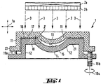
- the device shown in fig. 1 is designed for the manufacture of contact lenses from a liquid starting material which may be polymerized or crosslinked by UV radiation. It comprises a mold 1 and an energy source 2a, here a UV light source, as well as means 2b for directing the energy provided by the energy source 2a to the mold in the form of an essentially parallel beam.
- an energy source 2a here a UV light source
- means 2b for directing the energy provided by the energy source 2a to the mold in the form of an essentially parallel beam.
- the energy source 2a and means 2b can also be combined to form a single unit.
- the mold consists of two mold halves 11 and 12, each having a curved mold surface 13 and 14 which together define a mold cavity 15, which in turn determines the shape of the contact lens to be manufactured.
- the mold surface 13 of the upper mold half 11 in the drawing is convex and determines the rear and base surface of the contact lens with the connected edge area; this mold half is normally called the father mold half.
- the mold surface 14 of the other mold half which is correspondingly called the mother mold half, is concave and determines the front face of the contact lens to be manufactured, likewise with the connected edge area.
- the mold cavity 15 is not completely and tightly closed, but in the embodiment illustrated is open around its peripheral edge which defines the edge of the contact lens to be manufactured, and is linked to a relatively narrow annular gap 16.
- the annular gap 16 is limited or formed by a flat mold wall 17 and 18 on each of the father mold half 11 and the mother mold half 12.
- spacers for example in the form of several bolts 19a or 19b, are provided on the mother mold 12, and these interact with a collar or flange 20 of the father mold 11 and keep the two mold halves at such a distance apart that the said annular gap 16 results.
- spacers for example in the form of several bolts 19a or 19b
- the spacers may also be of adjustable or spring-action formation.
- the two mold halves 11, 12 can be moved towards one another during the crosslinking process to balance out leakage, by adjusting the spacers (indicated symbolically by the arrow 19c showing the direction of rotation) or against a spring action.
- the mold can be opened and closed in the usual manner, for example by means of a closure unit which is indicated here only by the arrow symbol 1a. Adjustment of the gap between the two mold halves 11, 12 to balance out leakage, may also be effected e.g. using this external closure unit.
- a mask 21 which is impermeable to the energy form employed, here this is UV light, (or a mask which at least has poor permeability compared with the permeability of the mold), and this mask extends right to the mold cavity 15, and with the exception of the same, screens all the other parts, hollow spaces or areas of the mold 1 that are in contact with or may come into contact with the liquid, uncrosslinked, possibly excess material, from the radiated energy. Partial areas of the lens edge are therefore formed not by a limitation of the material by mold walls, but by a spatial limitation of the radiation or other forms of energy triggering polymerization or crosslinking.
- the mask 21 may be preferably a chromium layer, that can be produced by processes known e.g. from photography or UV-lithography.
- the mask 21 does not necessary have to be fixed; it may also be, for example, removable or exchangeable.
- FIG. 2 shows the arrangement of the mold 1 in the transition region between the mold cavity 15 and the annular channel 16 as an enlarged detail.
- the cavity 15 has here, by way of example, a shape that corresponds to the typical rim geometry of a so-called soft contact lens CL.
- the cavity rim, and thus the lens rim is formed here by two wall faces 22 and 23 which are arranged at right angles to one another and are arranged on the male and on the female mold halves 11 and 12 respectively.
- the width and the height of those two wall faces, and of the rim areas of the contact lens defined by them, are indicated by X and Y respectively.
- the lens rim may in practice also be slightly rounded.
- the cylindrical wall face 23 of the female mold half 12 does not extend right up to the fiat wall face 22 and the wall face 17, lying seamlessly adjacent thereto, of the male mold half 11, but is lower by the amount ⁇ y, so that the annular gap 16 already mentioned , between the wall face 17 and the wall face 18 of the two mold halves 11 and 12, is formed or remains open.
- the mask 21 provided on the wall face 17 of the male mold half 11 in this example embodiment extends horizontally exactly up to the extension 23a of the wall face. 23 of the female mold half 12.
- the UV light in the form of a parallel beam 3 causing the crosslinking, is incident at right angles to the wall face 22 and 17 and parallel to the cylindrical wall face 23, the space located at right angles below the mask 21 is in shadow and only the material located inside the cavity 15, that is inside the imaginary wall extension 23a, is crosslinked, resulting in a clean and burr-free lens rim which does not require any subsequent mechanical processing.
- parallel energy radiation is used, therefore, disregarding the diffraction and scattering effects, which are usually negligible in practice, the contour of the mask 21 is transferred two-dimensionally parallel and (in this case) downwards into the rim area of the contact lens. Therefore, if the two mold halves 11 and 12 are separated from one another by the annular gap 16 of height ⁇ y, the rim is formed towards the outside of the area resulting from that displacement by means of the spatial restriction of the energy radiation.
- the invention in one respect, is directed a reusable mold for making a contact lens, comprising a first mold half having a first mold surface in contact with a silicone containing lens forming composition and a second mold half having a second mold surface in contact with the lens forming composition, wherein the first mold half and the second mold half are configured to receive each other such that a cavity is formed between the first mold surface and the second mold surface, wherein the cavity defines the shape of a contact lens to be molded, wherein the lens forming composition is polymerizable and/or crosslinkable by an actinic radiation, wherein at least one of the mold halves is made from chalcogenide glasses, Zinc Selenide or Zinc Sulfide.
- Lightstream TechnologyTM (Alcon) involving reusable molds and curing a lens-forming composition under a spatial limitation of actinic radiation.
- the impingement upon the material of the energy causing crosslinking is restricted spatially to the region of the mold cavity, so that substantially only the starting material located in the mold cavity, that is to say the region of the contact lens, is crosslinked. Any excess starting material present is not polymerised or crosslinked.
- partial areas of the contact lens edge are formed not by a mechanical limitation of the material by mold walls but by a spatial restriction of the impinging energy (usually UV or some other radiation) that triggers the polymerisation or crosslinking.
- the projected beam of radiation limits radiation (e.g., UV radiation) impinging on the pre-polymerization mixture of the lens-forming materials located in the path of the projected beam from the first molding surface to the second molding surface of the reusable mold.
- the resultant contact lens comprises an anterior surface defined by the first molding surface, an opposite posterior surface defined by the second molding surface, and a lens edge defined by the sectional profile of the projected radiation beam (i.e., a spatial limitation of radiation).
- Examples of reusable molds suitable for spatial limitation of radiation include without limitation those disclosed in U.S. Patent Nos. 6,627,124 , 6,800,225 , 7,384,590 , and 7,387,759 .
- the mold half facing away from the energy source it is in principle possible for the mold half facing away from the energy source to be produced from any material which withstands the crosslinkable material or components thereof.
- potential reflections and scattering of curing light are to be expected, depending on the type of energetic radiation (such as wavelength of curing light), and these may possibly lead to undesired effects such as producing flash on the edge because the reflections and scattering of curing light will polymerizing the lens forming material in the gap area between two molds.
- the invention is partly based on the discovery that a silicone hydrogel contact lens can be made using Lightstream TechnologyTM with mold system having at least one of the mold halves is made from chalcogenide glasses, Zinc Selenide or Zinc Sulfide enable to achieve a contact lens having a clean lens edge without flash because not only Chalcogenide glasses transmit NIR (near-IR), and MWIR (mid-wave IR), while Zinc Selenide and Zinc Sulfide have good light transmission from visible ⁇ 500-600 nm to ⁇ 15,000 nm but also Chalcogenide glasses, Zinc Selenide, Zinc Sulfide also have a UV transmission cut-off wavelength no less than 350 nm (defined as % transmission is no larger than 1%). It is believed that reduction of reflection and scattering of curing light by using a mold system having at least one of the mold halves is made from chalcogenide glasses, Zinc Selenide or Zinc Sulfide.
- Chalcogenide glasses, Zinc Selenide or Zinc Sulfide can be single point diamond turned (SPDT) to produce optical quality surfaces. Therefore, chalcogenide glasses, Zinc Selenide, Zinc Sulfide may be excellent fit as front curve mold materials.
- Zinc sulfide is also used as an infrared optical material, transmitting from visible wavelengths to just over 12 micrometers. It can be used planar as an optical window or shaped into a lens. It is made as microcrystalline sheets by the synthesis from hydrogen sulfide gas and zinc vapour, and this is sold as FLIR-grade (Forward Looking IR), where the zinc sulfide is in a milky-yellow, opaque form. This material when hot isostatically pressed (HIPed) to eliminate microscopic voids and defects which occur in the regular grade material and can be converted to a water-clear form known as Cleartran (trademark). Zinc sulfide is commercially available from Rohm & Haas / Morton Advanced Materials, Nivo Technology, Corning, Crystran and Fairfield Crystal Technology.
- Zinc Selenide is used as an infrared optical material with a wide transmission wavelength range (0.45 ⁇ m to 21.5 ⁇ m). Similar to zinc sulfide, Zinc Selenide is produced as microcrystalline sheets by synthesis from hydrogen selenide gas and zinc vapor. Zinc Selenide material is a chemically inert, non-hygroscopic and highly pure product that is very effective in many optical applications due to its extremely low bulk losses, high resistance to thermal shock and stability in virtually all environments, easily machined. To obtain superior transmittance, Zinc Selenide crystals are grown by Chemical Vapor Deposition process (CVD). Zinc Selenide CVD is polycrystalline material, demonstrates superior CO2 laser transmittance and is employed in the transmission optical components used in CO2 laser processing. Zinc Selenide is commercially available from Rohm & Haas / Morton Advanced Materials, Nivo Technology , Corning, Crystran and Fairfield Crystal Technology.
- Chalcogenide glasses are types of glass that contain a substantial amount of elements in the Chalcogenide element group (sulfur, selenium or tellurium). These types of glasses can provide good transmission between the 4.0 ⁇ m and 14.0 ⁇ m wavelengths. Chalcogenide glasses are commercially available from Schott.
- a lens-forming material refers to any material which can be polymerized and/or crosslinked by actinic radiation to form a contact lens.
- a preferred group of lens-forming materials are prepolymers which are water-soluble and/or meltable. It would be advantageous that a lens-forming material comprises primarily one or more prepolymers which are preferably in a substantially pure form (e.g., purified by ultrafiltration).
- prefunctionalised PVA (polyvinyl alcohol) polymer used as lens forming material, as illustrated in U.S. Patent Nos. 5,508,317 ; 8,030,369 and U.S. patent application publication no. 2006/0251696 .
- a more preferred group of lens -forming materials is silicone-containing hydrogel.
- silicone-containing hydrogel comprises at least one components selected from the group consisting of a silicone-containing vinylic monomer, a silicone-containing vinylic macromer, a silicone-containing prepolymer, a hydrophilic vinylic monomer, a hydrophobic vinylic monomer, a crosslinking agent, a free-radical initiator (photoinitiator or thermal initiator), a hydrophilic vinylic macromer/prepolymer, and combinations thereof, as well known to a person skilled in the art, as illustrated in U.S. Patent Nos. 5,760,100 and 8,480,227 .
- a still more preferred group of lens -forming materials is UV-absorbing silicone-containing hydrogel.
- UV-absorbing silicone-containing hydrogel lens forming mixture comprises at least one hydrophilic vinylic monomer, at least one siloxane-containing vinylic monomer, at least one polysiloxane crosslinker (with two or more ethylenically-unsaturated groups), at least one UV-absorbing vinylic monomer that absorbs ultraviolet light and optionally (but preferably) high-energy violet light from 381 nm to 440 nm, at least one tinting agent, and at least one germanium-based Norrish Type I photoinitiator capable of initiating a free-radical polymerization under irradiation with a light source including a light in the region of about 380 to about 550 nm, and the UV-absorbing silicone-containing hydrogel lens forming mixture is irradiated in the mold with a light in a region of from 380 to 550 nm and crosslinking the lens-forming materials to form the UV-absorbing silicone hydrogel contact lens, as illustrated in co-pending case, U.S.
- a UV-absorbing vinylic monomer used in the invention comprises a benzophenone-moiety, preferably a benzotriazole-moiety.
- a UV-absorbing vinylic monomer used in the invention is a benzotriazole-containing UV/HEVL absorber that absorbs both ultraviolet light and high-energy violet light (HEVL), for example, 2-(2'-hydroxy-5'-methacryloxyethylphenyl) benzotriazole (2-Propenoic acid, 2-methyl-, 2-[3-(2H-benzotriazol-2-yl)-4-hydroxyphenyl]ethyl ester, Norbloc).
- HUVL high-energy violet light
- germanium-based Norrish Type I photoinitiators can be used in the UV-absorbing silicone-containing hydrogel lens forming mixture, so long as they are capable of initiating a free-radical polymerization under irradiation with a light source including a light in the region of about 380 to about 550 nm.
- germanium-based Norrish Type I photoinitiators are acylgermanium compounds described in US 7,605,190 .
- light source can be any ones emitting light in the 380-550 nm range sufficient to activate germanium-based Norrish Type I photoinitiators.
- Blue-light sources are commercially available and include: the Palatray CU blue-light unit (available from Heraeus Kulzer, Inc., Irvine, Calif.), the Fusion F450 blue light system (available from TEAMCO, Richardson, Tex.), Dymax Blue Wave 200, LED light sources from Opsytec (385 nm, 395 nm, 405 nm, 435 nm, 445 nm, 460 nm), LED light sources from Hamamatsu (385 nm), and the GE 24" blue fluorescent lamp (available from General Electric Company, U.S.).
- a preferred blue-light source is the UV LED from Opsytec (those described above). The intensity of the light source is set to produce lenses of good quality given the light source and photoinitiator.
- the total intensity of the light source is preferably from about 10 to about 100 mW/cm2, preferably from about 20 to about 60 mW/cm2 in the 380 nm to 550 nm region is more preferred.
- the crosslinking may be effected in any time period of about 40 minutes or less, preferably in a very short time (e.g. in ⁇ about 120 seconds, preferably in ⁇ about 80 seconds, more preferably in ⁇ 50 about seconds, even more preferably in ⁇ about 30 seconds, and most preferably in 5 to 30 seconds).
- the invention in another respect, relates to a method for producing a contact lens, comprising: the steps of:
- IPDI isophorone diisocyanate
- the reactor is held for 4.5 h at about 40° C, forming HO-PDMS-IPDI-PDMS-IPDI-PDMS-OH.
- MEK is then removed under reduced pressure.
- the terminal hydroxyl-groups are capped with methacryloyloxyethyl groups in a third step by addition of 7.77 g of isocyanatoethylmethacrylate (IEM) and an additional 0.063 g of DBTDL, forming IEM-PDMS-IPDI-PDMS-IPDI-PDMS-IEM (i.e., CE-PDMS terminated with methacrylate groups).
- IEM isocyanatoethylmethacrylate
- 240.43 g of KF-6001 is added into a 1-L reactor equipped with stirring, thermometer, cryostat, dropping funnel, and nitrogen/vacuum inlet adapter, and then dried by application of high vacuum (2 ⁇ 10-2 mBar). Then, under an atmosphere of dry nitrogen, 320 g of distilled MEK is then added into the reactor and the mixture is stirred thoroughly. 0.235 g of DBTDL is added to the reactor. After the reactor is warmed to 45°C, 45.86 g of IPDI are added through an addition funnel over 10 minutes to the reactor under moderate stirring. The reaction is kept for 2 hours at 60°C.
- Lens formulation 2 is prepared by mixing components listed in Table 1 below followed by heating at 40°C for 20 min. Formulation 2 requires heating at 50°C for 20 min.
- Table 1 Lens formulation 2 CuP tint (%) 0.1 DMPC (%) 0.76 LPEG2000 (%) 0.61 Norbloc (%) 1 CE PDMS (%) 31.83 Tris acrylamide (%) 19.71 Ge-PI (%) 23.07 DMA (%) 23.24 L-PEG 2000: N-(carbonyl-methoxypolyethylene glycol-2000)-1,2-disteaoyl-sn-glycero-3-phosphoethanolamin, sodium salt; CE-PDMS: chain-extended polydimethylsiloxane crosslinker prepared in Example 2; DMA: N,N-dimethylacrylamide; TRIS-Am: N-[tris(trimethylsiloxy)-silylpropyl]acrylamide; DMPC: 1,2-Dimyristoyl-sn-glycero-3-phophopho
- PAA-coating solution A polyacrylic acid (PAA) coating solution is prepared by dissolving an amount of PAA (M.W.: 450kDa, from Lubrizol) in a given volume of 1-propanol (1-PrOH) to have a concentration of about 0.44% by weight and the pH is adjusted with formic acid to about 2.0.
- PAA polyacrylic acid
- IPC saline In-Package-Coating solution
- Poly(AAm-co-AA)(90/10) partial sodium salt ( ⁇ 90% solid content, poly(AAm-co-AA) 90/10, Mw 200,000) is purchased from Polysciences, Inc. and used as received.
- Polyamidonamine epichlorohydrin (PAE) (Kymene, an azetidinium content of 0.46 assayed with NMR) is purchased from Ashland as an aqueous solution and used as received.
- IPC saline is prepared by dissolving about 0.07% w/w of poly(AAm-co-AA)(90/10) and about 0.15% of PAE (an initial azetidinium millimolar equivalents of about 8.8 millimole) in phosphate-buffered saline (PBS) (about 0.044 w/w% NaH2PO4 ⁇ H2O, about 0.388 w/w/% Na2HPO4 ⁇ 2H2O, about 0.79 w/w% NaCl) and adjusting the pH to 7.2 ⁇ 7.4. Then the IPC saline is heat pre-treated for about 4 hours at about 70oC (heat pretreatment).
- PBS phosphate-buffered saline
- poly(AAm-co-AA) and PAE are partially crosslinked to each other (i.e., not consuming all azetidinium groups of PAE) to form a water-soluble and thermally-crosslinkable hydrophilic polymeric material containing azetidinium groups within the branched polymer network in the IPC saline.
- the IPC is cooled to room temperature then filtered using a 0.22micron PES membrane filter.
- Lenses are prepared by cast-molding from the lens formulation prepared above in two set of reusable mold.
- the first set for lens sample 2A uses quartz base curve mold half and N-B270 glass front curve mold half and the second set for lens sample 2B uses quartz base curve mold half and Zinc Selenide glass front curve mold half.
- Lens formulation 2 prepared in Example 2 are used for both lens samples 2A and 2B.
- Lens formulation in the molds are irradiated for 25 seconds using a 445 nm LED supplied by Opsytec.
- the measured total intensity from 200 to 800 nm is 54 mW/cm2 (total intensity).
- Cast-molded contact lenses are then extracted by dipping in the following series of baths: deionized (DI) water bath (about 56 seconds); 3 methyl ethyl ketone (MEK) baths (about 22, 78, 224 seconds respectively, (DI) water bath (about 56 seconds).
- DI deionized
- MEK 3 methyl ethyl ketone
- DI water bath
- Table 2 The lens properties and curing conditions are given in Table 2 below.
- Table 2 2A 2B Cure Lamp 445nm LED 445nm LED Total Intensity (mW/cm2) 54 54 Cure Time (s) 25 25 Base Curve /Front Curve Mold quartz /N-B270 glass quartz /ZnSe Lens Edge Quality Heavy flash, bad lens edge quality No flash, great lens edge quality
Description
- A great effort has been made to develop technologies for cast molding of hydrogel contact lenses with high precision, fidelity and reproducibility and at low cost. One of such manufacturing technologies is the so-called Lightstream Technology™ (Alcon) involving reusable molds and curing a lens-forming composition under a spatial limitation of actinic radiation (
U.S. Patent Nos. 5,508,317 ,5,583,163 ,5,789,464 ,5,849,810 , and8,163,206 ). The Lightstream Technology™ involves (1) a lens-forming composition, (2) reusable molds produced in high precision, and (3) curing under a spatial limitation of actinic radiation (e.g., UV/Visible light). Lenses produced according to the Lightstream Technology™ can have high consistency and high fidelity to the original lens design, because of use of reusable, high precision molds. In addition, contact lenses with high quality can be produced at relatively lower cost due to the short curing time and a high production yield. - Modern high-volume mass production process for medical devices like contact lenses utilizes re-usable molds in each production cycles. The conventional re-usable contact lens mold consists of a quartz convex base curve and a glass concave front curve. The base curve mold is composed of individually ground and polished quartz, while the front curve mold is composed of high precision press mold and polished glass. However, hydrogel contact lens production in curing under a spatial limitation of actinic radiation with Lightstream Technology™ may produce flash along lens edge due to lens forming material left in gap between base curve mold and front curve during curing under a spatial limitation of actinic radiation. Furthermore, when manufacturing UV absorbing contact lenses in the Lightstream technology, the lens edge quality issues (flash) become more severe than when manufacturing non-UV absorbing contact lenses.
- Therefore, there is a need for new reusable molds for front curve mold that can produce lens with clean cut lens edge (no flash).
- The invention, in one respect, relates to a reusable mold for making a contact lens, comprising a first mold half having a first mold surface in contact with a silicone containing lens forming composition and a second mold half having a second mold surface in contact with the lens forming composition, wherein the first mold half and the second mold half are configured to receive each other such that a cavity is formed between the first mold surface and the second mold surface, wherein the cavity defines the shape of a contact lens to be molded, wherein the lens forming composition is polymerizable and/or crosslinkable by an actinic radiation, wherein at least one of the mold halves is made from chalcogenide glasses, Zinc Selenide or Zinc Sulfide.
- The invention, in another respect, relates to a method for producing a contact lens, comprising: the steps of:
- (1) providing a contact lens mold, wherein the mold comprising a first mold half having a first mold and a second mold half having a second mold surface, wherein the first mold half and the second mold half are configured to receive each other such that a cavity is formed between the first mold surface and the second mold surface, wherein the cavity defines the shape of a contact lens to be molded, wherein at least one of the mold halves is made from chalcogenide glasses, Zinc Selenide or Zinc Sulfide, (2) introducing a lens-forming composition into the cavity formed by the first and second molding surfaces, material, wherein the lens-forming material is crosslinkable and/or polymerizable by actinic radiation; (3) crosslinking/polymerizing the lens-forming material in the mold to form a lens having a polymer matrix; (4) opening the mold and removing the formed contact lens from the mold, wherein the formed contact lens is characterized by having a clean lens edge without flash.
-
- Fig. 1
- shows a section through an exemplary embodiment of a casting mold according to the invention in the closed position;
- Fig. 2
- is a detail, indicated by II in
Fig. 1 , on a greatly enlarged scale. - Unless defined otherwise, all technical and scientific terms used herein have the same meaning as commonly understood by one of ordinary skill in the art to which this invention belongs. Generally, the nomenclature used herein and the laboratory procedures are well known and commonly employed in the art. Conventional methods are used for these procedures, such as those provided in the art and various general references. Where a term is provided in the singular, the inventors also contemplate the plural of that term. The nomenclature used herein and the laboratory procedures described below are those well-known and commonly employed in the art. As employed throughout the disclosure, the following terms, unless otherwise indicated, shall be understood to have the following meanings
"Quartz" refers to the second most abundant mineral in the Earth's continental crust, after feldspar. It is made up of a continuous framework of SiO4 silicon-oxygen tetrahedra, with each oxygen being shared between two tetrahedra, giving an overall formula SiO2. - "Flash" refers to excess material attached to a molded lens edge which must usually be mechanically removed. This is typically caused by curing the material between the two surfaces of a mold. For example, flash forms from lens forming material left in gap between base curve mold and front curve during curing under a spatial limitation of actinic radiation.
- "An optical quality surface" refers to a glass surface has a surface roughness less than 30 nm, preferably less than 20 nm, most preferably less than 10 nm.
- "About" as used herein means that a number referred to as "about" comprises the recited number plus or minus 1-10% of that recited number.
- "Optional" or "optionally" means that the subsequently described event or circumstance can or cannot occur, and that the description includes instances where the event or circumstance occurs and instances where it does not.
- An "ophthalmic lens" refers to a contact lens and/or an intraocular lens. A "contact lens" refers to a structure that can be placed on or within a wearer's eye. A contact lens can correct, improve, or alter a user's eyesight, but that need not be the case. A "silicone hydrogel contact lens" refers to a contact lens comprising a silicone hydrogel material.
- As used in this application, the term "hydrogel" or "hydrogel material" refers to a crosslinked polymeric material which is not water-soluble and can contains at least 10% by weight of water within its polymer matrix when fully hydrated.
- A "silicone hydrogel" refers to a hydrogel containing silicone. A silicone hydrogel typically is obtained by copolymerization of a polymerizable composition comprising at least one silicone-containing vinylic monomer or at least one silicone-containing vinylic macromer or at least one silicone-containing prepolymer having ethylenically unsaturated groups.
- A "vinylic monomer" refers to a compound that has one sole ethylenically-unsaturated group.
- The term "olefinically unsaturated group" or "ethylenically unsaturated group" is employed herein in a broad sense and is intended to encompass any groups containing at least one >C=C< group.
- A "UV-absorbing vinylic monomer" refers to a compound comprising an ethylenically-unsaturated group and a UV-absorbing moiety which can absorb or screen out UV radiation in the range from 200 nm to 400 nm as understood by a person skilled in the art.
- A "spatial limitation of actinic radiation" refers to an act or process in which energy radiation in the form of rays is directed by, for example, a mask or screen or combinations thereof, to impinge, in a spatially restricted manner, onto an area having a well-defined peripheral boundary. A spatial limitation of UV radiation is obtained by using a mask or screen having a radiation (e.g., UV and/or visible light) permeable region, a radiation (e.g., UV and/or visible light) impermeable region surrounding the radiation-permeable region, and a projection contour which is the boundary between the radiation-impermeable and radiation-permeable regions, as schematically illustrated in the drawings of
U.S. Patent Nos. 6,800,225 (Figs. 1-11 ), and6,627,124 (Figs. 1-9 ),7,384,590 (Figs. 1-6 ), and7,387,759 (Figs. 1-6 ). The mask or screen allows to spatially projects a beam of radiation (e.g., UV radiation and/or visible radiation) having a cross-sectional profile defined by the projection contour of the mask or screen. The projected beam of radiation (e.g., UV radiation and/or visible radiation) limits radiation impinging on a lens formulation located in the path of the projected beam from the first molding surface to the second molding surface of a mold. The resultant contact lens comprises an anterior surface defined by the first molding surface, an opposite posterior surface defined by the second molding surface, and a lens edge defined by the sectional profile of the projected UV and/or visible beam (i.e., a spatial limitation of radiation). The radiation used for the crosslinking is radiation energy, especially UV radiation (and/or visible radiation), gamma radiation, electron radiation or thermal radiation, the radiation energy preferably being in the form of a substantially parallel beam in order on the one hand to achieve good restriction and on the other hand efficient use of the energy. - A "lens-forming material" refers to a material which can be polymerized and/or crosslinked by actinic radiation to form a contact lens.
- "Actinic radiation" refers to radiation of a suitable form of energy. Examples of actinic radiation includes without limitation light radiation (e.g., UV radiation), gamma radiation, electron radiation, X-ray irradiation, microwave irradiation, thermal radiation and the like.
- "UVA" refers to radiation occurring at wavelengths between 316 and 380 nanometers; "UVB" refers to radiation occurring between 280 and 315 nanometers; "Violet" refers to radiation occurring at wavelengths between 381 and 440 nanometers.
- "UVA transmittance" (or "UVA %T"), "UVB transmittance" or "UVB %T", and "average violet-transmittance" or "Violet %T" are calculated by the following formula:


- in which Luminescence %T is defined according to ISO 18369-3 (section 4.6.1.2)
"UV-absorbing silicone hydrogel contact lenses" refers silicone hydrogel contact lenses which have an UVB transmittance of about 10% or less between 280 and 315 nanometers, an UVA transmittance of about 30% or less between 316 and 380 nanometers, optionally (but preferably) an average violet transmittance of about 70% or less between 381 nm and 440 nm. UV-absorbing silicone hydrogel contact lenses protect eyes to some extent from damages caused by UV radiation and potentially by high energy violet light (HEVL). - Further aspects and advantages of the process according to the invention and of the device according to the invention will be seen from the description that follows, in conjunction with the drawings.
- The device shown in
fig. 1 is designed for the manufacture of contact lenses from a liquid starting material which may be polymerized or crosslinked by UV radiation. It comprises amold 1 and an energy source 2a, here a UV light source, as well as means 2b for directing the energy provided by the energy source 2a to the mold in the form of an essentially parallel beam. Of course, the energy source 2a and means 2b can also be combined to form a single unit. - The mold consists of two
mold halves curved mold surface mold cavity 15, which in turn determines the shape of the contact lens to be manufactured. Themold surface 13 of theupper mold half 11 in the drawing is convex and determines the rear and base surface of the contact lens with the connected edge area; this mold half is normally called the father mold half. Conversely, themold surface 14 of the other mold half, which is correspondingly called the mother mold half, is concave and determines the front face of the contact lens to be manufactured, likewise with the connected edge area. - The
mold cavity 15 is not completely and tightly closed, but in the embodiment illustrated is open around its peripheral edge which defines the edge of the contact lens to be manufactured, and is linked to a relatively narrowannular gap 16. Theannular gap 16 is limited or formed by aflat mold wall father mold half 11 and themother mold half 12. In order to prevent complete closure of the mold, spacers, for example in the form ofseveral bolts mother mold 12, and these interact with a collar orflange 20 of thefather mold 11 and keep the two mold halves at such a distance apart that the saidannular gap 16 results. As is indicated symbolically infig. 1 by the right-hand spacer bolt 19b with a thread, the spacers may also be of adjustable or spring-action formation. In this way, the twomold halves arrow 19c showing the direction of rotation) or against a spring action. Of course, the mold can be opened and closed in the usual manner, for example by means of a closure unit which is indicated here only by the arrow symbol 1a. Adjustment of the gap between the twomold halves - It is also conceivable that, instead of the continuous
annular gap 16 and thespacers - On the
mold wall 17 in the area of theannular gap 16, there is amask 21 which is impermeable to the energy form employed, here this is UV light, (or a mask which at least has poor permeability compared with the permeability of the mold), and this mask extends right to themold cavity 15, and with the exception of the same, screens all the other parts, hollow spaces or areas of themold 1 that are in contact with or may come into contact with the liquid, uncrosslinked, possibly excess material, from the radiated energy. Partial areas of the lens edge are therefore formed not by a limitation of the material by mold walls, but by a spatial limitation of the radiation or other forms of energy triggering polymerization or crosslinking. - In the case of UV light, the
mask 21 may be preferably a chromium layer, that can be produced by processes known e.g. from photography or UV-lithography. Themask 21 does not necessary have to be fixed; it may also be, for example, removable or exchangeable. -
FIG. 2 shows the arrangement of themold 1 in the transition region between themold cavity 15 and theannular channel 16 as an enlarged detail. Thecavity 15 has here, by way of example, a shape that corresponds to the typical rim geometry of a so-called soft contact lens CL. The cavity rim, and thus the lens rim, is formed here by two wall faces 22 and 23 which are arranged at right angles to one another and are arranged on the male and on the female mold halves 11 and 12 respectively. The width and the height of those two wall faces, and of the rim areas of the contact lens defined by them, are indicated by X and Y respectively. Obviously, the lens rim may in practice also be slightly rounded. - As can be seen clearly, the cylindrical wall face 23 of the
female mold half 12 does not extend right up to the fiat wall face 22 and thewall face 17, lying seamlessly adjacent thereto, of themale mold half 11, but is lower by the amount Δy, so that theannular gap 16 already mentioned , between thewall face 17 and thewall face 18 of the twomold halves
Themask 21 provided on thewall face 17 of themale mold half 11 in this example embodiment extends horizontally exactly up to the extension 23a of the wall face. 23 of thefemale mold half 12. If the UV light, in the form of aparallel beam 3 causing the crosslinking, is incident at right angles to thewall face 22 and 17 and parallel to the cylindrical wall face 23, the space located at right angles below themask 21 is in shadow and only the material located inside thecavity 15, that is inside the imaginary wall extension 23a, is crosslinked, resulting in a clean and burr-free lens rim which does not require any subsequent mechanical processing. If parallel energy radiation is used, therefore, disregarding the diffraction and scattering effects, which are usually negligible in practice, the contour of themask 21 is transferred two-dimensionally parallel and (in this case) downwards into the rim area of the contact lens. Therefore, if the twomold halves annular gap 16 of height Δy, the rim is formed towards the outside of the area resulting from that displacement by means of the spatial restriction of the energy radiation. - In general, the invention, in one respect, is directed a reusable mold for making a contact lens, comprising a first mold half having a first mold surface in contact with a silicone containing lens forming composition and a second mold half having a second mold surface in contact with the lens forming composition, wherein the first mold half and the second mold half are configured to receive each other such that a cavity is formed between the first mold surface and the second mold surface, wherein the cavity defines the shape of a contact lens to be molded, wherein the lens forming composition is polymerizable and/or crosslinkable by an actinic radiation, wherein at least one of the mold halves is made from chalcogenide glasses, Zinc Selenide or Zinc Sulfide.
- Lightstream Technology™ (Alcon) involving reusable molds and curing a lens-forming composition under a spatial limitation of actinic radiation. According to the Lightstream Technology™, the impingement upon the material of the energy causing crosslinking is restricted spatially to the region of the mold cavity, so that substantially only the starting material located in the mold cavity, that is to say the region of the contact lens, is crosslinked. Any excess starting material present is not polymerised or crosslinked. In that arrangement, partial areas of the contact lens edge are formed not by a mechanical limitation of the material by mold walls but by a spatial restriction of the impinging energy (usually UV or some other radiation) that triggers the polymerisation or crosslinking. As a result of those two measures, contact between the two mold halves can in a preferred arrangement be avoided, so that they are not deformed and can accordingly be used again.
- A reusable mold suitable for spatial limitation of radiation is used in the invention, the projected beam of radiation limits radiation (e.g., UV radiation) impinging on the pre-polymerization mixture of the lens-forming materials located in the path of the projected beam from the first molding surface to the second molding surface of the reusable mold. The resultant contact lens comprises an anterior surface defined by the first molding surface, an opposite posterior surface defined by the second molding surface, and a lens edge defined by the sectional profile of the projected radiation beam (i.e., a spatial limitation of radiation). Examples of reusable molds suitable for spatial limitation of radiation include without limitation those disclosed in
U.S. Patent Nos. 6,627,124 ,6,800,225 ,7,384,590 , and7,387,759 . - According to the present invention, applying energy on one side, it is in principle possible for the mold half facing away from the energy source to be produced from any material which withstands the crosslinkable material or components thereof. However, potential reflections and scattering of curing light are to be expected, depending on the type of energetic radiation (such as wavelength of curing light), and these may possibly lead to undesired effects such as producing flash on the edge because the reflections and scattering of curing light will polymerizing the lens forming material in the gap area between two molds.
- The invention is partly based on the discovery that a silicone hydrogel contact lens can be made using Lightstream Technology™ with mold system having at least one of the mold halves is made from chalcogenide glasses, Zinc Selenide or Zinc Sulfide enable to achieve a contact lens having a clean lens edge without flash because not only Chalcogenide glasses transmit NIR (near-IR), and MWIR (mid-wave IR), while Zinc Selenide and Zinc Sulfide have good light transmission from visible ∼ 500-600 nm to ∼15,000 nm but also Chalcogenide glasses, Zinc Selenide, Zinc Sulfide also have a UV transmission cut-off wavelength no less than 350 nm (defined as % transmission is no larger than 1%). It is believed that reduction of reflection and scattering of curing light by using a mold system having at least one of the mold halves is made from chalcogenide glasses, Zinc Selenide or Zinc Sulfide.
- Chalcogenide glasses, Zinc Selenide or Zinc Sulfide can be single point diamond turned (SPDT) to produce optical quality surfaces. Therefore, chalcogenide glasses, Zinc Selenide, Zinc Sulfide may be excellent fit as front curve mold materials.
- Zinc sulfide is also used as an infrared optical material, transmitting from visible wavelengths to just over 12 micrometers. It can be used planar as an optical window or shaped into a lens. It is made as microcrystalline sheets by the synthesis from hydrogen sulfide gas and zinc vapour, and this is sold as FLIR-grade (Forward Looking IR), where the zinc sulfide is in a milky-yellow, opaque form. This material when hot isostatically pressed (HIPed) to eliminate microscopic voids and defects which occur in the regular grade material and can be converted to a water-clear form known as Cleartran (trademark). Zinc sulfide is commercially available from Rohm & Haas / Morton Advanced Materials, Nivo Technology, Corning, Crystran and Fairfield Crystal Technology.
- Zinc Selenide is used as an infrared optical material with a wide transmission wavelength range (0.45 µm to 21.5 µm). Similar to zinc sulfide, Zinc Selenide is produced as microcrystalline sheets by synthesis from hydrogen selenide gas and zinc vapor. Zinc Selenide material is a chemically inert, non-hygroscopic and highly pure product that is very effective in many optical applications due to its extremely low bulk losses, high resistance to thermal shock and stability in virtually all environments, easily machined. To obtain superior transmittance, Zinc Selenide crystals are grown by Chemical Vapor Deposition process (CVD). Zinc Selenide CVD is polycrystalline material, demonstrates superior CO2 laser transmittance and is employed in the transmission optical components used in CO2 laser processing. Zinc Selenide is commercially available from Rohm & Haas / Morton Advanced Materials, Nivo Technology , Corning, Crystran and Fairfield Crystal Technology.
- Chalcogenide glasses are types of glass that contain a substantial amount of elements in the Chalcogenide element group (sulfur, selenium or tellurium). These types of glasses can provide good transmission between the 4.0µm and 14.0µm wavelengths. Chalcogenide glasses are commercially available from Schott.
- According to the present invention, a lens-forming material refers to any material which can be polymerized and/or crosslinked by actinic radiation to form a contact lens. A preferred group of lens-forming materials are prepolymers which are water-soluble and/or meltable. It would be advantageous that a lens-forming material comprises primarily one or more prepolymers which are preferably in a substantially pure form (e.g., purified by ultrafiltration). For example, prefunctionalised PVA (polyvinyl alcohol) polymer used as lens forming material, as illustrated in
U.S. Patent Nos. 5,508,317 ;8,030,369 andU.S. patent application publication no. 2006/0251696 . A more preferred group of lens -forming materials is silicone-containing hydrogel. Generally silicone-containing hydrogel comprises at least one components selected from the group consisting of a silicone-containing vinylic monomer, a silicone-containing vinylic macromer, a silicone-containing prepolymer, a hydrophilic vinylic monomer, a hydrophobic vinylic monomer, a crosslinking agent, a free-radical initiator (photoinitiator or thermal initiator), a hydrophilic vinylic macromer/prepolymer, and combinations thereof, as well known to a person skilled in the art, as illustrated inU.S. Patent Nos. 5,760,100 and8,480,227 . A still more preferred group of lens -forming materials is UV-absorbing silicone-containing hydrogel. Generally UV-absorbing silicone-containing hydrogel lens forming mixture comprises at least one hydrophilic vinylic monomer, at least one siloxane-containing vinylic monomer, at least one polysiloxane crosslinker (with two or more ethylenically-unsaturated groups), at least one UV-absorbing vinylic monomer that absorbs ultraviolet light and optionally (but preferably) high-energy violet light from 381 nm to 440 nm, at least one tinting agent, and at least one germanium-based Norrish Type I photoinitiator capable of initiating a free-radical polymerization under irradiation with a light source including a light in the region of about 380 to about 550 nm, and the UV-absorbing silicone-containing hydrogel lens forming mixture is irradiated in the mold with a light in a region of from 380 to 550 nm and crosslinking the lens-forming materials to form the UV-absorbing silicone hydrogel contact lens, as illustrated in co-pending case,U.S. Patent Application No. 61/884181 US 7,605,190 . For curing the UV-absorbing silicone-containing hydrogel lens forming mixture, light source can be any ones emitting light in the 380-550 nm range sufficient to activate germanium-based Norrish Type I photoinitiators. Blue-light sources are commercially available and include: the Palatray CU blue-light unit (available from Heraeus Kulzer, Inc., Irvine, Calif.), the Fusion F450 blue light system (available from TEAMCO, Richardson, Tex.), Dymax Blue Wave 200, LED light sources from Opsytec (385 nm, 395 nm, 405 nm, 435 nm, 445 nm, 460 nm), LED light sources from Hamamatsu (385 nm), and the GE 24" blue fluorescent lamp (available from General Electric Company, U.S.). A preferred blue-light source is the UV LED from Opsytec (those described above). The intensity of the light source is set to produce lenses of good quality given the light source and photoinitiator. The total intensity of the light source is preferably from about 10 to about 100 mW/cm2, preferably from about 20 to about 60 mW/cm2 in the 380 nm to 550 nm region is more preferred. The crosslinking may be effected in any time period of about 40 minutes or less, preferably in a very short time (e.g. in ≤ about 120 seconds, preferably in ≤ about 80 seconds, more preferably in ≤ 50 about seconds, even more preferably in ≤ about 30 seconds, and most preferably in 5 to 30 seconds). - The invention, in another respect, relates to a method for producing a contact lens, comprising: the steps of:
- (1) providing a contact lens mold, wherein the mold comprising a first mold half having a first mold and a second mold half having a second mold surface, wherein the first mold half and the second mold half are configured to receive each other such that a cavity is formed between the first mold surface and the second mold surface, wherein the cavity defines the shape of a contact lens to be molded, wherein at least one of the mold halves is made from chalcogenide glasses, Zinc Selenide glass or Zinc Sulfide glass,
- (2) introducing a lens-forming composition into the cavity formed by the first and second molding surfaces, material, wherein the lens-forming material is crosslinkable and/or polymerizable by actinic radiation;
- (3) crosslinking/polymerizing the lens-forming material in the mold to form a lens having a polymer matrix;
- (4) opening the mold and removing the formed contact lens from the mold,
- The previous disclosure will enable one having ordinary skill in the art to practice the invention. Various modifications, variations, and combinations can be made to the various embodiment described herein. In order to better enable the reader to understand specific embodiments and the advantages thereof, reference to the following examples is suggested. It is intended that the specification and examples be considered as exemplary.
- In the first step, α,ω-bis(2-hydroxyethoxypropyl)-polydimethylsiloxane (Mn = 2000, Shin-Etsu, KF-6001a) is capped with isophorone diisocyanate (IPDI) by reacting 49.85 g of α,ω-bis(2-hydroxyethoxypropyl)-polydimethylsiloxane with 11.1 g IPDI in 150 g of dry methyl ethyl ketone (MEK) in the presence of 0.063g of dibutyltindilaurate (DBTDL). The reaction is kept for 4.5 h at 40° C, forming IPDI-PDMS-IPDI. In the second step, a mixture of 164.8 g of α,ω-bis(2-hydroxyethoxypropyl)-polydimethylsiloxane (Mn = 3000, Shin-Etsu, KF-6002) and 50 g of dry MEK are added dropwise to the IPDI-PDMS-IPDI solution to which has been added an additional 0.063 g of DBTDL. The reactor is held for 4.5 h at about 40° C, forming HO-PDMS-IPDI-PDMS-IPDI-PDMS-OH. MEK is then removed under reduced pressure. In the third step, the terminal hydroxyl-groups are capped with methacryloyloxyethyl groups in a third step by addition of 7.77 g of isocyanatoethylmethacrylate (IEM) and an additional 0.063 g of DBTDL, forming IEM-PDMS-IPDI-PDMS-IPDI-PDMS-IEM (i.e., CE-PDMS terminated with methacrylate groups).
- 240.43 g of KF-6001 is added into a 1-L reactor equipped with stirring, thermometer, cryostat, dropping funnel, and nitrogen/vacuum inlet adapter, and then dried by application of high vacuum (2×10⁻² mBar). Then, under an atmosphere of dry nitrogen, 320 g of distilled MEK is then added into the reactor and the mixture is stirred thoroughly. 0.235 g of DBTDL is added to the reactor. After the reactor is warmed to 45°C, 45.86 g of IPDI are added through an addition funnel over 10 minutes to the reactor under moderate stirring. The reaction is kept for 2 hours at 60°C. 630 g of KF-6002 dissolved in 452 g of distilled MEK are then added and stirred until a homogeneous solution is formed. About 0.235 g of DBTDL is added, and the reactor is held at about 55°C overnight under a blanket of dry nitrogen. The next day, MEK is removed by flash distillation. The reactor is cooled and 22.7 g of IEM are then charged to the reactor followed by about 0.235 g of DBTDL. After about 3 hours, an additional 3.3 g of IEM are added and the reaction is allowed to proceed overnight. The following day, the reaction mixture is cooled to about 18°C to obtain CE-PDMS macromer with terminal methacrylate groups.
- Lens formulation 2 is prepared by mixing components listed in Table 1 below followed by heating at 40°C for 20 min. Formulation 2 requires heating at 50°C for 20 min.
Table 1 Lens formulation 2 CuP tint (%) 0.1 DMPC (%) 0.76 LPEG2000 (%) 0.61 Norbloc (%) 1 CE PDMS (%) 31.83 Tris acrylamide (%) 19.71 Ge-PI (%) 0.6 1-propanol (%) 23.07 DMA (%) 23.24 L-PEG 2000: N-(carbonyl-methoxypolyethylene glycol-2000)-1,2-disteaoyl-sn-glycero-3-phosphoethanolamin, sodium salt;
CE-PDMS: chain-extended polydimethylsiloxane crosslinker prepared in Example 2;
DMA: N,N-dimethylacrylamide;
TRIS-Am: N-[tris(trimethylsiloxy)-silylpropyl]acrylamide;
DMPC: 1,2-Dimyristoyl-sn-glycero-3-phophocholine
CuP tint: 5% copper phthalocyanine blue pigment dispersion in
TRIS acrylamide tris(trimethylsiloxy)silylpropylmethacrylate, - PAA-coating solution. A polyacrylic acid (PAA) coating solution is prepared by dissolving an amount of PAA (M.W.: 450kDa, from Lubrizol) in a given volume of 1-propanol (1-PrOH) to have a concentration of about 0.44% by weight and the pH is adjusted with formic acid to about 2.0.
- Preparation of In-Package-Coating solution (IPC saline). Poly(AAm-co-AA)(90/10) partial sodium salt (∼90% solid content, poly(AAm-co-AA) 90/10, Mw 200,000) is purchased from Polysciences, Inc. and used as received. Polyamidonamine epichlorohydrin (PAE) (Kymene, an azetidinium content of 0.46 assayed with NMR) is purchased from Ashland as an aqueous solution and used as received. IPC saline is prepared by dissolving about 0.07% w/w of poly(AAm-co-AA)(90/10) and about 0.15% of PAE (an initial azetidinium millimolar equivalents of about 8.8 millimole) in phosphate-buffered saline (PBS) (about 0.044 w/w% NaH2PO4·H2O, about 0.388 w/w/% Na2HPO4·2H2O, about 0.79 w/w% NaCl) and adjusting the pH to 7.2∼7.4. Then the IPC saline is heat pre-treated for about 4 hours at about 70oC (heat pretreatment). During this heat pretreatment, poly(AAm-co-AA) and PAE are partially crosslinked to each other (i.e., not consuming all azetidinium groups of PAE) to form a water-soluble and thermally-crosslinkable hydrophilic polymeric material containing azetidinium groups within the branched polymer network in the IPC saline. After the heat pre-treatment, the IPC is cooled to room temperature then filtered using a 0.22micron PES membrane filter.
- Lens Fabrication using Formulation 2.
- Lenses are prepared by cast-molding from the lens formulation prepared above in two set of reusable mold. The first set for lens sample 2A uses quartz base curve mold half and N-B270 glass front curve mold half and the second set for lens sample 2B uses quartz base curve mold half and Zinc Selenide glass front curve mold half. Lens formulation 2 prepared in Example 2 are used for both lens samples 2A and 2B. Lens formulation in the molds are irradiated for 25 seconds using a 445 nm LED supplied by Opsytec. The measured total intensity from 200 to 800 nm is 54 mW/cm2 (total intensity). Cast-molded contact lenses are then extracted by dipping in the following series of baths: deionized (DI) water bath (about 56 seconds); 3 methyl ethyl ketone (MEK) baths (about 22, 78, 224 seconds respectively, (DI) water bath (about 56 seconds). After lens extraction, the lenses are in contact for 44 seconds with the PAA-coating solution prepared above to form a PAA coating on each lens, then equilibrated into water, and then placed into polypropylene shells containing 0.65 mL of IPC saline prepared above, and autoclaved for 45 minutes at 121°C.
- The lens properties and curing conditions are given in Table 2 below.
Table 2 2A 2B Cure Lamp 445nm LED 445nm LED Total Intensity (mW/cm2) 54 54 Cure Time (s) 25 25 Base Curve /Front Curve Mold quartz /N-B270 glass quartz /ZnSe Lens Edge Quality Heavy flash, bad lens edge quality No flash, great lens edge quality
Claims (15)
- A mold (1) for making a contact lens, comprising a first mold half (11) having a first mold surface (13) in contact with a silicone containing lens forming composition and a second mold half (12) having a second mold surface (14) in contact with the lens forming composition, wherein the first mold half (11) and the second mold half (12) are configured to receive each other such that a cavity (15) is formed between the first mold surface and the second mold surface, wherein the cavity (15) defines the shape of a contact lens to be molded, wherein the lens forming composition is polymerizable and/or crosslinkable by actinic radiation, characterized in that at least one of the mold halves (11, 12) is made from chalcogenide glasses, Zinc Selenide or Zinc Sulfide.
- The mold for making a contact lens according to claim 1, wherein the mold hatf is made from Zinc Selenide.
- The mold for making a contact lens according to claim 1, wherein the mold half is made from Zinc Sulfide.
- The mold for making a contact lens according to anyone of preceding claims, wherein the mold half has a UV transmission cut-off wavelength no less than 350 nm.
- The mold for making a contact lens according to anyone of preceding claims, wherein the mold half is single point diamond turned to produce optical quality surfaces.
- A method for producing a contact lens, comprising: the steps of:(1) providing a contact lens mold, (1) wherein the mold comprises a first mold half (11) having a first mold surface (13) and a second mold half (12) having a second mold surface (14) wherein the first mold half and the second mold half are configured to receive each other such that a cavity (15) is formed between the first mold surface (13) and the second mold surface, (14) wherein the cavity (15) defines the shape of a contact lens to be molded, wherein at least one of the mold halves is made from chalcogenide glasses, Zinc Selenide or Zinc Sulfide,(2) introducing a lens-forming composition into the cavity (15) formed by the first and second molding surfaces (13, 14) wherein the lens-forming material is crosslinkable and/or polymerizable by actinic radiation;(3) crosslinking/polymerizing the lens-forming material in the mold to form a lens having a polymer matrix;(4) opening the mold (1) and removing the formed contact lens from the mold, wherein the formed contact lens has a clean lens edge without flash.
- The method for producing a contact lens according to claim 6, wherein in step (1) the mold halve is made from Zinc Selenide.
- The method for producing a contact lens according to claim 6, wherein the mold half is made from Zinc Sulfide.
- The method for producing a contact lens according to anyone of claims 6 to 8, wherein the mold half has a UV transmission cut-off wavelength no less than 350 nm.
- The method for producing a contact lens according to anyone of claims 6 to 9,
wherein the mold half is single point diamond turned to produce optical quality surfaces. - The method for producing a contact lens according to anyone of claims 6 to 10,
wherein the lens-forming composition comprises at least one components selected from the group consisting of a silicone-containing vinylic monomer, a silicone-containing vinylic macromer, a silicone-containing prepolymer, a hydrophilic vinylic monomer, a hydrophobic vinylic monomer, a crosslinking agent, a free-radical initiator (photoinitiator or thermal initiator), a hydrophilic vinylic macromer/prepolymer, and combinations thereof. - The method for producing a contact lens according to anyone of claims 6 to 11, wherein the lens-forming composition further comprises at least one UV-absorbing vinylic monomer that absorbs ultraviolet light.
- The method for producing a contact lens according to anyone of claims 6 to 12,
wherein the lens-forming composition further comprises at least one germanium-based Norrish Type I photoinitiator. - The method for producing a contact lens according to anyone of claims 6 to 13,
wherein the lens-forming composition is crosslinked and/or polymerized by UV LED in a region from 380 nm to 550 nm. - The method for producing a contact lens according to anyone of claims 6 to 14,
wherein the lens-forming composition is crosslinked and/or polymerized by UV LED with a total intensity from about 10 to about 100 mW/cm2 in the region from 380 nm to 550 nm.
Applications Claiming Priority (2)
| Application Number | Priority Date | Filing Date | Title |
|---|---|---|---|
| US201462092891P | 2014-12-17 | 2014-12-17 | |
| PCT/US2015/065994 WO2016100448A1 (en) | 2014-12-17 | 2015-12-16 | Reusable lens molds and methods of use thereof |
Publications (2)
| Publication Number | Publication Date |
|---|---|
| EP3233450A1 EP3233450A1 (en) | 2017-10-25 |
| EP3233450B1 true EP3233450B1 (en) | 2019-01-30 |
Family
ID=55080187
Family Applications (1)
| Application Number | Title | Priority Date | Filing Date |
|---|---|---|---|
| EP15823069.8A Active EP3233450B1 (en) | 2014-12-17 | 2015-12-16 | Reusable lens molds and methods of use thereof |
Country Status (7)
| Country | Link |
|---|---|
| US (1) | US9981435B2 (en) |
| EP (1) | EP3233450B1 (en) |
| CN (1) | CN107000344B (en) |
| HU (1) | HUE044106T2 (en) |
| MY (1) | MY181957A (en) |
| SG (1) | SG11201703341XA (en) |
| WO (1) | WO2016100448A1 (en) |
Families Citing this family (2)
| Publication number | Priority date | Publication date | Assignee | Title |
|---|---|---|---|---|
| KR102527262B1 (en) * | 2017-10-17 | 2023-04-28 | 매직 립, 인코포레이티드 | Methods and Apparatuses for Casting Polymer Products |
| CN112522526A (en) * | 2020-11-25 | 2021-03-19 | 云南驰宏国际锗业有限公司 | Method for recovering germanium in wiping auxiliary material in germanium lens processing process |
Family Cites Families (31)
| Publication number | Priority date | Publication date | Assignee | Title |
|---|---|---|---|---|
| US3869323A (en) | 1973-12-28 | 1975-03-04 | Ibm | Method of polishing zinc selenide |
| US4944900A (en) | 1983-03-16 | 1990-07-31 | Raytheon Company | Polycrystalline zinc sulfide and zinc selenide articles having improved optical quality |
| JPS61106211A (en) | 1984-10-30 | 1986-05-24 | Hoya Corp | Mold for manufacturing hydrophilic plastic lens and manufacture of the same by employing the mold |
| US5071460A (en) | 1988-03-04 | 1991-12-10 | Nippon Telegraph And Telephone Corporation | Process for the preparation of fluoride glass and process for the preparation of optical fiber preform using the fluoride glass |
| US4898777A (en) | 1989-01-24 | 1990-02-06 | Infrared Fiber Systems | High-strength fluoride glass fibers and process of making |
| US5077239A (en) | 1990-01-16 | 1991-12-31 | Westinghouse Electric Corp. | Chalcogenide glass, associated method and apparatus |
| JPH0662318B2 (en) | 1990-05-23 | 1994-08-17 | セントラル硝子株式会社 | Surface treatment method for fluoride glass |
| JP2913808B2 (en) | 1990-09-25 | 1999-06-28 | 住友電気工業株式会社 | Manufacturing method of ZnSe blue light emitting device |
| US6800225B1 (en) | 1994-07-14 | 2004-10-05 | Novartis Ag | Process and device for the manufacture of mouldings and mouldings manufactured in accordance with that process |
| TW272976B (en) | 1993-08-06 | 1996-03-21 | Ciba Geigy Ag | |
| US5760100B1 (en) | 1994-09-06 | 2000-11-14 | Ciba Vision Corp | Extended wear ophthalmic lens |
| US5629246A (en) | 1995-09-27 | 1997-05-13 | Micron Technology, Inc. | Method for forming fluorine-doped glass having low concentrations of free fluorine |
| EP0835848A3 (en) | 1996-08-21 | 1998-06-10 | Nikon Corporation | Fluorine-containing silica glass, its method of manufacture and a projection exposure apparatus comprising the glass |
| TW429327B (en) * | 1997-10-21 | 2001-04-11 | Novartis Ag | Single mould alignment |
| JP2000326347A (en) | 1999-05-21 | 2000-11-28 | Menicon Co Ltd | Mold for lens for eye and manufacture of lens for eye using the same |
| JP2002114531A (en) | 2000-08-04 | 2002-04-16 | Sumitomo Electric Ind Ltd | Fluorine added glass |
| US7384590B2 (en) | 2002-12-17 | 2008-06-10 | Novartis Ag | System and method for curing polymeric moldings |
| US7387759B2 (en) | 2002-12-17 | 2008-06-17 | Novartis Ag | System and method for curing polymeric moldings having a masking collar |
| JP3857703B2 (en) * | 2004-08-19 | 2006-12-13 | 株式会社日本製鋼所 | Manufacturing method and manufacturing apparatus of molded body |
| US8030369B2 (en) | 2004-10-13 | 2011-10-04 | Novartis Ag | Contact lenses with improved wearing comfort |
| US7116888B1 (en) | 2005-04-13 | 2006-10-03 | Corning, Incorporated | Chalcogenide glass for low viscosity extrusion and injection molding |
| US9804295B2 (en) | 2005-05-05 | 2017-10-31 | Novartis Ag | Ophthalmic devices for sustained delivery of active compounds |
| EP1905415B1 (en) | 2006-09-27 | 2009-07-01 | Ivoclar Vivadent AG | Polymerisable compositions comprising acyl-germanium as initiators |
| JP2009063941A (en) * | 2007-09-10 | 2009-03-26 | Sumitomo Electric Ind Ltd | Far-infrared camera lens, lens unit, and imaging apparatus |
| US20100022378A1 (en) | 2008-07-25 | 2010-01-28 | Nguyen Vinh Q | Manufacturing process for chalcogenide glasses |
| WO2010071691A1 (en) | 2008-12-18 | 2010-06-24 | Novartis Ag | Method for making silicone hydrogel contact lenses |
| JP5514058B2 (en) | 2009-09-18 | 2014-06-04 | ローム・アンド・ハース・エレクトロニック・マテリアルズ,エル.エル.シー. | Method for manufacturing durable article |
| RU2540655C2 (en) | 2010-07-30 | 2015-02-10 | Новартис Аг | Silicone hydrogel lenses with water-rich surfaces |
| US9568645B2 (en) | 2013-09-30 | 2017-02-14 | Novartis Ag | Silicone hydrogel lenses with relatively-long thermal stability |
| WO2015048035A1 (en) | 2013-09-30 | 2015-04-02 | Novartis Ag | Method for making uv-absorbing ophthalmic lenses |
| KR101597521B1 (en) * | 2014-03-28 | 2016-02-26 | 엠피닉스주식회사 | Manufacturing device and method for micro-lens array in glass optical elements |
-
2015
- 2015-12-16 HU HUE15823069A patent/HUE044106T2/en unknown
- 2015-12-16 WO PCT/US2015/065994 patent/WO2016100448A1/en active Application Filing
- 2015-12-16 SG SG11201703341XA patent/SG11201703341XA/en unknown
- 2015-12-16 EP EP15823069.8A patent/EP3233450B1/en active Active
- 2015-12-16 MY MYPI2017701396A patent/MY181957A/en unknown
- 2015-12-16 US US14/970,808 patent/US9981435B2/en active Active
- 2015-12-16 CN CN201580068069.0A patent/CN107000344B/en not_active Expired - Fee Related
Non-Patent Citations (1)
| Title |
|---|
| None * |
Also Published As
| Publication number | Publication date |
|---|---|
| CN107000344A (en) | 2017-08-01 |
| US20160176132A1 (en) | 2016-06-23 |
| US9981435B2 (en) | 2018-05-29 |
| CN107000344B (en) | 2019-06-07 |
| WO2016100448A1 (en) | 2016-06-23 |
| MY181957A (en) | 2021-01-15 |
| EP3233450A1 (en) | 2017-10-25 |
| HUE044106T2 (en) | 2019-09-30 |
| SG11201703341XA (en) | 2017-07-28 |
Similar Documents
| Publication | Publication Date | Title |
|---|---|---|
| EP3233449B1 (en) | Reusable lens molds and methods of use thereof | |
| US10823983B2 (en) | UV-absorbing vinylic monomers and uses thereof | |
| US10472319B2 (en) | Water-soluble UV-absorbing compounds and uses thereof | |
| EP3303415B1 (en) | Visible-light photoinitiators and uses thereof | |
| EP1913427B1 (en) | Method for making contact lenses | |
| EP3390025B1 (en) | Reusable lens molds and methods of use thereof | |
| EP3233450B1 (en) | Reusable lens molds and methods of use thereof | |
| US20190061293A1 (en) | Cast-molding process for producing contact lenses | |
| US9623614B2 (en) | Method for making contact lenses | |
| KR102199118B1 (en) | Blue light blocking composition and the blue light blocking contact lens using the same and the manufacturing method thereof | |
| KR20210009257A (en) | Contact lenses for blocking blue light and methods of manufacturing the same | |
| EP3173826B1 (en) | Hydrogel composition and hydrogel contact lenses made of the composition | |
| TWI671361B (en) | Hydrogel composition and hydrogel contact lenses made of the composition | |
| WO2016100450A1 (en) | Reusable lens molds and methods of use thereof | |
| TWI810043B (en) | Dyeing method of functional contact lenses | |
| KR102400436B1 (en) | Manufacturing method of multifunctional polarizing lens with near infrared ray blocking and blue light blocking function, and Multifunctional polarizing lens manufactured thereby | |
| CN1224172A (en) | Super fine grain myopic lens |
Legal Events
| Date | Code | Title | Description |
|---|---|---|---|
| STAA | Information on the status of an ep patent application or granted ep patent |
Free format text: STATUS: THE INTERNATIONAL PUBLICATION HAS BEEN MADE |
|
| PUAI | Public reference made under article 153(3) epc to a published international application that has entered the european phase |
Free format text: ORIGINAL CODE: 0009012 |
|
| STAA | Information on the status of an ep patent application or granted ep patent |
Free format text: STATUS: REQUEST FOR EXAMINATION WAS MADE |
|
| 17P | Request for examination filed |
Effective date: 20170704 |
|
| AK | Designated contracting states |
Kind code of ref document: A1 Designated state(s): AL AT BE BG CH CY CZ DE DK EE ES FI FR GB GR HR HU IE IS IT LI LT LU LV MC MK MT NL NO PL PT RO RS SE SI SK SM TR |
|
| AX | Request for extension of the european patent |
Extension state: BA ME |
|
| DAV | Request for validation of the european patent (deleted) | ||
| DAX | Request for extension of the european patent (deleted) | ||
| GRAP | Despatch of communication of intention to grant a patent |
Free format text: ORIGINAL CODE: EPIDOSNIGR1 |
|
| STAA | Information on the status of an ep patent application or granted ep patent |
Free format text: STATUS: GRANT OF PATENT IS INTENDED |
|
| RIC1 | Information provided on ipc code assigned before grant |
Ipc: B29C 39/00 20060101ALI20180716BHEP Ipc: B29L 11/00 20060101ALI20180716BHEP Ipc: B29D 11/00 20060101AFI20180716BHEP Ipc: B29C 35/08 20060101ALI20180716BHEP Ipc: B29C 39/26 20060101ALI20180716BHEP |
|
| INTG | Intention to grant announced |
Effective date: 20180802 |
|
| GRAS | Grant fee paid |
Free format text: ORIGINAL CODE: EPIDOSNIGR3 |
|
| GRAA | (expected) grant |
Free format text: ORIGINAL CODE: 0009210 |
|
| STAA | Information on the status of an ep patent application or granted ep patent |
Free format text: STATUS: THE PATENT HAS BEEN GRANTED |
|
| AK | Designated contracting states |
Kind code of ref document: B1 Designated state(s): AL AT BE BG CH CY CZ DE DK EE ES FI FR GB GR HR HU IE IS IT LI LT LU LV MC MK MT NL NO PL PT RO RS SE SI SK SM TR |
|
| REG | Reference to a national code |
Ref country code: GB Ref legal event code: FG4D |
|
| REG | Reference to a national code |
Ref country code: CH Ref legal event code: EP |
|
| REG | Reference to a national code |
Ref country code: AT Ref legal event code: REF Ref document number: 1092905 Country of ref document: AT Kind code of ref document: T Effective date: 20190215 |
|
| REG | Reference to a national code |
Ref country code: IE Ref legal event code: FG4D |
|
| REG | Reference to a national code |
Ref country code: DE Ref legal event code: R096 Ref document number: 602015024180 Country of ref document: DE |
|
| REG | Reference to a national code |
Ref country code: LT Ref legal event code: MG4D |
|
| REG | Reference to a national code |
Ref country code: NL Ref legal event code: MP Effective date: 20190130 |
|
| PG25 | Lapsed in a contracting state [announced via postgrant information from national office to epo] |
Ref country code: NO Free format text: LAPSE BECAUSE OF FAILURE TO SUBMIT A TRANSLATION OF THE DESCRIPTION OR TO PAY THE FEE WITHIN THE PRESCRIBED TIME-LIMIT Effective date: 20190430 Ref country code: PL Free format text: LAPSE BECAUSE OF FAILURE TO SUBMIT A TRANSLATION OF THE DESCRIPTION OR TO PAY THE FEE WITHIN THE PRESCRIBED TIME-LIMIT Effective date: 20190130 Ref country code: LT Free format text: LAPSE BECAUSE OF FAILURE TO SUBMIT A TRANSLATION OF THE DESCRIPTION OR TO PAY THE FEE WITHIN THE PRESCRIBED TIME-LIMIT Effective date: 20190130 Ref country code: NL Free format text: LAPSE BECAUSE OF FAILURE TO SUBMIT A TRANSLATION OF THE DESCRIPTION OR TO PAY THE FEE WITHIN THE PRESCRIBED TIME-LIMIT Effective date: 20190130 Ref country code: PT Free format text: LAPSE BECAUSE OF FAILURE TO SUBMIT A TRANSLATION OF THE DESCRIPTION OR TO PAY THE FEE WITHIN THE PRESCRIBED TIME-LIMIT Effective date: 20190530 Ref country code: ES Free format text: LAPSE BECAUSE OF FAILURE TO SUBMIT A TRANSLATION OF THE DESCRIPTION OR TO PAY THE FEE WITHIN THE PRESCRIBED TIME-LIMIT Effective date: 20190130 Ref country code: SE Free format text: LAPSE BECAUSE OF FAILURE TO SUBMIT A TRANSLATION OF THE DESCRIPTION OR TO PAY THE FEE WITHIN THE PRESCRIBED TIME-LIMIT Effective date: 20190130 Ref country code: FI Free format text: LAPSE BECAUSE OF FAILURE TO SUBMIT A TRANSLATION OF THE DESCRIPTION OR TO PAY THE FEE WITHIN THE PRESCRIBED TIME-LIMIT Effective date: 20190130 |
|
| REG | Reference to a national code |
Ref country code: AT Ref legal event code: MK05 Ref document number: 1092905 Country of ref document: AT Kind code of ref document: T Effective date: 20190130 |
|
| PG25 | Lapsed in a contracting state [announced via postgrant information from national office to epo] |
Ref country code: GR Free format text: LAPSE BECAUSE OF FAILURE TO SUBMIT A TRANSLATION OF THE DESCRIPTION OR TO PAY THE FEE WITHIN THE PRESCRIBED TIME-LIMIT Effective date: 20190501 Ref country code: LV Free format text: LAPSE BECAUSE OF FAILURE TO SUBMIT A TRANSLATION OF THE DESCRIPTION OR TO PAY THE FEE WITHIN THE PRESCRIBED TIME-LIMIT Effective date: 20190130 Ref country code: RS Free format text: LAPSE BECAUSE OF FAILURE TO SUBMIT A TRANSLATION OF THE DESCRIPTION OR TO PAY THE FEE WITHIN THE PRESCRIBED TIME-LIMIT Effective date: 20190130 Ref country code: IS Free format text: LAPSE BECAUSE OF FAILURE TO SUBMIT A TRANSLATION OF THE DESCRIPTION OR TO PAY THE FEE WITHIN THE PRESCRIBED TIME-LIMIT Effective date: 20190530 Ref country code: BG Free format text: LAPSE BECAUSE OF FAILURE TO SUBMIT A TRANSLATION OF THE DESCRIPTION OR TO PAY THE FEE WITHIN THE PRESCRIBED TIME-LIMIT Effective date: 20190430 Ref country code: HR Free format text: LAPSE BECAUSE OF FAILURE TO SUBMIT A TRANSLATION OF THE DESCRIPTION OR TO PAY THE FEE WITHIN THE PRESCRIBED TIME-LIMIT Effective date: 20190130 |
|
| REG | Reference to a national code |
Ref country code: HU Ref legal event code: AG4A Ref document number: E044106 Country of ref document: HU |
|
| REG | Reference to a national code |
Ref country code: HU Ref legal event code: GB9C Owner name: ALCON INC., CH Free format text: FORMER OWNER(S): NOVARTIS AG, CH |
|
| PG25 | Lapsed in a contracting state [announced via postgrant information from national office to epo] |
Ref country code: DK Free format text: LAPSE BECAUSE OF FAILURE TO SUBMIT A TRANSLATION OF THE DESCRIPTION OR TO PAY THE FEE WITHIN THE PRESCRIBED TIME-LIMIT Effective date: 20190130 Ref country code: AL Free format text: LAPSE BECAUSE OF FAILURE TO SUBMIT A TRANSLATION OF THE DESCRIPTION OR TO PAY THE FEE WITHIN THE PRESCRIBED TIME-LIMIT Effective date: 20190130 Ref country code: RO Free format text: LAPSE BECAUSE OF FAILURE TO SUBMIT A TRANSLATION OF THE DESCRIPTION OR TO PAY THE FEE WITHIN THE PRESCRIBED TIME-LIMIT Effective date: 20190130 Ref country code: IT Free format text: LAPSE BECAUSE OF FAILURE TO SUBMIT A TRANSLATION OF THE DESCRIPTION OR TO PAY THE FEE WITHIN THE PRESCRIBED TIME-LIMIT Effective date: 20190130 Ref country code: SK Free format text: LAPSE BECAUSE OF FAILURE TO SUBMIT A TRANSLATION OF THE DESCRIPTION OR TO PAY THE FEE WITHIN THE PRESCRIBED TIME-LIMIT Effective date: 20190130 Ref country code: CZ Free format text: LAPSE BECAUSE OF FAILURE TO SUBMIT A TRANSLATION OF THE DESCRIPTION OR TO PAY THE FEE WITHIN THE PRESCRIBED TIME-LIMIT Effective date: 20190130 Ref country code: EE Free format text: LAPSE BECAUSE OF FAILURE TO SUBMIT A TRANSLATION OF THE DESCRIPTION OR TO PAY THE FEE WITHIN THE PRESCRIBED TIME-LIMIT Effective date: 20190130 |
|
| REG | Reference to a national code |
Ref country code: DE Ref legal event code: R097 Ref document number: 602015024180 Country of ref document: DE |
|
| PG25 | Lapsed in a contracting state [announced via postgrant information from national office to epo] |
Ref country code: SM Free format text: LAPSE BECAUSE OF FAILURE TO SUBMIT A TRANSLATION OF THE DESCRIPTION OR TO PAY THE FEE WITHIN THE PRESCRIBED TIME-LIMIT Effective date: 20190130 |
|
| PLBE | No opposition filed within time limit |
Free format text: ORIGINAL CODE: 0009261 |
|
| STAA | Information on the status of an ep patent application or granted ep patent |
Free format text: STATUS: NO OPPOSITION FILED WITHIN TIME LIMIT |
|
| PG25 | Lapsed in a contracting state [announced via postgrant information from national office to epo] |
Ref country code: AT Free format text: LAPSE BECAUSE OF FAILURE TO SUBMIT A TRANSLATION OF THE DESCRIPTION OR TO PAY THE FEE WITHIN THE PRESCRIBED TIME-LIMIT Effective date: 20190130 |
|
| 26N | No opposition filed |
Effective date: 20191031 |
|
| REG | Reference to a national code |
Ref country code: DE Ref legal event code: R081 Ref document number: 602015024180 Country of ref document: DE Owner name: ALCON INC., CH Free format text: FORMER OWNER: NOVARTIS AG, 4056 BASEL, CH |
|
| REG | Reference to a national code |
Ref country code: GB Ref legal event code: 732E Free format text: REGISTERED BETWEEN 20200123 AND 20200129 |
|
| PG25 | Lapsed in a contracting state [announced via postgrant information from national office to epo] |
Ref country code: SI Free format text: LAPSE BECAUSE OF FAILURE TO SUBMIT A TRANSLATION OF THE DESCRIPTION OR TO PAY THE FEE WITHIN THE PRESCRIBED TIME-LIMIT Effective date: 20190130 |
|
| PG25 | Lapsed in a contracting state [announced via postgrant information from national office to epo] |
Ref country code: TR Free format text: LAPSE BECAUSE OF FAILURE TO SUBMIT A TRANSLATION OF THE DESCRIPTION OR TO PAY THE FEE WITHIN THE PRESCRIBED TIME-LIMIT Effective date: 20190130 |
|
| REG | Reference to a national code |
Ref country code: CH Ref legal event code: PL |
|
| REG | Reference to a national code |
Ref country code: BE Ref legal event code: MM Effective date: 20191231 |
|
| PG25 | Lapsed in a contracting state [announced via postgrant information from national office to epo] |
Ref country code: MC Free format text: LAPSE BECAUSE OF FAILURE TO SUBMIT A TRANSLATION OF THE DESCRIPTION OR TO PAY THE FEE WITHIN THE PRESCRIBED TIME-LIMIT Effective date: 20190130 |
|
| PG25 | Lapsed in a contracting state [announced via postgrant information from national office to epo] |
Ref country code: FR Free format text: LAPSE BECAUSE OF NON-PAYMENT OF DUE FEES Effective date: 20191231 Ref country code: LU Free format text: LAPSE BECAUSE OF NON-PAYMENT OF DUE FEES Effective date: 20191216 |
|
| PG25 | Lapsed in a contracting state [announced via postgrant information from national office to epo] |
Ref country code: LI Free format text: LAPSE BECAUSE OF NON-PAYMENT OF DUE FEES Effective date: 20191231 Ref country code: CH Free format text: LAPSE BECAUSE OF NON-PAYMENT OF DUE FEES Effective date: 20191231 Ref country code: BE Free format text: LAPSE BECAUSE OF NON-PAYMENT OF DUE FEES Effective date: 20191231 |
|
| PGFP | Annual fee paid to national office [announced via postgrant information from national office to epo] |
Ref country code: GB Payment date: 20201210 Year of fee payment: 6 Ref country code: IE Payment date: 20201209 Year of fee payment: 6 Ref country code: HU Payment date: 20201205 Year of fee payment: 6 |
|
| PG25 | Lapsed in a contracting state [announced via postgrant information from national office to epo] |
Ref country code: CY Free format text: LAPSE BECAUSE OF FAILURE TO SUBMIT A TRANSLATION OF THE DESCRIPTION OR TO PAY THE FEE WITHIN THE PRESCRIBED TIME-LIMIT Effective date: 20190130 |
|
| PG25 | Lapsed in a contracting state [announced via postgrant information from national office to epo] |
Ref country code: MT Free format text: LAPSE BECAUSE OF FAILURE TO SUBMIT A TRANSLATION OF THE DESCRIPTION OR TO PAY THE FEE WITHIN THE PRESCRIBED TIME-LIMIT Effective date: 20190130 |
|
| PG25 | Lapsed in a contracting state [announced via postgrant information from national office to epo] |
Ref country code: MK Free format text: LAPSE BECAUSE OF FAILURE TO SUBMIT A TRANSLATION OF THE DESCRIPTION OR TO PAY THE FEE WITHIN THE PRESCRIBED TIME-LIMIT Effective date: 20190130 |
|
| GBPC | Gb: european patent ceased through non-payment of renewal fee |
Effective date: 20211216 |
|
| PG25 | Lapsed in a contracting state [announced via postgrant information from national office to epo] |
Ref country code: IE Free format text: LAPSE BECAUSE OF NON-PAYMENT OF DUE FEES Effective date: 20211216 Ref country code: GB Free format text: LAPSE BECAUSE OF NON-PAYMENT OF DUE FEES Effective date: 20211216 |
|
| PG25 | Lapsed in a contracting state [announced via postgrant information from national office to epo] |
Ref country code: HU Free format text: LAPSE BECAUSE OF NON-PAYMENT OF DUE FEES Effective date: 20211217 |
|
| P01 | Opt-out of the competence of the unified patent court (upc) registered |
Effective date: 20230504 |
|
| PGFP | Annual fee paid to national office [announced via postgrant information from national office to epo] |
Ref country code: DE Payment date: 20231121 Year of fee payment: 9 |