EP1784352B1 - Continuous yarn delivery creel - Google Patents
Continuous yarn delivery creel Download PDFInfo
- Publication number
- EP1784352B1 EP1784352B1 EP05778489A EP05778489A EP1784352B1 EP 1784352 B1 EP1784352 B1 EP 1784352B1 EP 05778489 A EP05778489 A EP 05778489A EP 05778489 A EP05778489 A EP 05778489A EP 1784352 B1 EP1784352 B1 EP 1784352B1
- Authority
- EP
- European Patent Office
- Prior art keywords
- yarn
- pivoting
- oeto
- yarns
- tack
- Prior art date
- Legal status (The legal status is an assumption and is not a legal conclusion. Google has not performed a legal analysis and makes no representation as to the accuracy of the status listed.)
- Not-in-force
Links
Images


Classifications
-
- B—PERFORMING OPERATIONS; TRANSPORTING
- B65—CONVEYING; PACKING; STORING; HANDLING THIN OR FILAMENTARY MATERIAL
- B65H—HANDLING THIN OR FILAMENTARY MATERIAL, e.g. SHEETS, WEBS, CABLES
- B65H49/00—Unwinding or paying-out filamentary material; Supporting, storing or transporting packages from which filamentary material is to be withdrawn or paid-out
- B65H49/02—Methods or apparatus in which packages do not rotate
- B65H49/04—Package-supporting devices
- B65H49/14—Package-supporting devices for several operative packages
- B65H49/16—Stands or frameworks
-
- B—PERFORMING OPERATIONS; TRANSPORTING
- B65—CONVEYING; PACKING; STORING; HANDLING THIN OR FILAMENTARY MATERIAL
- B65H—HANDLING THIN OR FILAMENTARY MATERIAL, e.g. SHEETS, WEBS, CABLES
- B65H49/00—Unwinding or paying-out filamentary material; Supporting, storing or transporting packages from which filamentary material is to be withdrawn or paid-out
- B65H49/18—Methods or apparatus in which packages rotate
- B65H49/20—Package-supporting devices
- B65H49/32—Stands or frameworks
-
- B—PERFORMING OPERATIONS; TRANSPORTING
- B65—CONVEYING; PACKING; STORING; HANDLING THIN OR FILAMENTARY MATERIAL
- B65H—HANDLING THIN OR FILAMENTARY MATERIAL, e.g. SHEETS, WEBS, CABLES
- B65H51/00—Forwarding filamentary material
- B65H51/32—Supporting or driving arrangements for forwarding devices
-
- B—PERFORMING OPERATIONS; TRANSPORTING
- B65—CONVEYING; PACKING; STORING; HANDLING THIN OR FILAMENTARY MATERIAL
- B65H—HANDLING THIN OR FILAMENTARY MATERIAL, e.g. SHEETS, WEBS, CABLES
- B65H57/00—Guides for filamentary materials; Supports therefor
- B65H57/14—Pulleys, rollers, or rotary bars
-
- B—PERFORMING OPERATIONS; TRANSPORTING
- B65—CONVEYING; PACKING; STORING; HANDLING THIN OR FILAMENTARY MATERIAL
- B65H—HANDLING THIN OR FILAMENTARY MATERIAL, e.g. SHEETS, WEBS, CABLES
- B65H59/00—Adjusting or controlling tension in filamentary material, e.g. for preventing snarling; Applications of tension indicators
- B65H59/38—Adjusting or controlling tension in filamentary material, e.g. for preventing snarling; Applications of tension indicators by regulating speed of driving mechanism of unwinding, paying-out, forwarding, winding, or depositing devices, e.g. automatically in response to variations in tension
- B65H59/384—Adjusting or controlling tension in filamentary material, e.g. for preventing snarling; Applications of tension indicators by regulating speed of driving mechanism of unwinding, paying-out, forwarding, winding, or depositing devices, e.g. automatically in response to variations in tension using electronic means
- B65H59/388—Regulating forwarding speed
-
- B—PERFORMING OPERATIONS; TRANSPORTING
- B65—CONVEYING; PACKING; STORING; HANDLING THIN OR FILAMENTARY MATERIAL
- B65H—HANDLING THIN OR FILAMENTARY MATERIAL, e.g. SHEETS, WEBS, CABLES
- B65H2701/00—Handled material; Storage means
- B65H2701/30—Handled filamentary material
- B65H2701/31—Textiles threads or artificial strands of filaments
- B65H2701/319—Elastic threads
Definitions
- the present invention relates to yarn unwinding devices, and more specifically to a method and apparatus designed to continuously deliver as-spun over-end-take-off yarn to manufacturing equipment.
- a background art example of a method for unwinding of yarns from a creel is the over-end-take-off (OETO) method.
- the OETO method allows for continuous operation of the unwinding process since the terminating end of the yarn of an active package is attached to the leading end of the yarn of a standby package.
- the standby package becomes the active package.
- a drawback of the OETO method is that unacceptable yarn tension variations can occur during the unwinding process.
- the disclosure describes an OETO system that elastomeric fibers are passed through before being fed to a manufacturing line.
- the OETO system of the disclosure has a rack structure that holds the creels of active packages and standby packages, a relaxation section and motor driven nip rolls.
- the relaxation section is located between an active package and the nip rolls of the OETO system. The relaxation section helps to suppress the unacceptable yarn tension variations discussed above by providing some slack in the yarn being unwound.
- the slack in the yarn provided by the relaxation section can vary, and excess yarn can be unwound from the active package. This excess yarn can be drawn into the nip rolls and wound upon itself leading to entanglement or breakage of the yarn.
- Use of yarns with high levels of tack further contributes to the possibility of the excess yarn adhering to itself and to the nip rolls.
- the entanglement or breakage of yarns during the unwinding process requires the manufacturing line to be stopped, delays the unwinding process and increases the cost of manufacturing.
- OETO apparatus are typically configured such that the yarn horizontally traverses the relaxation section. In this configuration, the yarn travels through nip rolls with axes that are vertical. However, with such a vertical configuration for the axes of the nip rolls, the yarn located in the relaxation section between the active package and the nip rolls tends to sag. As a result, the yarn position on the nip rolls can become unstable, and interference and entanglement can occur between adjacent yarns. Each of these problems would require the manufacturing line to be stopped.
- OETO apparatus of the background art have been designed to take into account the difficulties due to the relaxation section, high levels of tack and breakage in yarns unwound with the OETO method.
- U.S. Pat. No. 6,676,054 (Heaney et al. ) discloses an OETO method and apparatus for unwinding elastomeric fiber packages with high levels of tack from a package.
- the OETO apparatus of Heaney et al. requires that a minimum distance exists between a fiber guide and the fiber package. In accordance with Heaney et al., minimum distances less than 0.41 meter can result in undesirably large tension variations.
- OETO apparatus typically requires a frame with a large footprint that can take up significant floor space in a manufacturing environment.
- the present invention is an apparatus for unwinding yarns as claimed.
- the disclosure provides (1) a drive roll with a polished metal finish to ensure good fiber/metal contact; (2) a drive roll/separator roll combination that enables multiple wraps of yarn on the drive roll; (3) pivoting yarn holding arms for the active and standby packages that provide for easier access to the packages on a frame; and (4) in combination with the pivoting yarn holding arms, one or more pivoting legs extending from a frame so that the apparatus has a relatively small footprint and simplified yarn threading/string-up as compared to background art OETO apparatus.
- One embodiment of the present invention is an apparatus for continuously unwinding yarns that has a frame with at least one pivoting leg connected to the frame; two or more pivoting yarn holding arms attached to each pivoting leg; a drive control assembly, preferably attached to the frame and configured to continuously unwind yarns from active packages instated on the pivoting yarn holding arms; ; and first yarn guides attached to the frame.
- the pivoting legs of the frame are pivotably mounted at an acute angles relative to the frame so that they may be adjusted to provide a small apparatus footprint to take up less space in a manufacturing area.
- the first yarn guides are separated from the active packages by a minimum distance, wherein the minimum distance from said first yarn guides to the end of said active package facing said first yarn guides is measured on a line defined by the rotational axis of the active package, such that said distance (d) is equal to:
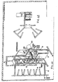
- FIG. 1 is an exemplary perspective view showing an OETO apparatus for continuous unwinding of yarns
- FIG. 2 is an exemplary top plan view of the apparatus for unwinding yarns shown in FIG. 1 ;
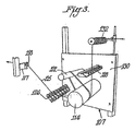
- Fig. 3 is an exemplary detailed view of the drive control assembly
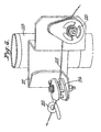
- Fig. 4 is an exemplary detailed perspective view of the path of the yarn through a guiding system that passes the yarn from the active of standby packages to the drive roll;
- Fig. 5A is an exemplary exterior view of the electrical control box
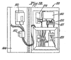
- Fig. 5B is an exemplary interior of the electrical control box
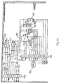
- Fig. 5C is an exemplary schematic diagram of the electrical control box
- FIG. 6A is an exemplary perspective view showing an OETO apparatus for continuous unwinding of yarns
- FIG. 6B is an exemplary top plan view of the apparatus for unwinding yarns shown in FIG. 6A ;
- Fig. 6C is a parts list for FIG. 6A ;
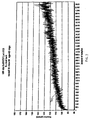
- Fig. 7 is an exemplary graph showing test results of tension measurements on a yarn without anti-tack additives using the OETO apparatus of the present invention.
- Fig. 8 is another exemplary graph showing test results of tension measurements on a yarn without anti-tack additives using the OETO apparatus of the present invention.
- Fig. 9 is an exemplary graph showing test results of tension measurements on a yarn with anti-tack additives using the OETO apparatus of the present invention.
- Fig. 10 is another exemplary graph showing test results of tension measurements on a yarn with anti-tack additives using the OETO apparatus of the present invention.
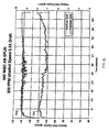
- Fig. 11 is an exemplary graph showing tension measurement test results on a yarn on a rewound package using the OETO apparatus of the present invention.
- Fig. 12 is an exemplary graph showing tension measurement test results on an as-spun with anti-tack OETO yarn package that is unwound with the OETO apparatus of the present invention.
- the apparatus for unwinding yarns of the present invention allows for the cost efficient use of an OETO method with rewound yarn and/or as-spun OETO yarn with anti-tack additives.
- the apparatus of the present invention continuously unwinds as-spun OETO yarns and delivers a relatively constant yarn tension in a relatively small footprint. This provides for improved efficiency in manufacturing processes.
- Fig. 1 is an exemplary perspective view showing one embodiment of the apparatus of the present invention for continuous unwinding of yarns.
- Fig. 1 shows a frame 110 with two pivoting legs 111, 113 that are connected to a central leg portion 109 shown in Fig. 1 as two parallel posts with bridging supports therebetween. Central leg 109 thus extends from one side of frame 110 in the embodiment shown in Fig. 1 .
- the pivoting legs 111, 113 contain pivoting yarn holding arms 120 ( Fig. 2 ).
- the pivoting yarn holding arms 120 hold creels for up to eight packages 105 on each,of the pivoting legs 111, 113.
- the packages 105 may be either active packages or standby packages.
- the pivoting legs 111, 113 of the frame 110 are set at acute angles ( ⁇ 1 , ⁇ 2 ) relative to the central leg 109 in order to provide a versatile and small footprint for the frame 110.
- the acute angles ( ⁇ 1 , ⁇ 2 ) are in the range of 0° to 90°.
- the frame can be configured with various orientations of the two pivoting legs 111, 113 to optimize space on a manufacturing floor.
- Fig. 1 shows first yarn guides 117 and a drive control assembly 107 that are attached to the central leg 109 of frame 110.
- the drive control assembly 107 further comprises a drive motor 112, a drive roll 114, an electrical control box 118, a separator roll 122, second yarn guides 126, break sensors 128, and third yarn guides 132.
- a non-limiting value for the number of first yarn guides 117, second yarn guides 126, break sensors 128 and third yarn guides 132 is eight.
- the drive control assembly 107 is shown in greater detail Fig. 3 below.
- a non-limiting example of an active and a standby package 105 is a full 3 kg creel package of a wound fiber or yarn. While not wishing to be limited, an exemplary yarn for OETO unwinding is spandex (segmented polyurethane), such as LYCRA® sold by INVISTA (formerly DuPont).
- the active and standby packages 105 typically occupy either of two adjacent pivoting yarn holding arms 120 positions on the small footprint frame 110.
- the pivoting yarn holding arms 120 pivot for easy access to the active and standby packages 105.
- the pivoting yarn holding arms 120 hold regular yarn tube cores (e.g., as-spun OETO material).
- Fig. 2 is a top plan view of the apparatus for unwinding yarns shown in Fig. 1 .
- the frame 110 is designed to provide a versatile configuration and a small footprint by placing the two pivoting legs 111, 113 of the frame 110 that hold the packages 105 at acute angles acute angles ( ⁇ 1 , ⁇ 2 ) relative to the central leg 109. Because the two legs 111, 113 can be moved and because the frame 110 has a small footprint, the present invention takes up less floor space in a manufacturing environment.
- Fig. 3 shows a more detailed view of the drive control assembly 107.
- the drive roll 114 is mounted below the separator roll 122.
- the second yarn guides 126 are mounted on either side of the separator roll 122.
- the second yarn guides 126 are mounted before the separator roll 122, and before and lateral to the dive roll 114.
- the break sensors 128 are mounted above and to the right of the drive roll 114.
- the third yarn guides 132 are mounted above and after each of the separator roll 122, drive roll 114 and brook sensors 128.
- the third yarn guides 132 may be mounted on the drive control assembly front panel 130 or on the small foot print frame 110. The position of the third yarn guides 132 relative to the separator roll 122, drive roll 114 and break sensors 128, is as discussed above.
- Fig. 3 shows multiple wraps of yarn around the drive roll 114.
- the multiple wraps of yarn around the drive roll 114 ensure positive feeding without yarn slippage. This helps to avoid entanglement and breakage that occurred with background art OETO apparatus.
- Fig. 4 shows the details of the path of the yarn through a guiding system that passes the yarn/fiber 125 from the active or standby packages 105 to the drive roll 114.
- Pivoting guide brackets 117 are mounted on sleeves 119 that allow the pivoting guide brackets 117 to pivot on the central leg 109 of the frame 110.
- the pivoting guide brackets 117 are secured in a particular position with a securing screw 121.
- the pivoting guide brackets 117 are adjusted in accordance with the acute angles at which the pivoting legs 111, 113 are set.
- the pivoting brackets 117 include, but are not limited to, a pigtail guide 115 and yarn guides 116, 118 that direct the yarn to the second yarn guides 126 attached to the drive control assembly panel 130.
- pigtail guides 115 in this path increases the ease of loading/stringing-up the active and standby packages in comparison to the use of eyelets in the background art apparatus.
- Horizontally mounted yarn guide 116 is positioned closest to the pigtail guide 115 and vertically mounted yarn guide 118 is positioned on a vertical surface of the bracket on a vertical surface of the bracket 117.
- the yarn/fiber 125 is selected from those referred to as spandex or segmented polyurethane.
- spandex or segmented polyurethane.
- a particularly preferred spandex is offered under the Lycra® trademark and can be obtained from INVISTA® INCORPORATED, 4417 Lancaster Pike, Wilmington, Delaware 19805.
- Preferred grades of Lycra® spandex include, but are not limited to: Type 151 and Type 262P.
- the fabricated parts for the frame can be obtained, for example, from Industrial Machine Works; 444 North Bayard Avenue, Waynesboro, Virginia USA.
- the motor and electrical control box 118 cabinet can be obtained, for example, from MSC Industrial Supply Company, 75 Maxess Road, Melville, New York USA.
- the components comprising the electrical control box 118 can be purchased, for example, from Control Corporation of America, 1255 Trapper Circle NW, Roanoke, VA 24012.
- Fig. 5A is a front view of the electrical control box 118 .
- Fig. 5A shows a drive access panel 140, power disconnect switch 142 and mode selector switch 143 that are mounted on the access door 144 of the electrical control box 118.
- Fig. 5B shows a view of the interior of the electrical control box 118.
- Fig. 5B shows terminal blocks 152, 156 that provide an interface convection for signals for the components of the electrical control box 118.
- the major components of the electrical control box 118 include, but are not limited to, a master encoder 150 (not shown), power supply 154, drive motor controller 153, relay 157, break detector interface 158 (not shown) and digital converter 160 .
- a schematic diagram showing the interconnection of these components is set out in Fig. 5C .
- the break detector interface 158 and the drive motor controller 153 are electrically connected to the break detectors 128 and the drive motor 112, respectively, of the drive control assembly 107.
- the master encoder 150 may be provided externally and the break detector interface 158 may be a part of the break detectors 128.
- the motor and electrical control box 118 cabinet can be obtained, for example, from MSC Industrial Supply Company, 75 Maxess Road, Melville, New York USA.
- the components comprising the electrical control box 118 can be purchased, for example, from Control Corporation of America, 1255 Trapper Circle NW, Roanoke, VA 24012.
- An alternative configuration (not shown) for the frame 110 would mount a second yarn holding arm, located at an angle of 180° relative to each of the existing pivoting yarn holding arms, on the frame. This alternative configuration would permit one to hand additional yarn creels on the small footprint frame 110, thus providing more active and standby packages 105 ready for use in the manufacturing process.
- FIG. 6A is another exemplary perspective view showing an OETO apparatus for continuous unwinding of yarns.
- FIG. 6B is an exemplary top plan view of the apparatus for unwinding yarns shown in FIG. 6A .
- Fig. 6C is a parts list for FIG. 6A ;
- the fabricated parts for FIG. 6A can be obtained, for example, from Industrial Machine Works, 444 North Bayard Avenue, Waynesboro, Virginia USA. Fabricated parts are indicated by "D" numbers in the parts list of Fig. 6C .
- the motor and electrical control box cabinet of FIG. 6A can be obtained, for example, from MSC Industrial Supply Company, 75 Maxess Road, Melville, New York USA.
- the components comprising the electrical control box can be purchased, for example, from Control Corporation of America, 1255 Trapper Circle NW, Roanoke, VA 24012.
- Fig. 7 to Fig. 12 are exemplary graphs of test results using the OETO apparatus of the present invention.
- the yarn/fiber used for tests is selected from those referred to as spandex or segmented polyurethane.
- spandex or segmented polyurethane.
- a particularly preferred spandex is offered under the Lycra® trademark and can be obtained from INVISTA® INCORPORATED, 4417 Lancaster Pike, Wilmington, Delaware 19805.
- Preferred grades of Lycra® spandex include, but are not limited to: Type 151 and Type 262P.
- the concentration of anti-tack additives is in the range of 0.05% to 1%.
- the legend of each figures gives parameters particular to the test such as unwind and take-up speed in feet-per-minute (FPM).
- the legend of each figure also indicates the lot number of the yarns, test date and the age of the yarns-under-test.
- Fig. 7 is an exemplary graph showing test results of tension measurements on a yarn without anti-tack additives using the OETO apparatus of the present invention.
- the yarn tension 701 starts out at about 95 grams and climbs to about 140 grams at the end of the test cycle. This corresponds to an increase of about 47% in the yarn tension.
- Fig. 8 is an exemplary graph showing test results of tension measurements on a yarn without anti-tack additives using the OETO apparatus of the present invention.
- the yarn tension 801 starts out at about 95 grams and climbs to about 150 grams at the end of the test cycle. This corresponds to an increase of about 58% in the yarn tension.
- the graph of Fig. 8 shows brief spikes in the yarn tension up to the maximum measurement value of 180 grams. Moreover, the yarn could not be unwound to the core of the creel.
- Fig. 9 is an exemplary graph showing test results of tension measurements on a yarn with a low level of anti-tack additives using the OETO apparatus of the present invention.
- the yarn tension 901 starts out at about 100 grams and climbs to about 120 grams at the end of the test cycle. This corresponds to an increase of about 20% in the yarn tension. Though this is a relatively constant value for yarn tension, there were still breaks in the yarn during the unwinding method, as illustrated in Fig. 9 .
- Fig. 10 is an exemplary graph showing test results of tension measurements on a yarn with anti-tack additives using the OETO apparatus of the present invention.
- the yarn tension 1001 starts out at about 100 grams and climbs to about 120 grams at the end of the test cycle. This corresponds to an increase of about 20% in the yarn tension.
- Fig. 11 is an exemplary graph showing tension measurement test results on a yarn on a rewound package using the OETO apparatus of the present invention.
- Fig. 11 shows both the package side yarn tension 1101 and the machine side yarn tension 1103.
- Fig. 11 shows a package side yarn tension 1101 for a typical rewound package.
- the package side yarn tension starts out at about 80 grams and climbs to about 140 grams at the end of the test cycle. This corresponds to an increase of about 75% in the yarn tension.
- Fig. 12 is an exemplary graph showing tension measurements test results on an as-spun OETO with anti-tack yarn package that is unwound with the method and apparatus of the present invention.
- Fig. 12 demonstrates the desired relatively constant yarn tension.
- Fig. 12 also shows both the package side yarn tension 1201 and the machine side yarn tension 1203.
- the graph of Fig. 12 shows a package side tension 1201 that starts out at about 110 grams and only climbs to a maximum of 125 grams at the end of the test cycle.
- Fig. 11 which showed a 75% increase in yarn tension
- these test results indicate that the method and apparatus for unwinding of the present invention experiences an increase of only a 14% in yarn tension.
- FIG. 13 shows a configuration of the active package relative to the central leg 109 of the frame 110 of the invention.
- active packages 105 are maintained in a desired orientation by pivoting yarn holders 120 ( Fig. 2 ).
- the diameter of the pivoting yarn holders 120 is smaller than the diameter of the open core of the active package 105 such that the active packages 105 can be slid over the suitably positioned pivoting yarn holder 120 and such that the yarn 125 ( Fig. 4 ) can be unwound from the active package 105 by the OETO apparatus of the present invention.
- the yarn 125 ( Fig. 4 ) is then directed to the drive control assembly 107 for the unwinding process.
- a distance (d) between the active packages 105 and the first yarn guides 117 which is at least about 0.34 meter and preferably not more than about 0.91 meter, can be maintained for operation with high tack fibers.
- the directional change of the yarn 125, as it passes through a first yarn guide 117, as measured in terms of ⁇ , is preferably limited to between 0° and about 30° for yarns with tack levels greater than about 2 and less than about 7.5, and between 0° and about 10° for fibers with tack levels greater than about 7.5. Larger angles can result in excessive variations in thread line tension and draft, or even yarn breakage.
- the method and apparatus of the present invention provides an OETO method and apparatus for unwinding yarns with anti-tack additives that can be implemented in a relatively small footprint and avoids the problems of entanglement, breakage and increased manufacturing costs of the background art.
Applications Claiming Priority (2)
| Application Number | Priority Date | Filing Date | Title |
|---|---|---|---|
| US58834904P | 2004-07-16 | 2004-07-16 | |
| PCT/US2005/025327 WO2006025955A1 (en) | 2004-07-16 | 2005-07-15 | Continuous yarn delivery crell |
Publications (2)
| Publication Number | Publication Date |
|---|---|
| EP1784352A1 EP1784352A1 (en) | 2007-05-16 |
| EP1784352B1 true EP1784352B1 (en) | 2011-01-26 |
Family
ID=35262072
Family Applications (1)
| Application Number | Title | Priority Date | Filing Date |
|---|---|---|---|
| EP05778489A Not-in-force EP1784352B1 (en) | 2004-07-16 | 2005-07-15 | Continuous yarn delivery creel |
Country Status (9)
| Country | Link |
|---|---|
| US (1) | US7527216B2 (zh) |
| EP (1) | EP1784352B1 (zh) |
| JP (1) | JP4917536B2 (zh) |
| KR (1) | KR101169112B1 (zh) |
| CN (1) | CN101035730B (zh) |
| BR (1) | BRPI0513126A (zh) |
| DE (1) | DE602005026131D1 (zh) |
| MX (1) | MX2007000552A (zh) |
| WO (1) | WO2006025955A1 (zh) |
Families Citing this family (21)
| Publication number | Priority date | Publication date | Assignee | Title |
|---|---|---|---|---|
| KR100659798B1 (ko) * | 2005-12-02 | 2006-12-19 | 주식회사 효성 | 탄성사용 oeto 해사장치 및 이에 의한 해사방법 |
| WO2007079264A2 (en) * | 2005-12-30 | 2007-07-12 | Overend Technologies, Llc | Unwind and feed system for elastomeric thread |
| KR101338765B1 (ko) | 2006-12-28 | 2013-12-06 | 주식회사 효성 | 탄성사의 해사 시에 사절을 방지하는 방법 |
| MX2009011342A (es) * | 2007-04-20 | 2009-11-05 | Invista Tech Sarl | Fileta compacta de desenrollamiento continuo por encima con control de tension. |
| US20090114754A1 (en) * | 2007-11-01 | 2009-05-07 | Invista North America S.A.R.L. | Tube cores for packaging elastomeric filaments |
| EP2163668B1 (de) * | 2008-09-12 | 2013-03-27 | Karl Mayer Textilmaschinenfabrik GmbH | Musterkettenschärmaschine, Drehgatter und Spulenhalter |
| MX355401B (es) * | 2009-12-23 | 2018-04-18 | Invista Tech Sarl | Fibra elastica que contiene un aditivo anti-pegalosidad. |
| CN102167247A (zh) * | 2011-01-19 | 2011-08-31 | 宁国金鑫电机有限公司 | 一种转塔式工件架 |
| US9051151B2 (en) | 2011-11-04 | 2015-06-09 | The Procter & Gamble Company | Splicing apparatus for unwinding strands of material |
| US9132987B2 (en) | 2011-11-04 | 2015-09-15 | The Procter & Gamble Plaza | Apparatus with rotatable arm for unwinding strands of material |
| JP2015504831A (ja) * | 2011-12-22 | 2015-02-16 | ザ プロクター アンド ギャンブルカンパニー | 材料の複数のストランドを巻き戻すための小型機械 |
| CN103710846B (zh) * | 2013-12-18 | 2015-07-01 | 南通苏州大学纺织研究院 | 一种纱线退绕系统 |
| CN106102674A (zh) | 2014-03-17 | 2016-11-09 | 宝洁公司 | 用于制造吸收制品的设备和方法 |
| CN104071633A (zh) * | 2014-06-12 | 2014-10-01 | 吴江久美微纤织造有限公司 | 一种线轴支架 |
| NL2018606B1 (en) * | 2017-03-30 | 2018-10-10 | Vmi Holland Bv | Creel bobbin brake, creel bobbin assembly, a creel and a creel method |
| CN107324143A (zh) * | 2017-08-15 | 2017-11-07 | 晋江市达丽弹性织造有限公司 | 一种弹性带自动卷筒机及卷筒方法 |
| USD938499S1 (en) * | 2019-05-14 | 2021-12-14 | Btsr International S.P.A. | Modular creel |
| EP3771673B1 (en) * | 2019-07-30 | 2023-09-06 | TMT Machinery, Inc. | Peg, package exchanging device, and yarn processing system |
| CN110983609B (zh) * | 2020-01-07 | 2023-09-19 | 浙江理工大学 | 一种纱线接头检测装置及其使用方法 |
| CN111733496B (zh) * | 2020-06-17 | 2021-08-27 | 浙江理工大学 | 一种纱线空筒检测装置及方法 |
| CN112429596B (zh) * | 2020-12-22 | 2021-09-24 | 南通新帝克单丝科技股份有限公司 | 大直径聚合物单丝卷取装置 |
Family Cites Families (18)
| Publication number | Priority date | Publication date | Assignee | Title |
|---|---|---|---|---|
| US1790553A (en) * | 1931-01-27 | peterson | ||
| US1623546A (en) * | 1925-11-11 | 1927-04-05 | Foster Machine Co | Creel |
| US1814203A (en) * | 1928-05-28 | 1931-07-14 | Yates Henry Harrison | Creeling mechanism |
| CH214387A (de) * | 1940-04-08 | 1941-04-30 | Benninger Ag Maschf | Spulengatter für Zettelmaschinen. |
| DE724926C (de) * | 1941-05-22 | 1942-09-10 | Otto F Hueesker Fa | Zettelgatter mit Innenbeschickung |
| US3150845A (en) * | 1959-11-28 | 1964-09-29 | American Enka Corp | Magazine creel |
| US3674223A (en) * | 1971-04-29 | 1972-07-04 | Morris Philip | Yarn creel and method of positioning yarn cones |
| GB1413619A (en) * | 1973-03-05 | 1975-11-12 | Heberlein & Co Ag | Rotatable bobbin creels for stretch-texturing machines |
| US4015314A (en) * | 1976-02-11 | 1977-04-05 | Dixie Yarns, Inc. | Yarn tape deweaving method and apparatus |
| EP0225670B1 (en) * | 1985-12-09 | 1989-05-17 | Picanol N.V. | Process for unwinding a thread from a reel in looms, and arrangement used therefor |
| CH677102A5 (zh) * | 1988-03-30 | 1991-04-15 | Hungerbuehler & Co Ag | |
| US4948067A (en) * | 1989-12-05 | 1990-08-14 | Alandale Industries, Inc. | Textile Yarn Creel |
| CH681003A5 (en) * | 1990-06-21 | 1992-12-31 | Zellweger Uster Ag | Creel frame - has creel peg alignment for loading or working |
| US5732899A (en) * | 1996-04-29 | 1998-03-31 | Wells; William Edgar | Wire reel unwind assembly including wire reel mounting unit |
| US20050133653A1 (en) * | 2001-03-23 | 2005-06-23 | Invista North America S.A R.L. | Tension controlled thread feeding system |
| US20040104299A1 (en) * | 2002-03-19 | 2004-06-03 | Heaney Daniel J. | Unwinder for as-spun elastomeric fiber |
| US6676054B2 (en) * | 2001-03-23 | 2004-01-13 | E. I. Du Pont De Nemours And Company | Unwinder for as-spun elastomeric fiber |
| DE10253341A1 (de) * | 2002-04-26 | 2003-11-13 | Volkmann Gmbh | Spulengatter für Textilmaschinen sowie Betätigungsventil zum Verstellen eines solchen Spulengatters |
-
2005
- 2005-07-15 WO PCT/US2005/025327 patent/WO2006025955A1/en active Application Filing
- 2005-07-15 CN CN2005800302585A patent/CN101035730B/zh not_active Expired - Fee Related
- 2005-07-15 EP EP05778489A patent/EP1784352B1/en not_active Not-in-force
- 2005-07-15 BR BRPI0513126-0A patent/BRPI0513126A/pt not_active IP Right Cessation
- 2005-07-15 US US11/181,902 patent/US7527216B2/en not_active Expired - Fee Related
- 2005-07-15 MX MX2007000552A patent/MX2007000552A/es active IP Right Grant
- 2005-07-15 KR KR1020077003635A patent/KR101169112B1/ko not_active IP Right Cessation
- 2005-07-15 JP JP2007521705A patent/JP4917536B2/ja not_active Expired - Fee Related
- 2005-07-15 DE DE602005026131T patent/DE602005026131D1/de active Active
Also Published As
| Publication number | Publication date |
|---|---|
| EP1784352A1 (en) | 2007-05-16 |
| DE602005026131D1 (de) | 2011-03-10 |
| KR101169112B1 (ko) | 2012-07-27 |
| US20060011771A1 (en) | 2006-01-19 |
| US7527216B2 (en) | 2009-05-05 |
| JP2008506609A (ja) | 2008-03-06 |
| MX2007000552A (es) | 2007-03-07 |
| WO2006025955A1 (en) | 2006-03-09 |
| JP4917536B2 (ja) | 2012-04-18 |
| KR20070038152A (ko) | 2007-04-09 |
| BRPI0513126A (pt) | 2008-04-29 |
| CN101035730B (zh) | 2013-03-20 |
| CN101035730A (zh) | 2007-09-12 |
Similar Documents
| Publication | Publication Date | Title |
|---|---|---|
| EP1784352B1 (en) | Continuous yarn delivery creel | |
| EP1379461B1 (en) | Unwinder and method for unwinding elastomeric fiber | |
| EP2139800A1 (en) | Compact continuous over end take-off (oeto) creel with tension control | |
| KR100253025B1 (ko) | 선조재의 권취 장치 | |
| EP1954860B1 (en) | A compact single mandrel creel for over end take-off thread delivery | |
| EP2150643B1 (en) | Method of folding filament and bundle of filament manufactured thereof | |
| CN101736453B (zh) | 操作自由端纺纱机械的方法以及自由端纺纱机械 | |
| US20050133653A1 (en) | Tension controlled thread feeding system | |
| JP2013511456A (ja) | クリールのモジュラーユニット | |
| US4471917A (en) | Balloon-control guide and yarn rewinding process | |
| CN101657574A (zh) | 自由端纺纱机 | |
| US11427431B2 (en) | Method and system for feeding a twisted braided metal cable or flat wire from a corresponding support without altering the structure or shape of the wire | |
| US6279307B1 (en) | Tension control method using fluff control device | |
| US20040104299A1 (en) | Unwinder for as-spun elastomeric fiber | |
| CN105274662A (zh) | 纱线蓄留装置、纱线卷绕单元以及纱线卷绕机 | |
| KR200234146Y1 (ko) | 연선기 | |
| JPH08190864A (ja) | 一体型スリットボビン偏向ヨークコイル巻線装置 | |
| CN116620952A (zh) | 用于对卷绕机中的喂给筒管称重的装置 | |
| JP2000143093A (ja) | 線状体のスクリーニング装置 | |
| JP2001146364A (ja) | 巻取り装置 | |
| JPH0535862U (ja) | 精紡機のロービングガイド |
Legal Events
| Date | Code | Title | Description |
|---|---|---|---|
| PUAI | Public reference made under article 153(3) epc to a published international application that has entered the european phase |
Free format text: ORIGINAL CODE: 0009012 |
|
| 17P | Request for examination filed |
Effective date: 20070118 |
|
| AK | Designated contracting states |
Kind code of ref document: A1 Designated state(s): CH DE FR GB IT LI |
|
| RIN1 | Information on inventor provided before grant (corrected) |
Inventor name: MANNING, THOMAS, W., JR. Inventor name: BING-WO, RONALD D. |
|
| DAX | Request for extension of the european patent (deleted) | ||
| RBV | Designated contracting states (corrected) |
Designated state(s): CH DE FR GB IT LI |
|
| 17Q | First examination report despatched |
Effective date: 20071221 |
|
| GRAP | Despatch of communication of intention to grant a patent |
Free format text: ORIGINAL CODE: EPIDOSNIGR1 |
|
| RTI1 | Title (correction) |
Free format text: CONTINUOUS YARN DELIVERY CREEL |
|
| GRAS | Grant fee paid |
Free format text: ORIGINAL CODE: EPIDOSNIGR3 |
|
| GRAA | (expected) grant |
Free format text: ORIGINAL CODE: 0009210 |
|
| AK | Designated contracting states |
Kind code of ref document: B1 Designated state(s): CH DE FR GB IT LI |
|
| REG | Reference to a national code |
Ref country code: GB Ref legal event code: FG4D |
|
| REG | Reference to a national code |
Ref country code: CH Ref legal event code: EP |
|
| REF | Corresponds to: |
Ref document number: 602005026131 Country of ref document: DE Date of ref document: 20110310 Kind code of ref document: P |
|
| REG | Reference to a national code |
Ref country code: DE Ref legal event code: R096 Ref document number: 602005026131 Country of ref document: DE Effective date: 20110310 |
|
| PLBE | No opposition filed within time limit |
Free format text: ORIGINAL CODE: 0009261 |
|
| STAA | Information on the status of an ep patent application or granted ep patent |
Free format text: STATUS: NO OPPOSITION FILED WITHIN TIME LIMIT |
|
| 26N | No opposition filed |
Effective date: 20111027 |
|
| REG | Reference to a national code |
Ref country code: DE Ref legal event code: R097 Ref document number: 602005026131 Country of ref document: DE Effective date: 20111027 |
|
| REG | Reference to a national code |
Ref country code: CH Ref legal event code: PL |
|
| PG25 | Lapsed in a contracting state [announced via postgrant information from national office to epo] |
Ref country code: CH Free format text: LAPSE BECAUSE OF NON-PAYMENT OF DUE FEES Effective date: 20110731 Ref country code: LI Free format text: LAPSE BECAUSE OF NON-PAYMENT OF DUE FEES Effective date: 20110731 |
|
| REG | Reference to a national code |
Ref country code: FR Ref legal event code: PLFP Year of fee payment: 11 |
|
| PGFP | Annual fee paid to national office [announced via postgrant information from national office to epo] |
Ref country code: GB Payment date: 20150715 Year of fee payment: 11 Ref country code: DE Payment date: 20150707 Year of fee payment: 11 |
|
| PGFP | Annual fee paid to national office [announced via postgrant information from national office to epo] |
Ref country code: FR Payment date: 20150629 Year of fee payment: 11 |
|
| PGFP | Annual fee paid to national office [announced via postgrant information from national office to epo] |
Ref country code: IT Payment date: 20150727 Year of fee payment: 11 |
|
| REG | Reference to a national code |
Ref country code: DE Ref legal event code: R119 Ref document number: 602005026131 Country of ref document: DE |
|
| GBPC | Gb: european patent ceased through non-payment of renewal fee |
Effective date: 20160715 |
|
| PG25 | Lapsed in a contracting state [announced via postgrant information from national office to epo] |
Ref country code: FR Free format text: LAPSE BECAUSE OF NON-PAYMENT OF DUE FEES Effective date: 20160801 Ref country code: DE Free format text: LAPSE BECAUSE OF NON-PAYMENT OF DUE FEES Effective date: 20170201 |
|
| REG | Reference to a national code |
Ref country code: FR Ref legal event code: ST Effective date: 20170331 |
|
| PG25 | Lapsed in a contracting state [announced via postgrant information from national office to epo] |
Ref country code: GB Free format text: LAPSE BECAUSE OF NON-PAYMENT OF DUE FEES Effective date: 20160715 |
|
| PG25 | Lapsed in a contracting state [announced via postgrant information from national office to epo] |
Ref country code: IT Free format text: LAPSE BECAUSE OF NON-PAYMENT OF DUE FEES Effective date: 20160715 |