EP1784342B1 - Dispositif de conditionnement d'elements de fixation - Google Patents
Dispositif de conditionnement d'elements de fixation Download PDFInfo
- Publication number
- EP1784342B1 EP1784342B1 EP05786079A EP05786079A EP1784342B1 EP 1784342 B1 EP1784342 B1 EP 1784342B1 EP 05786079 A EP05786079 A EP 05786079A EP 05786079 A EP05786079 A EP 05786079A EP 1784342 B1 EP1784342 B1 EP 1784342B1
- Authority
- EP
- European Patent Office
- Prior art keywords
- supporting part
- cylindrical
- fixation components
- notches
- cylindrical stem
- Prior art date
- Legal status (The legal status is an assumption and is not a legal conclusion. Google has not performed a legal analysis and makes no representation as to the accuracy of the status listed.)
- Expired - Lifetime
Links
Images


Classifications
-
- F—MECHANICAL ENGINEERING; LIGHTING; HEATING; WEAPONS; BLASTING
- F16—ENGINEERING ELEMENTS AND UNITS; GENERAL MEASURES FOR PRODUCING AND MAINTAINING EFFECTIVE FUNCTIONING OF MACHINES OR INSTALLATIONS; THERMAL INSULATION IN GENERAL
- F16B—DEVICES FOR FASTENING OR SECURING CONSTRUCTIONAL ELEMENTS OR MACHINE PARTS TOGETHER, e.g. NAILS, BOLTS, CIRCLIPS, CLAMPS, CLIPS OR WEDGES; JOINTS OR JOINTING
- F16B15/00—Nails; Staples
- F16B15/08—Nails; Staples formed in integral series but easily separable
-
- F—MECHANICAL ENGINEERING; LIGHTING; HEATING; WEAPONS; BLASTING
- F16—ENGINEERING ELEMENTS AND UNITS; GENERAL MEASURES FOR PRODUCING AND MAINTAINING EFFECTIVE FUNCTIONING OF MACHINES OR INSTALLATIONS; THERMAL INSULATION IN GENERAL
- F16B—DEVICES FOR FASTENING OR SECURING CONSTRUCTIONAL ELEMENTS OR MACHINE PARTS TOGETHER, e.g. NAILS, BOLTS, CIRCLIPS, CLAMPS, CLIPS OR WEDGES; JOINTS OR JOINTING
- F16B13/00—Dowels or other devices fastened in walls or the like by inserting them in holes made therein for that purpose
Definitions
- the subject of the present invention is a device for packaging fastening elements comprising a first part constituted by a support piece and a second part comprising a screw which engages in a central orifice of the support part during screwing.
- these fastening elements being detachably mountable on a flexible support profile so as to constitute an easily transportable band which can be used to supply an automated apparatus for fastening mechanical elements by screwing (see for example the document EP-A-0 935 969 ).
- the fasteners serve in particular, but not exclusively, to secure insulation board membranes and roofing over a roof infrastructure.
- the volume of the fasteners even if it has been reduced, remains important especially if the number of screws required is large more, transportation and packaging of the support pieces are not facilitated.
- the invention therefore more particularly aims to reduce these disadvantages. It relates more particularly to fastening elements each comprising a bearing piece provided with an orifice for the passage of a fixing screw, this bearing piece being integral with a shaft which extends and opens coaxially to said orifice .
- the device uses a flexible support profile having at least partly the shape of a band whose lateral edge is provided with a succession of notches opening laterally outwards through a narrowed opening of width less than the diameter of the barrels so that said barrels can be engaged and be held in the notches by clipping.
- the support pieces and the notches are shaped in such a way that each support piece partially covers the one located in its immediate vicinity so that the distance between two adjacent drums is substantially equal to the sum of the radius the head of the support piece and the radius of the barrel if the support piece has a cylindrical shape or, at half the width of the head of the support piece and the radius of the barrel if the piece support has a rectangular shape.
- the flexible support profile according to the invention can be used in particular with an apparatus for screwing fasteners on which are screwed screws such as the subject of the patent FR-A-2 796 872 supra.
- the support profile can also be used with an apparatus for screwing the fastening elements with screws supplied separately in this case, the flexible support profile comprises notches on which clips are attached to a fastener barrel, the insertion of the screw into the barrel is carried out automatically by the device.
- the junction of the support piece and the barrel is constituted by a flange comprising radial ribs arranged regularly around the base of the barrel, these ribs in particular making it possible to stiffen the flange and to ensure a better contact between said blank support and the support on which is fixed the screw preventing the rotation of this support part relative to this support.
- Each support piece may also include on its underside pins to improve the adhesion between the support part and the support on which is fixed the screw thus reducing the play that may exist between these two elements.
- the device according to the invention 1 comprises a flexible support profile 2 having substantially the shape of a strip and made of plastic or semi-rigid cardboard.
- the flexible support profile 2 comprises a lateral edge provided with a succession of notches 3 spaced at regular intervals and opening laterally to the outside through a narrowed opening 4 of substantially cylindrical shape.
- the device according to the invention 1 as represented on the figure 2 also comprises fastening elements 5 comprising a support piece 6, having the shape of a washer that can be molded plastic or stamped sheet metal, and provided with an orifice 7 formed at the bottom of a concavity for receiving the head of a fixing screw.
- Each support piece 6 is integral with a tubular shaft 8 which extends and opens coaxially with said orifice 7.
- the inside diameter of the shaft 8 is provided so that the head of the screw can engage and come abutting in its lower part against a shoulder initiating a reduction of the diameter.
- the drums 8 engage and are held in the notches 3 of the flexible support profile 2 by clipping in said narrowed openings 4 which each have a width less than the diameter of the barrels 8, the distance between two adjacent screws being equal to the sum the radius of the head of the support piece 6 and the radius of the shaft 8, each support part 6 partially overlaps that located in its immediate vicinity.
- the support piece 9 has substantially the shape of a rectangular plate, molded plastic or stamped sheet metal, and provided with an orifice 7 formed at the bottom of a concavity for receiving the head of the screw.
- the spacing between two adjacent screws is then substantially equal to half the width of the head of the support piece 9 and the radius of the barrel 8.
- the flexible support profile 2 on which the support parts 6, 9 are attached is introduced into the apparatus magazine for screwing fastening elements 5, the user then extracts it by performing on the end superior of the latter a traction oriented perpendicularly to the axis of the barrels 8.
- the flexible support profile 2 which comprises notches 3 into which clips 6, 9 connected to a tubular shaft 8 are loaded into a automatic screwing device, the screw being either pre-assembled in the barrel 8 or inserted automatically into the barrel 8 by the laying device.
- the junction of the support piece 9 and the shaft 8 is constituted by a flange 10 comprising radial ribs 11, arranged regularly around the base of the shaft 8, these ribs 11 making it possible in particular to stiffen the flange 10 and to ensure better contact between said support piece 9 and the support on which is fixed the screw preventing the rotation of the support piece 9 relative to this support.
- each support piece 9 may also comprise on its underside pins 12 for improving the adhesion between the support piece 9 and the support on which is fixed the screw thus reducing the play that can exist between these two elements.
Landscapes
- Engineering & Computer Science (AREA)
- General Engineering & Computer Science (AREA)
- Mechanical Engineering (AREA)
- Clamps And Clips (AREA)
- Devices For Blowing Cold Air, Devices For Blowing Warm Air, And Means For Preventing Water Condensation In Air Conditioning Units (AREA)
- Containers And Plastic Fillers For Packaging (AREA)
- Packages (AREA)
- Basic Packing Technique (AREA)
- Packaging Of Annular Or Rod-Shaped Articles, Wearing Apparel, Cassettes, Or The Like (AREA)
- Cartons (AREA)
- Connection Of Plates (AREA)
- Mounting, Exchange, And Manufacturing Of Dies (AREA)
Description
- La présente invention a pour objet un dispositif de conditionnement d'éléments de fixation comprenant une première partie constituée par une pièce d'appui et une deuxième partie comportant une vis qui s'engage dans un orifice central de la pièce d'appui lors du vissage, ces éléments de fixation pouvant être montés de façon détachable sur un profilé de supports souple afin de constituer une bande facilement transportable et pouvant servir à alimenter un appareil automatisé servant à la fixation par vissage d'éléments mécaniques (voir par exemple le document
EP-A-0 935 969 ). - Les éléments de fixation servent notamment, mais non exclusivement, à la fixation de membranes de panneaux isolants et de couverture sur une infrastructure de toit.
- On sait que pour faciliter une telle fixation et pour réduire le délai de l'opération, on utilise de plus en plus souvent des appareils de vissage automatique comprenant un magasin dans lequel sont stockés une pluralité d'éléments de fixation de ce type.
- Ainsi, on a déjà proposé dans le brevet
FR-A-2 796 872 - Néanmoins, cette solution présente l'inconvénient d'utiliser des éléments de fixation dont les vis sont préengagées dans les perçages des pièces d'appui or, ces éléments de fixation sont relativement volumineux et, par conséquent, difficilement conditionnables et stockables.
- Afin de réduire cet inconvénient, la Demanderesse a proposé dans le brevet
EP-A-1 405 697 au nom de LR ETANCO un appareil permettant le vissage d'éléments de fixation dont les vis et les pièces d'appui sont alimentées séparément, leur assemblage ne s'effectuant qu'au moment du vissage. Les vis utilisées sont montées de façon détachable sur des profilés de supports souples de manière à être disposées parallèlement les unes aux autres et espacées les unes des autres d'une distance prédéterminée (pas) en formant une bande. - De cette façon, les éléments de fixation utilisés par cet appareil sont moins volumineux et les vis montées sur des profilés de supports souples sont plus facilement conditionnables et stockables.
- Néanmoins, le volume des éléments de fixation, même s'il a été réduit, demeure important surtout si le nombre de vis nécessaires est grand de plus, le transport et le conditionnement des pièces d'appui ne s'en trouvent pas facilitées.
- L'invention a donc plus particulièrement pour but de réduire ces inconvénients. Elle concerne plus particulièrement des éléments de fixation comprenant chacun une pièce d'appui munie d'un orifice servant au passage d'une vis de fixation, cette pièce d'appui étant solidaire d'un fût qui s'étend et débouche coaxialement audit orifice.
- Selon l'invention, le dispositif met en oeuvre un profilé de supports souple présentant au moins en partie la forme d'une bande dont une bordure latérale est munie d'une succession d'encoches débouchant latéralement à l'extérieur par une ouverture rétrécie de largeur inférieure au diamètre des fûts de manière à ce que lesdits fûts puissent être engagés et être maintenus dans les encoches par clipsage.
- Les pièces d'appui ainsi que les encoches sont conformées d'une telle façon que chaque pièce d'appui recouvre partiellement celle située à sa proximité immédiate de manière à ce que l'entraxe entre deux fûts adjacents soit sensiblement égal à la somme du rayon de la tête de la pièce d'appui et du rayon du fût si la pièce d'appui présente une forme cylindrique ou alors, à la moitié de la largeur de la tête de la pièce d'appui et du rayon du fût si la pièce d'appui présente une forme rectangulaire.
- De cette façon, les éléments de fixation sont plus faciles à stocker, à transporter et à utiliser. Ainsi, le profilé de supports souple selon l'invention peut être utilisé notamment avec un appareil permettant le vissage d'éléments de fixation sur lesquels sont prévissées des vis tel que celui faisant l'objet du brevet
FR-A-2 796 872 - Avantageusement, la jonction de la pièce d'appui et du fût est constituée par une collerette comprenant des nervures radiales disposées régulièrement autour de la base du fût, ces nervures permettant notamment de rigidifier la collerette et d'assurer un meilleur contact entre ladite pièce d'appui et le support sur lequel est fixé la vis en prévenant la rotation de cette pièce d'appui par rapport à ce support.
- Chaque pièce d'appui pourra également comprendre sur sa face inférieure des picots permettant d'améliorer l'adhérence entre la pièce d'appui et le support sur lequel est fixé la vis réduisant ainsi le jeu pouvant exister entre ces deux éléments.
- Un mode d'exécution de l'invention sera décrit ci-après, à titre d'exemples non limitatifs, avec référence aux dessins annexés, dans lesquels :
- La
figure 1 est une vue en perspective d'un profilé de supports souple. - La
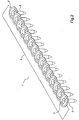
figure 2 est une vue en perspective d'un profilé de supports souple comprenant des éléments de fixation comportant une pièce d'appui, dont la tête présente une forme circulaire. - La
figure 3 est une vue en perspective d'un profilé de supports souple comprenant des éléments de fixation comportant une pièce d'appui, dont la tête présente une forme rectangulaire. - La
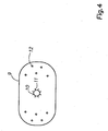
figure 4 est une vue en perspective de la face inférieure de la tête d'une pièce d'appui. - Dans l'exemple représenté sur la
figure 1 , le dispositif selon l'invention 1 comprend un profilé de supports souple 2 présentant sensiblement la forme d'une bande et constitué de matière plastique ou de carton semi-rigide. - Le profilé de supports souple 2 comprend une bordure latérale munie d'une succession d'encoches 3 espacées à intervalles réguliers et débouchant latéralement à l'extérieur par une ouverture rétrécie 4 de forme sensiblement cylindrique.
- Le dispositif selon l'invention 1 tel que représenté sur la
figure 2 comprend également des éléments de fixation 5 comportant une pièce d'appui 6, présentant la forme d'une rondelle pouvant être en matière plastique moulée ou en tôle emboutie, et munie d'un orifice 7 formé au fond d'une concavité destinée à recevoir la tête d'une vis de fixation. - Chaque pièce d'appui 6 est solidaire d'un fût tubulaire 8 qui s'étend et débouche coaxialement audit orifice 7. Le diamètre intérieur du fût 8 est prévu de manière à ce que la tête de la vis puisse s'y engager et venir en butée dans sa partie inférieure contre un épaulement amorçant une réduction du diamètre.
- Les fûts 8 s'engagent et sont maintenus dans les encoches 3 du profilé de supports souple 2 par clipsage dans lesdites ouvertures rétrécies 4 qui présentent chacune une largeur inférieure au diamètre des fûts 8, l'entraxe entre deux vis adjacentes étant égale à la somme du rayon de la tête de la pièce d'appui 6 et du rayon du fût 8, chaque pièce d'appui 6 recouvre partiellement celle située à sa proximité immédiate.
- Dans l'exemple représenté sur la
figure 3 , la pièce d'appui 9 présente sensiblement la forme d'une plaquette rectangulaire, en matière plastique moulée ou en tôle emboutie, et munie d'un orifice 7 formé au fond d'une concavité destinée à recevoir la tête de la vis. - L'entraxe entre deux vis adjacentes est alors sensiblement égale à la moitié de la largeur de la tête de la pièce d'appui 9 et du rayon du fût 8.
- Le profilé de supports souple 2 sur lequel sont attachées les pièces d'appui 6, 9 est introduit dans le magasin de l'appareil permettant le vissage d'éléments de fixation 5, l'utilisateur l'extrait ensuite en effectuant sur l'extrémité supérieure de celui-ci une traction axée perpendiculairement à l'axe des fûts 8.
- Le profil de supports souple 2 qui comprend des encoches 3 dans lesquelles se clipsent des pièces d'appui 6, 9 liées à un fût tubulaire 8 est chargé dans un appareil de vissage automatique, la vis étant soit prémontée dans le fût 8, soit insérée automatiquement dans le fût 8 par l'appareil de pose.
- Avantageusement, tel que cela est représenté sur la
figure 4 , la jonction de la pièce d'appui 9 et du fût 8 est constituée par une collerette 10 comprenant des nervures radiales 11, disposées régulièrement autour de la base du fût 8, ces nervures 11 permettant notamment de rigidifier la collerette 10 et d'assurer un meilleur contact entre ladite pièce d'appui 9 et le support sur lequel est fixé la vis en prévenant la rotation de cette pièce d'appui 9 par rapport à ce support. - De manière avantageuse, chaque pièce d'appui 9 pourra également comprendre sur sa face inférieure des picots 12 permettant d'améliorer l'adhérence entre la pièce d'appui 9 et le support sur lequel est fixé la vis réduisant ainsi le jeu pouvant exister entre ces deux éléments.
Claims (6)
- Dispositif de conditionnement (1) d'éléments de fixation (5), comportant:• des éléments de fixation (5) comprenant chacun une pièce d'appui (6, 9) munie d'un orifice (7) servant au passage d'une vis de fixation, cette pièce d'appui (6, 9) étant solidaire d'un fût (8) qui s'étend et débouche coaxialement audit orifice (7);• un profilé de supports souple (2) présentant au moins en partie la forme d'une bande dont une bordure latérale est munie d'une succession d'encoches (3) débouchant latéralement à l'extérieur par une ouverture rétrécie (4) de largeur inférieure au diamètre des fûtes (8) de manière à ce que lesdits fûts (8) puissent être engagés et être maintenus dans les encoches (3) par clipsage; caractérisé en ce queles pièces d'appui (6, 9) ainsi que les encoches (3) sont conformées d'une telle façon que chaque pièce d'appui (6, 9) recouvre partiellement celle située à sa proximité immédiate de manière à ce que l'entraxe entre deux fûts adjacents (8) soit sensiblement égal à la somme du rayon de la tête de la pièce d'appui (6, 9) et du rayon du fût (8) si la pièce d'appui (6) présente une forme cylindrique ou alors, à la moitié de la largeur de la tête de la pièce d'appui (6, 9) et du rayon du fût (8) si la pièce d'appui (9) présente une forme rectangulaire.
- Dispositif de conditionnement (1) d'éléments de fixation (5) selon la revendication 1,
caractérisé en ce que le profilé de supports souple (2) est constitué de matière plastique ou de carton semi-rigide. - Dispositif de conditionnement (1) d'éléments de fixation (5) selon l'une des revendications 1 et 2,
caractérisé en ce que le diamètre intérieur d'un fût (8) est prévu de manière à ce que la tête de la vis puisse s'y engager et venir en butée dans sa partie inférieure contre un épaulement amorçant une réduction du diamètre. - Dispositif de conditionnement (1) d'éléments de fixation (5) selon l'une des revendications précédentes,
caractérisé en ce que les pièces d'appui (6, 9) sont en matière plastique moulée ou en tôle emboutie. - Dispositif de conditionnement (1) d'éléments de fixation (5) selon l'une des revendications précédentes,
caractérisé en ce que la jonction de la pièce d'appui (6, 9) et du fût (8) est constituée par une collerette (10) comprenant des nervures radiales (11), disposées régulièrement autour de la base du fût (8). - Dispositif de conditionnement (1) d'éléments de fixation (5) selon l'une des revendications précédentes,
caractérisé en ce que chaque pièce d'appui (6, 9) comprend sur sa face inférieure des picots (12).
Applications Claiming Priority (2)
| Application Number | Priority Date | Filing Date | Title |
|---|---|---|---|
| FR0407498A FR2872796B1 (fr) | 2004-07-06 | 2004-07-06 | Dispositif de conditionnement d'elements de fixation |
| PCT/FR2005/001707 WO2006013275A1 (fr) | 2004-07-06 | 2005-06-30 | Dispositif de conditionnement d’elements de fixation |
Publications (2)
| Publication Number | Publication Date |
|---|---|
| EP1784342A1 EP1784342A1 (fr) | 2007-05-16 |
| EP1784342B1 true EP1784342B1 (fr) | 2008-03-26 |
Family
ID=34948461
Family Applications (1)
| Application Number | Title | Priority Date | Filing Date |
|---|---|---|---|
| EP05786079A Expired - Lifetime EP1784342B1 (fr) | 2004-07-06 | 2005-06-30 | Dispositif de conditionnement d'elements de fixation |
Country Status (8)
| Country | Link |
|---|---|
| EP (1) | EP1784342B1 (fr) |
| AT (1) | ATE390366T1 (fr) |
| DE (1) | DE602005005690T2 (fr) |
| ES (1) | ES2304720T3 (fr) |
| FR (1) | FR2872796B1 (fr) |
| PT (1) | PT1784342E (fr) |
| RU (1) | RU2373126C2 (fr) |
| WO (1) | WO2006013275A1 (fr) |
Families Citing this family (3)
| Publication number | Priority date | Publication date | Assignee | Title |
|---|---|---|---|---|
| DE102012103637A1 (de) * | 2012-04-25 | 2013-10-31 | Ching-Yun Huang | Bolzenhaltergurt |
| FR2992700B1 (fr) | 2012-06-28 | 2015-05-15 | Lr Etanco Atel | Bande de pieces de fixation. |
| DE102018130391B4 (de) | 2018-11-29 | 2023-10-26 | Witte Automotive Gmbh | Toleranzausgleichsvorrichtung mit kopplungsmittel |
Family Cites Families (9)
| Publication number | Priority date | Publication date | Assignee | Title |
|---|---|---|---|---|
| DE7509293U (de) * | 1975-03-22 | 1978-11-30 | Reich Maschf Gmbh Karl | Schraubenstreifen |
| US5242053A (en) * | 1992-08-25 | 1993-09-07 | Alcyon Innovations In Biotechnology | Carrier strip for tubular structure |
| US5762190A (en) * | 1997-02-03 | 1998-06-09 | Sigma Tool & Machine | Tee-nut holder strip |
| DE69926668T3 (de) * | 1998-02-10 | 2011-06-22 | Becton, Dickinson and Co., N.J. | Verpackungen mit einem endlosen weichen Streifen für medizinische Spritzen |
| DE19828892A1 (de) * | 1998-06-23 | 1999-12-30 | Friedel Hinderberger | Multifunktionale Verpackung als maschinenunabhängige Ansetz- und Eindrehhilfe für Schnellbau- und Universalschrauben |
| US20030102236A1 (en) * | 2001-12-04 | 2003-06-05 | Wei Lin Chao | Screw band with washers |
| US20030141208A1 (en) * | 2002-01-28 | 2003-07-31 | Huang Shih Chung | Fastener carrier having driving facilitating structure |
| FR2845302B1 (fr) * | 2002-10-02 | 2005-07-08 | Etanco L R | Appareil pour le vissage d'elements de fixation |
| RU2305018C2 (ru) * | 2003-03-17 | 2007-08-27 | Опт Инджиниринг Ко., Лтд. | Устройство для загрузки заклепок, гвоздей или винтов в удерживающую их ленту |
-
2004
- 2004-07-06 FR FR0407498A patent/FR2872796B1/fr not_active Expired - Fee Related
-
2005
- 2005-06-30 DE DE602005005690T patent/DE602005005690T2/de not_active Expired - Lifetime
- 2005-06-30 ES ES05786079T patent/ES2304720T3/es not_active Expired - Lifetime
- 2005-06-30 WO PCT/FR2005/001707 patent/WO2006013275A1/fr not_active Ceased
- 2005-06-30 EP EP05786079A patent/EP1784342B1/fr not_active Expired - Lifetime
- 2005-06-30 AT AT05786079T patent/ATE390366T1/de not_active IP Right Cessation
- 2005-06-30 RU RU2007104340/12A patent/RU2373126C2/ru active
- 2005-06-30 PT PT05786079T patent/PT1784342E/pt unknown
Also Published As
| Publication number | Publication date |
|---|---|
| RU2007104340A (ru) | 2008-08-20 |
| ATE390366T1 (de) | 2008-04-15 |
| WO2006013275A1 (fr) | 2006-02-09 |
| FR2872796A1 (fr) | 2006-01-13 |
| RU2373126C2 (ru) | 2009-11-20 |
| DE602005005690D1 (de) | 2008-05-08 |
| ES2304720T3 (es) | 2008-10-16 |
| DE602005005690T2 (de) | 2009-04-09 |
| EP1784342A1 (fr) | 2007-05-16 |
| FR2872796B1 (fr) | 2006-09-22 |
| PT1784342E (pt) | 2008-05-05 |
Similar Documents
| Publication | Publication Date | Title |
|---|---|---|
| FR2682072A1 (fr) | Obturateur a souder par collage pour ouverture pratiquee dans une tole, notamment de carrosserie automobile. | |
| FR2758861A1 (fr) | Organe de fixation en matiere plastique pour trou borgne taraude | |
| FR2841613A1 (fr) | Dispositif comportant un cavalier pour la fixation d'une piece sur un panneau | |
| EP1092075B1 (fr) | Leve-vitre de porte de vehicule a fixation automatique a la vitre du curseur support de vitre | |
| FR2857314A1 (fr) | Dispositif de fixation des parties laterales en forme de crosse du pare-chocs avant d'un vehicule automobile aux ailes de ce dernier | |
| EP2833004B1 (fr) | Support d'agrafe | |
| WO2006013275A1 (fr) | Dispositif de conditionnement d’elements de fixation | |
| EP4012122B1 (fr) | Récupérateur d'eaux pluviales à monter sur une descente de gouttière, comprenant une écope amovible | |
| FR2883533A1 (fr) | Dispositif d'arrimage de batterie comprenant un socle et une bride | |
| FR2895431A1 (fr) | Dispositif de fixation d'une lisse sur un poteau | |
| WO2008122291A1 (fr) | Dispositif de fixation d'une lisse sur un poteau | |
| FR2940993A1 (fr) | Platine de fixation reglable pour tendre sans deformation par des cables une nappe souple | |
| EP1729019B1 (fr) | Agencement de support d'un écrou de fixation d'un objet tel qu'un siège de véhicule automobile | |
| EP4059777B1 (fr) | Kit d'assemblage pour galerie de toit de vehicule et procede associe | |
| FR2990008A1 (fr) | Collier d'assemblage autobloquant | |
| BE1013714A3 (fr) | Porte-horaire. | |
| FR2820380A1 (fr) | Vehicule automobile avec au moins une barre de toit | |
| EP3059714B1 (fr) | Dispositif de consignation pour poignée tubulaire de chariot encastrable | |
| EP2623799B1 (fr) | Elément d'assemblage pour solidariser deux pièces entre-elles et ensemble comprenant deux pièces assemblées par un tel élément | |
| EP0657657B1 (fr) | Elément de montage d'accessoires sur une paroi perforée | |
| EP1394918A1 (fr) | Dispositif de fixation d'une goulotte sous un plafond et chemin de cable comportant un tel dispositif | |
| EP1147834A1 (fr) | Emporte-pièces | |
| FR2823264A1 (fr) | Dispositif et procede de fixation d'une piece sur un support | |
| EP1672226B1 (fr) | Dispositif de fixation d'une pièce sur un moteur de véhicule automobile et utilisation du dispositif pour la fixation d`un catalyseur | |
| FR2492481A1 (fr) | Ecrou a serrage en tole, et procede et appareil de fixation de cet ecrou a un panneau de matiere plastique |
Legal Events
| Date | Code | Title | Description |
|---|---|---|---|
| PUAI | Public reference made under article 153(3) epc to a published international application that has entered the european phase |
Free format text: ORIGINAL CODE: 0009012 |
|
| 17P | Request for examination filed |
Effective date: 20070206 |
|
| AK | Designated contracting states |
Kind code of ref document: A1 Designated state(s): AT BE BG CH CY CZ DE DK EE ES FI FR GB GR HU IE IS IT LI LT LU MC NL PL PT RO SE SI SK TR |
|
| DAX | Request for extension of the european patent (deleted) | ||
| GRAP | Despatch of communication of intention to grant a patent |
Free format text: ORIGINAL CODE: EPIDOSNIGR1 |
|
| RAP1 | Party data changed (applicant data changed or rights of an application transferred) |
Owner name: L.R. ETANCO |
|
| GRAS | Grant fee paid |
Free format text: ORIGINAL CODE: EPIDOSNIGR3 |
|
| GRAA | (expected) grant |
Free format text: ORIGINAL CODE: 0009210 |
|
| AK | Designated contracting states |
Kind code of ref document: B1 Designated state(s): AT BE BG CH CY CZ DE DK EE ES FI FR GB GR HU IE IS IT LI LT LU MC NL PL PT RO SE SI SK TR |
|
| REG | Reference to a national code |
Ref country code: GB Ref legal event code: FG4D Free format text: NOT ENGLISH |
|
| REG | Reference to a national code |
Ref country code: RO Ref legal event code: EPE |
|
| REG | Reference to a national code |
Ref country code: IE Ref legal event code: FG4D Free format text: LANGUAGE OF EP DOCUMENT: FRENCH Ref country code: CH Ref legal event code: EP |
|
| REG | Reference to a national code |
Ref country code: PT Ref legal event code: SC4A Free format text: AVAILABILITY OF NATIONAL TRANSLATION Effective date: 20080421 |
|
| REF | Corresponds to: |
Ref document number: 602005005690 Country of ref document: DE Date of ref document: 20080508 Kind code of ref document: P |
|
| REG | Reference to a national code |
Ref country code: DE Ref legal event code: R096 Ref document number: 602005005690 Country of ref document: DE Effective date: 20080508 |
|
| RAP2 | Party data changed (patent owner data changed or rights of a patent transferred) |
Owner name: L.R. ETANCO |
|
| PG25 | Lapsed in a contracting state [announced via postgrant information from national office to epo] |
Ref country code: FI Free format text: LAPSE BECAUSE OF FAILURE TO SUBMIT A TRANSLATION OF THE DESCRIPTION OR TO PAY THE FEE WITHIN THE PRESCRIBED TIME-LIMIT Effective date: 20080326 |
|
| PG25 | Lapsed in a contracting state [announced via postgrant information from national office to epo] |
Ref country code: AT Free format text: LAPSE BECAUSE OF FAILURE TO SUBMIT A TRANSLATION OF THE DESCRIPTION OR TO PAY THE FEE WITHIN THE PRESCRIBED TIME-LIMIT Effective date: 20080326 |
|
| NLT2 | Nl: modifications (of names), taken from the european patent patent bulletin |
Owner name: L.R. ETANCO Effective date: 20080709 |
|
| PG25 | Lapsed in a contracting state [announced via postgrant information from national office to epo] |
Ref country code: PL Free format text: LAPSE BECAUSE OF FAILURE TO SUBMIT A TRANSLATION OF THE DESCRIPTION OR TO PAY THE FEE WITHIN THE PRESCRIBED TIME-LIMIT Effective date: 20080326 Ref country code: SI Free format text: LAPSE BECAUSE OF FAILURE TO SUBMIT A TRANSLATION OF THE DESCRIPTION OR TO PAY THE FEE WITHIN THE PRESCRIBED TIME-LIMIT Effective date: 20080326 |
|
| REG | Reference to a national code |
Ref country code: ES Ref legal event code: FG2A Ref document number: 2304720 Country of ref document: ES Kind code of ref document: T3 |
|
| REG | Reference to a national code |
Ref country code: IE Ref legal event code: FD4D |
|
| PG25 | Lapsed in a contracting state [announced via postgrant information from national office to epo] |
Ref country code: SK Free format text: LAPSE BECAUSE OF FAILURE TO SUBMIT A TRANSLATION OF THE DESCRIPTION OR TO PAY THE FEE WITHIN THE PRESCRIBED TIME-LIMIT Effective date: 20080326 Ref country code: SE Free format text: LAPSE BECAUSE OF FAILURE TO SUBMIT A TRANSLATION OF THE DESCRIPTION OR TO PAY THE FEE WITHIN THE PRESCRIBED TIME-LIMIT Effective date: 20080626 |
|
| PG25 | Lapsed in a contracting state [announced via postgrant information from national office to epo] |
Ref country code: IS Free format text: LAPSE BECAUSE OF FAILURE TO SUBMIT A TRANSLATION OF THE DESCRIPTION OR TO PAY THE FEE WITHIN THE PRESCRIBED TIME-LIMIT Effective date: 20080726 |
|
| PG25 | Lapsed in a contracting state [announced via postgrant information from national office to epo] |
Ref country code: DK Free format text: LAPSE BECAUSE OF FAILURE TO SUBMIT A TRANSLATION OF THE DESCRIPTION OR TO PAY THE FEE WITHIN THE PRESCRIBED TIME-LIMIT Effective date: 20080326 Ref country code: IE Free format text: LAPSE BECAUSE OF FAILURE TO SUBMIT A TRANSLATION OF THE DESCRIPTION OR TO PAY THE FEE WITHIN THE PRESCRIBED TIME-LIMIT Effective date: 20080326 Ref country code: MC Free format text: LAPSE BECAUSE OF NON-PAYMENT OF DUE FEES Effective date: 20080630 Ref country code: LT Free format text: LAPSE BECAUSE OF FAILURE TO SUBMIT A TRANSLATION OF THE DESCRIPTION OR TO PAY THE FEE WITHIN THE PRESCRIBED TIME-LIMIT Effective date: 20080326 |
|
| PLBE | No opposition filed within time limit |
Free format text: ORIGINAL CODE: 0009261 |
|
| STAA | Information on the status of an ep patent application or granted ep patent |
Free format text: STATUS: NO OPPOSITION FILED WITHIN TIME LIMIT |
|
| RAP2 | Party data changed (patent owner data changed or rights of a patent transferred) |
Owner name: ATELIERS LR ETANCO |
|
| 26N | No opposition filed |
Effective date: 20081230 |
|
| NLT1 | Nl: modifications of names registered in virtue of documents presented to the patent office pursuant to art. 16 a, paragraph 1 |
Owner name: ATELIERS LR ETANCO |
|
| NLT2 | Nl: modifications (of names), taken from the european patent patent bulletin |
Owner name: ATELIERS LR ETANCO Effective date: 20090211 |
|
| REG | Reference to a national code |
Ref country code: FR Ref legal event code: CA Ref country code: FR Ref legal event code: RM |
|
| PG25 | Lapsed in a contracting state [announced via postgrant information from national office to epo] |
Ref country code: BG Free format text: LAPSE BECAUSE OF FAILURE TO SUBMIT A TRANSLATION OF THE DESCRIPTION OR TO PAY THE FEE WITHIN THE PRESCRIBED TIME-LIMIT Effective date: 20080626 Ref country code: EE Free format text: LAPSE BECAUSE OF FAILURE TO SUBMIT A TRANSLATION OF THE DESCRIPTION OR TO PAY THE FEE WITHIN THE PRESCRIBED TIME-LIMIT Effective date: 20080326 |
|
| REG | Reference to a national code |
Ref country code: DE Ref legal event code: R097 Ref document number: 602005005690 Country of ref document: DE Effective date: 20081230 |
|
| REG | Reference to a national code |
Ref country code: DE Ref legal event code: R081 Ref document number: 602005005690 Country of ref document: DE Owner name: ATELIERS LR ETANCO, FR Free format text: FORMER OWNER: L.R. ETANCO, CHATOU, FR Effective date: 20090421 |
|
| PG25 | Lapsed in a contracting state [announced via postgrant information from national office to epo] |
Ref country code: CY Free format text: LAPSE BECAUSE OF FAILURE TO SUBMIT A TRANSLATION OF THE DESCRIPTION OR TO PAY THE FEE WITHIN THE PRESCRIBED TIME-LIMIT Effective date: 20080326 |
|
| REG | Reference to a national code |
Ref country code: CH Ref legal event code: PL |
|
| GBPC | Gb: european patent ceased through non-payment of renewal fee |
Effective date: 20090630 |
|
| PG25 | Lapsed in a contracting state [announced via postgrant information from national office to epo] |
Ref country code: LI Free format text: LAPSE BECAUSE OF NON-PAYMENT OF DUE FEES Effective date: 20090630 Ref country code: CH Free format text: LAPSE BECAUSE OF NON-PAYMENT OF DUE FEES Effective date: 20090630 |
|
| PG25 | Lapsed in a contracting state [announced via postgrant information from national office to epo] |
Ref country code: GB Free format text: LAPSE BECAUSE OF NON-PAYMENT OF DUE FEES Effective date: 20090630 |
|
| PG25 | Lapsed in a contracting state [announced via postgrant information from national office to epo] |
Ref country code: HU Free format text: LAPSE BECAUSE OF FAILURE TO SUBMIT A TRANSLATION OF THE DESCRIPTION OR TO PAY THE FEE WITHIN THE PRESCRIBED TIME-LIMIT Effective date: 20080927 |
|
| PG25 | Lapsed in a contracting state [announced via postgrant information from national office to epo] |
Ref country code: TR Free format text: LAPSE BECAUSE OF FAILURE TO SUBMIT A TRANSLATION OF THE DESCRIPTION OR TO PAY THE FEE WITHIN THE PRESCRIBED TIME-LIMIT Effective date: 20080326 |
|
| PG25 | Lapsed in a contracting state [announced via postgrant information from national office to epo] |
Ref country code: GR Free format text: LAPSE BECAUSE OF FAILURE TO SUBMIT A TRANSLATION OF THE DESCRIPTION OR TO PAY THE FEE WITHIN THE PRESCRIBED TIME-LIMIT Effective date: 20080627 |
|
| REG | Reference to a national code |
Ref country code: FR Ref legal event code: PLFP Year of fee payment: 12 |
|
| REG | Reference to a national code |
Ref country code: FR Ref legal event code: PLFP Year of fee payment: 13 |
|
| REG | Reference to a national code |
Ref country code: FR Ref legal event code: PLFP Year of fee payment: 14 |
|
| PGFP | Annual fee paid to national office [announced via postgrant information from national office to epo] |
Ref country code: NL Payment date: 20220530 Year of fee payment: 18 |
|
| PGFP | Annual fee paid to national office [announced via postgrant information from national office to epo] |
Ref country code: RO Payment date: 20220527 Year of fee payment: 18 Ref country code: PT Payment date: 20220517 Year of fee payment: 18 Ref country code: LU Payment date: 20220530 Year of fee payment: 18 Ref country code: IT Payment date: 20220608 Year of fee payment: 18 Ref country code: FR Payment date: 20220512 Year of fee payment: 18 Ref country code: DE Payment date: 20220607 Year of fee payment: 18 Ref country code: CZ Payment date: 20220526 Year of fee payment: 18 |
|
| PGFP | Annual fee paid to national office [announced via postgrant information from national office to epo] |
Ref country code: BE Payment date: 20220512 Year of fee payment: 18 |
|
| PGFP | Annual fee paid to national office [announced via postgrant information from national office to epo] |
Ref country code: ES Payment date: 20220705 Year of fee payment: 18 |
|
| P01 | Opt-out of the competence of the unified patent court (upc) registered |
Effective date: 20230526 |
|
| REG | Reference to a national code |
Ref country code: DE Ref legal event code: R119 Ref document number: 602005005690 Country of ref document: DE |
|
| PG25 | Lapsed in a contracting state [announced via postgrant information from national office to epo] |
Ref country code: RO Free format text: LAPSE BECAUSE OF NON-PAYMENT OF DUE FEES Effective date: 20230630 Ref country code: CZ Free format text: LAPSE BECAUSE OF NON-PAYMENT OF DUE FEES Effective date: 20230630 |
|
| REG | Reference to a national code |
Ref country code: NL Ref legal event code: MM Effective date: 20230701 |
|
| REG | Reference to a national code |
Ref country code: BE Ref legal event code: MM Effective date: 20230630 |
|
| PG25 | Lapsed in a contracting state [announced via postgrant information from national office to epo] |
Ref country code: LU Free format text: LAPSE BECAUSE OF NON-PAYMENT OF DUE FEES Effective date: 20230630 |
|
| PG25 | Lapsed in a contracting state [announced via postgrant information from national office to epo] |
Ref country code: NL Free format text: LAPSE BECAUSE OF NON-PAYMENT OF DUE FEES Effective date: 20230701 Ref country code: LU Free format text: LAPSE BECAUSE OF NON-PAYMENT OF DUE FEES Effective date: 20230630 |
|
| PG25 | Lapsed in a contracting state [announced via postgrant information from national office to epo] |
Ref country code: DE Free format text: LAPSE BECAUSE OF NON-PAYMENT OF DUE FEES Effective date: 20240103 Ref country code: PT Free format text: LAPSE BECAUSE OF NON-PAYMENT OF DUE FEES Effective date: 20240102 |
|
| PG25 | Lapsed in a contracting state [announced via postgrant information from national office to epo] |
Ref country code: FR Free format text: LAPSE BECAUSE OF NON-PAYMENT OF DUE FEES Effective date: 20230630 Ref country code: BE Free format text: LAPSE BECAUSE OF NON-PAYMENT OF DUE FEES Effective date: 20230630 |
|
| PG25 | Lapsed in a contracting state [announced via postgrant information from national office to epo] |
Ref country code: IT Free format text: LAPSE BECAUSE OF NON-PAYMENT OF DUE FEES Effective date: 20230630 |
|
| REG | Reference to a national code |
Ref country code: ES Ref legal event code: FD2A Effective date: 20240802 |
|
| PG25 | Lapsed in a contracting state [announced via postgrant information from national office to epo] |
Ref country code: ES Free format text: LAPSE BECAUSE OF NON-PAYMENT OF DUE FEES Effective date: 20230701 |
|
| PG25 | Lapsed in a contracting state [announced via postgrant information from national office to epo] |
Ref country code: ES Free format text: LAPSE BECAUSE OF NON-PAYMENT OF DUE FEES Effective date: 20230701 |