EP1784314B1 - Getriebevorrichtung insbesondere für einen sitzversteller eines kraftfahrzeugs und rastversteller für einen fahrzeugsitz - Google Patents
Getriebevorrichtung insbesondere für einen sitzversteller eines kraftfahrzeugs und rastversteller für einen fahrzeugsitz Download PDFInfo
- Publication number
- EP1784314B1 EP1784314B1 EP05779467A EP05779467A EP1784314B1 EP 1784314 B1 EP1784314 B1 EP 1784314B1 EP 05779467 A EP05779467 A EP 05779467A EP 05779467 A EP05779467 A EP 05779467A EP 1784314 B1 EP1784314 B1 EP 1784314B1
- Authority
- EP
- European Patent Office
- Prior art keywords
- transmission device
- lever
- inclined face
- adjuster
- action
- Prior art date
- Legal status (The legal status is an assumption and is not a legal conclusion. Google has not performed a legal analysis and makes no representation as to the accuracy of the status listed.)
- Expired - Lifetime
Links
Images



Classifications
-
- F—MECHANICAL ENGINEERING; LIGHTING; HEATING; WEAPONS; BLASTING
- F16—ENGINEERING ELEMENTS AND UNITS; GENERAL MEASURES FOR PRODUCING AND MAINTAINING EFFECTIVE FUNCTIONING OF MACHINES OR INSTALLATIONS; THERMAL INSULATION IN GENERAL
- F16H—GEARING
- F16H25/00—Gearings comprising primarily only cams, cam-followers and screw-and-nut mechanisms
- F16H25/18—Gearings comprising primarily only cams, cam-followers and screw-and-nut mechanisms for conveying or interconverting oscillating or reciprocating motions
-
- B—PERFORMING OPERATIONS; TRANSPORTING
- B60—VEHICLES IN GENERAL
- B60N—SEATS SPECIALLY ADAPTED FOR VEHICLES; VEHICLE PASSENGER ACCOMMODATION NOT OTHERWISE PROVIDED FOR
- B60N2/00—Seats specially adapted for vehicles; Arrangement or mounting of seats in vehicles
- B60N2/90—Details or parts not otherwise provided for
- B60N2/919—Positioning and locking mechanisms
-
- Y—GENERAL TAGGING OF NEW TECHNOLOGICAL DEVELOPMENTS; GENERAL TAGGING OF CROSS-SECTIONAL TECHNOLOGIES SPANNING OVER SEVERAL SECTIONS OF THE IPC; TECHNICAL SUBJECTS COVERED BY FORMER USPC CROSS-REFERENCE ART COLLECTIONS [XRACs] AND DIGESTS
- Y10—TECHNICAL SUBJECTS COVERED BY FORMER USPC
- Y10T—TECHNICAL SUBJECTS COVERED BY FORMER US CLASSIFICATION
- Y10T74/00—Machine element or mechanism
- Y10T74/18—Mechanical movements
- Y10T74/18056—Rotary to or from reciprocating or oscillating
-
- Y—GENERAL TAGGING OF NEW TECHNOLOGICAL DEVELOPMENTS; GENERAL TAGGING OF CROSS-SECTIONAL TECHNOLOGIES SPANNING OVER SEVERAL SECTIONS OF THE IPC; TECHNICAL SUBJECTS COVERED BY FORMER USPC CROSS-REFERENCE ART COLLECTIONS [XRACs] AND DIGESTS
- Y10—TECHNICAL SUBJECTS COVERED BY FORMER USPC
- Y10T—TECHNICAL SUBJECTS COVERED BY FORMER US CLASSIFICATION
- Y10T74/00—Machine element or mechanism
- Y10T74/18—Mechanical movements
- Y10T74/18888—Reciprocating to or from oscillating
- Y10T74/1892—Lever and slide
- Y10T74/1896—Cam connections
-
- Y—GENERAL TAGGING OF NEW TECHNOLOGICAL DEVELOPMENTS; GENERAL TAGGING OF CROSS-SECTIONAL TECHNOLOGIES SPANNING OVER SEVERAL SECTIONS OF THE IPC; TECHNICAL SUBJECTS COVERED BY FORMER USPC CROSS-REFERENCE ART COLLECTIONS [XRACs] AND DIGESTS
- Y10—TECHNICAL SUBJECTS COVERED BY FORMER USPC
- Y10T—TECHNICAL SUBJECTS COVERED BY FORMER US CLASSIFICATION
- Y10T74/00—Machine element or mechanism
- Y10T74/18—Mechanical movements
- Y10T74/18888—Reciprocating to or from oscillating
- Y10T74/18984—Inclined ramp
Definitions
- the invention relates to a transmission device, for a stage of a vehicle seat, for converting a linear drive movement in a rotating output movement, and a locking adjuster equipped therewith for a vehicle seat.
- a generic transmission device for the tilt adjustment of the backrest of a vehicle seat is from the published patent application DE 30 01 164 A1 known. It consists of a simple lever mechanism, by means of which the movement of a linearly operating piston of a hydraulic cylinder is converted into a rotary motion. The output torque is essentially constant over the entire path of the piston.
- Such transmission devices require considerable space and are less suitable, in particular, when different degrees of torque and rotational speeds are required in the course of the rotational movement.
- a high release torque is usually required by which the latching components Rotation are brought out of immediate engagement.
- a high adjustment speed is not necessary here. After this is done, the components should be brought quickly into their release end position, for which a high adjusting torque is no longer required.
- a transmission device for a vehicle seat is for example from the U.S. Patent 3,999,247 known.
- a Rastversteller for a vehicle seat for example, from the US 3,051,526 A known.
- a transmission for converting a rotating movement into a reciprocal movement is, for example, from DE 591 878 C known.
- the invention has for its object to provide a compact design gear device for converting a linear drive movement in a rotating output motion.
- the output torque and speed should be changeable in the course of the movement in a simple manner.
- the inclined surface is designed so that its surface is inclined at the point of action between the lever end and inclined surface with respect to their displacement direction, by an angle between 0 ° and 90 °.
- the force exerted by the wedge effect on the lever end, orthogonal to the direction of displacement of the inclined surface and by the pivotal mounting of the lever in rotation converted force is greater, the smaller the inclination angle is selected.
- a high torque is generated at the driving shaft in this case at low rotational speed.
- the inclination angle is larger, the achievable torque becomes smaller and the rotational speed becomes larger.
- levers and / or inclined surfaces are preferably made of materials with low coefficients of friction, for example polyoxymethylene (POM).
- POM polyoxymethylene
- the inclined surface is inclined with respect to an imaginary, Wirkort and output axis of rotation connecting straight lines and is moved in the direction of this imaginary line or parallel thereto, with a lever can be used, which extends exactly in the direction of this imaginary line.
- the inclination of the inclined surface at the point of action increases with decreasing distance of the inclined surface from the output shaft.
- the rotational speed of the aborting shaft increases.
- the transmission device preferably has a plurality each with a separate inclined surface in effect lever, whereby the torque generated on the driven shaft in dependence on the number of linear drives is practically arbitrarily increased. Furthermore, in a corresponding arrangement, the bearing forces caused by the effective forces of the driven shaft can be compensated, so that their storage can be carried out comparatively easily.
- the transmission device can thereby further obtain a particularly slim housing.
- the oblique surfaces are part of a direction of the output axis of rotation and oppositely movable link guide, so that both the linear movement of the inclined surface to the axis of rotation and the opposite linear movement for generating an alternating torque is available.
- such trained transmission devices in Rastverstellern for vehicle seat can be used, in particular for the inclination adjustment of the backrest, wherein the output of the transmission device acts on pawl and / or locking cams of the locking adjuster.
- To release the latch and / or the locking pawl in the holding position locking cam usually high release forces are required. If the direct contact of the ratchet teeth, however, once lifted, are latch and / or locking cam with little effort, but quickly to relocate to the unlocking end position.
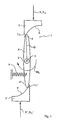
- gear device 1 consists of an output shaft 2, which can rotate about a rotation axis 3.
- Rotationally connected to the output shaft 2 are two diametrically arranged, straight lever 4, 4 ', which extend radially from the output shaft 2.
- the transmission device 1 further comprises two mutually opposite with respect to the axis of rotation 3 sliding elements 5, 5 ', whose axis of rotation 3 facing sides arcuate inclined surfaces 6, 6' form.
- Each inclined surface 6, 6 ' is at a point of action 7.1, 7.1 with a radially outer end 8, 8' of a lever 4, 4 'in effect. How out Fig.
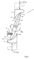
- the arcuate contour of the inclined surfaces 6, 6 ' is designed so that the inclination ⁇ during the displacement of the active site 7.2, 7.2' increases and in the position after Fig. 2 and 2a which assumes ⁇ 2 higher than ⁇ 1.
- a constant displacement force FV the normal force FN2 and the force FH2 acting on the end 8 of the lever 4 decrease.
- the torque M2 is lower, the rotational speed, however, increases.
- the transmission device thus generates at constant displacement force F v and constant displacement speed of the displacement elements 5, 5 about the rotation axis 3 a rotational movement with steadily decreasing torque M and increasing rotational speed.
- the initially high torque M1 can be used to overcome breakaway torques, the subsequently increasing rotational speed for rapid adjustment.
- the inclined surface 6 can also be polygonal-shaped, as in FIG Fig. 3 shown.
- a arranged at the end 8 of the lever 4 rolling elements 18 reduces the friction forces at the site of action. 7
- Fig. 4 In training after Fig. 4 is the sliding body 5 equipped with an arcuate gate 10 with an upper inclined surface 6.1 and an equidistant for this lower inclined surface 6.2.
- the scenery 10 runs one end of the lever 4 auskragender pin 11, which is supported at displacement of the displacement element 5 in the direction of rotation axis 3 at the action location 7.1 at the upper inclined surface 6.1, with opposite displacement, however, at the action location 7.2 on the lower inclined surface 6.2 ( please refer Fig. 4a, 4b ).
- a return spring 9 a transmission device acting in both directions of rotation can be created.
- Fig. 5 shows a transmission device 1, the three rigidly connected to each other, about the axis of rotation 3 together rotatable lever 4, 4 'and 4 ", each with an associated displacement element 5, 5' and 5" has.
- the transmission device 1 may have a plurality of further embodiments, in which the levers 4 are arranged, for example, asymmetrically to each other or in other numbers.
- the same effect is achieved directly on one of the levers 4 up to 4 "attacking handle (handle loop 19, train in direction Y).
- the transmission device 1 is in Fig. 6 shown, in which the generated torque M is used to release a locking adjuster 17 for a vehicle seat.
- the Rastversteller 17 consists of a first, fixedly connected to the seat part fitting part 12 and a second, arranged on the backrest fitting 13.
- the first fitting part 12 and the second fitting part 13 are about an axis 14, which simultaneously represents the pivot axis of the seat part and backrest , mutually rotatable.
- a on the second fitting part 13 in the region of the axis 3 rotatably arranged latching pawl 15th can optionally engage in one of the recessed in the outer periphery of the first fitting part 12 recesses 16, 16 'and thus fix the angular position of the backrest adjustable.
- the detent pawl 15 is rotatably mounted on the output shaft 2 of the transmission device 1 and can be dug out of this first with high release force, subsequently with high release speed of the recesses 16, 16 '.
Landscapes
- Engineering & Computer Science (AREA)
- Mechanical Engineering (AREA)
- General Engineering & Computer Science (AREA)
- Aviation & Aerospace Engineering (AREA)
- Transportation (AREA)
- Seats For Vehicles (AREA)
- Chairs For Special Purposes, Such As Reclining Chairs (AREA)
- Transmission Devices (AREA)
Description
- Die Erfindung betrifft eine Getriebevorrichtung, für einen Versteller eines Fahrzeugsitzes, zur Umwandlung einer linearen Antriebsbewegung in eine drehende Abtriebsbewegung, sowie einen damit ausgestatteten Rastversteller für einen Fahrzeugsitz.
- Eine gattungsgemäße Getriebeeinrichtung für die Neigungsverstellung der Rückenlehne eines Fahrzeugsitzes ist aus der Offenlegungsschrift
DE 30 01 164 A1 bekannt. Sie besteht aus einem einfachen Hebelwerk, mittels dessen die Bewegung eines linear arbeitenden Kolbens eines Hydraulikzylinders in eine Drehbewegung umgewandelt wird. Das Abtriebsdrehmoment ist dabei im Wesentlichen über den gesamten Weg des Kolbens konstant. - Derartige Getriebeeinrichtungen erfordern einen erheblichen Bauraum und sind insbesondere dann weniger geeignet, wenn im Verlaufe der Drehbewegung unterschiedlich hohe Drehmomente und Drehgeschwindigkeiten gefordert werden. Beim Lösen von rastend wirkenden Arretiereinrichtungen, insbesondere Rastverstellern von Fahrzeugsitzen, ist jedoch in der Regel ein hohes Lösemoment erforderlich, durch welches die rastenden Bauteile durch Drehung außer unmittelbarem Eingriff gebracht werden. Eine hohe Verstellgeschwindigkeit ist hierbei nicht notwendig. Nachdem dies erfolgt ist, sollen die Bauteile zügig in ihre Freigabe-Endstellung gebracht werden, wozu ein hohes Verstellmoment nicht mehr erforderlich ist.
- Eine Getriebevorrichtung für einen Fahrzeugsitz ist beispielsweise aus der
US-PS 3,999,247 bekannt. - Ein Rastversteller für einen Fahrzeugsitz ist beispielsweise auch aus der
US 3,051,526 A bekannt. - Ein Getriebe zur Umsetzung einer rotierenden Bewegung in eine reziproke Bewegung ist beispielsweise aus der
DE 591 878 C bekannt. - Der Erfindung liegt die Aufgabe zugrunde, eine kompakt bauende Getriebeeinrichtung zur Umwandlung einer linearen Antriebsbewegung in eine drehende Abtriebsbewegung bereitzustellen. Vorzugsweise sollen dabei Abtriebsmoment und -geschwindigkeit im Verlaufe der Bewegung auf einfache Weise veränderbar sein.
- Die Aufgabe wird erfindungsgemäß durch die Merkmale des Anspruchs 1 gelöst, Vorteilhafte Ausgestaltungen ergeben sich aus den Unteransprüchen.
- Durch den Kontakt mit der sich linear bewegenden Schrägfläche wird das zugeordnete Hebelende seitlich verlagert. Hierdurch führt der auf der Abtriebsachse gelagerte Hebel eine Schwenkbewegung aus, infolge derer die abtreibende Welle eine Drehbewegung ausführt. Die Schrägfläche ist dabei so ausgebildet, dass ihre Oberfläche am Wirkort zwischen Hebelende und Schrägfläche gegenüber ihrer Verschieberichtung geneigt ist, und zwar um einen Winkel zwischen 0° und 90°. Die durch die Keilwirkung auf das Hebelende ausgeübte, zur Verschieberichtung der Schrägfläche orthogonale und durch die Drehlagerung des Hebels in Rotation umgewandelte Kraft ist dabei um so größer, je kleiner der Neigungswinkel gewählt wird. Naturgemäß wird in diesem Fall bei kleiner Drehgeschwindigkeit ein hohes Drehmoment an der antreibende Welle erzeugt. Ist der Neigungswinkel hingegen größer, werden das erreichbare Drehmoment kleiner und die Drehgeschwindigkeit größer.
- Nach einer ersten bevorzugten Ausführungsform der Erfindung ist vorgesehen, dass die Wirkung zwischen Hebel und Schrägfläche gleitreibend erfolgt, insbesondere bei relativ geringen Wirkkräften. Hierdurch wird die Zahl der erforderlichen Bauteile besonders klein gehalten. Im Bereich des Wirkorts werden Hebel und/oder Schrägfläche vorzugsweise aus Werkstoffen mit geringen Reibkoeffizienten, beispielsweise Polyoxymethylen (POM) gefertigt.
- Alternativ kann vorgesehen werden, dass zwischen Hebel und Schrägfläche Rollreibung herrscht. Zu diesem Zweck kann beispielsweise eine am Hebelende gelagerte Rolle in Kontakt mit der Schrägfläche gebracht werden. Diese Ausführung bietet sich insbesondere bei sehr hohen Wirkkräften oder großer Neigung der Schrägfläche mit einer entsprechend zügigen Drehbewegung der abtreibenden Achse an.
- Mit Vorteil ist die Schrägfläche gegenüber einer gedachten, Wirkort und Abtriebsdrehachse verbindenden Geraden geneigt und wird in Richtung dieser gedachten Geraden oder hierzu parallel verschoben, wobei ein Hebel Verwendung finden kann, der sich genau in Richtung dieser gedachten Gerade erstreckt.
- Für viele Anwendungen, so auch zum Lösen von Fahrzeugsitz-Rastverstellern, nimmt die Neigung der Schrägfläche am Wirkort mit abnehmender Entfernung der Schrägfläche von der Abtriebsachse zu. Bei gleichförmiger Linearbewegung der Schrägfläche in Richtung der Drehachse vergrößert sich dabei die Drehgeschwindigkeit der abtreibenden Welle.
- Die Getriebeeinrichtung weist vorzugsweise eine Vielzahl jeweils mit einer gesonderten Schrägfläche in Wirkung stehende Hebel auf, wodurch das an der abtreibenden Welle erzeugbare Drehmoment in Abhängigkeit von der Zahl der Linearantriebe praktisch beliebig vergrößerbar ist. Ferner können sich bei einer entsprechenden Anordnung die durch die Wirkkräfte verursachten Lagerkräfte der abtreibenden Welle ausgleichen, so dass deren Lagerung vergleichsweise einfach ausgeführt werden kann.
- Dieser Vorteile tritt beispielsweise dann auf, wenn zwei einander vorzugsweise diametral angeordnete Hebel vorgesehen werden. Die Getriebevorrichtung kann hierdurch ferner ein besonders schlankes Gehäuse erhalten.
- Nach einer besonderen Ausbildung der Erfindung sind die Schrägflächen Teil einer in Richtung der Abtriebsdrehachse sowie entgegengerichtet bewegbaren Kulissenführung, so dass sowohl die Linearbewegung der Schrägfläche zur Drehachse hin als auch die entgegengesetzte Linearbewegung zur Erzeugung eines wechselnden Drehmoments nutzbar ist.
- Mit Vorteil sind derart ausgebildete Getriebevorrichtungen in Rastverstellern für Fahrzeugsitz verwendbar, insbesondere für die Neigungsverstellung der Rückenlehne, wobei der Abtrieb der Getriebeeinrichtung auf Rastklinke und/oder Sperrnocken des Rastverstellers wirkt. Zum Entriegeln der Rastklinke und/oder des die Rastklinke in Haltestellung sichernden Sperrnockens sind üblicherweise hohe Lösekräfte erforderlich. Ist der direkte Kontakt der Rastzähne hingegen einmal aufgehoben, sind Rastklinke und/oder Sperrnocken mit geringem Kraftaufwand, aber zügig, in die Entriegelungs-Endposition zu verlagern.
- Die Figuren stellen beispielhaft und schematisch verschiedene Ausführungen der Erfindung dar.
- Es zeigen:
- Fig. 1
- eine Vorrichtung nach einer ersten Ausführung der Erfindung in einer ersten Drehstellung,
- Fig. 1 a
- eine Bilanz der in Stellung nach
Fig. 1 wirkenden Kräfte, - Fig. 2
- die Vorrichtung nach
Fig. 2 in einer zweiten Drehstellung, - Fig. 2a
- die Kräftebilanz am Wirkort in der zweiten Drehstellung,
- Fig. 3
- eine andere erfindungsgemäße Getriebevorrichtung,
- Fig. 4
- eine Getriebevorrichtung nach einer weiteren Ausführung der Erfindung,
- Fig. 4a, b
- vergrößerte Darstellungen der Vorrichtung nach
Fig. 4 , - Fig. 5
- eine andere erfindungsgemäße Getriebevorrichtung,
- Fig. 6
- einen erfindungsgemäß ausgestatteten Rastversteller für einen Fahrzeugsitz.
- Die in den
Figuren 1 und2 gezeigte Getriebevorrichtung 1 besteht aus einer Abtriebswelle 2, welche um eine Drehachse 3 rotieren kann. Drehfest mit der Abtriebswelle 2 verbunden sind zwei diametral angeordnete, gerade Hebel 4, 4', welche sich radial von der Abtriebswelle 2 erstrecken. - Die Getriebevorrichtung 1 weist ferner zwei einander in Bezug auf die Drehachse 3 gegenüberliegende Verschiebeelemente 5, 5' auf, deren der Drehachse 3 zugewandte Seiten bogenförmige Schrägflächen 6, 6' ausbilden. Jede Schrägfläche 6, 6' steht an einem Wirkort 7.1, 7.1 mit einem radial äußeren Ende 8, 8' eines Hebels 4, 4' in Wirkung. Wie aus
Fig. 1 a ersichtlich, wird dabei auf das Ende 8 des Hebels 4 (und ebenso am gegenüberliegenden Ende 8') durch die von der Schrägfläche 6 in Verschieberichtung ausgeübten Kraft FV eine Normalkraft FN1 und infolge dessen eine Kraft FH1 herbeigeführt, die orthogonal zu einer Wirkort 7.1 und Drehachse 3 verbindenden Geraden G ausgerichtet ist und in Verbindung mit dem Hebel 4 das Drehmoment M1 erzeugt. Die Größe der Kraft FH1 hängt dabei von der Neigung α1 der durch den Wirkort 7.1 verlaufenden Tangente T1 ab. In der Drehstellung nachFig. 1 und1a ist die Neigung α1 der Tangente T1 relativ gering, so dass bei einer vorgegebenen Verschiebekraft F1 eine hohe Kraft FH1 und somit auch ein großes Drehmoment M1 an der Abtriebswelle 2 erzeugt werden. Die Drehgeschwindigkeit ist dabei naturgemäß gering. - Bei einer linearen Verlagerung der Verschiebeelemente 5, 5' in Richtung der Drehachse 3 wandert der Wirkort 7.2,7.2' lauf den Schrägflächen 6, 6`, wie in
Fig. 2 dargestellt. Die Richtungen X, X' der Verlagerungen müssen dabei nicht zwingend durch die Drehachse 3 hindurchführen, sondern können unter anderem auch, wie im Ausführungsbeispiel, zueinander parallel an der Drehachse vorbeilaufen. - Die bogenförmige Kontur der Schrägflächen 6, 6' ist so ausgelegt, dass die Neigung α während der Verlagerung des Wirkorts 7.2, 7.2' zunimmt und bei der Stellung nach
Fig. 2 und2a den gegenüber α1 höheren Wert α2 annimmt. Bei konstanter Verschiebekraft FV nehmen infolge dessen die Normalkraft FN2 und die auf das Ende 8 des Hebels 4 wirkende Kraft FH2 ab. Ebenso wird das Drehmoment M2 geringer, die Drehgeschwindigkeit nimmt hingegen zu. - Die Getriebevorrichtung erzeugt somit bei konstanter Verschiebekraft Fv und gleichbleibender Verschiebegeschwindigkeit der Verschiebeelemente 5, 5 um die Drehachse 3 eine Drehbewegung mit stetig sinkendem Drehmoment M und zunehmender Drehgeschwindigkeit. Das anfangs hohe Drehmoment M1 kann dabei zur Überwindung von Losbrechmomenten genutzt werden, die nachfolgend anwachsende Drehgeschwindigkeit zum zügigen Verstellen.
- Die Zurückstellung des Hebels 4 in seine Ausgangsposition wird bei sich nunmehr auseinander bewegenden Verschiebelementen 5, 5' durch eine Rückstellfeder 9 bewirkt, welche bei der vorherigen Drehbewegung vorgespannt wurde.
- Falls bei bestimmten Positionen der Getriebevorrichtung 1 sprunghafte Veränderungen von Drehmoment M und Drehgeschwindigkeit gewünscht werden, kann die Schrägfläche 6 auch polygonartig ausgebildet werden, wie in
Fig. 3 dargestellt. Ein am Ende 8 des Hebels 4 angeordneter Wälzkörper 18 reduziert dabei die Reibkräfte am Wirkort 7. - Bei der Ausbildung nach
Fig. 4 ist der Verschiebekörper 5 mit einer bogenförmigen Kulisse 10 mit einer oberen Schrägfläche 6.1 und einer hierzu äquidistanten unteren Schrägfläche 6.2 ausgestattet. In der Kulisse 10 läuft ein endseitig aus dem Hebel 4 auskragender Bolzen 11, der sich bei Verlagerung des Verschiebeelements 5 in Richtung der Drehachse 3 am Wirkort 7.1 an der oberen Schrägfläche 6.1, bei entgegengesetzter Verschiebung jedoch am Wirkort 7.2 an der unteren Schrägfläche 6.2 abstützt (sieheFig. 4a, 4b ). Somit kann ohne Verwendung einer Rückstellfeder 9 eine in beiden Drehrichtungen wirkende Getriebevorrichtung geschaffen werden. -
Fig. 5 zeigt eine Getriebevorrichtung 1, die drei miteinander starr verbundene, um die Drehachse 3 gemeinsam drehbare Hebel 4, 4' und 4" mit jeweils einem zugeordneten Verschiebeelement 5, 5' und 5" aufweist. Selbstverständlich kann die Getriebevorrichtung 1 eine Vielzahl weiterer Ausbildungen aufweisen, bei denen die Hebel 4 beispielsweise zueinander asymmetrisch oder in anderer Zahl angeordnet sind. Ferner ist es möglich, aus Sicherheitsgründen beispielsweise das Verschiebeelement 5" manuell betätigbar zu gestalten, so dass bei einem Ausfall elektrisch angetriebener Verschiebeelemente 5 und 5' eine Notbetätigung in Richtung des Moments M erfolgen kann. Die gleiche Wirkung erzielt eine unmittelbar an einem der Hebel 4 bis 4" angreifende Handhabe (Griffschlaufe 19, Zug in Richtung Y). Eine mögliche Verwendung der erfindungsgemäßen Getriebevorrichtung 1 ist inFig. 6 dargestellt, bei welcher das erzeugte Drehmoment M zum Lösen eines Rastverstellers 17 für einen Fahrzeugsitz eingesetzt wird. Der Rastversteller 17 besteht aus einem ersten, mit dem Sitzteil fest verbundenen Beschlagteil 12 und einem zweiten, an der Rückenlehne angeordneten Beschlagteil 13. Das erste Beschlagteil 12 und das zweite Beschlagteil 13 sind um eine Achse 14, die gleichzeitig die Schwenkachse von Sitzteil und Rückenlehne darstellt, zueinander drehbeweglich. Eine am zweiten Beschlagteil 13 im Bereich der Achse 3 drehbar angeordnete Rastklinke 15 kann wahlweise in eine der im Außenumfang des ersten Beschlagteils 12 eingelassenen Ausnehmungen 16, 16' eingreifen und damit die Winkelstellung der Rückenlehne einstellbar fixieren. Die Rastklinke 15 ist drehfest auf der Abtriebswelle 2 der Getriebevorrichtung 1 befestigt und kann von dieser zuerst mit hoher Lösekraft, nachfolgend mit hoher Lösegeschwindigkeit aus den Ausnehmungen 16, 16' ausgehoben werden. -
- 1
- Getriebevorrichtung
- 2
- Abtriebswelle
- 3
- Drehachse
- 4
- Hebel
- 5
- Verschiebeelement
- 6
- Schrägfläche
- 7
- Wirkort
- 8
- Ende (des Hebels 4)
- 9
- Rückstellfeder
- 10
- Kulisse
- 11
- Bolzen
- 12
- Beschlagteil (sitzteilseitig)
- 13
- Beschlagteil (rückenlehnenseitig)
- 14
- Achse
- 15
- Rastklinke
- 16
- Ausnehmung
- 17
- Rastversteller
- 18
- Wälzkörper
- 19
- Griffschlaufe
Claims (9)
- Getriebevorrichtung (1) für einen Versteller eines Fahrzeugsitzes, zur Umwandlung einer linearen Antriebsbewegung in eine drehende Abtriebsbewegung, gekennzeichnet durch mindestens einen mit der Abtriebsachse verbundenen, sich gegenüber dieser radial erstreckenden Hebel (4, 4'), dessen freies Ende mit einer linear in Richtung der Abtriebsachse bewegbaren Schrägfläche (6, 6') des Verschiebeelements (5, 5') in Wirkung steht, wobei die Schrägfläche (6, 6') bogen- oder polygonförmig ausgebildet ist.
- Getriebevorrichtung (1) nach Anspruch 1, dadurch gekennzeichnet, dass die Schrägfläche (6, 6') gegenüber einer gedachten, den jeweiligen Wirkort (7) und die Abtriebsdrehachse verbindenden Geraden G um einen Winkel α mit 0°<α<90° geneigt ist.
- Getriebevorrichtung (1) nach Anspruch 1 oder 2, dadurch gekennzeichnet, dass die Wirkung zwischen Hebel (4, 4') und Schrägfläche (6, 6') gleitreibend erfolgt.
- Getriebevorrichtung (1) nach Anspruch 1 oder 2, dadurch gekennzeichnet, dass die Wirkung zwischen Hebel (4, 4') und Schrägfläche (6, 6') rollreibend erfolgt.
- Getriebevorrichtung (1) nach Anspruch 1, dadurch gekennzeichnet, dass die Neigung α der Schrägfläche (6, 6') am Wirkort mit abnehmender Entfernung der Schrägfläche (6, 6') von der Abtriebsachse zunimmt.
- Getriebevorrichtung (1) nach einem der vorhergehenden Ansprüche, gekennzeichnet durch eine Vielzahl jeweils mit einer gesonderten Schrägfläche (6, 6') in Wirkung stehende Hebel (4, 4').
- Getriebevorrichtung (1) nach Anspruch 6, gekennzeichnet durch zwei einander vorzugsweise diametral gegenüberstehende Hebel (4, 4').
- Getriebevorrichtung (1) nach einem der vorhergehenden Ansprüche, dadurch gekennzeichnet, dass die Schrägflächen (6, 6') Teil einer in Richtung der Abtriebsdrehachse sowie entgegengerichtet bewegbaren Kulissenführung sind.
- Rastversteller für Fahrzeugsitz, insbesondere für die Neigungsverstellung der Rückenlehne, mit einer auf Rastklinke und/oder Sperrnocken wirkenden Getriebevorrichtung (1) nach einem der vorhergehenden Ansprüche.
Priority Applications (1)
| Application Number | Priority Date | Filing Date | Title |
|---|---|---|---|
| PL05779467T PL1784314T3 (pl) | 2004-08-07 | 2005-08-01 | Urządzenie napędowe, zwłaszcza do przestawiania siedzenia pojazdu mechanicznego i układ przestawiania zapadkowego dla siedzenia pojazdu |
Applications Claiming Priority (2)
| Application Number | Priority Date | Filing Date | Title |
|---|---|---|---|
| DE102004038457A DE102004038457C5 (de) | 2004-08-07 | 2004-08-07 | Getriebevorrichtung, insbesondere für einen Sitzversteller eines Kraftfahrzeugs, und Rastversteller für einen Fahrzeugsitz |
| PCT/EP2005/008308 WO2006015755A2 (de) | 2004-08-07 | 2005-08-01 | Getriebevorrichtung insbesondere für einen sitzversteller eines kraftfahrzeugs und rastversteller für einen fahrzeugsitz |
Publications (2)
| Publication Number | Publication Date |
|---|---|
| EP1784314A2 EP1784314A2 (de) | 2007-05-16 |
| EP1784314B1 true EP1784314B1 (de) | 2011-11-16 |
Family
ID=35539413
Family Applications (1)
| Application Number | Title | Priority Date | Filing Date |
|---|---|---|---|
| EP05779467A Expired - Lifetime EP1784314B1 (de) | 2004-08-07 | 2005-08-01 | Getriebevorrichtung insbesondere für einen sitzversteller eines kraftfahrzeugs und rastversteller für einen fahrzeugsitz |
Country Status (7)
| Country | Link |
|---|---|
| US (1) | US8166839B2 (de) |
| EP (1) | EP1784314B1 (de) |
| JP (1) | JP5046934B2 (de) |
| AT (1) | ATE533663T1 (de) |
| DE (1) | DE102004038457C5 (de) |
| PL (1) | PL1784314T3 (de) |
| WO (1) | WO2006015755A2 (de) |
Families Citing this family (1)
| Publication number | Priority date | Publication date | Assignee | Title |
|---|---|---|---|---|
| ITCO20120018A1 (it) * | 2012-04-16 | 2013-10-17 | Giulio Manzoni | Cinematismo con moto frenato ed autobloccaggio per supporti di piani ribaltabili. |
Family Cites Families (25)
| Publication number | Priority date | Publication date | Assignee | Title |
|---|---|---|---|---|
| DE591878C (de) | 1930-04-19 | 1934-01-29 | Raymond A Walter | Erzeugung einer Hinundherbewegung durch zwei mit je einem Zapfen in eine Kurbelschleife eingreifende Raeder |
| NL104567C (de) * | 1958-11-08 | 1900-01-01 | ||
| US3444949A (en) * | 1967-07-28 | 1969-05-20 | Gen Motors Corp | Safety latch for hinged seat back |
| US3753386A (en) * | 1971-03-03 | 1973-08-21 | F Scott | Valve actuator |
| US3999247A (en) * | 1974-12-31 | 1976-12-28 | Cremer Heinz P | Vehicle seat fitting |
| DE3001164A1 (de) * | 1980-01-15 | 1981-07-16 | Audi Nsu Auto Union Ag, 7107 Neckarsulm | Vorrichtung zum verstellen einer sitzlehne |
| US4339960A (en) * | 1980-06-30 | 1982-07-20 | Sunpower, Inc. | Drive mechanism for Stirling engine displacer and piston and other reciprocating bodies |
| DE3027629C2 (de) * | 1980-07-21 | 1987-02-12 | P.A. Rentrop, Hubbert & Wagner Fahrzeugausstattungen Gmbh & Co Kg, 3060 Stadthagen | Gelenkbeschlag für einen Sitz mit verstellbarer Rückenlehne, insbesondere Kraftfahrzeugsitz |
| DE3231352C1 (de) * | 1982-08-24 | 1983-11-24 | Festo-Maschinenfabrik Gottlieb Stoll, 7300 Esslingen | Vorrichtung zur Umwandlung einer geradlinigen Bewegung in eine Drehbewegung |
| JPS63111359A (ja) * | 1986-10-25 | 1988-05-16 | Taiyo Yuden Co Ltd | カム装置 |
| SE462811B (sv) * | 1989-05-09 | 1990-09-03 | Hans Karlsson | Anordning foer omvandling av en fram- och aatergaaende roerelse till en roterande roerelse |
| JPH03244856A (ja) * | 1990-02-23 | 1991-10-31 | Sharp Corp | カム機構 |
| JPH0418408A (ja) | 1990-11-30 | 1992-01-22 | Mitsui Toatsu Chem Inc | 熱硬化性樹脂組成物 |
| DE4227266A1 (de) * | 1992-08-18 | 1993-05-27 | Anton Schad | Kurbelschleifenantriebsgetriebe zur umwandlung einer hin-und hergehenden bewegung in eine drehbewegung oder umgekehrt |
| WO1995005551A1 (en) * | 1993-08-17 | 1995-02-23 | Anton Schad | Slider-crank driving mechanism for the transformation of a reciprocating motion into rotation or vice versa |
| JPH0893874A (ja) * | 1994-09-26 | 1996-04-12 | Mitsuhashi Seisakusho:Kk | 一動作往復揺動カム装置 |
| JP3468345B2 (ja) * | 1998-01-09 | 2003-11-17 | 日産車体株式会社 | シート装置 |
| DE19845698A1 (de) * | 1998-10-05 | 2000-04-13 | Faure Bertrand Sitztech Gmbh | Feststellvorrichtung für Verstellbeschläge an Fahrzeugsitzen |
| US6367342B1 (en) * | 2000-02-11 | 2002-04-09 | Christopher A. Weismann | Indexing drive and transmission |
| US6945131B2 (en) * | 2000-09-21 | 2005-09-20 | Cimosys Limited | Furniture drive embodied as a double drive |
| JP4596621B2 (ja) * | 2000-09-22 | 2010-12-08 | 三陽機器株式会社 | カム装置を備えた動力伝達自動遮断装置、及びこの動力伝達自動遮断装置を備えた走行体 |
| JP4018408B2 (ja) | 2002-02-01 | 2007-12-05 | 徳厚 小島 | 耐火二層管 |
| JP4048789B2 (ja) * | 2002-02-06 | 2008-02-20 | マツダ株式会社 | 車両のシート格納構造 |
| JP3860484B2 (ja) | 2002-02-15 | 2006-12-20 | 株式会社東芝 | 電源管理装置 |
| DE10312140B4 (de) * | 2003-03-19 | 2006-10-05 | Johnson Controls Gmbh | Feststell- und Neigungsverstellvorrichtung für Beschläge |
-
2004
- 2004-08-07 DE DE102004038457A patent/DE102004038457C5/de not_active Expired - Fee Related
-
2005
- 2005-08-01 JP JP2007525219A patent/JP5046934B2/ja not_active Expired - Fee Related
- 2005-08-01 AT AT05779467T patent/ATE533663T1/de active
- 2005-08-01 US US11/659,561 patent/US8166839B2/en not_active Expired - Fee Related
- 2005-08-01 EP EP05779467A patent/EP1784314B1/de not_active Expired - Lifetime
- 2005-08-01 PL PL05779467T patent/PL1784314T3/pl unknown
- 2005-08-01 WO PCT/EP2005/008308 patent/WO2006015755A2/de not_active Ceased
Also Published As
| Publication number | Publication date |
|---|---|
| WO2006015755A2 (de) | 2006-02-16 |
| US8166839B2 (en) | 2012-05-01 |
| DE102004038457B4 (de) | 2006-11-09 |
| EP1784314A2 (de) | 2007-05-16 |
| ATE533663T1 (de) | 2011-12-15 |
| WO2006015755A3 (de) | 2007-04-05 |
| JP5046934B2 (ja) | 2012-10-10 |
| PL1784314T3 (pl) | 2012-04-30 |
| US20080197685A1 (en) | 2008-08-21 |
| JP2008509364A (ja) | 2008-03-27 |
| DE102004038457A1 (de) | 2006-03-16 |
| DE102004038457C5 (de) | 2008-07-24 |
Similar Documents
| Publication | Publication Date | Title |
|---|---|---|
| DE69700026T2 (de) | Höhenverstellvorrichtung für einen Fahrzeugsitz | |
| EP0981696B1 (de) | Exzenterzahnradgetriebe | |
| DE102010062414B4 (de) | Taumelgelenkbeschlag für eine Verstellvorrichtung eines Kraftfahrzeugsitzes, insbesondere für einen Rückenlehnengelenkbeschlag | |
| EP3472497B1 (de) | Parksperre für ein kraftfahrzeug | |
| WO2005090826A1 (de) | Exzentergetriebe | |
| DE69303178T2 (de) | Bremsmotor mit geringen abmessungen | |
| DE102023115292A1 (de) | Aktor zur Bereitstellung eines Drehmoments mit einem Linearantrieb | |
| DE102016207827A1 (de) | Betätigungseinheit mit einer Kurvenscheibe zum Bereitstellen einer nichtlinearen Kraft für ein Automatikgetriebe sowie Aktor mit Betätigungseinheit | |
| DE10009375C2 (de) | Türscharnier mit integriertem Türfeststeller | |
| EP1128979B1 (de) | Sitzhöheneinsteller-antrieb für einen fahrzeugsitz | |
| DE19907483C2 (de) | Beidseitig wirkende Verstellvorrichtung | |
| WO2000037819A1 (de) | Getriebeähnlich ausgebildete vorrichtung zur betätigung der bremsbacken | |
| WO2022083982A1 (de) | Exzentergetriebe für einen bremskrafterzeuger, bremskrafterzeuger | |
| DE102004038457B4 (de) | Getriebevorrichtung, insbesondere für einen Sitzversteller eines Kraftfahrzeugs, und Rastversteller für einen Fahrzeugsitz | |
| DE102013101572A1 (de) | Verstellvorrichtung | |
| DE102019111222A1 (de) | Luftleitvorrichtung mit Bremseinrichtung | |
| EP0908349A2 (de) | Verstellmechanik für eine Stufenlose Dreh-Verstellung eines Abtriebs-Wirkteiles | |
| DE102020101117A1 (de) | Parksperrenvorrichtung und Betätigungseinheit für eine Parksperrenvorrichtung | |
| DE19744726A1 (de) | Verstellmechanik für eine selbsthemmende Dreh-Verstellung eines Abtriebs-Wirkteiles | |
| DE102013221349A1 (de) | Antriebseinheit | |
| DE19631228C2 (de) | Federnd ausgebildetes Axiallager für eine Getriebewelle einer Kraftfahrzeugsitzverstelleinrichtung | |
| EP3280609B1 (de) | Längseinsteller für einen fahrzeugsitz | |
| EP1472121B1 (de) | Arretierbare spannvorrichtung, insbesondere für eine feststellbremsanlage | |
| DE10129271A1 (de) | Sitzverstellgetriebe | |
| DE2843572A1 (de) | Vorrichtung zur uebertragung einer bewegung zwischen einer welle und einem drehelement |
Legal Events
| Date | Code | Title | Description |
|---|---|---|---|
| PUAI | Public reference made under article 153(3) epc to a published international application that has entered the european phase |
Free format text: ORIGINAL CODE: 0009012 |
|
| AK | Designated contracting states |
Kind code of ref document: A2 Designated state(s): AT BE BG CH CY CZ DE DK EE ES FI FR GB GR HU IE IS IT LI LT LU LV MC NL PL PT RO SE SI SK TR |
|
| AX | Request for extension of the european patent |
Extension state: AL BA HR MK YU |
|
| R17D | Deferred search report published (corrected) |
Effective date: 20070405 |
|
| DAX | Request for extension of the european patent (deleted) | ||
| 17P | Request for examination filed |
Effective date: 20071005 |
|
| RBV | Designated contracting states (corrected) |
Designated state(s): AT BE BG CH CY CZ DE DK EE ES FI FR GB GR HU IE IS IT LI LT LU LV MC NL PL PT RO SE SI SK TR |
|
| REG | Reference to a national code |
Ref country code: DE Ref legal event code: 8566 |
|
| 17Q | First examination report despatched |
Effective date: 20080320 |
|
| GRAP | Despatch of communication of intention to grant a patent |
Free format text: ORIGINAL CODE: EPIDOSNIGR1 |
|
| GRAS | Grant fee paid |
Free format text: ORIGINAL CODE: EPIDOSNIGR3 |
|
| GRAA | (expected) grant |
Free format text: ORIGINAL CODE: 0009210 |
|
| AK | Designated contracting states |
Kind code of ref document: B1 Designated state(s): AT BE BG CH CY CZ DE DK EE ES FI FR GB GR HU IE IS IT LI LT LU LV MC NL PL PT RO SE SI SK TR |
|
| REG | Reference to a national code |
Ref country code: GB Ref legal event code: FG4D Free format text: NOT ENGLISH |
|
| REG | Reference to a national code |
Ref country code: CH Ref legal event code: EP |
|
| REG | Reference to a national code |
Ref country code: DE Ref legal event code: R081 Ref document number: 502005012146 Country of ref document: DE Owner name: ADIENT LUXEMBOURG HOLDING S.A.R.L., LU Free format text: FORMER OWNER: JOHNSON CONTROLS GMBH, 51399 BURSCHEID, DE Ref country code: DE Ref legal event code: R081 Ref document number: 502005012146 Country of ref document: DE Owner name: ADIENT LUXEMBOURG HOLDING S.A R.L., LU Free format text: FORMER OWNER: JOHNSON CONTROLS GMBH, 51399 BURSCHEID, DE |
|
| REG | Reference to a national code |
Ref country code: IE Ref legal event code: FG4D Free format text: LANGUAGE OF EP DOCUMENT: GERMAN |
|
| REG | Reference to a national code |
Ref country code: DE Ref legal event code: R096 Ref document number: 502005012146 Country of ref document: DE Effective date: 20120126 |
|
| REG | Reference to a national code |
Ref country code: NL Ref legal event code: VDEP Effective date: 20111116 |
|
| LTIE | Lt: invalidation of european patent or patent extension |
Effective date: 20111116 |
|
| PG25 | Lapsed in a contracting state [announced via postgrant information from national office to epo] |
Ref country code: LT Free format text: LAPSE BECAUSE OF FAILURE TO SUBMIT A TRANSLATION OF THE DESCRIPTION OR TO PAY THE FEE WITHIN THE PRESCRIBED TIME-LIMIT Effective date: 20111116 Ref country code: IS Free format text: LAPSE BECAUSE OF FAILURE TO SUBMIT A TRANSLATION OF THE DESCRIPTION OR TO PAY THE FEE WITHIN THE PRESCRIBED TIME-LIMIT Effective date: 20120316 |
|
| REG | Reference to a national code |
Ref country code: PL Ref legal event code: T3 |
|
| REG | Reference to a national code |
Ref country code: SK Ref legal event code: T3 Ref document number: E 11049 Country of ref document: SK |
|
| PG25 | Lapsed in a contracting state [announced via postgrant information from national office to epo] |
Ref country code: NL Free format text: LAPSE BECAUSE OF FAILURE TO SUBMIT A TRANSLATION OF THE DESCRIPTION OR TO PAY THE FEE WITHIN THE PRESCRIBED TIME-LIMIT Effective date: 20111116 Ref country code: SE Free format text: LAPSE BECAUSE OF FAILURE TO SUBMIT A TRANSLATION OF THE DESCRIPTION OR TO PAY THE FEE WITHIN THE PRESCRIBED TIME-LIMIT Effective date: 20111116 Ref country code: GR Free format text: LAPSE BECAUSE OF FAILURE TO SUBMIT A TRANSLATION OF THE DESCRIPTION OR TO PAY THE FEE WITHIN THE PRESCRIBED TIME-LIMIT Effective date: 20120217 Ref country code: SI Free format text: LAPSE BECAUSE OF FAILURE TO SUBMIT A TRANSLATION OF THE DESCRIPTION OR TO PAY THE FEE WITHIN THE PRESCRIBED TIME-LIMIT Effective date: 20111116 Ref country code: LV Free format text: LAPSE BECAUSE OF FAILURE TO SUBMIT A TRANSLATION OF THE DESCRIPTION OR TO PAY THE FEE WITHIN THE PRESCRIBED TIME-LIMIT Effective date: 20111116 Ref country code: PT Free format text: LAPSE BECAUSE OF FAILURE TO SUBMIT A TRANSLATION OF THE DESCRIPTION OR TO PAY THE FEE WITHIN THE PRESCRIBED TIME-LIMIT Effective date: 20120316 |
|
| REG | Reference to a national code |
Ref country code: IE Ref legal event code: FD4D |
|
| PG25 | Lapsed in a contracting state [announced via postgrant information from national office to epo] |
Ref country code: CY Free format text: LAPSE BECAUSE OF FAILURE TO SUBMIT A TRANSLATION OF THE DESCRIPTION OR TO PAY THE FEE WITHIN THE PRESCRIBED TIME-LIMIT Effective date: 20111116 |
|
| PG25 | Lapsed in a contracting state [announced via postgrant information from national office to epo] |
Ref country code: EE Free format text: LAPSE BECAUSE OF FAILURE TO SUBMIT A TRANSLATION OF THE DESCRIPTION OR TO PAY THE FEE WITHIN THE PRESCRIBED TIME-LIMIT Effective date: 20111116 Ref country code: DK Free format text: LAPSE BECAUSE OF FAILURE TO SUBMIT A TRANSLATION OF THE DESCRIPTION OR TO PAY THE FEE WITHIN THE PRESCRIBED TIME-LIMIT Effective date: 20111116 Ref country code: BG Free format text: LAPSE BECAUSE OF FAILURE TO SUBMIT A TRANSLATION OF THE DESCRIPTION OR TO PAY THE FEE WITHIN THE PRESCRIBED TIME-LIMIT Effective date: 20120216 Ref country code: IE Free format text: LAPSE BECAUSE OF FAILURE TO SUBMIT A TRANSLATION OF THE DESCRIPTION OR TO PAY THE FEE WITHIN THE PRESCRIBED TIME-LIMIT Effective date: 20111116 |
|
| PG25 | Lapsed in a contracting state [announced via postgrant information from national office to epo] |
Ref country code: RO Free format text: LAPSE BECAUSE OF FAILURE TO SUBMIT A TRANSLATION OF THE DESCRIPTION OR TO PAY THE FEE WITHIN THE PRESCRIBED TIME-LIMIT Effective date: 20111116 Ref country code: IT Free format text: LAPSE BECAUSE OF FAILURE TO SUBMIT A TRANSLATION OF THE DESCRIPTION OR TO PAY THE FEE WITHIN THE PRESCRIBED TIME-LIMIT Effective date: 20111116 |
|
| PLBE | No opposition filed within time limit |
Free format text: ORIGINAL CODE: 0009261 |
|
| STAA | Information on the status of an ep patent application or granted ep patent |
Free format text: STATUS: NO OPPOSITION FILED WITHIN TIME LIMIT |
|
| 26N | No opposition filed |
Effective date: 20120817 |
|
| REG | Reference to a national code |
Ref country code: DE Ref legal event code: R097 Ref document number: 502005012146 Country of ref document: DE Effective date: 20120817 |
|
| BERE | Be: lapsed |
Owner name: JOHNSON CONTROLS G.M.B.H. Effective date: 20120831 |
|
| REG | Reference to a national code |
Ref country code: CH Ref legal event code: PL |
|
| PG25 | Lapsed in a contracting state [announced via postgrant information from national office to epo] |
Ref country code: MC Free format text: LAPSE BECAUSE OF NON-PAYMENT OF DUE FEES Effective date: 20120831 |
|
| GBPC | Gb: european patent ceased through non-payment of renewal fee |
Effective date: 20120801 |
|
| PG25 | Lapsed in a contracting state [announced via postgrant information from national office to epo] |
Ref country code: CH Free format text: LAPSE BECAUSE OF NON-PAYMENT OF DUE FEES Effective date: 20120831 Ref country code: LI Free format text: LAPSE BECAUSE OF NON-PAYMENT OF DUE FEES Effective date: 20120831 Ref country code: ES Free format text: LAPSE BECAUSE OF FAILURE TO SUBMIT A TRANSLATION OF THE DESCRIPTION OR TO PAY THE FEE WITHIN THE PRESCRIBED TIME-LIMIT Effective date: 20120227 |
|
| PG25 | Lapsed in a contracting state [announced via postgrant information from national office to epo] |
Ref country code: BE Free format text: LAPSE BECAUSE OF NON-PAYMENT OF DUE FEES Effective date: 20120831 |
|
| PG25 | Lapsed in a contracting state [announced via postgrant information from national office to epo] |
Ref country code: FI Free format text: LAPSE BECAUSE OF FAILURE TO SUBMIT A TRANSLATION OF THE DESCRIPTION OR TO PAY THE FEE WITHIN THE PRESCRIBED TIME-LIMIT Effective date: 20111116 |
|
| PG25 | Lapsed in a contracting state [announced via postgrant information from national office to epo] |
Ref country code: GB Free format text: LAPSE BECAUSE OF NON-PAYMENT OF DUE FEES Effective date: 20120801 |
|
| REG | Reference to a national code |
Ref country code: AT Ref legal event code: MM01 Ref document number: 533663 Country of ref document: AT Kind code of ref document: T Effective date: 20120831 |
|
| PG25 | Lapsed in a contracting state [announced via postgrant information from national office to epo] |
Ref country code: AT Free format text: LAPSE BECAUSE OF NON-PAYMENT OF DUE FEES Effective date: 20120831 |
|
| PG25 | Lapsed in a contracting state [announced via postgrant information from national office to epo] |
Ref country code: TR Free format text: LAPSE BECAUSE OF FAILURE TO SUBMIT A TRANSLATION OF THE DESCRIPTION OR TO PAY THE FEE WITHIN THE PRESCRIBED TIME-LIMIT Effective date: 20111116 |
|
| PG25 | Lapsed in a contracting state [announced via postgrant information from national office to epo] |
Ref country code: LU Free format text: LAPSE BECAUSE OF NON-PAYMENT OF DUE FEES Effective date: 20120801 |
|
| REG | Reference to a national code |
Ref country code: DE Ref legal event code: R082 Ref document number: 502005012146 Country of ref document: DE Representative=s name: KIERDORF RITSCHEL PATENTANWAELTE PARTG MBB, DE |
|
| PG25 | Lapsed in a contracting state [announced via postgrant information from national office to epo] |
Ref country code: HU Free format text: LAPSE BECAUSE OF FAILURE TO SUBMIT A TRANSLATION OF THE DESCRIPTION OR TO PAY THE FEE WITHIN THE PRESCRIBED TIME-LIMIT Effective date: 20050801 |
|
| REG | Reference to a national code |
Ref country code: FR Ref legal event code: PLFP Year of fee payment: 11 |
|
| REG | Reference to a national code |
Ref country code: DE Ref legal event code: R082 Ref document number: 502005012146 Country of ref document: DE |
|
| REG | Reference to a national code |
Ref country code: FR Ref legal event code: PLFP Year of fee payment: 12 |
|
| REG | Reference to a national code |
Ref country code: DE Ref legal event code: R081 Ref document number: 502005012146 Country of ref document: DE Owner name: ADIENT LUXEMBOURG HOLDING S.A.R.L., LU Free format text: FORMER OWNER: JOHNSON CONTROLS GMBH, 51399 BURSCHEID, DE Ref country code: DE Ref legal event code: R081 Ref document number: 502005012146 Country of ref document: DE Owner name: ADIENT LUXEMBOURG HOLDING S.A R.L., LU Free format text: FORMER OWNER: JOHNSON CONTROLS GMBH, 51399 BURSCHEID, DE |
|
| REG | Reference to a national code |
Ref country code: FR Ref legal event code: PLFP Year of fee payment: 13 |
|
| PGFP | Annual fee paid to national office [announced via postgrant information from national office to epo] |
Ref country code: DE Payment date: 20170831 Year of fee payment: 13 Ref country code: FR Payment date: 20170822 Year of fee payment: 13 Ref country code: SK Payment date: 20170731 Year of fee payment: 13 Ref country code: CZ Payment date: 20170728 Year of fee payment: 13 |
|
| PGFP | Annual fee paid to national office [announced via postgrant information from national office to epo] |
Ref country code: PL Payment date: 20170724 Year of fee payment: 13 |
|
| REG | Reference to a national code |
Ref country code: DE Ref legal event code: R081 Ref document number: 502005012146 Country of ref document: DE Owner name: ADIENT LUXEMBOURG HOLDING S.A R.L., LU Free format text: FORMER OWNER: ADIENT LUXEMBOURG HOLDING S.A.R.L., LUXEMBOURG, LU |
|
| REG | Reference to a national code |
Ref country code: DE Ref legal event code: R119 Ref document number: 502005012146 Country of ref document: DE |
|
| PG25 | Lapsed in a contracting state [announced via postgrant information from national office to epo] |
Ref country code: CZ Free format text: LAPSE BECAUSE OF NON-PAYMENT OF DUE FEES Effective date: 20180801 |
|
| REG | Reference to a national code |
Ref country code: SK Ref legal event code: MM4A Ref document number: E 11049 Country of ref document: SK Effective date: 20180801 |
|
| PG25 | Lapsed in a contracting state [announced via postgrant information from national office to epo] |
Ref country code: SK Free format text: LAPSE BECAUSE OF NON-PAYMENT OF DUE FEES Effective date: 20180801 |
|
| PG25 | Lapsed in a contracting state [announced via postgrant information from national office to epo] |
Ref country code: DE Free format text: LAPSE BECAUSE OF NON-PAYMENT OF DUE FEES Effective date: 20190301 |
|
| PG25 | Lapsed in a contracting state [announced via postgrant information from national office to epo] |
Ref country code: FR Free format text: LAPSE BECAUSE OF NON-PAYMENT OF DUE FEES Effective date: 20180831 |
|
| PG25 | Lapsed in a contracting state [announced via postgrant information from national office to epo] |
Ref country code: PL Free format text: LAPSE BECAUSE OF NON-PAYMENT OF DUE FEES Effective date: 20180801 |