EP1783293A2 - Bewehrter Dämmkörper für eine wärmegedämmte Fertigteilwand und Fertigteilwand sowie Verfahren zur Herstellung - Google Patents
Bewehrter Dämmkörper für eine wärmegedämmte Fertigteilwand und Fertigteilwand sowie Verfahren zur Herstellung Download PDFInfo
- Publication number
- EP1783293A2 EP1783293A2 EP06015305A EP06015305A EP1783293A2 EP 1783293 A2 EP1783293 A2 EP 1783293A2 EP 06015305 A EP06015305 A EP 06015305A EP 06015305 A EP06015305 A EP 06015305A EP 1783293 A2 EP1783293 A2 EP 1783293A2
- Authority
- EP
- European Patent Office
- Prior art keywords
- insulating body
- insulation board
- fixing elements
- reinforced
- reinforced insulating
- Prior art date
- Legal status (The legal status is an assumption and is not a legal conclusion. Google has not performed a legal analysis and makes no representation as to the accuracy of the status listed.)
- Granted
Links
Images

Classifications
-
- B—PERFORMING OPERATIONS; TRANSPORTING
- B28—WORKING CEMENT, CLAY, OR STONE
- B28B—SHAPING CLAY OR OTHER CERAMIC COMPOSITIONS; SHAPING SLAG; SHAPING MIXTURES CONTAINING CEMENTITIOUS MATERIAL, e.g. PLASTER
- B28B23/00—Arrangements specially adapted for the production of shaped articles with elements wholly or partly embedded in the moulding material; Production of reinforced objects
- B28B23/02—Arrangements specially adapted for the production of shaped articles with elements wholly or partly embedded in the moulding material; Production of reinforced objects wherein the elements are reinforcing members
- B28B23/028—Arrangements specially adapted for the production of shaped articles with elements wholly or partly embedded in the moulding material; Production of reinforced objects wherein the elements are reinforcing members for double - wall articles
-
- E—FIXED CONSTRUCTIONS
- E04—BUILDING
- E04B—GENERAL BUILDING CONSTRUCTIONS; WALLS, e.g. PARTITIONS; ROOFS; FLOORS; CEILINGS; INSULATION OR OTHER PROTECTION OF BUILDINGS
- E04B1/00—Constructions in general; Structures which are not restricted either to walls, e.g. partitions, or floors or ceilings or roofs
- E04B1/62—Insulation or other protection; Elements or use of specified material therefor
- E04B1/74—Heat, sound or noise insulation, absorption, or reflection; Other building methods affording favourable thermal or acoustical conditions, e.g. accumulating of heat within walls
- E04B1/76—Heat, sound or noise insulation, absorption, or reflection; Other building methods affording favourable thermal or acoustical conditions, e.g. accumulating of heat within walls specifically with respect to heat only
- E04B1/78—Heat insulating elements
- E04B1/80—Heat insulating elements slab-shaped
-
- E—FIXED CONSTRUCTIONS
- E04—BUILDING
- E04C—STRUCTURAL ELEMENTS; BUILDING MATERIALS
- E04C2/00—Building elements of relatively thin form for the construction of parts of buildings, e.g. sheet materials, slabs, or panels
- E04C2/02—Building elements of relatively thin form for the construction of parts of buildings, e.g. sheet materials, slabs, or panels characterised by specified materials
- E04C2/04—Building elements of relatively thin form for the construction of parts of buildings, e.g. sheet materials, slabs, or panels characterised by specified materials of concrete or other stone-like material; of asbestos cement; of cement and other mineral fibres
- E04C2/049—Building elements of relatively thin form for the construction of parts of buildings, e.g. sheet materials, slabs, or panels characterised by specified materials of concrete or other stone-like material; of asbestos cement; of cement and other mineral fibres completely or partially of insulating material, e.g. cellular concrete or foamed plaster
-
- E—FIXED CONSTRUCTIONS
- E04—BUILDING
- E04C—STRUCTURAL ELEMENTS; BUILDING MATERIALS
- E04C2/00—Building elements of relatively thin form for the construction of parts of buildings, e.g. sheet materials, slabs, or panels
- E04C2/02—Building elements of relatively thin form for the construction of parts of buildings, e.g. sheet materials, slabs, or panels characterised by specified materials
- E04C2/26—Building elements of relatively thin form for the construction of parts of buildings, e.g. sheet materials, slabs, or panels characterised by specified materials composed of materials covered by two or more of groups E04C2/04, E04C2/08, E04C2/10 or of materials covered by one of these groups with a material not specified in one of the groups
- E04C2/284—Building elements of relatively thin form for the construction of parts of buildings, e.g. sheet materials, slabs, or panels characterised by specified materials composed of materials covered by two or more of groups E04C2/04, E04C2/08, E04C2/10 or of materials covered by one of these groups with a material not specified in one of the groups at least one of the materials being insulating
- E04C2/288—Building elements of relatively thin form for the construction of parts of buildings, e.g. sheet materials, slabs, or panels characterised by specified materials composed of materials covered by two or more of groups E04C2/04, E04C2/08, E04C2/10 or of materials covered by one of these groups with a material not specified in one of the groups at least one of the materials being insulating composed of insulating material and concrete, stone or stone-like material
Definitions
- the present invention relates to a reinforced insulating body for a thermally insulated prefabricated concrete wall and insulation. It also relates to a manufactured with the insulating body prefabricated wall and a method for their preparation.
- Thermally insulated precast walls are well known. They come in different versions, on the one hand as one-sided insulated prefabricated walls (thermal insulation composite wall), which must be poured on the site, or already finished in the factory, one-sided insulated prefabricated walls, in which the thermal insulation in the form of thermal insulation panels on the lying Concrete pressed and connected during curing with this. Furthermore, there are the so-called sandwich walls, both sides of the insulating material, usually in the form of insulation boards, both sides have a concrete shell. The wall thicknesses of these concrete shells are usually different strength according to their function as an outer wall or as an inner wall. In particular, the production of sandwich prefabricated walls is complex, and their size is limited due to the transport dimension to the site. Usually, these walls are produced horizontally by first drying a concrete layer with the pressed-in insulation boards and then turned in a second concrete layer is pressed. This production is time consuming and labor intensive.
- the present invention is therefore based on the object to propose a possibility in which the production of a thermal insulation composite wall or sandwich wall is simplified and which also allows to make insulated prefabricated walls easy to finish on the construction site.
- the reinforced insulating body has at least one insulating board, on which at least one side spaced apart and perpendicular to the flat side of the insulating board arranged fixing elements are attached.
- the fixing elements extend substantially over the entire width of the flat side and may have the usual lattice girder profile. It is important that these fixing elements are stably fixed to the insulation board to fix this insulation board later during concreting.
- the reinforced insulating body has at least one reinforcing mat arranged on the fixing elements remote from the insulating board.
- the reinforced insulating body still has spacers on the ends of the fixing elements remote from the insulating panels and / or on the side of the reinforcing mat facing away from the insulating panels so as to make a distance from the outer surface of the later concrete wall.
- the reinforced insulating body has, according to another embodiment, fixing elements with a support plate, which bear against the insulation board.
- the support plate in the direction of insulation board facing engagement edges for engagement with corresponding grooves in the insulation board.
- the fixing bodies are glued to the insulation board. This allows easy and quick creation of the insulating body.
- stabilizing elements When using a reinforced DämmMechs in a sandwich panel with both sides of the insulation board arranged fixing projecting from the insulation board on both sides stabilization elements that prevent unwanted movements in the precast wall.
- These stabilizing elements are known plate-shaped, made of metal or plastic or carbon fiber bearing anchors, cylindrical torsion anchors and U-shaped composite needles.
- the reinforced insulating body as a whole unit is movable and transportable, so that it can also be used on the construction site between vertically arranged formwork panels.
- the reinforced insulating body can be manufactured in the factory or on the construction site and / or further processed. It can be used either in an existing battery formwork or in a formwork wall composed of individual formwork parts, with vertically arranged formwork intermediate spaces, standing. This can be done from above or laterally not closed shuttering space from the side before the shuttering space is closed laterally by adding a second formwork wall.
- the special feature is that it is hereby possible to produce an insulated precast wall in a vertical position by then from above into the space or the interstices in situ concrete is introduced.
- the reinforced insulating body can also be placed horizontally in a horizontally oriented, upwardly open mold for a thermal composite wall.
- the insulating body can be inserted from above into the formwork, if this is not yet, partially or completely filled with in-situ concrete.
- a damping body which forms a cavity between the insulating board and the shuttering on both sides of the insulating board, wherein in one operation, the cavities are filled with in-situ concrete to produce a sandwich wall.
- To absorb forces stabilizing elements are arranged in the insulating body.
- reinforced insulating body insulated precast walls can be made with smooth shuttering walls for direct further processing.
- the surface can optionally also be formed with a structure. The vertical production of the walls directly at the site reduces the workload and beyond the transport costs.
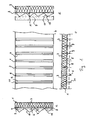
- FIG. 1 shows in FIGS. 1a to 1c the reinforced insulating body 1 in different views for a composite thermal insulation wall 2 according to FIG. 1d.
- the reinforced insulating body has several stable, solid insulation boards 3 of conventional insulation materials.
- spaced grooves 5 are arranged in the surface, engage in the folds 8 a support plate 7 on the fixing supports 6.
- the fixing body 6 are arranged so that they also cover the shock at aneinader unfamiliar insulation boards.
- the Fixiertown 6 has a conventional reinforcing grid 11, which is perpendicular to the respective Support plate 7 extends away.
- FIG. 1d shows the thermal insulation composite wall 2 with the finished applied concrete layer 15.
- FIG. 2 shows in FIGS. 2a to 2c an armored insulating body 1 'in various illustrations for a sandwich wall 2', which has the construction described in connection with FIG. 1 on both sides of the insulating panel 3.
- the same parts are therefore provided with the same reference numerals, regardless of the fact that the resulting wall thicknesses are different.
- stabilizing elements in the form of support anchors 12 and Torsionsankern 13 are still provided in this embodiment, which are plate-shaped in this embodiment.
- the stabilizing elements protrude on both sides of the insulation board 3 out. These serve to fix the entire wall in a manner familiar to the person skilled in the art in order to counteract changes due to temperature fluctuations.
- FIG. 2 d shows the finished sandwich wall 16 with concrete layers 17 and 18 arranged on both sides.
Landscapes
- Engineering & Computer Science (AREA)
- Architecture (AREA)
- Structural Engineering (AREA)
- Civil Engineering (AREA)
- Physics & Mathematics (AREA)
- Manufacturing & Machinery (AREA)
- Chemical & Material Sciences (AREA)
- Ceramic Engineering (AREA)
- Mechanical Engineering (AREA)
- Acoustics & Sound (AREA)
- Electromagnetism (AREA)
- Building Environments (AREA)
- Panels For Use In Building Construction (AREA)
- Filling Or Discharging Of Gas Storage Vessels (AREA)
Abstract
Description
- Die vorliegende Erfindung betrifft einen bewehrten Dämmkörper für eine wärmegedämmte Fertigteilwand aus Beton und Dämmung. Sie betrifft außerdem eine mit dem Dämmkörper hergestellte Fertigteilwand sowie ein Verfahren zu deren Herstellung.
- Wärmegedämmte Fertigteilwände sind allgemein bekannt. Es gibt sie in verschiedenen Ausführungen, zum einen als einseitig gedämmte Fertigteilwände (Wärmedämm-Verbundwand), die auf der Baustelle noch ausgegossen werden müssen, oder bereits fertig im Werk hergestellte, einseitig gedämmte Fertigteilwände, bei denen die Wärmedämmung in Form von Wärmedämmplatten auf den liegenden Beton aufgedrückt und beim Aushärten mit diesem verbunden werden. Des Weiteren gibt es die sogenannten Sandwich-Wände, die beidseitig des Dämmmaterials, üblicherweise in Form von Dämmplatten, beidseitig eine Betonschale aufweisen. Die Wandstärken dieser Betonschalen sind üblicherweise entsprechend ihrer Funktion als Außenwand oder als Innenwand unterschiedlich stark. Insbesondere die Herstellung der Sandwich-Fertigteilwände ist aufwändig, und ihre Größe ist auf Grund des Transportmaßes zu der Baustelle beschränkt. Üblicherweise werden diese Wände liegend hergestellt, indem zuerst eine Betonschicht mit den eingedrückten Dämmplatten hergestellt, getrocknet und anschließend gewendet in eine zweite Betonschicht eingepresst wird. Diese Herstellung ist zeit- und arbeitsaufwändig.
- Der vorliegenden Erfindung liegt daher die Aufgabe zu Grunde, eine Möglichkeit vorzuschlagen, bei der die Herstellung einer Wärmedämm-Verbundwand oder Sandwich-Wand vereinfacht ist und die es darüber hinaus erlaubt, gedämmte Fertigteilwände einfach auf der Baustelle fertig zu stellen.
- Diese Aufgabe wird erfindungsgemäß durch einen bewehrten Dämmkörper mit den Merkmalen des Anspruchs 1 und durch eine Fertigteilwand mit diesem bewehrten Dämmkörper mit den Merkmalen des Anspruchs 6 gelöst, sowie durch ein Verfahren zur Herstellung derselben nach dem nebengeordneten Verfahrensanspruch 7. Weitere vorteilhafte Ausgestaltungen sind den jeweiligen rückbezogenen Unteransprüchen zu entnehmen.
- Gemäß der Erfindung weist der bewehrte Dämmkörper mindestens eine Dämmplatte auf, an der mindestens einseitig voneinander beabstandete und senkrecht zu der Flachseite der Dämmplatte angeordnete Fixierelemente befestigt sind. Die Fixierelemente verlaufen im Wesentlichen über die gesamte Breite der Flachseite und können das übliche Gitterträgerprofil aufweisen. Wichtig dabei ist, dass diese Fixierelemente stabil an der Dämmplatte befestigt sind, um diese Dämmplatte später beim Betonieren zu fixieren. Des Weiteren weist der bewehrte Dämmkörper mindestens eine an den Fixierelementen entfernt von der Dämmplatte an diesen angeordnete Bewehrungsmatte auf. Grundsätzlich ist es möglich, diese Bewehrungsmatte in der üblichen Art und Weise an den Enden der Fixierelemente zu befestigen, jedoch ist es auch denkbar, abhängig von der Ausgestaltung der Fixierelemente die Bewehrungsmatten derart anzuordnen, dass die Fixierelemente diese noch überragen. Außerdem weist der bewehrte Dämmkörper noch Abstandshalter an den den Dämmplatten fernen Enden der Fixierelemente und/oder auf der den Dämmplatten abgewandten Seite der Bewehrungsmatte auf, um damit einen Abstand zu der äußeren Oberfläche der späteren Betonwand herzustellen.
- Der bewehrte Dämmkörper weist gemäß einer weiteren Ausbildung Fixierelemente mit einer Tragplatte auf, die an der Dämmplatte anliegen. Vorzugsweise weist die Tragplatte in Richtung Dämmplatte weisende Eingriffskanten für den Eingriff in entsprechende Nuten in der Dämmplatte auf. Damit werden die Fixierelemente sicher und Kräfte übertragend an der Dämmplatte fixiert, um die beim Betonieren auftretenden Kräfte abzufangen.
- Gemäß einer weiteren Ausbildung des erfindungsgemäßen bewehrten Dämmkörpers sind die Fixierkörper mit der Dämmplatte verklebt. Dies ermöglicht die einfache und schnelle Erstellung des Dämmkörpers.
- Bei der Verwendung eines bewehrten Dämmkörpers in einer Sandwich-Platte mit beidseitig der Dämmplatte angeordneten Fixierelementen ragen aus der Dämmplatte beidseitig Stabilisierungselemente heraus, die unerwünschte Bewegungen in der Fertigteilwand verhindern. Bei diesen Stabilisierungselementen handelt es sich um bekannte plattenförmige, aus Metall oder Kunststoff oder Kohlefasern bestehende Traganker, zylindrische Torsionsanker und U-förmige Verbundnadeln.
- Gemäß einer besonders bevorzugten Ausgestaltung der Erfindung ist der bewehrte Dämmkörper als Gesamteinheit beweg- und transportierbar, so dass er auch auf der Baustelle zwischen vertikal angeordneten Schalungstafeln einsetzbar ist. Der bewehrte Dämmkörper kann im Werk oder auch auf der Baustelle hergestellt und/oder weiter verarbeitet werden. Er kann entweder in eine vorhandene Batterieschalung oder in eine aus einzelnen Schalungsteilen zusammengestellte Schalungswand, mit vertikal angeordneten Schalungszwischenräumen, stehend eingesetzt werden. Diese kann von oben her erfolgen oder bei seitlich noch nicht geschlossenen Schalungsraum von der Seite her, bevor der Schalungsraum durch Hinzufügen einer zweiten Schalungswand seitlich geschlossen wird. Das Besondere ist, dass es hiermit möglich ist, eine gedämmte Fertigteilwand in einer senkrechten Stellung herzustellen, indem dann von oben in den Zwischenraum oder die Zwischenräume Ortbeton eingeführt wird.
- Natürlich kann der bewehrte Dämmkörper auch liegend in eine horizontal ausgerichtete, nach oben offene Schalungsform für eine Wärmeverbundwand eingebracht werden. Dabei kann der Dämmkörper von oben in die Schalungsform eingesetzt werden, wenn diese noch nicht, teilweise oder vollständig mit Ortbeton gefüllt ist. Zur fehlerfreien, vollständigen Einbettung des Dämmkörpers in den Ortbeton ist es hilfreich, den Dämmkörper in den Ortbeton einzurütteln. Dies kann durch Rütteln des Dämmkörpers und/oder des Ortbetons oder auch durch Rütteln der Schalungsform zusammen mit dem Dämmkörper und dem Ortbeton erfolgen.
- Gemäß dem erfindungsgemäßen Verfahren erfolgt die Herstellung einer gedämmten Fertigteilwand aus Beton und einer Dämmschicht als Verbund von Dämmmaterial mit Beton, in den folgenden Schritten:
- Herstellen eines Dämmkörpers mit einer Dämmplatte und daran angebrachter Bewehrung;
- Bereitstellen eines seitlich abgeschalten Vergussraumes für den Dämmkörper;
- Einbringen des Dämmkörpers in den Vergussraum und Fixieren im Vergussraum;
- Verfüllen des zwischen dem Dämmkörper und der Abschalung gebildeten Hohlraumes mit Ortbeton von oben; und
- Verdichten des Ortbetons.
- Es hat sich als zweckmäßig erwiesen, den Vergussraum für das Einbringen des Dämmkörpers einseitig an einer Flach- oder Stirnseite offen zu lassen und erst dann zu verschließen, wenn der Dämmkörper in den Vergussraum eingebracht, ausgerichtet und fixiert ist. Dies erleichtert die dabei notwendigen Arbeiten.
- Vorzugsweise wird ein Dämmkörper verwendet, der beidseitig der Dämmplatte einen Hohlraum zwischen der Dämmplatte und der Abschalung bildet, wobei in einem Arbeitsgang die Hohlräume mit Ortbeton gefüllt werden, um eine Sandwich-Wand herzustellen. Zur Aufnahme von Kräften werden in dem Dämmkörper Stabilisierungselemente angeordnet.
- Der Dämmkörper wird dabei wie folgt hergestellt:
- Bereitstellen einer Dämmplatte;
- Einbringen von beabstandeten, definierten Nuten auf mindestens einer Flachseite;
- Bereitstellen von Fixierelementen mit einer Tragplatte und aus der Oberfläche heraus ragenden Eingriffskanten;
- Verkleben der Fixierelemente auf der Flachseite mit der Tragplatte, wobei die Eingriffskanten in die Nuten der Flachseite eingreifen;
- Anbringen von Bewehrungsmatten an den Fixierelementen entfernt von der Dämmplatte;
- Anbringen von Abstandshaltern an den Fixierelementen und/oder Bewehrungsmatten zur Erzeugung eines Abstandes zwischen diesen und der Seitenabschalung.
- Mit dem erfindungsgemäß ausgebildeten bewehrten Dämmkörper können gedämmte Fertigteilwände mit schalungsglatten Wänden zur direkten weiteren Bearbeitung hergestellt werden. Durch zusätzliches Einlegen von Strukturen an der Abschalung kann die Oberfläche wahlweise auch mit einer Struktur ausgebildet werden. Das senkrechte Herstellen der Wände direkt an der Baustelle reduziert den Arbeitsaufwand und darüber hinaus auch die Transportkosten.
- Der Gegenstand der vorliegenden Erfindung ergibt sich nicht nur aus dem Gegenstand der einzelnen Schutzansprüche, sondern auch aus der Kombination der einzelnen Schutzansprüche untereinander. Alle in den Unterlagen offenbarten Merkmale, insbesondere die in der Zeichnung dargestellten Ausbildungen, werden als erfindungswesentlich beansprucht, soweit sie einzeln oder in Kombination miteinander gegenüber dem Stand der Technik neu sind.
- Nachfolgend wird die Erfindung anhand von Ausführungsbeispielen in Verbindung mit einem bewehrten Dämmkörper näher erläutert. Hierbei gehen aus den Figuren der Zeichnung und ihrer Beschreibung weitere wesentliche Merkmale und Vorteile der Erfindung hervor.
- Es stellen dar:
- Figur 1
- die Draufsicht (Figur 1a), den Horizontalschnitt (Figur 1b), den Vertikalschnitt (Figur 1c) eines bewehrten Dämmkörpers für eine Wärmedämm-Verbundwand sowie eine Wärmedämm-Verbundwand (Figur 1d); und
- Figur 2
- die Draufsicht (Figur 2a), den Horizontalschnitt (Figur 2b) und den Vertikalschnitt (Figur 2c) eines bewehrten Dämmkörpers für eine Sandwich-Wand sowie eine Sandwich-Wand (Figur 2d).
- Figur 1 zeigt in den Figuren 1a bis 1c den bewehrten Dämmkörper 1 in verschiedenen Ansichten für eine Wärmedämm-Verbundwand 2 gemäß Figur 1d. Der bewehrte Dämmkörper weist mehrere stabile, feste Dämmplatten 3 aus üblichen Dämmmaterialien auf. Auf der einen Flachseite 4 sind in der Oberfläche voneinander beabstandete Nuten 5 angeordnet, in die Abkantungen 8 einer Tragplatte 7 an den Fixierträgern 6 eingreifen. Die Fixierkörper 6 sind so angeordnet, dass sie auch den Stoß bei aneinadergrenzenden Dämmplatten überdecken. Die Befestigung der Fixierträger 6 erfolgt über einen Klebstoff zwischen der Tragplatte 7 und der Flachseite 4. Der Fixierträger 6 weist ein übliches Bewehrungsgitter 11 auf, das sich senkrecht von der jeweiligen Tragplatte 7 weg erstreckt. Zwischen den Fixierträgern 6 befindet sich im Wesentlichen parallel zu der Dämmplatte 3 die übliche Bewehrung, beispielsweise in Form von Baustahlmatten. Im Ausführungsbeispiel sind am Ende der Bewehrungsgitter noch Abstandshalter angeordnet, die die Bewehrung von der Betonoberfläche der fertigen Wärmedämm-Verbundwand 2 entfernt halten. Figur 1d zeigt die Wärmedämm-Verbundwand 2 mit der fertig aufgebrachten Betonschicht 15.
- Figur 2 zeigt in den Figuren 2a bis 2c einen bewehrten Dämmkörper 1' in verschiedenen Darstellungen für eine Sandwich-Wand 2', der beidseitig der Dämmplatte 3 den im Zusammenhang mit Figur 1 beschriebenen Aufbau aufweist. Gleiche Teile sind daher mit gleichen Bezugszeichen versehen, unabhängig davon dass die sich am Ende ergebenden Wandstärken unterschiedlich sind. Zusätzlich sind bei dieser Ausgestaltung noch Stabilisierungselemente in Form von Tragankern 12 und Torsionsankern 13 vorgesehen, die in diesem Ausführungsbeispiel plattenförmig ausgebildet sind. Zusätzlich befinden sich noch horizontal angeordnete U-förmige Verbundnadeln 14 in dem bewehrten Dämmkörper 1. Die Stabilisierungselemente ragen beidseitig aus der Dämmplatte 3 heraus. Diese dienen in dem Fachmann geläufiger Art und Weise der Fixierung der gesamten Wand, um Veränderungen durch Temperaturschwankungen entgegen zu wirken. Figur 2d zeigt die fertige Sandwich-Wand 16 mit beidseitig angeordneten Betonschichten 17 und 18.
Claims (8)
- Bewehrter Dämmkörper für eine gedämmte Fertigteilwand aus Beton und Dämmung, gekennzeichnet durch
mindestens eine Dämmplatte (3);
mindestens einseitig der Dämmplatte (3) an dieser befestigte, voneinander beabstandete und senkrecht zu der Flachseite (4) angeordnete Fixierelemente (6);
mindestens eine an den Fixierelementen (6) entfernt von der Dämmplatte (3) an diesen befestigten Bewehrungsmatte (9);
Abstandshalter (10) an den den Dämmplatten (3) fernen Enden der Fixierelemente (6) und/oder auf der der Dämmplatte (3) abgewandten Seite der Bewehrungsmatte (9). - Bewehrter Dämmkörper nach Anspruch 1, dadurch gekennzeichnet, dass die Fixierelemente (6) eine Tragplatte (7) aufweisen, die an der Dämmplatte (3) anliegt und vorzugsweise in Richtung Dämmplatte weisende Eingriffskanten (8) für den Eingriff in entsprechende Nuten (5) in der Dämmplatte (3) aufweist.
- Bewehrter Dämmkörper nach Anspruch 2, dadurch gekennzeichnet, dass die Fixierelemente (6) mit der Dämmplatte (3) verklebt sind.
- Bewehrter Dämmkörper mit beidseitig der Dämmplatte (3) angeordneten Fixierelementen (6) nach einem der voran gegangenen Ansprüche, dadurch gekennzeichnet, dass aus der Dämmplatte (3) beidseitig Stabilisierungselemente (12, 13, 14) heraus ragen.
- Bewehrter Dämmkörper nach einem der voran gegangenen Ansprüche, dadurch gekennzeichnet, dass er zwischen vertikal angeordneten Schalungstafeln einsetzbar ist.
- Fertigteilwand, gekennzeichnet durch einen bewehrten Dämmkörper (1, 1') nach einem der voran gegangenen Ansprüche 1 bis 5.
- Verfahren zur Herstellung einer gedämmten Fertigteilwand aus Beton mit einem bewehrten Dämmkörper, gekennzeichnet durch die folgenden Schritte:• Herstellen eines Dämmkörpers mit einer Dämmplatte und daran angebrachter Bewehrung;• Bereitstellen eines seitlich abgeschalten Vergussraumes für den Dämmkörper;• Einbringen des Dämmkörpers in den Vergussraum und Fixieren im Vergussraum;• Verfüllen des zwischen dem Dämmkörper und der Abschalung gebildeten Hohlraumes mit Ortbeton.
- Verfahren nach Anspruch 7, dadurch gekennzeichnet, dass der bewehrte Dämmkörper in folgenden Schritten hergestellt wird:• Bereitstellen einer Dämmplatte;• Einbringen von beabstandeten, definierten Nuten auf mindestens einer Flachseite;• Bereitstellen von Fixierelementen mit einer Tragplatte und aus der Oberfläche heraus ragenden Eingriffskanten;• Verkleben der Fixierelemente auf der Flachseite mit der Tragplatte, wobei die Eingriffskanten in die Nuten der Flachseite eingreifen;• Anbringen von Bewehrungsmatten an den Fixierelementen entfernt von der Dämmplatte;und• Anbringen von Abstandshaltern an den Fixierelementen und/oder Bewehrungsmatten zur Erzeugung eines Abstandes zwischen diesen und der Seitenabschalung.
Priority Applications (2)
| Application Number | Priority Date | Filing Date | Title |
|---|---|---|---|
| PL06015305T PL1783293T3 (pl) | 2005-11-02 | 2006-07-22 | Zbrojony element izolacyjny dla termoizolacyjnej ściany prefabrykowanej i ściana przefabrykowana jak również sposób jej wytwarzania |
| SI200630230T SI1783293T1 (sl) | 2005-11-02 | 2006-07-22 | Ojaäśeno izolacijsko telo za predfabriciran stenski izolacijski element in stenski element in postopek za proizvodnjo |
Applications Claiming Priority (1)
| Application Number | Priority Date | Filing Date | Title |
|---|---|---|---|
| DE202005017046U DE202005017046U1 (de) | 2005-11-02 | 2005-11-02 | Bewehrter Dämmkörper für eine wärmegedämmte Fertigteilwand und Fertigteilwand |
Publications (3)
| Publication Number | Publication Date |
|---|---|
| EP1783293A2 true EP1783293A2 (de) | 2007-05-09 |
| EP1783293A3 EP1783293A3 (de) | 2007-11-14 |
| EP1783293B1 EP1783293B1 (de) | 2008-12-17 |
Family
ID=36062620
Family Applications (1)
| Application Number | Title | Priority Date | Filing Date |
|---|---|---|---|
| EP06015305A Not-in-force EP1783293B1 (de) | 2005-11-02 | 2006-07-22 | Bewehrter Dämmkörper für eine wärmegedämmte Fertigteilwand und Fertigteilwand sowie Verfahren zur Herstellung |
Country Status (8)
| Country | Link |
|---|---|
| EP (1) | EP1783293B1 (de) |
| AT (1) | ATE417971T1 (de) |
| DE (2) | DE202005017046U1 (de) |
| DK (1) | DK1783293T3 (de) |
| ES (1) | ES2318627T3 (de) |
| PL (1) | PL1783293T3 (de) |
| PT (1) | PT1783293E (de) |
| SI (1) | SI1783293T1 (de) |
Cited By (1)
| Publication number | Priority date | Publication date | Assignee | Title |
|---|---|---|---|---|
| CN109016093A (zh) * | 2018-08-27 | 2018-12-18 | 泗县汉能诚信电气工程有限公司 | 一种装配式墙板立模浇筑平台 |
Families Citing this family (3)
| Publication number | Priority date | Publication date | Assignee | Title |
|---|---|---|---|---|
| EP1959069B1 (de) * | 2007-02-13 | 2009-05-06 | Iconorm GmbH | Bewehrter Dämmkörper für eine einseitig wärmegedämmte Fertigteilwand und Fertigteilwand sowie Verfahren zur Herstellung |
| EP2011616B1 (de) | 2007-07-06 | 2010-06-30 | Iconorm GmbH | Dämmkörper für eine wärmegedämmte Betonwand und wärmegedämmte Betonwand sowie Verfahren zur Herstellung |
| ATE452254T1 (de) * | 2007-11-23 | 2010-01-15 | Finja Ab | Fertigteilwand mit einem rahmen zur befestigung von platten |
Citations (2)
| Publication number | Priority date | Publication date | Assignee | Title |
|---|---|---|---|---|
| DE1804703A1 (de) | 1968-10-23 | 1970-05-27 | Schwarz & Meissner Gmbh | Vorgefertigte Bewehrung fuer Stahlbetonbretter |
| EP0586361A1 (de) | 1992-09-04 | 1994-03-09 | Cc+F Consulting, Construction And Finance Ag | Bauelement |
-
2005
- 2005-11-02 DE DE202005017046U patent/DE202005017046U1/de not_active Expired - Lifetime
-
2006
- 2006-07-22 DK DK06015305T patent/DK1783293T3/da active
- 2006-07-22 EP EP06015305A patent/EP1783293B1/de not_active Not-in-force
- 2006-07-22 PL PL06015305T patent/PL1783293T3/pl unknown
- 2006-07-22 DE DE502006002368T patent/DE502006002368D1/de active Active
- 2006-07-22 SI SI200630230T patent/SI1783293T1/sl unknown
- 2006-07-22 ES ES06015305T patent/ES2318627T3/es active Active
- 2006-07-22 PT PT06015305T patent/PT1783293E/pt unknown
- 2006-07-22 AT AT06015305T patent/ATE417971T1/de active
Patent Citations (2)
| Publication number | Priority date | Publication date | Assignee | Title |
|---|---|---|---|---|
| DE1804703A1 (de) | 1968-10-23 | 1970-05-27 | Schwarz & Meissner Gmbh | Vorgefertigte Bewehrung fuer Stahlbetonbretter |
| EP0586361A1 (de) | 1992-09-04 | 1994-03-09 | Cc+F Consulting, Construction And Finance Ag | Bauelement |
Cited By (1)
| Publication number | Priority date | Publication date | Assignee | Title |
|---|---|---|---|---|
| CN109016093A (zh) * | 2018-08-27 | 2018-12-18 | 泗县汉能诚信电气工程有限公司 | 一种装配式墙板立模浇筑平台 |
Also Published As
| Publication number | Publication date |
|---|---|
| DK1783293T3 (da) | 2009-04-20 |
| ES2318627T3 (es) | 2009-05-01 |
| SI1783293T1 (sl) | 2009-06-30 |
| EP1783293A3 (de) | 2007-11-14 |
| DE502006002368D1 (de) | 2009-01-29 |
| PL1783293T3 (pl) | 2009-06-30 |
| ATE417971T1 (de) | 2009-01-15 |
| EP1783293B1 (de) | 2008-12-17 |
| PT1783293E (pt) | 2009-03-16 |
| DE202005017046U1 (de) | 2006-03-02 |
Similar Documents
| Publication | Publication Date | Title |
|---|---|---|
| DE60314459T2 (de) | Bauelement für die mantelbetonbauweise | |
| EP2557243A2 (de) | Bauelement zur Wärmedämmung | |
| EP2963205A1 (de) | Vorrichtung zur schalung | |
| EP1760208B1 (de) | System und Verfahren zur Herstellung von gedämmten Hohlwänden | |
| EP1482101A1 (de) | Wandbauelement, Verfahren zur Herstellung eines Wandbauelements und ein Verbindungsmittel für ein Wandbauelement | |
| EP1783293B1 (de) | Bewehrter Dämmkörper für eine wärmegedämmte Fertigteilwand und Fertigteilwand sowie Verfahren zur Herstellung | |
| AT519093A4 (de) | Verbindungsvorrichtung zur Verbindung von dünnwandigen Fertigteilen und damit ausgestattete Fertigteile | |
| EP2209952A1 (de) | Abstandhalter und bauteil zur herstellung einer wandkonstruktion sowie verfahren und vorrichtung | |
| EP2189586B1 (de) | Plattenelement mit Verstärkung | |
| EP1959069B1 (de) | Bewehrter Dämmkörper für eine einseitig wärmegedämmte Fertigteilwand und Fertigteilwand sowie Verfahren zur Herstellung | |
| EP2792805B1 (de) | Wandbauteil bestehend aus Halbfertig-Bauteilen | |
| EP1592852B1 (de) | Verlorener schalungsk rper | |
| EP3299524B1 (de) | Fertigteilmauer und verfahren zur herstellung derselben | |
| DE10259961B4 (de) | Vorgefertigtes Bauelement, insbesondere Decken- oder Wandbauelement aus einem ausgehärteten Material | |
| EP1887155B1 (de) | Thermisch isolierendes Bauelement | |
| EP4455421B1 (de) | Flächenhaftes paneel und verfahren zum herstellen eines derartigen paneels | |
| DE10218758B4 (de) | Schalungsplatte mit Wabenkern | |
| DE19625514C2 (de) | Schalenbauteil für Wände oder Decken und Verfahren zur Herstellung des Schalenbauteils | |
| DE8604345U1 (de) | Schalungselement für Betonbauteile | |
| DE2815080A1 (de) | Schalkoerper | |
| DE3232696C1 (de) | Schalungselement | |
| DE102024100880A1 (de) | Schalungselement | |
| DE202016105371U1 (de) | Fertigteilmauer | |
| DE202006000144U1 (de) | Wärmeisolierende Schalungsform | |
| DE202023107453U1 (de) | Vorgefertigter Baublock mit gebrauchsfertiger Wärmedämmung für die Fassade |
Legal Events
| Date | Code | Title | Description |
|---|---|---|---|
| PUAI | Public reference made under article 153(3) epc to a published international application that has entered the european phase |
Free format text: ORIGINAL CODE: 0009012 |
|
| AK | Designated contracting states |
Kind code of ref document: A2 Designated state(s): AT BE BG CH CY CZ DE DK EE ES FI FR GB GR HU IE IS IT LI LT LU LV MC NL PL PT RO SE SI SK TR |
|
| AX | Request for extension of the european patent |
Extension state: AL BA HR MK YU |
|
| PUAL | Search report despatched |
Free format text: ORIGINAL CODE: 0009013 |
|
| AK | Designated contracting states |
Kind code of ref document: A3 Designated state(s): AT BE BG CH CY CZ DE DK EE ES FI FR GB GR HU IE IS IT LI LT LU LV MC NL PL PT RO SE SI SK TR |
|
| AX | Request for extension of the european patent |
Extension state: AL BA HR MK YU |
|
| 17P | Request for examination filed |
Effective date: 20080424 |
|
| AKX | Designation fees paid |
Designated state(s): AT BE BG CH CY CZ DE DK EE ES FI FR GB GR HU IE IS IT LI LT LU LV MC NL PL PT RO SE SI SK TR |
|
| GRAP | Despatch of communication of intention to grant a patent |
Free format text: ORIGINAL CODE: EPIDOSNIGR1 |
|
| GRAS | Grant fee paid |
Free format text: ORIGINAL CODE: EPIDOSNIGR3 |
|
| GRAA | (expected) grant |
Free format text: ORIGINAL CODE: 0009210 |
|
| AK | Designated contracting states |
Kind code of ref document: B1 Designated state(s): AT BE BG CH CY CZ DE DK EE ES FI FR GB GR HU IE IS IT LI LT LU LV MC NL PL PT RO SE SI SK TR |
|
| REG | Reference to a national code |
Ref country code: GB Ref legal event code: FG4D Free format text: NOT ENGLISH |
|
| REG | Reference to a national code |
Ref country code: CH Ref legal event code: EP |
|
| REG | Reference to a national code |
Ref country code: IE Ref legal event code: FG4D Free format text: LANGUAGE OF EP DOCUMENT: GERMAN |
|
| REF | Corresponds to: |
Ref document number: 502006002368 Country of ref document: DE Date of ref document: 20090129 Kind code of ref document: P |
|
| REG | Reference to a national code |
Ref country code: RO Ref legal event code: EPE |
|
| REG | Reference to a national code |
Ref country code: CH Ref legal event code: NV Representative=s name: ABACUS PATENTANWAELTE KLOCKE SPAETH BARTH |
|
| REG | Reference to a national code |
Ref country code: PT Ref legal event code: SC4A Free format text: AVAILABILITY OF NATIONAL TRANSLATION Effective date: 20090305 |
|
| REG | Reference to a national code |
Ref country code: SE Ref legal event code: TRGR |
|
| REG | Reference to a national code |
Ref country code: GR Ref legal event code: EP Ref document number: 20090400745 Country of ref document: GR |
|
| REG | Reference to a national code |
Ref country code: DK Ref legal event code: T3 |
|
| PG25 | Lapsed in a contracting state [announced via postgrant information from national office to epo] |
Ref country code: LT Free format text: LAPSE BECAUSE OF FAILURE TO SUBMIT A TRANSLATION OF THE DESCRIPTION OR TO PAY THE FEE WITHIN THE PRESCRIBED TIME-LIMIT Effective date: 20081217 |
|
| REG | Reference to a national code |
Ref country code: ES Ref legal event code: FG2A Ref document number: 2318627 Country of ref document: ES Kind code of ref document: T3 |
|
| PG25 | Lapsed in a contracting state [announced via postgrant information from national office to epo] |
Ref country code: LV Free format text: LAPSE BECAUSE OF FAILURE TO SUBMIT A TRANSLATION OF THE DESCRIPTION OR TO PAY THE FEE WITHIN THE PRESCRIBED TIME-LIMIT Effective date: 20081217 |
|
| REG | Reference to a national code |
Ref country code: PL Ref legal event code: T3 |
|
| PG25 | Lapsed in a contracting state [announced via postgrant information from national office to epo] |
Ref country code: EE Free format text: LAPSE BECAUSE OF FAILURE TO SUBMIT A TRANSLATION OF THE DESCRIPTION OR TO PAY THE FEE WITHIN THE PRESCRIBED TIME-LIMIT Effective date: 20081217 |
|
| REG | Reference to a national code |
Ref country code: HU Ref legal event code: AG4A Ref document number: E005407 Country of ref document: HU |
|
| PG25 | Lapsed in a contracting state [announced via postgrant information from national office to epo] |
Ref country code: IS Free format text: LAPSE BECAUSE OF FAILURE TO SUBMIT A TRANSLATION OF THE DESCRIPTION OR TO PAY THE FEE WITHIN THE PRESCRIBED TIME-LIMIT Effective date: 20090417 |
|
| PLBE | No opposition filed within time limit |
Free format text: ORIGINAL CODE: 0009261 |
|
| STAA | Information on the status of an ep patent application or granted ep patent |
Free format text: STATUS: NO OPPOSITION FILED WITHIN TIME LIMIT |
|
| 26N | No opposition filed |
Effective date: 20090918 |
|
| PG25 | Lapsed in a contracting state [announced via postgrant information from national office to epo] |
Ref country code: MC Free format text: LAPSE BECAUSE OF NON-PAYMENT OF DUE FEES Effective date: 20090731 |
|
| PGFP | Annual fee paid to national office [announced via postgrant information from national office to epo] |
Ref country code: RO Payment date: 20100617 Year of fee payment: 5 |
|
| PGFP | Annual fee paid to national office [announced via postgrant information from national office to epo] |
Ref country code: CZ Payment date: 20100624 Year of fee payment: 5 Ref country code: SK Payment date: 20100623 Year of fee payment: 5 |
|
| PGFP | Annual fee paid to national office [announced via postgrant information from national office to epo] |
Ref country code: ES Payment date: 20100813 Year of fee payment: 5 Ref country code: HU Payment date: 20100712 Year of fee payment: 5 Ref country code: IE Payment date: 20100712 Year of fee payment: 5 |
|
| PGFP | Annual fee paid to national office [announced via postgrant information from national office to epo] |
Ref country code: BG Payment date: 20100714 Year of fee payment: 5 Ref country code: FI Payment date: 20100712 Year of fee payment: 5 Ref country code: FR Payment date: 20100805 Year of fee payment: 5 Ref country code: IT Payment date: 20100722 Year of fee payment: 5 Ref country code: LU Payment date: 20100716 Year of fee payment: 5 Ref country code: SE Payment date: 20100708 Year of fee payment: 5 Ref country code: SI Payment date: 20100615 Year of fee payment: 5 Ref country code: TR Payment date: 20100625 Year of fee payment: 5 |
|
| PGFP | Annual fee paid to national office [announced via postgrant information from national office to epo] |
Ref country code: GB Payment date: 20100721 Year of fee payment: 5 Ref country code: GR Payment date: 20100615 Year of fee payment: 5 Ref country code: PL Payment date: 20100617 Year of fee payment: 5 |
|
| PGFP | Annual fee paid to national office [announced via postgrant information from national office to epo] |
Ref country code: DK Payment date: 20100712 Year of fee payment: 5 Ref country code: PT Payment date: 20100707 Year of fee payment: 5 |
|
| PG25 | Lapsed in a contracting state [announced via postgrant information from national office to epo] |
Ref country code: CY Free format text: LAPSE BECAUSE OF FAILURE TO SUBMIT A TRANSLATION OF THE DESCRIPTION OR TO PAY THE FEE WITHIN THE PRESCRIBED TIME-LIMIT Effective date: 20081217 |
|
| PGFP | Annual fee paid to national office [announced via postgrant information from national office to epo] |
Ref country code: DE Payment date: 20110731 Year of fee payment: 6 Ref country code: AT Payment date: 20110628 Year of fee payment: 6 |
|
| PGFP | Annual fee paid to national office [announced via postgrant information from national office to epo] |
Ref country code: BE Payment date: 20110712 Year of fee payment: 6 Ref country code: NL Payment date: 20110715 Year of fee payment: 6 |
|
| REG | Reference to a national code |
Ref country code: PT Ref legal event code: MM4A Free format text: LAPSE DUE TO NON-PAYMENT OF FEES Effective date: 20120123 |
|
| PGFP | Annual fee paid to national office [announced via postgrant information from national office to epo] |
Ref country code: CH Payment date: 20111024 Year of fee payment: 6 |
|
| REG | Reference to a national code |
Ref country code: SE Ref legal event code: EUG |
|
| REG | Reference to a national code |
Ref country code: DK Ref legal event code: EBP |
|
| GBPC | Gb: european patent ceased through non-payment of renewal fee |
Effective date: 20110722 |
|
| REG | Reference to a national code |
Ref country code: GR Ref legal event code: ML Ref document number: 20090400745 Country of ref document: GR Effective date: 20120202 |
|
| REG | Reference to a national code |
Ref country code: SI Ref legal event code: KO00 Effective date: 20120227 |
|
| REG | Reference to a national code |
Ref country code: SK Ref legal event code: MM4A Ref document number: E 5244 Country of ref document: SK Effective date: 20110722 |
|
| REG | Reference to a national code |
Ref country code: FR Ref legal event code: ST Effective date: 20120330 |
|
| REG | Reference to a national code |
Ref country code: IE Ref legal event code: MM4A |
|
| PG25 | Lapsed in a contracting state [announced via postgrant information from national office to epo] |
Ref country code: CZ Free format text: LAPSE BECAUSE OF NON-PAYMENT OF DUE FEES Effective date: 20110722 Ref country code: FR Free format text: LAPSE BECAUSE OF NON-PAYMENT OF DUE FEES Effective date: 20110801 Ref country code: SK Free format text: LAPSE BECAUSE OF NON-PAYMENT OF DUE FEES Effective date: 20110722 Ref country code: HU Free format text: LAPSE BECAUSE OF NON-PAYMENT OF DUE FEES Effective date: 20110723 |
|
| PG25 | Lapsed in a contracting state [announced via postgrant information from national office to epo] |
Ref country code: FI Free format text: LAPSE BECAUSE OF NON-PAYMENT OF DUE FEES Effective date: 20110722 Ref country code: PT Free format text: LAPSE BECAUSE OF NON-PAYMENT OF DUE FEES Effective date: 20120123 Ref country code: GR Free format text: LAPSE BECAUSE OF NON-PAYMENT OF DUE FEES Effective date: 20120202 Ref country code: IT Free format text: LAPSE BECAUSE OF NON-PAYMENT OF DUE FEES Effective date: 20110722 Ref country code: SI Free format text: LAPSE BECAUSE OF NON-PAYMENT OF DUE FEES Effective date: 20110723 |
|
| PG25 | Lapsed in a contracting state [announced via postgrant information from national office to epo] |
Ref country code: GB Free format text: LAPSE BECAUSE OF NON-PAYMENT OF DUE FEES Effective date: 20110722 |
|
| PG25 | Lapsed in a contracting state [announced via postgrant information from national office to epo] |
Ref country code: DK Free format text: LAPSE BECAUSE OF NON-PAYMENT OF DUE FEES Effective date: 20110731 Ref country code: IE Free format text: LAPSE BECAUSE OF NON-PAYMENT OF DUE FEES Effective date: 20110722 |
|
| PG25 | Lapsed in a contracting state [announced via postgrant information from national office to epo] |
Ref country code: PL Free format text: LAPSE BECAUSE OF NON-PAYMENT OF DUE FEES Effective date: 20110722 Ref country code: RO Free format text: LAPSE BECAUSE OF NON-PAYMENT OF DUE FEES Effective date: 20110722 |
|
| REG | Reference to a national code |
Ref country code: PL Ref legal event code: LAPE |
|
| BERE | Be: lapsed |
Owner name: ICONORM G.M.B.H. Effective date: 20120731 |
|
| REG | Reference to a national code |
Ref country code: NL Ref legal event code: V1 Effective date: 20130201 |
|
| REG | Reference to a national code |
Ref country code: CH Ref legal event code: PL |
|
| REG | Reference to a national code |
Ref country code: AT Ref legal event code: MM01 Ref document number: 417971 Country of ref document: AT Kind code of ref document: T Effective date: 20120722 |
|
| PG25 | Lapsed in a contracting state [announced via postgrant information from national office to epo] |
Ref country code: DE Free format text: LAPSE BECAUSE OF NON-PAYMENT OF DUE FEES Effective date: 20130201 Ref country code: NL Free format text: LAPSE BECAUSE OF NON-PAYMENT OF DUE FEES Effective date: 20130201 Ref country code: SE Free format text: LAPSE BECAUSE OF NON-PAYMENT OF DUE FEES Effective date: 20110723 Ref country code: CH Free format text: LAPSE BECAUSE OF NON-PAYMENT OF DUE FEES Effective date: 20120731 Ref country code: LI Free format text: LAPSE BECAUSE OF NON-PAYMENT OF DUE FEES Effective date: 20120731 |
|
| PG25 | Lapsed in a contracting state [announced via postgrant information from national office to epo] |
Ref country code: BE Free format text: LAPSE BECAUSE OF NON-PAYMENT OF DUE FEES Effective date: 20120731 Ref country code: LU Free format text: LAPSE BECAUSE OF NON-PAYMENT OF DUE FEES Effective date: 20110722 |
|
| PG25 | Lapsed in a contracting state [announced via postgrant information from national office to epo] |
Ref country code: AT Free format text: LAPSE BECAUSE OF NON-PAYMENT OF DUE FEES Effective date: 20120722 |
|
| PG25 | Lapsed in a contracting state [announced via postgrant information from national office to epo] |
Ref country code: BG Free format text: LAPSE BECAUSE OF NON-PAYMENT OF DUE FEES Effective date: 20120630 |
|
| REG | Reference to a national code |
Ref country code: DE Ref legal event code: R119 Ref document number: 502006002368 Country of ref document: DE Effective date: 20130201 |
|
| REG | Reference to a national code |
Ref country code: ES Ref legal event code: FD2A Effective date: 20131029 |
|
| PG25 | Lapsed in a contracting state [announced via postgrant information from national office to epo] |
Ref country code: ES Free format text: LAPSE BECAUSE OF NON-PAYMENT OF DUE FEES Effective date: 20110723 Ref country code: TR Free format text: LAPSE BECAUSE OF NON-PAYMENT OF DUE FEES Effective date: 20110722 |