EP1782465B1 - Method for cleaving brittle materials - Google Patents
Method for cleaving brittle materials Download PDFInfo
- Publication number
- EP1782465B1 EP1782465B1 EP20050769112 EP05769112A EP1782465B1 EP 1782465 B1 EP1782465 B1 EP 1782465B1 EP 20050769112 EP20050769112 EP 20050769112 EP 05769112 A EP05769112 A EP 05769112A EP 1782465 B1 EP1782465 B1 EP 1782465B1
- Authority
- EP
- European Patent Office
- Prior art keywords
- blade
- bar
- crack
- cleaving
- brittle material
- Prior art date
- Legal status (The legal status is an assumption and is not a legal conclusion. Google has not performed a legal analysis and makes no representation as to the accuracy of the status listed.)
- Expired - Lifetime
Links
Images


Classifications
-
- H—ELECTRICITY
- H01—ELECTRIC ELEMENTS
- H01L—SEMICONDUCTOR DEVICES NOT COVERED BY CLASS H10
- H01L21/00—Processes or apparatus adapted for the manufacture or treatment of semiconductor or solid state devices or of parts thereof
- H01L21/02—Manufacture or treatment of semiconductor devices or of parts thereof
- H01L21/04—Manufacture or treatment of semiconductor devices or of parts thereof the devices having potential barriers, e.g. a PN junction, depletion layer or carrier concentration layer
- H01L21/18—Manufacture or treatment of semiconductor devices or of parts thereof the devices having potential barriers, e.g. a PN junction, depletion layer or carrier concentration layer the devices having semiconductor bodies comprising elements of Group IV of the Periodic Table or AIIIBV compounds with or without impurities, e.g. doping materials
- H01L21/30—Treatment of semiconductor bodies using processes or apparatus not provided for in groups H01L21/20 - H01L21/26
-
- B—PERFORMING OPERATIONS; TRANSPORTING
- B28—WORKING CEMENT, CLAY, OR STONE
- B28D—WORKING STONE OR STONE-LIKE MATERIALS
- B28D1/00—Working stone or stone-like materials, e.g. brick, concrete or glass, not provided for elsewhere; Machines, devices, tools therefor
- B28D1/22—Working stone or stone-like materials, e.g. brick, concrete or glass, not provided for elsewhere; Machines, devices, tools therefor by cutting, e.g. incising
- B28D1/222—Working stone or stone-like materials, e.g. brick, concrete or glass, not provided for elsewhere; Machines, devices, tools therefor by cutting, e.g. incising by pressing, e.g. presses
-
- B—PERFORMING OPERATIONS; TRANSPORTING
- B28—WORKING CEMENT, CLAY, OR STONE
- B28D—WORKING STONE OR STONE-LIKE MATERIALS
- B28D5/00—Fine working of gems, jewels, crystals, e.g. of semiconductor material; apparatus or devices therefor
- B28D5/04—Fine working of gems, jewels, crystals, e.g. of semiconductor material; apparatus or devices therefor by tools other than rotary type, e.g. reciprocating tools
-
- Y—GENERAL TAGGING OF NEW TECHNOLOGICAL DEVELOPMENTS; GENERAL TAGGING OF CROSS-SECTIONAL TECHNOLOGIES SPANNING OVER SEVERAL SECTIONS OF THE IPC; TECHNICAL SUBJECTS COVERED BY FORMER USPC CROSS-REFERENCE ART COLLECTIONS [XRACs] AND DIGESTS
- Y10—TECHNICAL SUBJECTS COVERED BY FORMER USPC
- Y10T—TECHNICAL SUBJECTS COVERED BY FORMER US CLASSIFICATION
- Y10T225/00—Severing by tearing or breaking
- Y10T225/10—Methods
- Y10T225/16—Transversely of continuously fed work
- Y10T225/18—Progressively to or from one side edge
-
- Y—GENERAL TAGGING OF NEW TECHNOLOGICAL DEVELOPMENTS; GENERAL TAGGING OF CROSS-SECTIONAL TECHNOLOGIES SPANNING OVER SEVERAL SECTIONS OF THE IPC; TECHNICAL SUBJECTS COVERED BY FORMER USPC CROSS-REFERENCE ART COLLECTIONS [XRACs] AND DIGESTS
- Y10—TECHNICAL SUBJECTS COVERED BY FORMER USPC
- Y10T—TECHNICAL SUBJECTS COVERED BY FORMER US CLASSIFICATION
- Y10T225/00—Severing by tearing or breaking
- Y10T225/30—Breaking or tearing apparatus
- Y10T225/371—Movable breaking tool
Definitions
- the present invention relates generally to cleaving, and more particularly, to a method for cleaving brittle materials into thin sections.
- Thin flat "wafers” of semiconductor and similar materials are useful for photovoltaics and other solid-state electronics, and substrates for various systems such as microelectromechanical system (MEMS).
- MEMS microelectromechanical system
- the conventional techniques of grinding and polishing crystals to obtain thin sections introduces defects and impurities to the crystal.
- Alternative methods of creating thin sections by additive processes have not proven to result in high quality material.
- US 3,901,423 discloses a method for fracturing crystalline methods to produce thin wafers including applying a tensile load to a silicon rod and then forcing a wedge into a previously formed notch on one or both sides of the material.
- US 4,955,357 discloses a method of cutting a polycrystalline silicon rod which comprises applying pressing forces on a plane perpendicular to the longitudinal axis of the rod towards the axis of the rod at at least two positions on the periphery of the rod symmetrical to the axis of the rod by means of wedge edges.
- the wedge edges form cutting edges and a driving means, for example a hydraulic cylinder, provides the driving force.
- a driving means for example a hydraulic cylinder
- JP 11-284-278 discloses a system in which a number of grooves are formed in a laser diode bar and a cutter is then used by inserting a cutting edge into the grooves so that a chip is removed.
- the apparatus for use in the method of the invention includes a support adapted to hold the section of the bar in a position to be cleaved, a blade, an actuator coupled to the blade for driving the blade at least partially through the bar to create a cleaved portion of the bar, and a follower for engaging the end of the bar during cleaving.
- Brittle materials generally refer to materials that can sustain only a small amount of deformation before breaking or fracturing. Silicon and other common semiconductor/substrate materials (such as gallium arsenide and sapphire) are usually hard and/or brittle. But, when in a single crystal form, thin sheets of these brittle materials are cleavable, and can be formed using embodiments of the present invention.
- a "thin” sheet, or “thin” portion generally refers to a slice or piece of the brittle material thin enough to sustain an amount of deformation prior to fracturing that is larger than when the material in bulk.
- a wafer of silicon preferably less than 200 microns thick is a thin sheet according to embodiments of the present invention.
- Other embodiments of the invention can utilize a larger or smaller thickness of silicon.
- a silicon wafer having a thickness between 50 and 200 microns is generated. Other thicknesses may also be generated in embodiments of the present invention.
- Apparatus 10 includes a bottom support element or base 12 and an upstanding structure which includes a plurality of side frame elements 14 and a top platen 16. While not shown in FIG. 1 to avoid obscuring illustration, apparatus 10 may include a pair of microscopes to aid blade positioning and alignment. A flexible band, cable, or chain, or rack and pinion (not shown) may also be included in apparatus 10 to provide rotary to linear movement translation to drive the follower 24.
- Apparatus 10 further includes a blade 18, an actuator 20 coupled to blade 18 for driving the blade at least partially through a bar or boule of brittle material 22 to create a cleaved portion of the bar, and a follower 24 for engaging the end 26 of bar 22 during cleaving.
- Apparatus 10 may include a pushing mechanism such as a pushrod 28 to feed the boule of brittle material 22. Any suitable actuator or motor, not shown, is coupled to the pushrod 28 for moving the boule 22 towards the cutting mechanism of apparatus 10.
- a guiding mechanism including a front guide 30, a rear guide 32, and a vertical guide 34 is provided to guide boule 22 into a position for cleaving.
- a fine adjustment slide 36 is provided, and the front guide 30 is preferably secured in one or more fixed positions of the slide 36 and the rear guide 32 is slidably mounted on the slide 36.
- the fine adjustment slide 36 can adjust the position of boule 22 to establish a cut depth and, in some embodiments, adjust the blade position as the cut proceeds (see FIG. 14 ).
- Front guide 30 can be a part of fine adjustment slide 36.
- Rear guide 32 can be a part of boule pushing mechanism 28 and travel along fine adjustment slide 36.
- the fine adjustment slide 36 can be a linear motion stage including a stationary rail 35 coupled to the base 12 and a moveable rail 37 carried by and translatable relative to the stationary rail 35.
- the fine adjustment slide 36 provides a fine and final adjustment to the position of the boule 22 relative to the blade 18 after the boule 22 is fed by the pushrod 28 to a rough position.
- the fine adjustment slide 36 can be motorized and automatically controlled.
- a rod clamp pushrod 38 is coupled to a rod clamp actuator or motor 40 to firmly hold or clamp boule 22 down and in place on guides 30 and 32 and on slide 36.
- a pad 39 can be coupled to the lower portion of the rod clamp pushrod 38 for engaging the boule 22.
- Plate 17 is provided to support blade 18 and a follower adjustment assembly 64 to be described below. Plate 17 moves up and down on linear bearings 50.
- Blade 18 is preferably sufficiently hard to resist excessive wear from cleaving operations.
- blade 18 is sufficiently strong to avoid buckling under a cleaving load.
- typical cleaving loads are around 3 to 5 newtons for a 10 mm wide cleave into a silicon plane.
- Exemplary materials suitable for cleaving brittle materials such as silicon include hardened tool steel with or without a TIN coating, zirconia, tungsten carbide and sapphire.
- the thickness of the blade tip is typically on the order of 20 microns to avoid buckling.
- blade 18 is a hollow-ground blade, as shown in FIGS 1-6 and 15 . It will be appreciated that blade 18 can be of any suitable form or shape such as V-shaped. As shown in greater detail in FIG. 15 , hollow-ground blade 18 has a leading edge 42 and a concave curved surface 44 extending away from the leading edge 42. The concave curved surface 44 causes the cleaved materials to flex during cleaving. The curve of the concave curved surface 44 is selected to allow the brittle material to flex without breaking for a given thickness. The radius of the concave curved surface 44 depends on the strength of the material being cleaved and the thickness of the section being cleaved.
- the concave curved surface 44 of blade 18 has an arc that approximates the arc of the convex curved surface 78 of follower 24 to be described below.
- the arc can extend across the entire bottom surface of blade 18 or extend a distance at least at long as the width of the slice to be cleaved.
- a 65 micron thick silicon typically has a minimum radius of curvature of about 62 mm.
- the cutting surfaces of blade 18 may be treated, for example by permanent films or lubricants to reduce friction as the blade cleaves.
- Actuator 20 is coupled to blade 18 for applying a force to blade 18 so as to drive the blade 18 toward and preferably through the boule 22.
- a load cell 46 is coupled to actuator 20 to measure the force applied to blade 18. It is desirable to drive blade 18 in a slow and controlled manner to avoid damage to the blade and reduce the chances of an errant cleave.
- Hard, brittle materials such as silicon have considerable strain in them when they cleave, so their cleave velocity, that is the velocity at which a crack travels through the material, is close to the speed of sound or on the order of kilometers per second.
- the strain in the thin section rapidly relaxes, limiting each individual cleave segment to a distance on the order of 1 mm.
- a physical support or backing plate 48 can be used to guide blade 18 during cleaving, especially in the initial stage of cleaving (see FIGS. 1-2 ).
- Backing plate 18 can be supported by bearings such as linear bearings 50 which can travel upwardly and downwardly on guide 34.
- Mounting 47 can be used to couple backing plate 18 to bearings 50.
- backing plate 48 may include a surface 49 substantially perpendicular to a top surface 52 of boule 22 so that backing plate 48 aligns and supports blade 18 during cleaving.
- Backing plate 48 may also include a lip that extends into a groove to be described in greater detail below.
- Follower 24 is adapted to engage the end 26 of boule 22 during cleaving.
- Follower 24 may also function to guide blade 18 during cleaving in a slow and controlled manner.
- follower 24 is coupled to an attachment 54 by any suitable means such as a plurality of bolts or other fasteners 55 so as to be rigidly secured to the attachment 54.
- the attachment 54 is coupled to a follower support assembly 61 by any suitable means and, as shown, is pivotably or rotatably coupled to the assembly 61 by means of a pivot shaft or pin 60 extending through the lower end of a shaft 62.
- Support assembly 61 includes the shaft 62, an adjustment assembly 64 secured to the upper end of the shaft 62, and a rotation stop adjustment 66 for limiting the angular movement of attachment 54 and follower 24 relative to shaft 62.
- the adjustment assembly 64 serves to secure the shaft 62 to plate 17 by such as bars 63 and bolts 65 and to allow the shaft 62 to be adjusted in height by bolt 67 so that the axis of rotation of pin 60 is at the point where bending of the slice occurs.
- the assembly 64 further allows the vertical travel of shaft 62 and thus pin 60 and follower 24 to occur in a path parallel to the blade 18 and in unison with the blade 18.
- the follower 24 is rotated about pin 60 by some combination of friction between the follower surface 76 and the end surface 26 of boule 22, pressure from the top of the slice on the upper portion of the follower 24, that is surface 77, and/or an explicit drive mechanism such as a pulley mounted on pin 60 with a chain, cable or flexible band affixed to top platen 16, or a pinion gear mounted on pin 60 and a rack gear mounted on base 12, or a suitable motor controlled to rotate pin 60 at the proper time and rate.
- Friction between surfaces 44 and 78 is controlled by an anti-friction coating on one or both of the surface 44 and 78 and/or sizing the upper portion of follower 24 to fit loosely relative to the blade 18 so as not to bind on the blade 18.
- adjustment assembly 64 moves downward as well, which moves shaft 62 down.
- the friction between the follower surface and the end surface 26 of boule 22 causes the attachment 54 and follower 24 to rotate about pin 60.
- follower 24 moves down and rotates against the cleaved portion of brittle material.
- follower 24 rotates about an axis of rotation 68, defined by the axial centerline of pin 60, during cleaving.
- the location of the pin 60, and thus the axis of rotation 68 moves down from a first position 68A, illustrated in FIG. 2 , to a second position 68B, illustrated in FIG. 3 , as blade 18 advances.
- follower 24 is a rolling follower having at least one convex curved surface resembling an arc of circle.
- follower 24 may include a first convex curved surface 76 adapted to engage end 26 of boule 22, and a second convex curved surface 78 adapted to engage blade 18 during cleaving.
- a radially extending surface 77 extends from the first convex surface 76 to the second convex surface 78.
- the radially extending surface 77 is engaged with a portion of the brittle material and has a radius substantially equal to the thickness of the portion of the brittle material.
- the second convex curved surface 78 may be provided with a curve that approximates the curve of the concave curved surface 44 of blade 18 and it is preferred that surface 78 extend through an arc approximating the length of the arc 44 of the blade 18.
- the first convex curved surface 76 has a first radius 80 and the second convex curved surface 78 has a second radius 82 that preferably approximates the radius of surface 44.
- the length of first radius 80 depends on the strength of the material being cleaved and the thickness of the section being cleaved.
- the length of the arc of surface 76 is preferably long enough to cover the surface of section 84 of the boule 22 over the entire range of travel of the follower 24.
- the first and second radius 80 and 82 and the thickness of the cleaved portion 84 are selected such that the second convex curved surface 78 engages the concave curved surface 44 of blade 18 while the first convex curved surface 76 engages the cleaved portion 84 of brittle material.
- the first radius 80 is less than the second radius 82 by a difference approximating the thickness of the cleaved portion 84.
- follower 24 can have other embodiments and be within the scope of the invention.
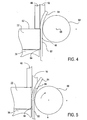
- follower 24 may include a flexible layer or strip 86 and a moveable member that applies a force against strip 86 so as to urge the strip against the boule (see FIGS. 4-5 ).
- the moveable member may be of any suitable type, such as a rotatable roller 88, as shown in FIGS. 4-5 , or a sliding block 90, as shown in FIGS. 6-7 and described below.
- Roller 88 is pivotably coupled to the lower end of shaft 62, for example by pin 60, and may be rotatably actuated by friction against strip 86, for example with some rough coating or small gearing between roller 88 and strip 86, so that the roller 88 rotates in a clockwise direction, in FIGS. 4-5 , about axis 68 as the roller 88 and blade 18 move downward under the force of actuator 20. Roller 88 may also be actuated by a rack and pinion or band drive (not shown).
- Flexible strip 86 may have a first portion 92 adapted to engage the cleaved portion 84 of brittle material, and a second portion 94 adapted to engage blade 18. The first portion 92 has a first thickness and the second portion has a second thickness.
- the first thickness is less than the second thickness by a difference approximating the thickness of the cleaved portion 84.
- roller 88 moves downward and rotates about axis 68 during cleaving, blade 18 advances and roller 88 presses flexible strip 86 to engage boule 22 and blade 18 to control the outward force on the cleaved portion 84 of the brittle material and keep blade 18 aligned for proper cleaving.
- the strip 86 of follower 24 includes a shockwave absorbing layer 96, as shown in FIGS. 6-7 , which can be an elastomeric layer that dampens the shockwaves from each successive crack.
- a shockwave absorbing layer 96 is sandwiched between first and second flexible sheets such as first and second thin steel sheets 98 and 99.
- first sheet 98 is similar to strip 86 illustrated in FIGS. 4-5 and has first and second portions 92 and 94.
- elastomeric layer 96 may be directly engage boule 22, if the elastomer is sufficiently firm, in which case the elastomeric layer is preferably formed with first and second portions 92 and 94.
- a sliding block 90 may be used to apply a force against flexible strip 86 (see FIGS. 6-7 ). Sliding block 90 moves down as blade 18 descends and is preferably coupled to the lower end of shaft 62 and more preferably rigidly secured to the lower end of the shaft 62.
- a bearing surface 91 may be provided on block 90 and be formed of a low coefficient of friction plastic for slidably engaging flexible strip 86. Alternatively, a fluid bearing or other commonly used flat bearing, or any other suitable means, may be used for forming the bearing surface 91 of the block 90.
- rod clamp 38 is raised to allow a boule of brittle material 22 to be pushed or moved by a pushing mechanism such as a pushrod 28 to a desired position for cleaving.
- This pushing may be guided by front and rear boule guides 30 and 32.
- the position of boule 22 can be adjusted by fine adjustment slide 36.
- boule 22 is in a position to be cleaved, its end surface 26 is pushed against follower 24 to an appropriate position relative to blade 18 so as to establish a desired cut depth, that is a desired thickness of the portion of the boule to be cleaved.
- Rod clamp motor 40 is then actuated so that rod clamp 38 engages the boule 22 and retains the boule in the desired position for cleaving. If some space between boule 22 and follower 26 is needed or desired to allow for cleavage, fine adjustment slide 36 can be moved back (away from blade 18) to allow for this space. The length and flexibility of rod clamp pushrod 38 allows boule 22 to remain firmly clamped.
- Cleave actuator 20 is actuated and drives down blade 18 until a crack is initiated. This may be observable by the force on the blade slacking off. Fine adjustment slide 36 is then moved further back, to allow for the back of blade 18 to travel along the incipient cleave. Blade 18 is now advanced further. As the blade 18 advances, follower adjustment assembly 64 moves downward as well, which moves follower shaft 62 down, rotating the follower on pin 60 by any means described above, thus rotating follower 24.
- the slice may be removed by one of two methods. From above, an affordance such as vacuum tweezers can be used to grasp the slice. Fine adjustment slide 36 moves further back to release the slice, and the slice is withdrawn. From beneath, blade 18 is retracted, then fine adjustment slide moves 36 further back, and the slice is released. A combination of these techniques, or other removal techniques, may also be used.
- the present invention provides a method of cleaving a bar of brittle materials.
- the method comprises initiating a crack in the bar and driving a blade through the bar to remove a portion of the brittle material from the end of the bar.
- FIG. 8 A cleaving process where blade 18 cleaves a bar of brittle material 22 according to an embodiment of the present invention is illustrated in FIG. 8 .
- cleaving blade 18 impacts the brittle material at a crystal plane, preferably a weak crystal plane.
- a crystal plane preferably a weak crystal plane.
- the (111) plane is the weakest, with the (110) plane nearly as good.
- the cleaving proceeds through the brittle material at a controlled speed. Rapid crack propagation may deviate from the intended fracture plane, typically resulting in a series of small, incremental cracks.
- Cleaving blade 18 should be hard enough, strong enough, and shaped appropriately to peel the intended sheet of material from the bar of the material.
- the back side or surface 19 of blade 18 facing the main portion of bar 22 is substantially perpendicular to the plane of cleavage, which is parallel to top surface 52 of the boule, so there is little or no force acting on the blade to push it into the slice being cleaved.
- the other side or opposite surface 21 of the blade is, in preferred embodiments, angled enough to be strong enough to withstand the forces, but not too much or the slice being cleaved experiences excessive bending and breaks.
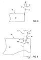
- a groove 100 is formed in bar 22 to be cleaved, as shown in FIG. 9 .
- Groove 100 can be used to position blade 18 so a crack can form under surface 19 of blade 18 facing the bulk of the brittle material, preventing or minimizing outward bending of the blade, which may cause the cleave to diverge and ruin the slice.
- the starting groove also lessens the pressure on the very tip of the blade, reducing the strength requirements and increasing blade (sharpness) lifetime.
- the starting groove can be formed from a vertical surface 101 facing the end of the bar being cleaved and a slanted surface 103 facing the bulk of the bar. It may take the form of a sharp notch, a V-shape, or a "keyhole” notch.
- the "keyhole" notch 100 shown in FIG. 9 has an enlarged bottom or relief 102 so the crack starts under the vertical side.
- the sharp notch 105 shown in FIG. 10 relies on stress concentration at the sharp point of the notch to start the crack under the vertical side.
- the notches of the present invention may be mechanically, chemically or otherwise created.
- the desired shape of the starting grooves can be created either by a diamond tool or by reactive ion etching.
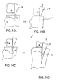
- FIGS. 11A-11B An embodiment of the present invention where blade 18 is adjusted after a crack 107 is initiated in bar 22 is illustrated in FIGS. 11A-11B .
- blade 18 has a symmetric V-shape that is used to maximize the strength of the blade for starting the crack. After the crack is created, blade 18 is leaned or tilted towards the end of bar 22, as shown in FIG. 11B , so that the blade surface 19 facing the bulk of brittle material is parallel to the rod surface 26.
- grooves 100 formed in bar 22 are spaced 50 to 100 microns apart.
- the starting groove 100 is aligned under blade 18.and the bar 22 is then clamped in place. Force is thereafter applied to blade 18.
- the cleaved slice separates, it is picked up in any suitable manner, for example in some embodiments by a suction wand or gas jets. The process is repeated until bar 22 is too short to support further cleaving. Another bar can then be positioned for cleaving.
- FIG. 12 An embodiment of the present invention where a follower 24 engages the end 26 of bar 22 to limit outward force on the cleaved part of slice is illustrated in FIG. 12 .
- the roller 88 supports the cleaved material at the point of cleaving to limit force away from the body of bar 22 and to assist in preventing the slice from cracking or breaking.
- a physical support or backing plate 48 is used for guiding blade 18 (see FIGS. 13A-13D .
- backing plate 48 may include a depending lip 104 that extends into the groove 100, that is preferably V-shaped, to provide a temporary vertical surface 106.
- the temporary vertical surface 106 aligns blade 18 with the sharp point forming the bottom of the V-shaped grooves 100.
- Backing plate 48 supports the blade 18 when blade 18 descends.
- corrosive agents can be applied to the groove and/or crack that preferentially breaks the strained bonds of brittle material.
- corrosive agents can be used to reduce the force required and to allow the crack speed to be limited to much less than the speed of sound, resulting in more controllable cracks.
- Any suitable corrosive agents can be used.
- potassium hydroxide (KOH) solution can be used as a corrosive agent for silicon.
- an electrochemical action can be used to break the strain bonds of brittle material. This can be accomplished with a conductive layer embedded in the blade.
- the position of blade 18 may be adjusted or shifted after a crack is initiated.
- a crack may be formed along a line 110 different from the imaginery line 112 extending downwardly into the bar 22 under the vertical surface of blade 18. After the crack is created and the blade penetrates the bar 22, blade 18 can be shifted slightly toward the slice as shown in the transition between FIG. 14B to FIG. 14C so that when it continues its downward path, blade 18 does not press outwards.
- the present invention has been described with various methods where a thin section of brittle material is cleaved starting from one end of a bar of brittle material. It will be appreciated that the present invention also applies to cleaving by halves, in which a rod is successively cleaved in halves along a path perpendicular to a longitudinal axis 21 of the boule 22 (see FIG. 1 ). As the halves get very thin, they are too weak to support cleaving by conventional means. A first follower can be used to engage one end surface of the thin halve and a second follower can be used to engage the opposite end of the thin halve.
- the blade, follower, and grooves as described above are equally applicable in the latter stages of cleaving in halves, enabling much thinner sections than achievable solely with conventional cleaving.
- An apparatus for use in the method of the present invention for cleaving a section of a bar of brittle material having an end can be provided and include a support adapted to hold the section of the bar in a position to be cleaved, a blade, an actuator coupled to the blade for driving the blade through the bar to create a cleaved portion of the bar and a follower for engaging the end of the bar during cleaving.
- the blade can have a leading edge and a concave curved surface extending away from the leading edge.
- the concave curved surface of the blade can be provided with a curve and the follower can have a convex curved surface provided with a curve approximating the curve of the concave curved surface of the blade.
- the follower can have an additional convex curved surface, and a radially extending surface can extend from the first-named convex curved surface to the additional convex curved surface.
- the cleaved portion of the bar can have a thickness and the first-named convex curved surface can have a first radius and the additional convex curved surface can have a second radius that is less than the first radius by a difference approximating the thickness of the cleaved portion of the bar.
- the cleaved portion of the bar can have a thickness
- the follower can include a movable member and at least one layer of material secured to the movable member, the at least one layer of material having a first portion provided with a first thickness and a second portion provided with a second thickness that is less than the first thickness by a difference approximating the thickness of the cleaved portion of the bar.
- the movable member can have a member rotatable about an axis of rotation.
- the actuator can drive the blade in a direction of travel, and the movable member can be a member translatable in a direction parallel to the direction of travel of the blade.
- the at least one layer of material can include an elastomeric layer.
- the end of the bar can have a planar surface extending transversely of the bar, and the follower can include a planar surface extending from the convex curved surface and parallel to the planar surface of the end of the bar.
- An alternative apparatus for use in the method of the present invention for cleaving a section of a bar of brittle material can be provided and include a support adapted to hold the section of the bar in a position to be cleaved, a blade having a leading edge and a concave region extending away from the leading edge and an actuator coupled to the blade for driving the blade through the bar to create a cleaved portion of the bar.
- the concave region can be formed from a concave curved surface.
- a further cleaving apparatus can be provided and include a bar of brittle material having a section to be cleaved, a support for holding the section of the bar in a position to be cleaved, a blade and an actuator coupled to the blade for driving the blade through the bar to create a cleaved portion of the bar.
- a follower for engaging the end of the bar during cleaving can be included.
- a method of cleaving a bar of brittle material having an end can be provided an include initiating a crack in the bar and driving a blade through the bar to remove a portion of the brittle material from the end of the bar.
- the driving step can include driving the blade through the bar at a controlled speed.
- the initiating step can include initiating the crack a distance ranging from 50 to 200 microns from the end of the bar.
- the brittle material can include a crystalline material.
- the brittle material can be selected from the group of materials consisting of silicon, gallium arsenide, germanium, silicon-germanium and sapphire.
- the initiating step can include driving the blade into the bar of brittle material.
- the method further includes guiding the blade along a physical support prior to driving the blade into the bar to initiate the crack.
- the method can further include aligning the blade with the crack prior to driving the blade along the crack.
- the method further include forming a groove in a surface of the bar prior to the initiating step.
- the forming step can include forming the groove along a crystal plane of the brittle material.
- the groove can be provided with a surface extending substantially perpendicular to a surface of the bar.
- the groove can be a keyhole groove.
- the method can further include guiding the blade along a physical support, at least a portion of the physical support extending into the groove to provide a guiding surface substantially perpendicular to a surface of the bar.
- the method can further include applying a force against the end of the bar.
- the applying step can include moving a follower member along the end of the bar.
- One of the advantages of the method provided by the present invention is that brittle materials can be cleaved into thin sections without saw waste.
Landscapes
- Engineering & Computer Science (AREA)
- Mechanical Engineering (AREA)
- Mining & Mineral Resources (AREA)
- Physics & Mathematics (AREA)
- Condensed Matter Physics & Semiconductors (AREA)
- General Physics & Mathematics (AREA)
- Manufacturing & Machinery (AREA)
- Computer Hardware Design (AREA)
- Microelectronics & Electronic Packaging (AREA)
- Power Engineering (AREA)
- Processing Of Stones Or Stones Resemblance Materials (AREA)
- Processing Of Solid Wastes (AREA)
- Organic Low-Molecular-Weight Compounds And Preparation Thereof (AREA)
- Mechanical Treatment Of Semiconductor (AREA)
- Dicing (AREA)
Applications Claiming Priority (3)
| Application Number | Priority Date | Filing Date | Title |
|---|---|---|---|
| US57688804P | 2004-06-03 | 2004-06-03 | |
| US11/144,465 US7422963B2 (en) | 2004-06-03 | 2005-06-02 | Method for cleaving brittle materials |
| PCT/US2005/019370 WO2005122243A2 (en) | 2004-06-03 | 2005-06-03 | Method and apparatus for cleaving brittle materials |
Publications (3)
| Publication Number | Publication Date |
|---|---|
| EP1782465A2 EP1782465A2 (en) | 2007-05-09 |
| EP1782465A4 EP1782465A4 (en) | 2007-11-28 |
| EP1782465B1 true EP1782465B1 (en) | 2010-03-17 |
Family
ID=35503819
Family Applications (1)
| Application Number | Title | Priority Date | Filing Date |
|---|---|---|---|
| EP20050769112 Expired - Lifetime EP1782465B1 (en) | 2004-06-03 | 2005-06-03 | Method for cleaving brittle materials |
Country Status (13)
Families Citing this family (11)
| Publication number | Priority date | Publication date | Assignee | Title |
|---|---|---|---|---|
| JP4346598B2 (ja) * | 2005-10-06 | 2009-10-21 | 株式会社東芝 | 化合物半導体素子及びその製造方法 |
| JP2007160537A (ja) * | 2005-12-09 | 2007-06-28 | Japan Science & Technology Agency | 劈開方法および劈開装置 |
| WO2007087354A2 (en) | 2006-01-24 | 2007-08-02 | Baer Stephen C | Cleaving wafers from silicon crystals |
| DE102007018080B3 (de) * | 2007-04-17 | 2008-06-19 | Eisele, Christopher, Dr. | Verfahren und Vorrichtung zur Herstellung von dünnen Scheiben oder Folien aus Halbleiterkörpern |
| EP2220477B1 (en) * | 2007-12-18 | 2011-09-21 | CaridianBCT, Inc. | Blood processing apparatus with sealed diffuser in optical control apparatus |
| TWI498990B (zh) * | 2012-12-19 | 2015-09-01 | Genesis Photonics Inc | 劈裂裝置 |
| CN104210039B (zh) * | 2013-05-30 | 2016-04-06 | 正达国际光电股份有限公司 | 钻石线切割机及该钻石线切割机的切割方法 |
| JP6661204B1 (ja) * | 2019-04-19 | 2020-03-11 | ハイソル株式会社 | 層状物質劈開方法 |
| CN111730771B (zh) * | 2020-06-09 | 2021-10-29 | 安徽利锋机械科技有限公司 | 一种晶圆切割机 |
| US11377758B2 (en) | 2020-11-23 | 2022-07-05 | Stephen C. Baer | Cleaving thin wafers from crystals |
| CN114999958B (zh) * | 2022-05-27 | 2024-05-03 | 颀中科技(苏州)有限公司 | 用于去除卷带芯片的芯片剔除装置 |
Family Cites Families (18)
| Publication number | Priority date | Publication date | Assignee | Title |
|---|---|---|---|---|
| US3901423A (en) * | 1973-11-26 | 1975-08-26 | Purdue Research Foundation | Method for fracturing crystalline materials |
| US4184472A (en) * | 1978-05-15 | 1980-01-22 | The United States Of America As Represented By The Administrator Of The National Aeronautics And Space Administration | Method and apparatus for slicing crystals |
| US4244348A (en) * | 1979-09-10 | 1981-01-13 | Atlantic Richfield Company | Process for cleaving crystalline materials |
| US4343287A (en) * | 1980-08-29 | 1982-08-10 | The United States Of America As Represented By The Administrator Of The National Aeronautics And Space Administration | Crystal cleaving machine |
| US4628151A (en) * | 1985-12-30 | 1986-12-09 | Cardas George F | Multi-strand conductor cable having its strands sized according to the golden section |
| JPS62188325A (ja) * | 1986-02-14 | 1987-08-17 | Sumitomo Electric Ind Ltd | 化合物半導体のof面出し方法及び装置 |
| US4955357A (en) * | 1988-01-22 | 1990-09-11 | Hi-Silicon Co., Ltd. | Method and apparatus for cutting polycrystalline silicon rods |
| US6007916A (en) * | 1989-04-06 | 1999-12-28 | Sumitomo Electric Industries, Ltd. | Synthetic single crystal diamond for wiring drawing dies and process for producing the same |
| US5593815A (en) * | 1989-07-31 | 1997-01-14 | Goldstar Co., Ltd. | Cleaving process in manufacturing a semiconductor laser |
| US4980517A (en) * | 1989-09-25 | 1990-12-25 | Tp Orthodontics, Inc. | Multi-strand electrical cable |
| JPH03142928A (ja) * | 1989-10-30 | 1991-06-18 | Disco Abrasive Syst Ltd | ウエーハの切り出し方法 |
| JPH0695504B2 (ja) * | 1989-10-31 | 1994-11-24 | 直江津電子工業株式会社 | ウエハ枚葉式内周刃2分割切断装置におけるウエハ供給回収装置 |
| US5335282A (en) * | 1992-07-22 | 1994-08-02 | Cardas George F | Signal summing non-microphonic differential microphone |
| JP2564084B2 (ja) * | 1993-03-04 | 1996-12-18 | 直江津電子工業株式会社 | 半導体ウエハの回収方法 |
| JPH08298251A (ja) * | 1995-02-28 | 1996-11-12 | Shin Etsu Handotai Co Ltd | 薄板の製造方法 |
| JPH1179770A (ja) * | 1997-07-10 | 1999-03-23 | Yamaha Corp | スクライブ装置及び劈開方法 |
| JPH11284278A (ja) * | 1998-03-27 | 1999-10-15 | Toshiba Corp | レーザダイオードの製造装置および製造方法 |
| JP3733091B2 (ja) * | 2002-08-02 | 2006-01-11 | 直江津電子工業株式会社 | 半導体ウエハ分離装置 |
-
2005
- 2005-06-02 TW TW94118177A patent/TWI402150B/zh not_active IP Right Cessation
- 2005-06-02 US US11/144,465 patent/US7422963B2/en not_active Expired - Lifetime
- 2005-06-03 JP JP2007515564A patent/JP5097543B2/ja not_active Expired - Fee Related
- 2005-06-03 KR KR1020077000136A patent/KR101166595B1/ko not_active Expired - Fee Related
- 2005-06-03 DE DE200560020023 patent/DE602005020023D1/de not_active Expired - Lifetime
- 2005-06-03 MY MYPI20052549A patent/MY142564A/en unknown
- 2005-06-03 BR BRPI0511794-1A patent/BRPI0511794B1/pt not_active IP Right Cessation
- 2005-06-03 AT AT05769112T patent/ATE461021T1/de not_active IP Right Cessation
- 2005-06-03 CA CA2569376A patent/CA2569376C/en not_active Expired - Fee Related
- 2005-06-03 AU AU2005253577A patent/AU2005253577B2/en not_active Ceased
- 2005-06-03 WO PCT/US2005/019370 patent/WO2005122243A2/en active Application Filing
- 2005-06-03 EP EP20050769112 patent/EP1782465B1/en not_active Expired - Lifetime
- 2005-06-03 ES ES05769112T patent/ES2340402T3/es not_active Expired - Lifetime
Also Published As
| Publication number | Publication date |
|---|---|
| CA2569376A1 (en) | 2005-12-22 |
| ES2340402T3 (es) | 2010-06-02 |
| EP1782465A4 (en) | 2007-11-28 |
| BRPI0511794B1 (pt) | 2018-04-03 |
| KR20070044428A (ko) | 2007-04-27 |
| EP1782465A2 (en) | 2007-05-09 |
| WO2005122243A3 (en) | 2007-04-19 |
| HK1102277A1 (en) | 2007-11-09 |
| JP5097543B2 (ja) | 2012-12-12 |
| US7422963B2 (en) | 2008-09-09 |
| BRPI0511794A (pt) | 2008-01-15 |
| TWI402150B (zh) | 2013-07-21 |
| US20050287768A1 (en) | 2005-12-29 |
| KR101166595B1 (ko) | 2012-07-18 |
| AU2005253577A1 (en) | 2005-12-22 |
| DE602005020023D1 (de) | 2010-04-29 |
| WO2005122243A2 (en) | 2005-12-22 |
| AU2005253577B2 (en) | 2011-04-07 |
| JP2008502153A (ja) | 2008-01-24 |
| CA2569376C (en) | 2014-03-04 |
| MY142564A (en) | 2010-12-15 |
| TW200602175A (en) | 2006-01-16 |
| ATE461021T1 (de) | 2010-04-15 |
Similar Documents
| Publication | Publication Date | Title |
|---|---|---|
| EP1782465B1 (en) | Method for cleaving brittle materials | |
| US4227348A (en) | Method of slicing a wafer | |
| EP2633936A1 (en) | Holding device | |
| EP2279983A2 (en) | Method and Apparatus for Processing Brittle Material Substrate | |
| US12036700B2 (en) | Dividing device for wafer | |
| KR101896739B1 (ko) | 유리기판 할단장치, 유리기판 할단방법 및 유리기판 제작방법 | |
| KR101212966B1 (ko) | 절단방법 및 그 장치 | |
| JP4602679B2 (ja) | ワイヤ式挽き切り方法及び装置 | |
| CN101267920B (zh) | 劈割脆性材料的方法 | |
| TW201931449A (zh) | 附金屬膜之基板之分斷方法 | |
| KR20000029988A (ko) | 물질을전단하는방법과장치 | |
| WO2020066408A1 (ja) | メタル膜付き基板の分断方法 | |
| EP0951980B1 (en) | Apparatus for cleaving crystals | |
| HK1102277B (en) | Method for cleaving brittle materials | |
| TWI661920B (zh) | 複合基板之分斷方法及分斷裝置 | |
| JP5216524B2 (ja) | 脆性材料プライヤ | |
| WO2025005213A1 (ja) | ブレイク方法、及び、ブレイク装置 | |
| JP2006198836A (ja) | 脆性材料の切断装置、その切断方法及びその切断装置を用いて切断した脆性材料 | |
| WO2025005214A1 (ja) | ブレイク装置、及び、ブレイク方法 | |
| JP2003261345A (ja) | 硬質脆性板の割断方法 | |
| CN119702618A (zh) | 一种破碎刀头及使用该刀头的催化剂板结破碎装置 | |
| KR20210039434A (ko) | 스크라이브 헤드 및 스크라이브 장치 | |
| JP2002337135A (ja) | シリコンインゴットのコーン状端部の切除方法 | |
| KR20110098031A (ko) | 판재 전단 장치 |
Legal Events
| Date | Code | Title | Description |
|---|---|---|---|
| PUAI | Public reference made under article 153(3) epc to a published international application that has entered the european phase |
Free format text: ORIGINAL CODE: 0009012 |
|
| 17P | Request for examination filed |
Effective date: 20061221 |
|
| AK | Designated contracting states |
Kind code of ref document: A2 Designated state(s): AT BE BG CH CY CZ DE DK EE ES FI FR GB GR HU IE IS IT LI LT LU MC NL PL PT RO SE SI SK TR |
|
| AX | Request for extension of the european patent |
Extension state: AL BA HR LV MK YU |
|
| R17D | Deferred search report published (corrected) |
Effective date: 20070419 |
|
| RIC1 | Information provided on ipc code assigned before grant |
Ipc: B26F 3/00 20060101AFI20070530BHEP Ipc: H01L 21/304 20060101ALI20070530BHEP Ipc: H01L 21/463 20060101ALI20070530BHEP |
|
| DAX | Request for extension of the european patent (deleted) | ||
| REG | Reference to a national code |
Ref country code: HK Ref legal event code: DE Ref document number: 1102277 Country of ref document: HK |
|
| A4 | Supplementary search report drawn up and despatched |
Effective date: 20071025 |
|
| RIC1 | Information provided on ipc code assigned before grant |
Ipc: B26F 3/00 20060101AFI20070530BHEP Ipc: H01L 21/463 20060101ALI20071019BHEP Ipc: H01L 21/304 20060101ALI20071019BHEP Ipc: B28D 5/04 20060101ALI20071019BHEP Ipc: B28D 1/22 20060101ALI20071019BHEP |
|
| 17Q | First examination report despatched |
Effective date: 20080407 |
|
| RTI1 | Title (correction) |
Free format text: METHOD FOR CLEAVING BRITTLE MATERIALS |
|
| GRAP | Despatch of communication of intention to grant a patent |
Free format text: ORIGINAL CODE: EPIDOSNIGR1 |
|
| GRAS | Grant fee paid |
Free format text: ORIGINAL CODE: EPIDOSNIGR3 |
|
| GRAA | (expected) grant |
Free format text: ORIGINAL CODE: 0009210 |
|
| AK | Designated contracting states |
Kind code of ref document: B1 Designated state(s): AT BE BG CH CY CZ DE DK EE ES FI FR GB GR HU IE IS IT LI LT LU MC NL PL PT RO SE SI SK TR |
|
| REG | Reference to a national code |
Ref country code: GB Ref legal event code: FG4D |
|
| REG | Reference to a national code |
Ref country code: CH Ref legal event code: EP |
|
| REG | Reference to a national code |
Ref country code: IE Ref legal event code: FG4D |
|
| REF | Corresponds to: |
Ref document number: 602005020023 Country of ref document: DE Date of ref document: 20100429 Kind code of ref document: P |
|
| REG | Reference to a national code |
Ref country code: ES Ref legal event code: FG2A Ref document number: 2340402 Country of ref document: ES Kind code of ref document: T3 |
|
| REG | Reference to a national code |
Ref country code: NL Ref legal event code: VDEP Effective date: 20100317 |
|
| PG25 | Lapsed in a contracting state [announced via postgrant information from national office to epo] |
Ref country code: LT Free format text: LAPSE BECAUSE OF FAILURE TO SUBMIT A TRANSLATION OF THE DESCRIPTION OR TO PAY THE FEE WITHIN THE PRESCRIBED TIME-LIMIT Effective date: 20100317 |
|
| LTIE | Lt: invalidation of european patent or patent extension |
Effective date: 20100317 |
|
| PG25 | Lapsed in a contracting state [announced via postgrant information from national office to epo] |
Ref country code: SI Free format text: LAPSE BECAUSE OF FAILURE TO SUBMIT A TRANSLATION OF THE DESCRIPTION OR TO PAY THE FEE WITHIN THE PRESCRIBED TIME-LIMIT Effective date: 20100317 Ref country code: FI Free format text: LAPSE BECAUSE OF FAILURE TO SUBMIT A TRANSLATION OF THE DESCRIPTION OR TO PAY THE FEE WITHIN THE PRESCRIBED TIME-LIMIT Effective date: 20100317 Ref country code: AT Free format text: LAPSE BECAUSE OF FAILURE TO SUBMIT A TRANSLATION OF THE DESCRIPTION OR TO PAY THE FEE WITHIN THE PRESCRIBED TIME-LIMIT Effective date: 20100317 Ref country code: PL Free format text: LAPSE BECAUSE OF FAILURE TO SUBMIT A TRANSLATION OF THE DESCRIPTION OR TO PAY THE FEE WITHIN THE PRESCRIBED TIME-LIMIT Effective date: 20100317 |
|
| REG | Reference to a national code |
Ref country code: HK Ref legal event code: GR Ref document number: 1102277 Country of ref document: HK |
|
| PG25 | Lapsed in a contracting state [announced via postgrant information from national office to epo] |
Ref country code: NL Free format text: LAPSE BECAUSE OF FAILURE TO SUBMIT A TRANSLATION OF THE DESCRIPTION OR TO PAY THE FEE WITHIN THE PRESCRIBED TIME-LIMIT Effective date: 20100317 Ref country code: RO Free format text: LAPSE BECAUSE OF FAILURE TO SUBMIT A TRANSLATION OF THE DESCRIPTION OR TO PAY THE FEE WITHIN THE PRESCRIBED TIME-LIMIT Effective date: 20100317 Ref country code: SE Free format text: LAPSE BECAUSE OF FAILURE TO SUBMIT A TRANSLATION OF THE DESCRIPTION OR TO PAY THE FEE WITHIN THE PRESCRIBED TIME-LIMIT Effective date: 20100317 Ref country code: CY Free format text: LAPSE BECAUSE OF FAILURE TO SUBMIT A TRANSLATION OF THE DESCRIPTION OR TO PAY THE FEE WITHIN THE PRESCRIBED TIME-LIMIT Effective date: 20100317 Ref country code: GR Free format text: LAPSE BECAUSE OF FAILURE TO SUBMIT A TRANSLATION OF THE DESCRIPTION OR TO PAY THE FEE WITHIN THE PRESCRIBED TIME-LIMIT Effective date: 20100618 Ref country code: EE Free format text: LAPSE BECAUSE OF FAILURE TO SUBMIT A TRANSLATION OF THE DESCRIPTION OR TO PAY THE FEE WITHIN THE PRESCRIBED TIME-LIMIT Effective date: 20100317 Ref country code: BE Free format text: LAPSE BECAUSE OF FAILURE TO SUBMIT A TRANSLATION OF THE DESCRIPTION OR TO PAY THE FEE WITHIN THE PRESCRIBED TIME-LIMIT Effective date: 20100317 |
|
| PG25 | Lapsed in a contracting state [announced via postgrant information from national office to epo] |
Ref country code: SK Free format text: LAPSE BECAUSE OF FAILURE TO SUBMIT A TRANSLATION OF THE DESCRIPTION OR TO PAY THE FEE WITHIN THE PRESCRIBED TIME-LIMIT Effective date: 20100317 Ref country code: CZ Free format text: LAPSE BECAUSE OF FAILURE TO SUBMIT A TRANSLATION OF THE DESCRIPTION OR TO PAY THE FEE WITHIN THE PRESCRIBED TIME-LIMIT Effective date: 20100317 Ref country code: IS Free format text: LAPSE BECAUSE OF FAILURE TO SUBMIT A TRANSLATION OF THE DESCRIPTION OR TO PAY THE FEE WITHIN THE PRESCRIBED TIME-LIMIT Effective date: 20100717 Ref country code: BG Free format text: LAPSE BECAUSE OF FAILURE TO SUBMIT A TRANSLATION OF THE DESCRIPTION OR TO PAY THE FEE WITHIN THE PRESCRIBED TIME-LIMIT Effective date: 20100617 |
|
| PLBE | No opposition filed within time limit |
Free format text: ORIGINAL CODE: 0009261 |
|
| STAA | Information on the status of an ep patent application or granted ep patent |
Free format text: STATUS: NO OPPOSITION FILED WITHIN TIME LIMIT |
|
| PG25 | Lapsed in a contracting state [announced via postgrant information from national office to epo] |
Ref country code: DK Free format text: LAPSE BECAUSE OF FAILURE TO SUBMIT A TRANSLATION OF THE DESCRIPTION OR TO PAY THE FEE WITHIN THE PRESCRIBED TIME-LIMIT Effective date: 20100317 Ref country code: PT Free format text: LAPSE BECAUSE OF FAILURE TO SUBMIT A TRANSLATION OF THE DESCRIPTION OR TO PAY THE FEE WITHIN THE PRESCRIBED TIME-LIMIT Effective date: 20100719 Ref country code: MC Free format text: LAPSE BECAUSE OF NON-PAYMENT OF DUE FEES Effective date: 20100630 |
|
| REG | Reference to a national code |
Ref country code: CH Ref legal event code: PL |
|
| 26N | No opposition filed |
Effective date: 20101220 |
|
| PG25 | Lapsed in a contracting state [announced via postgrant information from national office to epo] |
Ref country code: IT Free format text: LAPSE BECAUSE OF FAILURE TO SUBMIT A TRANSLATION OF THE DESCRIPTION OR TO PAY THE FEE WITHIN THE PRESCRIBED TIME-LIMIT Effective date: 20100317 |
|
| PG25 | Lapsed in a contracting state [announced via postgrant information from national office to epo] |
Ref country code: CH Free format text: LAPSE BECAUSE OF NON-PAYMENT OF DUE FEES Effective date: 20100630 Ref country code: LI Free format text: LAPSE BECAUSE OF NON-PAYMENT OF DUE FEES Effective date: 20100630 Ref country code: IE Free format text: LAPSE BECAUSE OF NON-PAYMENT OF DUE FEES Effective date: 20100603 |
|
| PG25 | Lapsed in a contracting state [announced via postgrant information from national office to epo] |
Ref country code: LU Free format text: LAPSE BECAUSE OF NON-PAYMENT OF DUE FEES Effective date: 20100603 Ref country code: HU Free format text: LAPSE BECAUSE OF FAILURE TO SUBMIT A TRANSLATION OF THE DESCRIPTION OR TO PAY THE FEE WITHIN THE PRESCRIBED TIME-LIMIT Effective date: 20100918 |
|
| PG25 | Lapsed in a contracting state [announced via postgrant information from national office to epo] |
Ref country code: TR Free format text: LAPSE BECAUSE OF FAILURE TO SUBMIT A TRANSLATION OF THE DESCRIPTION OR TO PAY THE FEE WITHIN THE PRESCRIBED TIME-LIMIT Effective date: 20100317 |
|
| REG | Reference to a national code |
Ref country code: FR Ref legal event code: PLFP Year of fee payment: 12 |
|
| REG | Reference to a national code |
Ref country code: FR Ref legal event code: PLFP Year of fee payment: 13 |
|
| REG | Reference to a national code |
Ref country code: FR Ref legal event code: PLFP Year of fee payment: 14 |
|
| PGFP | Annual fee paid to national office [announced via postgrant information from national office to epo] |
Ref country code: DE Payment date: 20200909 Year of fee payment: 16 Ref country code: ES Payment date: 20200925 Year of fee payment: 16 Ref country code: FR Payment date: 20200914 Year of fee payment: 16 Ref country code: GB Payment date: 20200909 Year of fee payment: 16 |
|
| REG | Reference to a national code |
Ref country code: DE Ref legal event code: R119 Ref document number: 602005020023 Country of ref document: DE |
|
| GBPC | Gb: european patent ceased through non-payment of renewal fee |
Effective date: 20210603 |
|
| PG25 | Lapsed in a contracting state [announced via postgrant information from national office to epo] |
Ref country code: GB Free format text: LAPSE BECAUSE OF NON-PAYMENT OF DUE FEES Effective date: 20210603 Ref country code: DE Free format text: LAPSE BECAUSE OF NON-PAYMENT OF DUE FEES Effective date: 20220101 |
|
| PG25 | Lapsed in a contracting state [announced via postgrant information from national office to epo] |
Ref country code: FR Free format text: LAPSE BECAUSE OF NON-PAYMENT OF DUE FEES Effective date: 20210630 |
|
| REG | Reference to a national code |
Ref country code: ES Ref legal event code: FD2A Effective date: 20220801 |
|
| PG25 | Lapsed in a contracting state [announced via postgrant information from national office to epo] |
Ref country code: ES Free format text: LAPSE BECAUSE OF NON-PAYMENT OF DUE FEES Effective date: 20210604 |