EP1781522B1 - Aufkletterschutz bei eisenbahnfahrzeugen - Google Patents
Aufkletterschutz bei eisenbahnfahrzeugen Download PDFInfo
- Publication number
- EP1781522B1 EP1781522B1 EP05758984A EP05758984A EP1781522B1 EP 1781522 B1 EP1781522 B1 EP 1781522B1 EP 05758984 A EP05758984 A EP 05758984A EP 05758984 A EP05758984 A EP 05758984A EP 1781522 B1 EP1781522 B1 EP 1781522B1
- Authority
- EP
- European Patent Office
- Prior art keywords
- aks
- sch
- aae
- rail vehicle
- aps
- Prior art date
- Legal status (The legal status is an assumption and is not a legal conclusion. Google has not performed a legal analysis and makes no representation as to the accuracy of the status listed.)
- Expired - Lifetime
Links
Images


Classifications
-
- B—PERFORMING OPERATIONS; TRANSPORTING
- B61—RAILWAYS
- B61D—BODY DETAILS OR KINDS OF RAILWAY VEHICLES
- B61D15/00—Other railway vehicles, e.g. scaffold cars; Adaptations of vehicles for use on railways
- B61D15/06—Buffer cars; Arrangements or construction of railway vehicles for protecting them in case of collisions
-
- B—PERFORMING OPERATIONS; TRANSPORTING
- B61—RAILWAYS
- B61D—BODY DETAILS OR KINDS OF RAILWAY VEHICLES
- B61D17/00—Construction details of vehicle bodies
- B61D17/04—Construction details of vehicle bodies with bodies of metal; with composite, e.g. metal and wood body structures
- B61D17/06—End walls
-
- B—PERFORMING OPERATIONS; TRANSPORTING
- B61—RAILWAYS
- B61F—RAIL VEHICLE SUSPENSIONS, e.g. UNDERFRAMES, BOGIES OR ARRANGEMENTS OF WHEEL AXLES; RAIL VEHICLES FOR USE ON TRACKS OF DIFFERENT WIDTH; PREVENTING DERAILING OF RAIL VEHICLES; WHEEL GUARDS, OBSTRUCTION REMOVERS OR THE LIKE FOR RAIL VEHICLES
- B61F1/00—Underframes
- B61F1/08—Details
- B61F1/10—End constructions
Definitions
- the invention relates to a rail vehicle with a arranged on an end-sideffyend Scheme, extending substantially over the entire vehicle width Aufklettertik.
- anti-limbers In the case of a collision between two rail vehicles, there is a risk that a car body with a certain height offset moves over the other, causing strong destruction in the passenger compartment. In order to prevent this, long anti-climber devices, so-called “anti-limbers”, have already been arranged on frontal vehicle end regions.
- Anticlimber have several parallel and horizontal ribs, which, for example, from the illustrations after Fig. 4 to the prior art.
- railway carriage 1 is at its two ends a substantially extending over the entire car side climbing protection arranged so that in the event of a collision, a force can be introduced into the supporting area of the car.
- the anti-climb protection can be made narrower or interrupted.
- the climbing protection is as in the Fig. 4 over the front wall of the car. He may possibly have a cladding, eg made of glass fiber reinforced plastic, which is destroyed in the event of a collision before the mutual engagement of two Aufkletterschutze.
- the at least one anti-climbing element has ribs which, in the event of a collision with another rail vehicle, can be brought into engagement with ribs of a climbing protection of the other rail vehicle.
- At least one impact column is provided, the longitudinal extension of which extends substantially normal to the rail plane, wherein the anti-climbing element is arranged in the interior of the impact column.
- the at least one impact column may be formed as a thin-walled aluminum hollow chamber profile, in which the at least one anti-climbing element is arranged.
- the Aluhohlcroprofil can be pressed plastically in a collision, thereby enabling intervention in the recesses of the anti-climbing element.
- an advantageous variant of the invention consists in that the at least one impact column is designed as a door pillar of an emergency door.
- an inventive rail vehicle SCH, SCH ' which is preferably a railroad car, at its front ends END, END' Aufklettertike AKS, AKS ', which extend substantially over the entire vehicle width.
- the rail vehicles SCH, SCH ' are coupled to form a train.
- the Aufkletterschutz AKS, AKS ' has in the illustrated embodiment ribs RIP, RIP' on ( Fig. 5 ). These ribs RIP, RIP 'run horizontally and parallel to each other ( Fig. 8 ). Here are three such ribs RIP, RIP 'provided, with their strength may be for example 10 mm.
- the climbing protection AKS, AKS ' consists of a steel or aluminum alloy or another material commonly used in rail vehicles. When the rail vehicles SCH, SCH 'travel up to each other with a slight vertical offset of the rail vehicles SCH, SCH', the climbing protectors AKS, AKS 'can mesh with one another and prevent them from climbing ( Fig. 6 ).
- an anti-climbing element AAE, AAE ' is provided, which partially extends the Aufkletterschutz AKS, AKS' in the vertical direction .
- the anti-climbing elements AAE, AAE ' are engageable with the anti-climb protection AKS, AKS' of another rail vehicle in a collision.
- two block-shaped anti-climbing elements AAE, AAE ' are provided above each anti-climbing protection AKS, AKS'.
- the anti-climbing elements AAE, AAE ' represent functionally an extension of the climbing protection AKS, AKS'.
- the anti-climbing element AAE, AAE ' which may be made of the same material as the climbing protection AKS, AKS', also has ribs RIP ", RIP" ' on.
- the anti-climbing element AAE, AAE 'of a rail vehicle SCH, SCH' is set back in relation to the vehicle longitudinal direction relative to the climbing protection AKS, AKS 'of this rail vehicle SCH, SCH' in the direction of the car body.
- Fig. 7 For example, in the event of a collision, the ribs of the anti-climbing element AAE can be brought into engagement with the ribs of a climbing protection AKS 'of another rail vehicle SCH', whereby according to the invention a climbing of the rail vehicle SCH 'onto the rail vehicle SCH can be prevented.
- the anti-climbing element AAE, AAE ' can be connected to the anti-climbing protection AKS, AK5', for example, welded, or also integrally formed with the anti-climbing AKS, AKS '.
- the anti-climbing element AAE, AAE ' can also be formed as an independent structural element, which is connected to a base UGS of the rail vehicle SCH.
- the Aufkletterelement AAE inside a collision column APS APS 'is arranged, whose longitudinal extent L is substantially normal to the rail plane ( Fig. 8 ).
- the impact column APS may be formed as a thin-walled Aluhohlhuntprofil in which the anti-climbing element AAE is arranged.
- the Aluhohlhuntprofil can be plastically pressed and thus an intervention of the climbing protection AKS 'in the anti-climbing element AAE be possible.
- AKS In order to ensure a good intervention of the climbing protection AKS, AKS 'over the entire width of the vehicle SCH, SCH', preferably at least two anti-climbing elements AAE, AAE 'or impact columns APS, APS' in the front of the vehicle SCH, SCH 'are provided.
- the impact columns APS form pillars of an emergency door arranged in the vehicle front ( Fig. 8 ).
- This embodiment is made possible in particular by the space required for an escape door, since the anti-climbing element AAE does not restrict the available space for the floor level.
Landscapes
- Engineering & Computer Science (AREA)
- Mechanical Engineering (AREA)
- Life Sciences & Earth Sciences (AREA)
- Wood Science & Technology (AREA)
- Transportation (AREA)
- Body Structure For Vehicles (AREA)
- Professional, Industrial, Or Sporting Protective Garments (AREA)
- Details Of Garments (AREA)
- Ropes Or Cables (AREA)
- Electric Propulsion And Braking For Vehicles (AREA)
- Control Of Ac Motors In General (AREA)
- Control Of Vehicles With Linear Motors And Vehicles That Are Magnetically Levitated (AREA)
- Vehicle Interior And Exterior Ornaments, Soundproofing, And Insulation (AREA)
- Vibration Dampers (AREA)
Description
- Die Erfindung betrifft ein Schienenfahrzeug mit einem an einem stirnseitigen Fahrzeugendbereich angeordneten, im wesentlichen über die gesamte Fahrzeugbreite verlaufenden Aufkletterschutz.
- Im Fall eines Auffahrunfalls zwischen zwei Schienenfahrzeugen besteht die Gefahr, dass sich ein Wagenkasten mit einem gewissen Höhenversatz über den anderen schiebt und dadurch starke Zerstörungen im Fahrgastraum bewirkt. Um das zu verhindern werden an stirnseitigen Fahrzeugendbereichen schon lange Aufkletterschutzvorrichtungen, sogenannte "Anticlimber" angeordnet.
- Ein Aufkletterschutz der eingangs genannten Art, ist beispielsweise aus der
EP 1 006 034 A1 bekannt geworden ist. - Üblicherweise besitzen Anticlimber mehrere parallele und horizontale Rippen, was beispielsweise aus den Darstellungen nach
Fig. 4 zum Stand der Technik hervorgeht. Bei dem teilweise dargestellten Eisenbahnwagen 1 ist an seinen beiden Enden ein sich im wesentlichen über die gesamte Wagenseite erstreckender Aufkletterschutz so angeordnet, dass im Kollisionsfall eine Krafteinleitung in den tragenden Bereich des Wagens erfolgen kann. Im Bereich der Kupplung kann der Aufkletterschutz schmäler ausgeführt oder unterbrochen sein. Der Aufkletterschutz steht wie gemäß derFig. 4 über die Stirnwand des Wagens vor. Er kann gegebenenfalls eine Verkleidung, z.B. aus glasfaserverstärktem Kunststoff besitzen, die im Kollisionsfall vor dem gegenseitigen Eingriff zweier Aufkletterschutze zerstört wird. - Bekannte Aufkletterschutze stehen fast immer in Konkurrenz mit der Kupplung, denn wenn Kupplungshöhe und die Höhe des Wagenbodens festgelegt sind, bleibt unter Berücksichtigung der Kupplungsbewegungen meist wenig Platz für einen Aufkletterschutz. Dies zeigt z.B. der Artikel "Herstellung von Schienenfahrzeugen" in ZEV + DET Glas. Ann.123 (1999). Die für den Anticlimber verbleibende Einbauhöhe ist in vielen Fällen für einen durchgehen den Anticlimber zu gering. Siehe ebenfalls die
EP 1394009 A1 . - Ein Problem muss darin gesehen werden, dass die Bauhöhe der Aufkletterschutze, wie oben erwähnt, wegen der Kupplung beschränkt ist, man aber andererseits nicht davon ausgehen kann, dass sich bei einem Unfall die Aufkletterschutze zweier kollidierender Wagen genau auf gleicher Höhe befinden.
- Die Folge des genannten Problems ist entweder ein völliges Versagen des Aufkletterschutzes oder eine undefinierte Kräfteeinleitung unter zumindest teilweiser Umgehung der in Eisenbahnwagen üblicherweise eingebauten Stoßverzehrelemente.
- Es ist daher eine Aufgabe der Erfindung, ein Schienenfahrzeug zu schaffen, bei welchem die oben genannten Nachteile so weit wie möglich beseitigt sind.
- Diese Aufgabe wird durch die Merkmale des Anspruchs 1 gelöst, mit einem Schienenfahrzeug das an dem stirnseitigen Fahrzeugendbereich des Schienenfahrzeuges zumindest ein den Aufkletterschutz in vertikaler Richtung teilweise verlängerndes Antiaufkletterelement angeordnet ist, welches mit dem Aufkletterschutz eines anderen Schienenfahrzeuges bei einem Zusammenstoß in Eingriff bringbar ist.
- Es ist ein Verdienst der Erfindung, dass die Krafteinleitung bei einem Zusammenstoß zweier Schienenfahrzeuge in den durch das Antiaufkletterelement erhöhten Greifbereich erfolgt und somit genau zu erfassen ist. Weiters ist es von Vorteil, dass der Platz oberhalb der Kupplung weitgehend frei bleibt. Somit steht Dank der erfindungsgemäßen Lösung mehr Platz für die Kupplung samt Druckluft und Elektrik zur Verfügung.
- Gemäß der Erfindung weist das zumindest eine Antiaufkletterelement Rippen auf, die im Fall einer Kollision mit einem anderen Schienenfahrzeug mit Rippen eines Aufkletterschutz des anderen Schienenfahrzeuges in Eingriff bringbar sind.
- Des weiteren ist zumindest eine Aufprallsäule vorgesehen ist, deren Längserstreckung im wesentlichen normal zur Schienenebene verläuft, wobei das Antiaufkletterelement im Inneren der Aufprallsäule angeordnet ist.
- Weiters kann die zumindest eine Aufprallsäule als dünnwandiges Aluhohlkammerprofil ausgebildet sein, in welchem das zumindest eine Antiaufkletterelement angeordnet ist. Das Aluhohlkammerprofil kann bei einer Kollision plastisch eingedrückt werden, wodurch ein Eingreifen in die Vertiefungen des Antiaufkletterelementes zu ermöglichen.
- Da bei der erfindungsgemäßen Lösung bauartbedingt der Platzbedarf für eine Fluchttür gegeben ist, besteht eine vorteilhafte Variante der Erfindung darin, dass die zumindest eine Aufprallsäule als Türsäule einer Nottür ausgebildet ist.
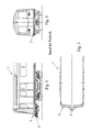
- Die Erfindung samt weiterer Vorteile wird im Folgenden anhand einiger nicht einschränkender Ausführungsbeispiele näher erläutert, welche in der Zeichnung dargestellt sind. In dieser zeigen schematisch:
-
Fig. 4 Endbereiche zweier miteinander kollidierender erfindungsgemäßer Schienenfahrzeuge in einer seitlichen Ansicht; -
Fig. 5 Endbereiche zweier miteinander gekuppelter erfindungsgemäßer Schienenfahrzeuge in einer Normalbetriebsposition; -
Fig. 6 die Endbereiche ausFig. 5 bei einer Kollision mit einem geringen Höhenversatz der beteiligten Schienenfahrzeuge zueinander; -
Fig. 7 die Endbereiche ausFig. 5 und 6 bei einer Kollision mit einem großen Höhenversatz der beteiligten Schienenfahrzeuge zueinander und -
Fig. 8 eine stirnseitige Frontseite eines erfindungsgemäßen Schienenfahrzeuges in perspektivischer Darstellung. - Gemäß
Fig. 4 weist ein erfindungsgemäßes Schienenfahrzeug SCH, SCH', welches bevorzugterweise ein Eisenbahnwaggon ist, an seinen stirnseitigen Enden END, END' Aufkletterschutze AKS, AKS' auf, die im wesentlichen über die gesamte Fahrzeugbreite verlaufen. In einer bevorzugten Variante der Erfindung sind die Schienenfahrzeuge SCH, SCH' zu einem Zugverband gekoppelt. - Der Aufkletterschutz AKS, AKS' weist bei der dargestellten Ausführungsform Rippen RIP, RIP' auf (
Fig. 5 ). Diese Rippen RIP, RIP' verlaufen horizontal und parallel zueinander (Fig. 8 ). Hier sind drei solche Rippen RIP, RIP' vorgesehen, wobei ihre Stärke beispielsweise 10 mm betragen kann. Der Aufkletterschutz AKS, AKS' besteht aus einer Stahl- oder Aluminiwmlegierung oder aus einem anderen, bei Schienenfahrzeugen gebräuchlichen Werkstoff. Bei einem Auffahren der Schienenfahrzeuge SCH, SCH' mit einem geringen Höhenversatz der Schienenfahrzeuge SCH, SCH' zueinander können die Aufkletterschutze AKS, AKS' ineinander greifen und ein Aufklettern verhindern (Fig. 6 ). - Um ein Aufklettern bei einem Zusammenstoss mit einem der großen Höhenversatz der beiden Schienenfahrzeuge SCH, SCH' zueinander zu verhindern, ist über dem Aufkletterschutz AKS, AKS' ein Antiaufkletterelement AAE, AAE' vorgesehen, welches den Aufkletterschutz AKS, AKS' in vertikaler Richtung teilweise verlängert. Die Antiaufkletterelemente AAE, AAE' sind mit dem Aufkletterschutz AKS, AKS' eines anderen Schienenfahrzeuges bei einem Zusammenstoß in Eingriff bringbar. In der hier dargestellten Ausführungsform sind über jedem Aufkletterschutz AKS, AKS' zwei blockförmige Antiaufkletterelemente AAE, AAE' vorgesehen.
- Die Antiaufkletterelemente AAE, AAE' stellen in funktioneller Hinsicht eine Verlängerung des Aufkletterschutzes AKS, AKS' dar. Das Antiaufkletterelement AAE, AAE' welches aus dem gleichen Material wie der Aufkletterschutz AKS, AKS' hergestellt sein kann, weist ebenfalls Rippen RIP", RIP"' auf. Das Antiaufkletterelement AAE, AAE' eines Schienenfahrzeuges SCH, SCH' ist in bezug auf die Fahrzeuglängsrichtung gegenüber dem Aufkletterschutz AKS, AKS' dieses Schienenfahrzeuges SCH, SCH' in Richtung des Wagenkastens zurückversetzt.
- Gemäß
Fig. 7 können die Rippen des Antiaufkletterelementes AAE im Fall einer Kollision mit den Rippen eines Aufkletterschutzes AKS' eines anderen Schienenfahrzeuges SCH' in Eingriff gebracht werden, wodurch erfindungsgemäß ein Aufklettern des Schienenfahrzeuges SCH' auf das Schienenfahrzeug SCH verhindert werden kann. - Das Antiaufkletterelement AAE, AAE' kann mit dem Aufkletterschutz AKS, AK5' verbunden, beispielsweise verschweißt, oder auch einstückig mit dem Aufkletterschutz AKS, AKS' ausgebildet sein. Das Antiaufkletterelement AAE, AAE' kann auch als eigenständiges bauliches Element ausgebildet sein, welches mit einem Untergestell UGS des Schienenfahrzeuges SCH verbunden ist.
- Bei der Erfindung ist das Aufkletterelement AAE im Inneren einer Aufprallsäule APS, APS' angeordnet, deren Längserstreckung L im wesentlichen normal zur Schienenebene verläuft (
Fig. 8 ). Die Aufprallsäule APS kann als dünnwandiges Aluhohlkammerprofil ausgebildet sein, in welchem das Antiaufkletterelement AAE angeordnet ist. Bei einer Kollision kann das Aluhohlkammerprofil plastisch eingedrückt und somit ein Eingreifen des Aufkletterschutzes AKS' in das Antiaufkletterelement AAE ermöglicht werden. - Um ein gutes Eingreifen des Aufkletterschutzes AKS, AKS' über die gesamte Breite des Fahrzeuges SCH, SCH' zu gewährleisten, sind bevorzugterweise mindestens zwei Antiaufkletterelemente AAE, AAE' bzw. Aufprallsäulen APS, APS' in der Front des Fahrzeuges SCH, SCH' vorgesehen.
- Gemäß einer Ausführungsform der Erfindung bilden die Aufprallsäulen APS Säulen einer in der Fahrzeugfront angeordneten Nottür (
Fig. 8 ). Diese Ausführungsform wird insbesondere dadurch ermöglicht, dass der Platzbedarf für eine Fluchttür gegeben ist, da das Antiaufkletterelement AAE nicht den zur Verfügung stehenden Platz für die Fußbodenhöhe einschränkt. - Zusammenfassend lässt sich sagen, dass ein großes Verdienst der Erfindung darin besteht, es auf einfache und kostengünstige Weise zu ermöglichen, einen durchgehenden Aufkletterschutz anzuordnen, ohne in einen Bauraumkonflikt mit der Kupplung zu treten.
Claims (3)
- Schienenfahrzeug (SCH, SCH') mit einem an einem stirnseitigen Fahrzeugmdbereich (END, END) angeordneten im wesentlichen über die gesamte Fahrzeugbreite verlaufenden Aufkletterschutz (AKS, AKS'), bei dem an dem stirnseitigen Fahrzeugendbereich (END, END') des Schienenfahrzeuges (SCH SCH') zumindest ein den Aufkletterschutz (AKS) in vertikaler Richtung teilweise verlängerndes Antiaufkletterelement (AAB, AAE') angeordnet ist, welches mit dem Aufkletterschutz (AKS, AKS') eines anderen Schienenfahrzeuges bei einem Zusammenstoß in Eingriff bringbar ist, bei dem weiterhin das zumindest eine Antiaufkletterelement (AAE, AAE') Rippen aufweist, die im Fall einer Kollision mit einem anderen Schienenfahrzeug (SCH, SCH') mit Rippen eines Aufkletterschutz (AKS, AKS) des anderen Schienenfahrzeuges (SCH, SCH') in Eingriff bringbar sind,
dadurch gekennzeichnet, dass zumindest eine Aufprallsäule (APS, APS') vorgesehen ist, deren Längserstreckung (L) im wesentlichen normal zur Schienenebene verläuft wobei das Antiaufkletterelement (AAB) im Inneren der Aufprallsäule (APS, APS') angeordnet ist. - Schienenfahrzeug nach Anspruch 1, dadurch gekennzeichnet, dass die zumindest eine Aufprallsäule (APS, APS') als dünnwandiges Aluhohlkammerprofil ausgebildet ist.
- Schienenfahrzeug nach einem der Ansprüche 1 bis 2, dadurch gekennzeichnet dass die zumindest eine Aufprallsäule (APS, APS') als Türsäule einer Nottür ausgebildet ist.
Applications Claiming Priority (2)
| Application Number | Priority Date | Filing Date | Title |
|---|---|---|---|
| AT0128904A AT504300B1 (de) | 2004-07-28 | 2004-07-28 | Aufkletterschutz bei eisenbahnfahrzeugen |
| PCT/AT2005/000255 WO2006010176A1 (de) | 2004-07-28 | 2005-07-07 | Aufkletterschutz bei eisenbahnfahrzeugen |
Publications (2)
| Publication Number | Publication Date |
|---|---|
| EP1781522A1 EP1781522A1 (de) | 2007-05-09 |
| EP1781522B1 true EP1781522B1 (de) | 2010-03-31 |
Family
ID=35004179
Family Applications (1)
| Application Number | Title | Priority Date | Filing Date |
|---|---|---|---|
| EP05758984A Expired - Lifetime EP1781522B1 (de) | 2004-07-28 | 2005-07-07 | Aufkletterschutz bei eisenbahnfahrzeugen |
Country Status (11)
| Country | Link |
|---|---|
| US (1) | US7597052B2 (de) |
| EP (1) | EP1781522B1 (de) |
| CN (1) | CN100491174C (de) |
| AT (2) | AT504300B1 (de) |
| AU (1) | AU2005266815B2 (de) |
| CA (1) | CA2574019C (de) |
| DE (1) | DE502005009325D1 (de) |
| ES (1) | ES2345263T3 (de) |
| NO (1) | NO334556B1 (de) |
| TW (1) | TWI290516B (de) |
| WO (1) | WO2006010176A1 (de) |
Families Citing this family (13)
| Publication number | Priority date | Publication date | Assignee | Title |
|---|---|---|---|---|
| AT413683B (de) * | 2003-06-13 | 2006-05-15 | Siemens Sgp Verkehrstech Gmbh | Aufkletterschutz für schienenfahrzeuge |
| AT504300B1 (de) * | 2004-07-28 | 2009-12-15 | Siemens Transportation Systems | Aufkletterschutz bei eisenbahnfahrzeugen |
| AT503688B1 (de) * | 2004-10-19 | 2008-04-15 | Siemens Transportation Systems | Schienenfahrzeug mit vertikal verlaufenden rammsäulen |
| US7690314B2 (en) * | 2007-04-12 | 2010-04-06 | Siemens Industry, Inc. | Rail car collision system |
| AT505870A1 (de) * | 2007-09-20 | 2009-04-15 | Siemens Transportation Systems | Crash-modul fur ein schienenfahrzeug |
| AT509376B1 (de) * | 2010-02-11 | 2011-11-15 | Siemens Ag Oesterreich | Crashmodul für ein schienenfahrzeug |
| CN102464001A (zh) * | 2010-11-11 | 2012-05-23 | 南车青岛四方机车车辆股份有限公司 | 轨道车辆车体防爬单元 |
| CA2857935C (en) * | 2011-12-02 | 2016-01-26 | Nippon Sharyo, Ltd. | Rolling stock |
| US9242656B2 (en) * | 2012-02-21 | 2016-01-26 | Nippon Sharyo, Ltd. | Rolling stock |
| AU2013401446B2 (en) * | 2013-09-27 | 2017-04-20 | Siemens Aktiengesellschaft | Central climbing protection for rail vehicles with additional functions |
| CN105980230B (zh) * | 2014-02-11 | 2018-05-22 | 西门子公司 | 用于轨道车辆的防爬设备 |
| USD815984S1 (en) * | 2016-11-04 | 2018-04-24 | Molinari Rail Ag | Anticlimber for locomotives |
| US12565245B2 (en) * | 2022-08-30 | 2026-03-03 | Alstom Holdings | Railway vehicle with collision-protecting crushable areas |
Family Cites Families (14)
| Publication number | Priority date | Publication date | Assignee | Title |
|---|---|---|---|---|
| US4184434A (en) * | 1976-04-05 | 1980-01-22 | General Electric Company | Locomotive with large crew cab |
| CN2108021U (zh) * | 1991-08-10 | 1992-06-24 | 张建民 | 车辆防爬装置 |
| CN2154809Y (zh) * | 1993-05-27 | 1994-02-02 | 吴道明 | 车辆安全碰撞器 |
| FR2712950B1 (fr) * | 1993-11-25 | 1995-12-29 | Gec Alsthom Transport Sa | Dispositifs et procédé d'amortissement de choc, ossature et véhicule comportant de tels dispositifs d'amortissement de choc. |
| JP3015358B1 (ja) * | 1998-12-04 | 2000-03-06 | 川崎重工業株式会社 | 箱形構造体および車両用端梁 |
| AT408874B (de) * | 2000-02-18 | 2002-03-25 | Siemens Sgp Verkehrstech Gmbh | Deformationselement für ein schienenfahrzeug |
| FR2818224B1 (fr) * | 2000-12-18 | 2003-01-24 | Alstom | Vehicule ferroviaire a cabine de conduite comportant une structure absorbeuse d'energie adaptee a une collision au dessus du chassis du vehicule |
| JP3848227B2 (ja) * | 2002-09-02 | 2006-11-22 | 株式会社日立製作所 | 軌条車両 |
| AT413683B (de) * | 2003-06-13 | 2006-05-15 | Siemens Sgp Verkehrstech Gmbh | Aufkletterschutz für schienenfahrzeuge |
| ES2300829T3 (es) * | 2003-09-19 | 2008-06-16 | Siemens Transportation Systems Inc. | Sistema de proteccion de impacto integrado. |
| AT503047B1 (de) * | 2003-10-31 | 2007-09-15 | Siemens Transportation Systems | Zugverband mit zumindest zwei miteinander gekuppelten schienenfahrzeugen |
| AT504300B1 (de) * | 2004-07-28 | 2009-12-15 | Siemens Transportation Systems | Aufkletterschutz bei eisenbahnfahrzeugen |
| US7536958B2 (en) * | 2006-05-09 | 2009-05-26 | Raul V. Bravo & Associates, Inc. | Passenger rail car |
| US7690314B2 (en) * | 2007-04-12 | 2010-04-06 | Siemens Industry, Inc. | Rail car collision system |
-
2004
- 2004-07-28 AT AT0128904A patent/AT504300B1/de not_active IP Right Cessation
-
2005
- 2005-07-07 CN CNB2005800252590A patent/CN100491174C/zh not_active Expired - Fee Related
- 2005-07-07 ES ES05758984T patent/ES2345263T3/es not_active Expired - Lifetime
- 2005-07-07 WO PCT/AT2005/000255 patent/WO2006010176A1/de not_active Ceased
- 2005-07-07 AU AU2005266815A patent/AU2005266815B2/en not_active Ceased
- 2005-07-07 EP EP05758984A patent/EP1781522B1/de not_active Expired - Lifetime
- 2005-07-07 US US11/658,421 patent/US7597052B2/en not_active Expired - Fee Related
- 2005-07-07 CA CA002574019A patent/CA2574019C/en not_active Expired - Fee Related
- 2005-07-07 AT AT05758984T patent/ATE462630T1/de active
- 2005-07-07 DE DE502005009325T patent/DE502005009325D1/de not_active Expired - Lifetime
- 2005-07-20 TW TW094124440A patent/TWI290516B/zh not_active IP Right Cessation
-
2007
- 2007-01-17 NO NO20070301A patent/NO334556B1/no not_active IP Right Cessation
Also Published As
| Publication number | Publication date |
|---|---|
| US20080314282A1 (en) | 2008-12-25 |
| AU2005266815A1 (en) | 2006-02-02 |
| ATE462630T1 (de) | 2010-04-15 |
| NO20070301L (no) | 2007-04-02 |
| AT504300B1 (de) | 2009-12-15 |
| WO2006010176A1 (de) | 2006-02-02 |
| TWI290516B (en) | 2007-12-01 |
| TW200606054A (en) | 2006-02-16 |
| US7597052B2 (en) | 2009-10-06 |
| DE502005009325D1 (de) | 2010-05-12 |
| ES2345263T3 (es) | 2010-09-20 |
| CA2574019C (en) | 2009-10-20 |
| AT504300A1 (de) | 2008-04-15 |
| AU2005266815B2 (en) | 2009-05-21 |
| CA2574019A1 (en) | 2006-02-02 |
| CN101001775A (zh) | 2007-07-18 |
| EP1781522A1 (de) | 2007-05-09 |
| NO334556B1 (no) | 2014-04-07 |
| CN100491174C (zh) | 2009-05-27 |
Similar Documents
| Publication | Publication Date | Title |
|---|---|---|
| EP0267895B1 (de) | Profilträger, insbesondere Rammschutzträger für Seitentüren und Wände von Kraftfahrzeugkarosserien | |
| EP1232083B1 (de) | Schienenfahrzeug zur personenbeförderung, insbesondere für den nahverkehr | |
| EP2238011B1 (de) | Kopfbauteil zum ausbilden der stirnseite eines fahrzeugs, mit mindestens einem energieverzehrelement | |
| AT504300B1 (de) | Aufkletterschutz bei eisenbahnfahrzeugen | |
| EP1103428A2 (de) | Stossfängeranordnung | |
| EP1840005B1 (de) | Fahrzeugkarosserie mit Querträgerstruktur für einen Sitzbereich des Fahrzeugs | |
| EP2277762B1 (de) | Schienenfahrzeug mit Crashabsorber-Anordnung, insbesondere Straßenbahn | |
| EP1633615B1 (de) | Aufkletterschutz für eisenbahnwagen | |
| EP0612647A1 (de) | Einrichtung zum Schutz für Passagiere gegen Verletzungen bei einem Zusammenstoss von Eisenbahnzügen | |
| DE102006044397A1 (de) | Kopfmodul für ein Schienenfahrzeug | |
| DE602005004131T2 (de) | Verformbarer rahmen für eine fahrzeugkabine | |
| EP3640113A1 (de) | Energieaufnahmevorrichtung und schienenfahrzeug | |
| DE19817861C2 (de) | Kollisionsschutzeinrichtung für Schienenfahrzeuge | |
| DE102006050028B4 (de) | Vorrichtung an der Fahrzeugfront von Schienenfahrzeugen | |
| AT503047A1 (de) | Zugverband mit zumindest zwei miteinander gekuppelten schienenfahrzeugen | |
| DE19757917A1 (de) | Eisenbahnfahrzeug mit Pufferbohle, die befähigt ist, sich kontrolliert zu verformen, wenn sie einem relevanten Druck ausgesetzt wird | |
| EP1231130B2 (de) | Mittelsäule einer Kraftfahrzeugkarosserie | |
| DE112013002238B4 (de) | Eisenbahnwagenkarosseriestruktur mit Stoßdämpfungsstruktur | |
| EP0370459B1 (de) | Stirnseite eines Eisenbahnreisezugwagens | |
| EP3670286B1 (de) | Reisezugwagen und schienenfahrzeug | |
| EP1380695A2 (de) | Fahrzeugrückhaltesystem | |
| EP0599235A1 (de) | Spurgebundenes Fahrzeug | |
| EP1006033B1 (de) | Kollisionsschutzeinrichtung für spurgeführte Stadtverkehrsfahrzeuge | |
| EP0567509B1 (de) | Personenkraftwagen mit seitlichen türschwellern | |
| EP3798081B1 (de) | Fahrzeugsäule für ein schienenfahrzeug und schienenfahrzeug mit fahrzeugsäulen |
Legal Events
| Date | Code | Title | Description |
|---|---|---|---|
| PUAI | Public reference made under article 153(3) epc to a published international application that has entered the european phase |
Free format text: ORIGINAL CODE: 0009012 |
|
| 17P | Request for examination filed |
Effective date: 20070129 |
|
| AK | Designated contracting states |
Kind code of ref document: A1 Designated state(s): AT BE BG CH CY CZ DE DK EE ES FI FR GB GR HU IE IS IT LI LT LU LV MC NL PL PT RO SE SI SK TR |
|
| DAX | Request for extension of the european patent (deleted) | ||
| 17Q | First examination report despatched |
Effective date: 20080521 |
|
| GRAP | Despatch of communication of intention to grant a patent |
Free format text: ORIGINAL CODE: EPIDOSNIGR1 |
|
| RAP1 | Party data changed (applicant data changed or rights of an application transferred) |
Owner name: SIEMENS AG OESTERREICH |
|
| GRAS | Grant fee paid |
Free format text: ORIGINAL CODE: EPIDOSNIGR3 |
|
| GRAA | (expected) grant |
Free format text: ORIGINAL CODE: 0009210 |
|
| AK | Designated contracting states |
Kind code of ref document: B1 Designated state(s): AT BE BG CH CY CZ DE DK EE ES FI FR GB GR HU IE IS IT LI LT LU LV MC NL PL PT RO SE SI SK TR |
|
| REG | Reference to a national code |
Ref country code: CH Ref legal event code: EP Ref country code: GB Ref legal event code: FG4D Free format text: NOT ENGLISH |
|
| REG | Reference to a national code |
Ref country code: IE Ref legal event code: FG4D |
|
| REG | Reference to a national code |
Ref country code: CH Ref legal event code: NV Representative=s name: SIEMENS SCHWEIZ AG |
|
| REF | Corresponds to: |
Ref document number: 502005009325 Country of ref document: DE Date of ref document: 20100512 Kind code of ref document: P |
|
| REG | Reference to a national code |
Ref country code: SE Ref legal event code: TRGR |
|
| REG | Reference to a national code |
Ref country code: NL Ref legal event code: VDEP Effective date: 20100331 |
|
| PG25 | Lapsed in a contracting state [announced via postgrant information from national office to epo] |
Ref country code: LT Free format text: LAPSE BECAUSE OF FAILURE TO SUBMIT A TRANSLATION OF THE DESCRIPTION OR TO PAY THE FEE WITHIN THE PRESCRIBED TIME-LIMIT Effective date: 20100331 |
|
| LTIE | Lt: invalidation of european patent or patent extension |
Effective date: 20100331 |
|
| PG25 | Lapsed in a contracting state [announced via postgrant information from national office to epo] |
Ref country code: LV Free format text: LAPSE BECAUSE OF FAILURE TO SUBMIT A TRANSLATION OF THE DESCRIPTION OR TO PAY THE FEE WITHIN THE PRESCRIBED TIME-LIMIT Effective date: 20100331 Ref country code: FI Free format text: LAPSE BECAUSE OF FAILURE TO SUBMIT A TRANSLATION OF THE DESCRIPTION OR TO PAY THE FEE WITHIN THE PRESCRIBED TIME-LIMIT Effective date: 20100331 Ref country code: SI Free format text: LAPSE BECAUSE OF FAILURE TO SUBMIT A TRANSLATION OF THE DESCRIPTION OR TO PAY THE FEE WITHIN THE PRESCRIBED TIME-LIMIT Effective date: 20100331 Ref country code: PL Free format text: LAPSE BECAUSE OF FAILURE TO SUBMIT A TRANSLATION OF THE DESCRIPTION OR TO PAY THE FEE WITHIN THE PRESCRIBED TIME-LIMIT Effective date: 20100331 |
|
| REG | Reference to a national code |
Ref country code: ES Ref legal event code: FG2A Ref document number: 2345263 Country of ref document: ES Kind code of ref document: T3 |
|
| REG | Reference to a national code |
Ref country code: IE Ref legal event code: FD4D |
|
| PG25 | Lapsed in a contracting state [announced via postgrant information from national office to epo] |
Ref country code: CY Free format text: LAPSE BECAUSE OF FAILURE TO SUBMIT A TRANSLATION OF THE DESCRIPTION OR TO PAY THE FEE WITHIN THE PRESCRIBED TIME-LIMIT Effective date: 20100331 Ref country code: EE Free format text: LAPSE BECAUSE OF FAILURE TO SUBMIT A TRANSLATION OF THE DESCRIPTION OR TO PAY THE FEE WITHIN THE PRESCRIBED TIME-LIMIT Effective date: 20100331 Ref country code: RO Free format text: LAPSE BECAUSE OF FAILURE TO SUBMIT A TRANSLATION OF THE DESCRIPTION OR TO PAY THE FEE WITHIN THE PRESCRIBED TIME-LIMIT Effective date: 20100331 Ref country code: NL Free format text: LAPSE BECAUSE OF FAILURE TO SUBMIT A TRANSLATION OF THE DESCRIPTION OR TO PAY THE FEE WITHIN THE PRESCRIBED TIME-LIMIT Effective date: 20100331 |
|
| PG25 | Lapsed in a contracting state [announced via postgrant information from national office to epo] |
Ref country code: IS Free format text: LAPSE BECAUSE OF FAILURE TO SUBMIT A TRANSLATION OF THE DESCRIPTION OR TO PAY THE FEE WITHIN THE PRESCRIBED TIME-LIMIT Effective date: 20100731 Ref country code: SK Free format text: LAPSE BECAUSE OF FAILURE TO SUBMIT A TRANSLATION OF THE DESCRIPTION OR TO PAY THE FEE WITHIN THE PRESCRIBED TIME-LIMIT Effective date: 20100331 |
|
| BERE | Be: lapsed |
Owner name: SIEMENS AG OSTERREICH Effective date: 20100731 |
|
| PG25 | Lapsed in a contracting state [announced via postgrant information from national office to epo] |
Ref country code: DK Free format text: LAPSE BECAUSE OF FAILURE TO SUBMIT A TRANSLATION OF THE DESCRIPTION OR TO PAY THE FEE WITHIN THE PRESCRIBED TIME-LIMIT Effective date: 20100331 Ref country code: PT Free format text: LAPSE BECAUSE OF FAILURE TO SUBMIT A TRANSLATION OF THE DESCRIPTION OR TO PAY THE FEE WITHIN THE PRESCRIBED TIME-LIMIT Effective date: 20100802 Ref country code: IE Free format text: LAPSE BECAUSE OF FAILURE TO SUBMIT A TRANSLATION OF THE DESCRIPTION OR TO PAY THE FEE WITHIN THE PRESCRIBED TIME-LIMIT Effective date: 20100331 |
|
| PLBE | No opposition filed within time limit |
Free format text: ORIGINAL CODE: 0009261 |
|
| STAA | Information on the status of an ep patent application or granted ep patent |
Free format text: STATUS: NO OPPOSITION FILED WITHIN TIME LIMIT |
|
| PG25 | Lapsed in a contracting state [announced via postgrant information from national office to epo] |
Ref country code: MC Free format text: LAPSE BECAUSE OF NON-PAYMENT OF DUE FEES Effective date: 20100731 |
|
| 26N | No opposition filed |
Effective date: 20110104 |
|
| PG25 | Lapsed in a contracting state [announced via postgrant information from national office to epo] |
Ref country code: IT Free format text: LAPSE BECAUSE OF FAILURE TO SUBMIT A TRANSLATION OF THE DESCRIPTION OR TO PAY THE FEE WITHIN THE PRESCRIBED TIME-LIMIT Effective date: 20100331 |
|
| PG25 | Lapsed in a contracting state [announced via postgrant information from national office to epo] |
Ref country code: BE Free format text: LAPSE BECAUSE OF NON-PAYMENT OF DUE FEES Effective date: 20100731 |
|
| PG25 | Lapsed in a contracting state [announced via postgrant information from national office to epo] |
Ref country code: HU Free format text: LAPSE BECAUSE OF FAILURE TO SUBMIT A TRANSLATION OF THE DESCRIPTION OR TO PAY THE FEE WITHIN THE PRESCRIBED TIME-LIMIT Effective date: 20101001 Ref country code: BG Free format text: LAPSE BECAUSE OF FAILURE TO SUBMIT A TRANSLATION OF THE DESCRIPTION OR TO PAY THE FEE WITHIN THE PRESCRIBED TIME-LIMIT Effective date: 20100331 Ref country code: LU Free format text: LAPSE BECAUSE OF NON-PAYMENT OF DUE FEES Effective date: 20100707 |
|
| PG25 | Lapsed in a contracting state [announced via postgrant information from national office to epo] |
Ref country code: TR Free format text: LAPSE BECAUSE OF FAILURE TO SUBMIT A TRANSLATION OF THE DESCRIPTION OR TO PAY THE FEE WITHIN THE PRESCRIBED TIME-LIMIT Effective date: 20100331 |
|
| PG25 | Lapsed in a contracting state [announced via postgrant information from national office to epo] |
Ref country code: BG Free format text: LAPSE BECAUSE OF FAILURE TO SUBMIT A TRANSLATION OF THE DESCRIPTION OR TO PAY THE FEE WITHIN THE PRESCRIBED TIME-LIMIT Effective date: 20100630 |
|
| PG25 | Lapsed in a contracting state [announced via postgrant information from national office to epo] |
Ref country code: GR Free format text: LAPSE BECAUSE OF FAILURE TO SUBMIT A TRANSLATION OF THE DESCRIPTION OR TO PAY THE FEE WITHIN THE PRESCRIBED TIME-LIMIT Effective date: 20100331 |
|
| REG | Reference to a national code |
Ref country code: FR Ref legal event code: PLFP Year of fee payment: 12 |
|
| REG | Reference to a national code |
Ref country code: FR Ref legal event code: PLFP Year of fee payment: 13 |
|
| PGFP | Annual fee paid to national office [announced via postgrant information from national office to epo] |
Ref country code: FR Payment date: 20170713 Year of fee payment: 13 Ref country code: DE Payment date: 20170919 Year of fee payment: 13 Ref country code: CZ Payment date: 20170704 Year of fee payment: 13 Ref country code: GB Payment date: 20170713 Year of fee payment: 13 |
|
| PGFP | Annual fee paid to national office [announced via postgrant information from national office to epo] |
Ref country code: SE Payment date: 20170711 Year of fee payment: 13 Ref country code: AT Payment date: 20170606 Year of fee payment: 13 |
|
| PGFP | Annual fee paid to national office [announced via postgrant information from national office to epo] |
Ref country code: ES Payment date: 20171023 Year of fee payment: 13 Ref country code: CH Payment date: 20171017 Year of fee payment: 13 |
|
| PG25 | Lapsed in a contracting state [announced via postgrant information from national office to epo] |
Ref country code: CZ Free format text: LAPSE BECAUSE OF NON-PAYMENT OF DUE FEES Effective date: 20180707 |
|
| REG | Reference to a national code |
Ref country code: DE Ref legal event code: R119 Ref document number: 502005009325 Country of ref document: DE |
|
| REG | Reference to a national code |
Ref country code: CH Ref legal event code: PL |
|
| REG | Reference to a national code |
Ref country code: AT Ref legal event code: MM01 Ref document number: 462630 Country of ref document: AT Kind code of ref document: T Effective date: 20180707 |
|
| GBPC | Gb: european patent ceased through non-payment of renewal fee |
Effective date: 20180707 |
|
| PG25 | Lapsed in a contracting state [announced via postgrant information from national office to epo] |
Ref country code: CH Free format text: LAPSE BECAUSE OF NON-PAYMENT OF DUE FEES Effective date: 20180731 Ref country code: DE Free format text: LAPSE BECAUSE OF NON-PAYMENT OF DUE FEES Effective date: 20190201 Ref country code: LI Free format text: LAPSE BECAUSE OF NON-PAYMENT OF DUE FEES Effective date: 20180731 Ref country code: GB Free format text: LAPSE BECAUSE OF NON-PAYMENT OF DUE FEES Effective date: 20180707 Ref country code: FR Free format text: LAPSE BECAUSE OF NON-PAYMENT OF DUE FEES Effective date: 20180731 Ref country code: AT Free format text: LAPSE BECAUSE OF NON-PAYMENT OF DUE FEES Effective date: 20180707 |
|
| PG25 | Lapsed in a contracting state [announced via postgrant information from national office to epo] |
Ref country code: SE Free format text: LAPSE BECAUSE OF NON-PAYMENT OF DUE FEES Effective date: 20180708 |
|
| REG | Reference to a national code |
Ref country code: ES Ref legal event code: FD2A Effective date: 20190917 |
|
| PG25 | Lapsed in a contracting state [announced via postgrant information from national office to epo] |
Ref country code: ES Free format text: LAPSE BECAUSE OF NON-PAYMENT OF DUE FEES Effective date: 20180708 |