EP1781439B1 - Tiefbohrer - Google Patents
Tiefbohrer Download PDFInfo
- Publication number
- EP1781439B1 EP1781439B1 EP05763097A EP05763097A EP1781439B1 EP 1781439 B1 EP1781439 B1 EP 1781439B1 EP 05763097 A EP05763097 A EP 05763097A EP 05763097 A EP05763097 A EP 05763097A EP 1781439 B1 EP1781439 B1 EP 1781439B1
- Authority
- EP
- European Patent Office
- Prior art keywords
- cutting
- head
- shank
- drill
- gun
- Prior art date
- Legal status (The legal status is an assumption and is not a legal conclusion. Google has not performed a legal analysis and makes no representation as to the accuracy of the status listed.)
- Active
Links
- 230000008878 coupling Effects 0.000 claims abstract description 80
- 238000010168 coupling process Methods 0.000 claims abstract description 80
- 238000005859 coupling reaction Methods 0.000 claims abstract description 80
- 230000002093 peripheral effect Effects 0.000 claims abstract description 57
- 239000012530 fluid Substances 0.000 claims description 13
- 238000000034 method Methods 0.000 claims description 6
- 230000013011 mating Effects 0.000 abstract description 3
- 239000002826 coolant Substances 0.000 description 2
- 230000004075 alteration Effects 0.000 description 1
- 230000005540 biological transmission Effects 0.000 description 1
- 239000000919 ceramic Substances 0.000 description 1
- 150000001875 compounds Chemical class 0.000 description 1
- 238000005553 drilling Methods 0.000 description 1
- 238000009434 installation Methods 0.000 description 1
- 239000000463 material Substances 0.000 description 1
- 239000002184 metal Substances 0.000 description 1
- 238000012986 modification Methods 0.000 description 1
- 230000004048 modification Effects 0.000 description 1
Images


Classifications
-
- B—PERFORMING OPERATIONS; TRANSPORTING
- B23—MACHINE TOOLS; METAL-WORKING NOT OTHERWISE PROVIDED FOR
- B23B—TURNING; BORING
- B23B51/00—Tools for drilling machines
- B23B51/04—Drills for trepanning
- B23B51/0486—Drills for trepanning with lubricating or cooling equipment
-
- B—PERFORMING OPERATIONS; TRANSPORTING
- B23—MACHINE TOOLS; METAL-WORKING NOT OTHERWISE PROVIDED FOR
- B23B—TURNING; BORING
- B23B51/00—Tools for drilling machines
- B23B51/04—Drills for trepanning
-
- B—PERFORMING OPERATIONS; TRANSPORTING
- B23—MACHINE TOOLS; METAL-WORKING NOT OTHERWISE PROVIDED FOR
- B23B—TURNING; BORING
- B23B51/00—Tools for drilling machines
-
- B—PERFORMING OPERATIONS; TRANSPORTING
- B23—MACHINE TOOLS; METAL-WORKING NOT OTHERWISE PROVIDED FOR
- B23B—TURNING; BORING
- B23B51/00—Tools for drilling machines
- B23B51/06—Drills with lubricating or cooling equipment
-
- B—PERFORMING OPERATIONS; TRANSPORTING
- B23—MACHINE TOOLS; METAL-WORKING NOT OTHERWISE PROVIDED FOR
- B23B—TURNING; BORING
- B23B2251/00—Details of tools for drilling machines
- B23B2251/02—Connections between shanks and removable cutting heads
-
- B—PERFORMING OPERATIONS; TRANSPORTING
- B23—MACHINE TOOLS; METAL-WORKING NOT OTHERWISE PROVIDED FOR
- B23B—TURNING; BORING
- B23B51/00—Tools for drilling machines
- B23B51/06—Drills with lubricating or cooling equipment
- B23B51/063—Deep hole drills, e.g. ejector drills
- B23B51/066—Gun drills
-
- Y—GENERAL TAGGING OF NEW TECHNOLOGICAL DEVELOPMENTS; GENERAL TAGGING OF CROSS-SECTIONAL TECHNOLOGIES SPANNING OVER SEVERAL SECTIONS OF THE IPC; TECHNICAL SUBJECTS COVERED BY FORMER USPC CROSS-REFERENCE ART COLLECTIONS [XRACs] AND DIGESTS
- Y10—TECHNICAL SUBJECTS COVERED BY FORMER USPC
- Y10S—TECHNICAL SUBJECTS COVERED BY FORMER USPC CROSS-REFERENCE ART COLLECTIONS [XRACs] AND DIGESTS
- Y10S408/00—Cutting by use of rotating axially moving tool
- Y10S408/705—Drilling deep holes
-
- Y—GENERAL TAGGING OF NEW TECHNOLOGICAL DEVELOPMENTS; GENERAL TAGGING OF CROSS-SECTIONAL TECHNOLOGIES SPANNING OVER SEVERAL SECTIONS OF THE IPC; TECHNICAL SUBJECTS COVERED BY FORMER USPC CROSS-REFERENCE ART COLLECTIONS [XRACs] AND DIGESTS
- Y10—TECHNICAL SUBJECTS COVERED BY FORMER USPC
- Y10S—TECHNICAL SUBJECTS COVERED BY FORMER USPC CROSS-REFERENCE ART COLLECTIONS [XRACs] AND DIGESTS
- Y10S408/00—Cutting by use of rotating axially moving tool
- Y10S408/713—Tool having detachable cutting edge
-
- Y—GENERAL TAGGING OF NEW TECHNOLOGICAL DEVELOPMENTS; GENERAL TAGGING OF CROSS-SECTIONAL TECHNOLOGIES SPANNING OVER SEVERAL SECTIONS OF THE IPC; TECHNICAL SUBJECTS COVERED BY FORMER USPC CROSS-REFERENCE ART COLLECTIONS [XRACs] AND DIGESTS
- Y10—TECHNICAL SUBJECTS COVERED BY FORMER USPC
- Y10T—TECHNICAL SUBJECTS COVERED BY FORMER US CLASSIFICATION
- Y10T408/00—Cutting by use of rotating axially moving tool
- Y10T408/03—Processes
-
- Y—GENERAL TAGGING OF NEW TECHNOLOGICAL DEVELOPMENTS; GENERAL TAGGING OF CROSS-SECTIONAL TECHNOLOGIES SPANNING OVER SEVERAL SECTIONS OF THE IPC; TECHNICAL SUBJECTS COVERED BY FORMER USPC CROSS-REFERENCE ART COLLECTIONS [XRACs] AND DIGESTS
- Y10—TECHNICAL SUBJECTS COVERED BY FORMER USPC
- Y10T—TECHNICAL SUBJECTS COVERED BY FORMER US CLASSIFICATION
- Y10T408/00—Cutting by use of rotating axially moving tool
- Y10T408/44—Cutting by use of rotating axially moving tool with means to apply transient, fluent medium to work or product
- Y10T408/45—Cutting by use of rotating axially moving tool with means to apply transient, fluent medium to work or product including Tool with duct
- Y10T408/455—Conducting channel extending to end of Tool
-
- Y—GENERAL TAGGING OF NEW TECHNOLOGICAL DEVELOPMENTS; GENERAL TAGGING OF CROSS-SECTIONAL TECHNOLOGIES SPANNING OVER SEVERAL SECTIONS OF THE IPC; TECHNICAL SUBJECTS COVERED BY FORMER USPC CROSS-REFERENCE ART COLLECTIONS [XRACs] AND DIGESTS
- Y10—TECHNICAL SUBJECTS COVERED BY FORMER USPC
- Y10T—TECHNICAL SUBJECTS COVERED BY FORMER US CLASSIFICATION
- Y10T408/00—Cutting by use of rotating axially moving tool
- Y10T408/89—Tool or Tool with support
- Y10T408/892—Tool or Tool with support with work-engaging structure detachable from cutting edge
-
- Y—GENERAL TAGGING OF NEW TECHNOLOGICAL DEVELOPMENTS; GENERAL TAGGING OF CROSS-SECTIONAL TECHNOLOGIES SPANNING OVER SEVERAL SECTIONS OF THE IPC; TECHNICAL SUBJECTS COVERED BY FORMER USPC CROSS-REFERENCE ART COLLECTIONS [XRACs] AND DIGESTS
- Y10—TECHNICAL SUBJECTS COVERED BY FORMER USPC
- Y10T—TECHNICAL SUBJECTS COVERED BY FORMER US CLASSIFICATION
- Y10T408/00—Cutting by use of rotating axially moving tool
- Y10T408/89—Tool or Tool with support
- Y10T408/907—Tool or Tool with support including detailed shank
-
- Y—GENERAL TAGGING OF NEW TECHNOLOGICAL DEVELOPMENTS; GENERAL TAGGING OF CROSS-SECTIONAL TECHNOLOGIES SPANNING OVER SEVERAL SECTIONS OF THE IPC; TECHNICAL SUBJECTS COVERED BY FORMER USPC CROSS-REFERENCE ART COLLECTIONS [XRACs] AND DIGESTS
- Y10—TECHNICAL SUBJECTS COVERED BY FORMER USPC
- Y10T—TECHNICAL SUBJECTS COVERED BY FORMER US CLASSIFICATION
- Y10T408/00—Cutting by use of rotating axially moving tool
- Y10T408/89—Tool or Tool with support
- Y10T408/909—Having peripherally spaced cutting edges
- Y10T408/9095—Having peripherally spaced cutting edges with axially extending relief channel
-
- Y—GENERAL TAGGING OF NEW TECHNOLOGICAL DEVELOPMENTS; GENERAL TAGGING OF CROSS-SECTIONAL TECHNOLOGIES SPANNING OVER SEVERAL SECTIONS OF THE IPC; TECHNICAL SUBJECTS COVERED BY FORMER USPC CROSS-REFERENCE ART COLLECTIONS [XRACs] AND DIGESTS
- Y10—TECHNICAL SUBJECTS COVERED BY FORMER USPC
- Y10T—TECHNICAL SUBJECTS COVERED BY FORMER US CLASSIFICATION
- Y10T408/00—Cutting by use of rotating axially moving tool
- Y10T408/89—Tool or Tool with support
- Y10T408/909—Having peripherally spaced cutting edges
- Y10T408/9098—Having peripherally spaced cutting edges with means to retain Tool to support
- Y10T408/90993—Screw driven means
Definitions
- the present invention relates to a gun-drill assembly and a method of assembling such an assembly having a detachably secured cutting-head, and a single, straight flute.
- a gun drill according to the preamble of claim 1 and a replaceable cutting-head according to the preamble of claim 20 is known from US 3,304,816 .
- U.S. Patent No. 3,304,816 discloses a multi-section drill, separable from its driving means, which uses a coupling mechanism of a mating undercut arrangement in the form of a helix on corresponding male and female ends of the sections to coaxially join the sections together, detachably securing a cutting-head (driven section) in a shank (driving section) of the drill.
- the driving section comprises a hollow cylindrical sleeve on a driving end thereof; an undercut in the sleeve in coaxial relationship therewith; two non-parallel edge surfaces on the undercut, one edge having a helix thereon, while the other surface is flat throughout its full length and perpendicular to the rotational axis of the tool; and a back taper on the helix.
- the driven section comprises a generally cylindrical body, an undercut on the body forming a cylindrical section thereon; an enlarged coaxial flange on the cylindrical section; two non-parallel edge surfaces on the enlarged flange, one edge having a helix thereon, while the other surface is flat throughout its full length and perpendicular to the rotational axis of the tool; and a back taper on the helix.
- the mating surfaces of '816 must be ground to exacting tolerances.
- deformation during work may cause dimensional variations, and because there is no definite rotational stop to prohibit over rotation, the parts can rotate relative to each other, especially under working loads, thereby losing their rotational alignment, leading to over-tightening, difficulty in removing the tip, and disturbance to the flow of fluid and chips.
- a clearance fit has to exist between the cylindrical surface of the cutting-head and the hollow sleeve of the driving section, thereby preventing precise axial alignment between the two parts.
- U. S. Pat. No. 3,153,356 and Re. 26,452 disclose a multi-section gun-drill tool in which the tool may be extended by threading sections coaxially together; the threads are helical in form with a specified helix angle range for locking the male and female threads to each other as the means for coaxially aligning the tool sections.
- a front shoulder of the cutting-head cooperates with an abutment on the shank, with the tolerances between these two surfaces being exceedingly important, since they limit the turning of the cutting-head threads into the threaded counterbore of the shank.
- U. S. Pat. No. 5,971,673 discloses a twist drill having a detachable cutting tip, the drill having fluid conduits extending through the tool body and the cutting tip.
- the cutting portion and tool body are converged longitudinally so that the projections enter the front flutes.
- the cutting portion is rotated relatively to the tool body, to align the front flutes with the rear flutes while causing the projections to enter the recesses and form therewith a bayonet, with a support surface of the cutting tip abutting a front surface of the tool body.
- the drill disclosed in '673 cannot provide sufficient axial and lateral support required by gun-drills, where the cutting tip must support and guide the shank, aligning it both axially and laterally, to assure drilling a straight bore. Furthermore, the connection method disclosed in '673 cannot be applied to cutting-tools having a single flute.
- a gun-drill having a longitudinal axis of rotation A defining a front-to-rear direction and a direction of rotation R.
- the gun-drill comprises a cutting-head detachably secured to a shank.
- the cutting-head comprises a cutting-head cutting portion adjacent a cutting-head front end and a cutting-head coupling portion adjacent a cutting-head rear end.
- the cutting-head coupling portion comprises an axially rearwardly facing cutting-head support surface.
- the shank comprises a shank coupling portion formed at a shank forward end.
- the shank coupling portion comprises an axially forwardly facing shank support surface.
- the cutting-head coupling portion comprises a forwardly disposed generally frustoconical cutting-head fixation surface tapering radially inwardly while extending forwardly.
- the cutting-head fixation surface extends peripherally continuously from the cutting-head flute leading face to the cutting-head flute trailing face over a cutting-head peripheral angle ⁇ C greater than 180°.
- the shank coupling portion comprises a forwardly disposed generally frustoconical shank fixation surface tapering radially inwardly while extending forwardly.
- the shank fixation surface extends peripherally continuously from the shank flute leading face to the shank flute trailing face over a shank peripheral angle ⁇ S greater than 180°.
- the cutting-head and shank coupling portions interlock co-axially, with the cutting-head support surface abutting the shank support surface, so that cutting-head and shank peripheral surfaces and cutting-head and shank leading and trailing faces mate and are co-aligned.
- the gun-drill may be provided with a fluid conduit, which extends axially through the shank and the cutting-head, the fluid conduit comprises shank and cutting-head conduits, the shank and the cutting-head conduits comprise shank and cutting-head conduit inner walls; the shank and the cutting-head conduit inner walls being matching and aligned when the cutting-head is in the secured position in the shank.
- the cutting-head and shank conduit inner walls meet the abutting cutting-head and shank support surfaces at cutting-head and shank conduit apertures, respectively, so that, in the secured position, the cutting-head and shank conduit apertures overlap.
- the cutting-head peripheral angle ⁇ C is substantially equal to the shank peripheral angle ⁇ S .
- the cutting-head peripheral angle ⁇ C and the shank peripheral angle ⁇ S are smaller than 270°
- the cutting-head peripheral angle ⁇ C and the shank peripheral angle ⁇ S are between 220° and 250°.
- the cutting-head peripheral angle ⁇ C and the shank peripheral angle ⁇ S are 235°.
- the cutting-head and the shank support surfaces are flat and perpendicular to the axis of rotation A.
- the cutting-head coupling portion may comprise a cutting-head cylindrical surface extending axially away from the cutting-head fixation surface and peripherally continuously from the cutting-head leading face to the cutting-head trailing face
- the shank coupling portion comprises a shank cylindrical surface extending axially away from the shank fixation surface and peripherally continuously from the shank leading face to the shank trailing face.
- a first gap extends continuously circumferentially between the cutting-head cylindrical surface and the shank cylindrical surface; and a second gap exists between the cutting-head and the shank intermediate surfaces.
- the cutting-head coupling portion comprises a cutting-head stop member having a cutting-head stop wall facing away from the direction of rotation R and extending generally axially forwardly away from the cutting-head coupling wall
- the shank coupling portion comprising a shank stop member having a shank stop wall facing the direction of rotation R and extending generally axially forwardly away from the shank coupling wall.
- the cutting-head stop member comprises a generally radially outwardly facing cutting-head cylindrical wall and an axially rearwardly facing cutting-head top wall
- the shank stop member comprises a generally radially inwardly facing shank cylindrical wall and an axially forwardly facing shank top face.
- the cutting-head stop wall and the shank stop wall abut.
- a third gap exists between the cutting-head cylindrical wall and the shank cylindrical wall.
- a fourth gap exists between the cutting-head top face and the shank top face.
- an axially rearwardly facing cutting-head intermediate surface is located between the cutting-head fixation surface and the cutting-head peripheral surface, and an axially forwardly facing shank intermediate surface is located between the shank fixation surface and the shank peripheral surface.
- a rear gap exists between a generally axially rearwardly facing cutting-head rear surface disposed adjacent the cutting-head cylindrical surface and a generally axially forwardly facing shank rear surface disposed adjacent the shank cylindrical surface.
- a method of assembling the gun-drill in accordance with the present invention comprises the steps of radially slidably positioning the cutting-head and the shank with the cutting-head flute leading face facing the shank trailing face; slidably inserting the cutting-head coupling portion into the shank coupling portion until a contact is formed between the cutting-head fixation surface and the shank fixation surface; and rotating the cutting-head relative to the shank in a direction opposed to the direction of rotation R to the secured position, until the cutting-head fixation surface abuts the shank fixation surface and the cutting-head stop wall abuts the shank stop wall.
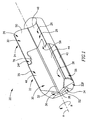
- FIG. 1 A gun-drill 20 in accordance with a first embodiment of the present invention is shown in Fig. 1 .
- the gun-drill 20 has a direction of rotation R around a longitudinal axis of rotation A defining a front-to-back direction, and comprises a cutting-head 22 detachably secured to a shank 24 at a shank forward end 24 F .
- a single, straight flute 26 extends axially along the shank 24 and the cutting-head 22, and comprises leading and trailing faces 28, 30, disposed at a flute angle ⁇ to each other.
- the flute leading and trailing faces 28, 30 meet at a flute apex 32 adjacent the axis of rotation A.
- the gun-drill 20 further comprises a fluid conduit 34 extending axially therethrough, comprising a conduit inner wall 36 and a fluid discharge outlet 38 at a cutting-head forward end 22 F .
- a fluid conduit 34 extending axially therethrough, comprising a conduit inner wall 36 and a fluid discharge outlet 38 at a cutting-head forward end 22 F .
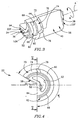
- the cutting-head 22 comprises a cutting portion 56 adjacent the cutting-head forward end 22 F and a cutting-head coupling portion 58 adjacent a cutting-head rear end 22 R thereof.
- the cutting portion 56 may comprise cutting geometries of any appropriate design.
- the cutting-head coupling portion 58 has a rearwardly facing cutting-head intermediate surface 60 which extends circumferentially from the cutting-head leading face 44 to the cutting-head trailing face 46 and radially inwardly from the cutting-head peripheral surface 40 to a cutting-head coupling wall 62.
- the cutting-head coupling wall 62 extends continuously circumferentially from the cutting-head leading face 44 to the cutting-head trailing face 46 and rearwardly away from the cutting-head intermediate surface 60 towards a rearwardly facing cutting-head support surface 64.
- the cutting-head conduit inner wall 52 meets the cutting-head support surface 64 at a cutting-head conduit aperture 52 A .
- the cutting-head coupling wall 62 comprises a rearwardly disposed cutting-head cylindrical surface 66 adjacent the cutting-head support surface 64, and a forwardly disposed generally frustoconical cutting-head fixation surface 68 extending axially forwardly while tapering radially inwardly from the cutting-head cylindrical surface 66 towards the cutting-head intermediate surface 60.
- the cutting-head coupling wall 62 extends continuously circumferentially along a cutting-head peripheral coupling angle ⁇ C which is greater than 180°.
- the cutting-head peripheral coupling angle ⁇ C is between 210° and 270°, and more commonly between 220° and 260°.
- the cutting-head peripheral coupling angle ⁇ C is approximately 235°.
- the cutting-head coupling portion 58 further comprises a cutting-head stop member 70 in a form of a recess in a rear portion of the cutting-head peripheral surface 40.
- the cutting-head stop member 70 is bounded by three surfaces: a generally radially outwardly facing cutting-head cylindrical wall 72, a generally axially rearwardly facing cutting-head top face 74, and a flat cutting-head stop wall 76 which faces generally tangentially away from the direction of rotation R while extending generally axially forwardly from the cutting-head intermediate surface 60 to the cutting-head top face 74 and generally radially outwardly from the cutting-head cylindrical wall 72 to the cutting-head peripheral surface 40.
- the cutting-head stop member 70 opens tangentially to the cutting-head trailing face 46, axially rearwardly to the cutting-head intermediate surface 60, and radially outwardly to the cutting-head peripheral surface 40.
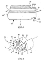
- a shank coupling portion 78 is located at the shank forward end 24 F and comprises a shank coupling wall 80 which extends continuously circumferentially from a shank leading face 48 to a shank trailing face 50 of the flute 26 and rearwardly towards a forwardly facing shank support surface 82.
- the shank conduit inner wall 54 meets the shank support surface 82 at a shank conduit aperture 54 A .
- the shank coupling wall 80 comprises a rearwardly disposed shank cylindrical surface 84 extending in a direction away from the shank support surface 82, and a forwardly disposed generally frustoconical shank fixation surface 86 extending axially forwardly while tapering radially inwardly from the shank cylindrical surface 84 towards a forwardly facing shank intermediate surface 88.
- a shank stop member 90 extends away from the shank intermediate surface 88, and comprises a generally radially inwardly facing shank cylindrical wall 92 which extends from the shank fixation surface 86 to a forwardly facing shank top face 94.
- a flat shank stop wall 96 facing generally tangentially in the direction of rotation R extends generally axially forwardly from the shank intermediate surface 86 to the shank top face 94 and generally radially outwardly from the shank cylindrical wall 92 to the shank peripheral surface 42.
- the shank intermediate surface 88 extends radially outwardly away from the shank fixation surface 86 to the shank peripheral surface 42 and continuously angularly from the shank leading face 48 of the flute 26 to the shank stop wall 96, while the shank stop member 90 extends angularly from the shank stop wall 96 to the shank trailing face 48 of the flute 26.
- both the shank peripheral surface 42 and the shank coupling wall 80 extend continuously angularly over a shank peripheral angle ⁇ S which is substantially equal to the cutting-head peripheral coupling angle ⁇ C .
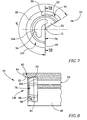
- Figs. 9 to 11 Securing the cutting-head 22 to the shank 24 is accomplished by positioning the cutting-head 22 with the cutting-head leading face 44 facing the shank trailing face 50 and the cutting-head coupling portion 58 adjacent the shank coupling portion 78, and sliding the cutting-head coupling portion 58 into the shank coupling portion 78 until the cutting-head fixation surface 68 abuts the shank fixation surface 86, to a released position of the cutting-head 22.
- Rotation of the cutting-head 22 relative to the shank 24 against the direction of rotation R of the gun-drill 20 positions the cutting-head 22 in the secured position shown in Figs.
- the cutting-head 22 is rotated relative to the shank 24 in the direction of rotation R to the released position. From the released position, the cutting-head 22 can be removed from the shank 24, and a new cutting-head 22 can then secured to the shank 24.
- the shank fixation surface 86 urges the cutting-head fixation surface 68 axially rearwardly, so that the cutting-head support surface 64 abuts the shank support surface 82, to positively and accurately position the cutting-head 22 in the shank 24.
- the shank conduit aperture 54 A and the cutting-head conduit aperture 52 A overlap, so that the cutting-head and shank conduit inner walls 52, 54 mate and co-align, thereby facilitating coolant flow through the shank 24 and the cutting-head 22 to the fluid discharge outlet 38.
- the cutting-head fixation surface 68 and the shank fixation surface 86 interlock co-axially, to provide self-clamping and self-centering of the cutting-head 22 in the shank 24. Because both the cutting-head coupling portion 58 and the shank coupling portion 78 extend continuously circumferentially through the peripheral angles ⁇ C , ⁇ S , respectively, which are greater than 180°, the shank fixation surface 86 urges the coupling-head 22 to axially align with the shank 24. Positive rotational location and alignment of the cutting-head 22 and the shank 24 are achieved by the cutting-head stop wall 76 abutting the shank stop wall 96, facilitating torque transmission from the shank 24 to the cutting-head 22.
- a first gap 98 extends circumferentially between the cutting-head cylindrical surface 66 and the shank cylindrical surface 84, a second gap 100 exists between the cutting-head intermediate surface 60 and the shank intermediate surface 88, a third gap 102 exists between the cutting-head cylindrical wall 72 and the shank cylindrical wall 92, and a fourth gap 104 exists between the cutting-head top face 74 and the shank top face 94.
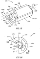
- FIG. 14 showing a gun-drill 220 in accordance with a second embodiment of the present invention. Since the gun-drill 220 in accordance with the second embodiment has many features which are similar to those of the gun-drill 20 in accordance with the first embodiment, the similar features of the gun-drill 220 in accordance with the second embodiment will be referred to herein below by reference numerals which are shifted by 200 from those of the gun-drill 20 in accordance with the first embodiment.
- the gun-drill 220 in accordance with the second embodiment has an axis of rotation A and a direction of rotation R defined much in the same manner as the axis of rotation A and a direction of rotation R of the gun-drill 20 in accordance with one embodiment.
- the gun-drill 220 has a cutting-head 222 detachably secured to a shank 224 at a shank forward end 224 F .
- Both the shank 224 and the cutting-head 222 have a a single, straight flute 226 extending axially along the shank 224 and the cutting-head 222.
- the flute has leading and trailing faces 228, 230 meeting at a flute apex 232 adjacent the axis of rotation A.
- a fluid conduit 234 having a conduit inner wall 236 and a fluid discharge outlet 238 formed at a cutting-head forward end 222 F extends axially through the gun-drill 220.
- the cutting-head 222 comprises a cutting portion 256 adjacent the cutting-head forward end 222 F and a cutting-head coupling portion 258 adjacent a cutting-head rear end 222 R thereof.
- a rearwardly facing cutting-head support surface 264 extends circumferentially from the cutting-head leading face 244 to the cutting-head trailing face 246 and radially inwardly from the cutting-head peripheral surface 240 to a cutting-head coupling wall 262.
- the cutting-head conduit inner wall 252 meets the cutting-head support surface 264 at a cutting-head conduit aperture 252 A .
- the cutting-head coupling wall 262 extends continuously circumferentially from the cutting-head leading face 244 to the cutting-head trailing face 246 and rearwardly away from the cutting-head support surface 264 towards a rearwardly facing cutting-head rear surface 306.
- the cutting-head coupling wall 262 comprises a rearwardly disposed cutting-head cylindrical surface 266 adjacent the cutting-head rear surface 306 and a forwardly disposed generally frustoconical cutting-head fixation surface 268 extending axially forwardly while tapering inwardly from the cutting-head cylindrical surface 266 towards the cutting-head support surface 264.
- the cutting-head coupling portion 258 further comprises a cutting-head stop member 270 in a form of a recess in a rear portion of the cutting-head peripheral surface 40.
- the cutting-head stop member 270 is bounded by three surfaces: a generally radially outwardly facing cutting-head cylindrical wall 272, a generally axially rearwardly facing cutting-head top face 274, and a flat cutting-head stop wall 276 facing generally tangentially away from the direction of rotation R and extending generally axially forwardly from the cutting-head support surface 264 to the cutting-head top face 274 and generally radially outwardly from the cutting-head cylindrical wall 272 to the cutting-head peripheral surface 240.
- the cutting-head stop member 270 opens tangentially to the cutting-head trailing face 246, axially rearwardly to the cutting-head support surface 264 and radially outwardly to the cutting-head peripheral surface 240.
- a shank coupling portion 278 is formed at the shank forward end 224 F and has a shank coupling wall 280 which extends continuously circumferentially from a shank leading face 248 to a shank trailing face 250 of the flute 226 and rearwardly from a forwardly facing shank support surface 282 towards a forwardly facing shank rear surface 308.
- the shank conduit inner wall 254 meets the shank support surface 282 at a shank conduit aperture 254 A .
- the shank coupling wall 280 has a shank cylindrical surface 284 extending in a direction away from the shank rear surface 308, and a shank fixation surface 286 extending from the shank cylindrical surface 284 forwardly towards the shank support surface 282.
- a shank stop member 290 extends away from the shank support surface 282 and has a generally radially inwardly facing shank cylindrical wall 292 which extends from the shank fixation surface 286 to a forwardly facing shank top face 294.
- a flat shank stop wall 296 faces generally tangentially in the direction of rotation R extends generally axially forwardly from the shank support surface 282 to the shank top face 294 and generally radially outwardly from the shank cylindrical wall 292 to the shank peripheral surface 242.
- Figs. 21 and 22 Attention is now drawn to Figs. 21 and 22 .
- the shank fixation surface 286 urges the cutting-head fixation surface 268 axially rearwardly, so that the cutting-head support surface 264 abuts the shank support surface 282, to positively and accurately position the cutting-head 222 in the shank 224.
- the shank conduit aperture 254 A and the cutting-head conduit aperture 252 A overlap, so that the cutting-head and shank conduit inner walls 252, 254 mate and co-align, thereby facilitating coolant flow through the shank 224 and the cutting-head 222 to the fluid discharge outlet 238.
- a first gap 298 extends circumferentially between the cutting-head cylindrical surface 266 and the shank cylindrical surface 284, a rear gap 310 exists between the cutting-head rear surface 306 and the shank rear surface 308, a third gap 302 exists between the cutting-head cylindrical wall 272 and the shank cylindrical wall 292, and a fourth gap 304 exists between the cutting-head top face 274 and the shank top face 294.
Landscapes
- Engineering & Computer Science (AREA)
- Mechanical Engineering (AREA)
- Drilling Tools (AREA)
- Earth Drilling (AREA)
- Processing Of Stones Or Stones Resemblance Materials (AREA)
Claims (27)
- Tiefbohrer (20, 220) mit einer Rotationslängsachse A, die eine Vorn-hinten-Richtung definiert, und einer Rotationsrichtung R und mit einem Schneidkopf (22, 222), der an einem Schaft (24, 224) lösbar befestigt ist; wobei
der Schneidkopf (22, 222) einen Schneidabschnitt (56, 256) angrenzend an ein vorderes Schneidkopfende (22F, 222F), und einen Schneidkopfkupplungsabschnitt (58, 258) angrenzend an ein hinteres Schneidkopfende (22R, 222R) aufweist, wobei der Schneidkopfkupplungsabschnitt (58, 258) eine axial nach hinten gewandte Schneidkopfauflagefläche (64, 264) und eine im allgemeinen kegelstumpfförmige Schneidkopffixierungsfläche (68, 268) aufweist, die sich radial nach innen verjüngt, während sie sich in Richtung des Schneidkopf-Schneidabschnitts (56, 256) nach vorn erstreckt;
der Schaft (24, 224) einen Schaftkupplungsabschnitt (78, 278) aufweist, der an einem vorderen Schaftende (24R, 224R) ausgebildet ist, wobei der Schaftkupplungsabschnitt (78, 278) eine axial nach vorn gewandte Schaftauflagefläche (82, 282) und eine im allgemeinen kegelstumpfförmige Schaftfixierungsfläche (86, 286) aufweist, die sich radial nach innen verjüngt und sich dabei in Richtung des vorderen Schaftendes (24R, 224R) nach vorn erstreckt; wobei
die Schaftfixierungsfläche (86, 286) sich entlang des Umfangs durchgehend von einer ersten Schaftnutseitenfläche (48, 248) zu einer zweiten Schaftnutseitenfläche (50, 250) über einen Schaftumfangswinkel ϕS größer als 180° erstreckt;
in einer befestigten Stellung der Schneidkopfkupplungsabschnitt (58, 258) und der Schaftkupplungsabschnitt (78, 278) koaxial ineinander eingreifen, wobei die Schneidkopfauflagefläche (64, 264) an der Schaftauflagefläche (82, 282) anliegt; und
eine Schneidkopf- und eine Schaftumfangsfläche (40, 42, 240, 242) und erste und zweite Schneidkopf- und Schaftnutseitenflächen (44, 48, 46, 50, 244, 248, 246, 250) in Eingriff stehen und miteinander ausgerichtet sind, dadurch gekennzeichnet, daß die Schneidkopffixierungsfläche (68, 268) sich entlang des Umfangs durchgehend von einer ersten Schneidkopfnutseitenfläche (46, 246) zu einer zweiten Schneidkopfnutseitenfläche (48, 248) über einen Schneidkopfumfangswinkel ϕC größer als 180° erstreckt. - Tiefbohrer (20, 220) nach Anspruch 1, wobei eine Fluidleitung (34, 234) sich axial durch den Schaft (24, 224) und den Schneidkopf (22, 222) erstreckt, wobei die Fluidleitung (34, 234) Schneidkopf- und Schaftleitungsinnenwände (52, 54, 252, 254) aufweist, die passend und ausgerichtet sind, wenn der Schneidkopf (22, 222) in der befestigten Stellung im Schaft (24, 224) ist.
- Tiefbohrer (20, 220) nach Anspruch 2, wobei die Schneidkopf- und Schaftleitungsinnenwände (52, 54, 252, 254) jeweils auf die aneinander anliegenden Schneidkopf- und Schaftauflageflächen (64, 264, 82, 282) an einer Schneidkopf- bzw. Schaftleitungsöffnung (52, 54, 252, 254) treffen und wobei in der befestigten Stellung die Schneidkopf- und die Schaftleitungsöffnung (52, 54, 252, 254) einander überlappen.
- Tiefbohrer (20, 220) nach Anspruch 1, wobei der Schneidkopfumfangswinkel ϕC im wesentlichen gleich dem Schaftumfangswinkel ϕS ist.
- Tiefbohrer (20, 220) nach Anspruch 4, wobei der Schneidkopfumfangswinkel ϕC und der Schaftumfangswinkel ϕS kleiner als 270° sind.
- Tiefbohrer (20, 220) nach Anspruch 4, wobei der Schneidkopfumfangswinkel ϕC und der Schaftumfangswinkel ϕS zwischen 220° und 250° sind.
- Tiefbohrer (20) nach Anspruch 4, wobei der Schneidkopfumfangswinkel ϕC und der Schaftumfangswinkel ϕS 235° sind.
- Tiefbohrer (20, 220) nach Anspruch 1, wobei die Schneidkopf- und die Schaftauflagefläche (64, 82, 264, 282) eben sind.
- Tiefbohrer (20, 220) nach Anspruch 8, wobei die Schneidkopf- und die Schaftauflagefläche (64, 82, 264, 282) senkrecht zur Rotationsachse A sind.
- Tiefbohrer (20, 220) nach Anspruch 1, wobei der Schneidkopfkupplungsabschnitt (58) eine zylindrische Schneidkopffläche (66, 266) aufweist, die sich axial weg von der Schneidkopffixierungsfläche (68, 268) und entlang des Umfangs durchgehend von der ersten Schneidkopffläche (44, 244) zur zweiten Schneidkopffläche (46, 246) erstreckt, und
der Schaftkupplungsabschnitt (78, 278) eine zylindrische Schaftfläche (84, 284) aufweist, die sich axial weg von der Schaftfixierungsfläche (86, 286) und entlang des Umfangs durchgehend von der ersten Schaft-Seitenfläche (48, 248) zur zweiten Schaft-Seitenfläche (50, 250) erstreckt. - Tiefbohrer (20) nach Anspruch 10, wobei in der befestigten Stellung ein erster Spalt (98, 298) sich durchgehend entlang des Umfangs zwischen der zylindrischen Schneidkopffläche (66, 266) und der zylindrischen Schaftfläche (84, 284) erstreckt.
- Tiefbohrer (20, 220) nach Anspruch 1, wobei
der Schneidkopfkupplungsabschnitt (58, 258) ein Schneidkopfanschlagteil (70, 270) mit einer Schneidkopfanschlagwand (76, 276) aufweist, die von der Rotationsrichtung A abgewandt ist und sich im allgemeinen axial nach vorn weg von der Schneidkopfkupplungswand (62, 262) (40, 240) erstreckt; und
der Schaftkupplungsabschnitt (78, 278) ein Schaftanschlagteil (90) mit einer Schaftanschlagwand (96) aufweist, die der Rotationsrichtung A zugewandt ist und sich im allgemeinen axial nach vorn weg von der Schaftkupplungswand (80, 280) erstreckt. - Tiefbohrer (20, 220) nach Anspruch 12, wobei in der befestigten Stellung die Schneidkopfanschlagwand (76, 276) und die Schaftanschlagwand (96, 296) aneinander anliegen.
- Tiefbohrer (20, 220) nach Anspruch 12, wobei
das Schneidkopfanschlagteil (70, 270) eine im allgemeinen radial nach außen gewandte zylindrische Schneidkopfwand (72, 272) und eine axial nach hinten gewandte Schneidkopfstirnseitenfläche (74, 274) aufweist und
das Schaftanschlagteil (90, 290) eine im allgemeinen radial nach innen gewandte zylindrische Schaftwand (92, 292) und eine axial nach vorn gewandte Schaftstirnseitenfläche (94, 294) aufweist. - Tiefbohrer (20, 220) nach Anspruch 14, wobei in der befestigten Stellung eine dritter Spalt (102, 302) zwischen der zylindrischen Schneidkopfwand (72, 272) und der zylindrischen Schaftwand (92, 292) besteht.
- Tiefbohrer (20, 220) nach Anspruch 14, wobei in der befestigten Stellung ein vierter Spalt (104, 304) zwischen der Schneidkopfstirnseitenfläche (74, 274) und der Schaftstirnseitenfläche (94, 294) besteht.
- Tiefbohrer (20) nach Anspruch 1, wobei
eine axial nach hinten gewandte Schneidkopfzwischenfläche (60) sich zwischen der Schneidkopffixierungsfläche (68) und der Schneidkopfumfangsfläche (40) befindet und
eine axial nach vorn gewandte Schaftzwischenfläche (88) sich zwischen der Schaftfixierungsfläche (86) und der Schaftumfangsfläche (42) befindet. - Tiefbohrer (20) nach Anspruch 17, wobei ein zweiter Spalt (100) zwischen der Schneidkopfzwischenfläche und der Schaftzwischenfläche besteht.
- Tiefbohrer (220) nach Anspruch 1, wobei in der befestigten Stellung ein hinterer Spalt (310) zwischen einer im allgemeinen axial nach hinten gewandten Schneidkopfrückseitenfläche (306), die benachbart zur zylindrischen Schneidkopffläche (266) angeordnet ist, und einer im allgemeinen axial nach vorn gewandten Schaftrückseitenfläche (288), die benachbart zur zylindrischen Schaftfläche (308) angeordnet ist.
- Auswechselbarer Schneidkopf (22, 222), der zum Montieren an einem Schaft (24, 224) eines Tiefbohrers (20, 220) mit einer Rotationsachse R bestimmt ist und der aufweist: eine Schneidkopfumfangsfläche (40, 240), einen Schneidkopfschneidabschnitt (56, 256), benachbart zu einem vorderen Schneidkopfende (22F, 222F), einen Schneidkopf kupplungsabschnitt (58), benachbart zu einem hinteren Schneidkopfende (22R, 222R), und eine sich axial erstreckende Nut (26, 226) mit einer ersten und zweiten Schneidkopf-Seitenfläche (44, 46, 244, 246), die sich im allgemeinen radial zur Schneidkopfumfangsfläche (40, 240) erstrecken;
wobei der Schneidkopfkupplungsabschnitt (58, 258) eine axial nach hinten gewandte Schneidkopfauflagefläche (64, 264) und eine Schneidkopfkupplungswand (62, 262) aufweist;
wobei die Schneidkopfkupplungswand (62, 262) eine hinten befindliche zylindrische Schneidkopffläche (66, 266) aufweist, die sich nach vorn zu einer sich nach vorn verjüngenden Schneidkopffixierungsfläche (68, 268), benachbart zum Schneidkopfschneidabschnitt (56, 256), erstreckt, dadurch gekennzeichnet, daß die Schneidkopfkupplungswand (62, 262) sich axial nach hinten weg vom Schneidabschnitt (56, 256) und entlang des Umfangs durchgehend von der ersten Schneidkopf-Seitenfläche (46, 246) zur zweiten Schneidkopf-Seitenfläche (48, 248) über einen Umfangsschneidkopfwinkel ϕC von mehr als 180° erstreckt. - Schneidkopf (.22, 222) nach Anspruch 20, wobei ein Schneidkopfanschlagteil (70, 270) sich axial nach vorn weg von der Schneidkopfkupplungswand (62, 262) zum Schneidkopfschneidabschnitt (56), benachbart zur zweiten Schneidkopf-Seitenfläche (46), erstreckt.
- Schneidkopf (22, 222) nach Anspruch 21, wobei das Schneidkopfanschlagteil (70, 270) sich tangential nach vorn zur zweiten Schneidkopf-Seitenfläche (48, 248) öffnet.
- Schneidkopf (22, 222) nach Anspruch 21, wobei das Schneidkopfanschlagteil (70, 270) sich radial nach außen zur Schneidkopfumfangsfläche (40, 240) öffnet.
- Schneidkopf (22, 222) nach Anspruch 21, wobei das Schneidkopfanschlagteil (70, 270) eine im allgemeinen axial nach hinten gewandte Schneidkopfstirnseitenfläche (74, 274), eine im allgemeinen radial nach außen gewandte zylindrische Schneidkopfwand (72, 272) und eine Schneidkopfanschlagwand (76, 276) aufweist, die sich weg vom Schneidkopfkupplungsabschnitt (58, 258) zur Schneidkopfstirnseitenfläche (74, 274) und weg von der zylindrischen Schneidkopfwand (72, 272) zur Schneidkopfumfangsfläche (40, 240) erstreckt.
- Schneidkopf (20) nach Anspruch 21, wobei eine axial nach hinten gewandte Schneidkopfzwischenfläche (60) sich zwischen der Schneidkopffixierungsfläche (68) und der Schneidkopfumfangsfläche (40) befindet und die Schneidkopfauflagefläche (64) sich am hinteren Schneidkopfende (22R), benachbart zur zylindrischen Schneidkopffläche (66), befindet.
- Schneidkopf (222) nach Anspruch 21, wobei die Schneidkopfauflagefläche (264) sich zwischen der Schneidkopffixierungsfläche (268) und der Schneidkopfumfangsfläche (240) befindet und eine im allgemeinen axial nach hinten gewandte hintere Schneidkopffläche (306) sich am hinteren Schneidkopfende (222R), benachbart zur zylindrischen Schneidkopffläche (266), befindet.
- Verfahren zum Montieren eines Tiefbohrers (20, 220) mit einem Schneidkopf (22, 222) und einem Schaft (24, 224), wobei der Tiefbohrer (20, 220) eine Rotationslängsachse A, die sich mittig entlang desselben erstreckt und eine Vorn-hinten-Richtung definiert, und eine Rotationsrichtung R hat und eine Schneidkopf- und eine Schaftumfangsfläche (40, 42, 240, 242) und erste und zweite Schneidkopf- und Schaftnutseitenflächen (44, 48, 46, 50, 244, 248, 246, 250) aufweist;
der Schaft (24, 224) einen Schaftkupplungsabschnitt (78, 278), der an einem vorderen Schaftende (24F, 224F) ausgebildet ist, und eine sich nach vorn verjüngende Schaftfixierungsfläche (86) und eine zylindrische Schaftfläche (84), die sich von diesen nach hinten erstreckt, und eine axial nach vorn gewandte Schaftauflagefläche (82) aufweist, wobei die Schaftfixierungsfläche (86, 286) und die zylindrische Schaftfläche (84, 284) sich entlang des Umfangs durchgehend.von einer ersten Schaft-Seitenfläche (48, 248) zu einer zweiten Schaft-Seitenfläche (50, 250) entlang eines Winkels ϕS größer als 180° erstrecken;
der Schneidkopf (22, 222) einen Schneidabschnitt (56, 256), benachbart zu einem vorderen Schneidkopfende (22F, 222F), und einen Schneidkopfkupplungsabschnitt (58, 258), benachbart zu einem hinteren Schneidkopfende (22R, 222R), hat, wobei der Schneidkopfkupplungsabschnitt (58, 258) eine sich nach vorn verjüngende Schneidkopffixierungsfläche (68, 268), eine zylindrische Schneidkopffläche (66, 266), die sich von dieser nach hinten erstreckt, und eine nach hinten gewandte Schrieidkopfauflagefläche (64, 264) aufweist, wobei die Schneidkopffixierungsfläche (68, 268) und die zylindrische Schneidkopffläche (66, 266) sich entlang des Umfangs durchgehend von einer ersten Schneidkopf-Seitenfläche (46, 246) zu einer zweiten Schneidkopf-Seitenfläche (48, 248) entlang eines Winkels ϕC größer als 180° erstrecken;
wobei das Verfahren die Schritte aufweist:Positionieren des Schneidkopfs (22, 222) und des Schafts (24, 224), so daß die erste Schneidkopf-Seitenfläche (46, 246) der zweiten Schaft-Seitenfläche (50, 250) zugewandt ist;gleitfähiges Einfügen des Schneidkopfkupplungsabschnitts (58, 258) in den Schaftkupplungsabschnitt (78, 278), bis ein Kontakt zwischen der Schneidkopffixierungsfläche (68, 268) und der Schaftfixierungsfläche (86, 286) hergestellt ist; undDrehen des Schneidkopfs (22) relativ zum Schaft (24) in einer Richtung entgegen der Rotationsrichtung R, bis die Schneidkopffixierungsfläche (68) an der Schaftfixierungsfläche (86) anliegt und die Schneidkopf- und die Schaftumfangsfläche (40, 42, 240, 242) und die ersten und zweiten Schneidkopf- und Schaftnutseitenflächen (44, 48, 46, 50, 244, 248, 246, 250) sich miteinander ausrichten.
Priority Applications (2)
| Application Number | Priority Date | Filing Date | Title |
|---|---|---|---|
| PL05763097T PL1781439T3 (pl) | 2004-08-23 | 2005-07-26 | Wiertło działowe |
| SI200530366T SI1781439T1 (sl) | 2004-08-23 | 2005-07-26 | Sveder za globinsko vrtanje |
Applications Claiming Priority (2)
| Application Number | Priority Date | Filing Date | Title |
|---|---|---|---|
| IL163679A IL163679A (en) | 2004-08-23 | 2004-08-23 | Buy a drill |
| PCT/IL2005/000799 WO2006021947A1 (en) | 2004-08-23 | 2005-07-26 | Gun-drill |
Publications (2)
| Publication Number | Publication Date |
|---|---|
| EP1781439A1 EP1781439A1 (de) | 2007-05-09 |
| EP1781439B1 true EP1781439B1 (de) | 2008-06-04 |
Family
ID=35219546
Family Applications (1)
| Application Number | Title | Priority Date | Filing Date |
|---|---|---|---|
| EP05763097A Active EP1781439B1 (de) | 2004-08-23 | 2005-07-26 | Tiefbohrer |
Country Status (24)
| Country | Link |
|---|---|
| US (1) | US7393162B2 (de) |
| EP (1) | EP1781439B1 (de) |
| JP (1) | JP4825208B2 (de) |
| KR (1) | KR100982838B1 (de) |
| CN (1) | CN100503105C (de) |
| AT (1) | ATE397507T1 (de) |
| AU (1) | AU2005276110A1 (de) |
| BG (1) | BG65956B1 (de) |
| BR (1) | BRPI0514427B1 (de) |
| CA (1) | CA2579419C (de) |
| DE (1) | DE602005007359D1 (de) |
| DK (1) | DK1781439T3 (de) |
| ES (1) | ES2307191T3 (de) |
| IL (1) | IL163679A (de) |
| MX (1) | MX2007001989A (de) |
| NO (1) | NO20071497L (de) |
| NZ (1) | NZ552992A (de) |
| PL (1) | PL1781439T3 (de) |
| PT (1) | PT1781439E (de) |
| RU (1) | RU2372170C2 (de) |
| SI (1) | SI1781439T1 (de) |
| TW (1) | TW200704463A (de) |
| WO (1) | WO2006021947A1 (de) |
| ZA (1) | ZA200702062B (de) |
Cited By (1)
| Publication number | Priority date | Publication date | Assignee | Title |
|---|---|---|---|---|
| USD1009108S1 (en) | 2020-09-21 | 2023-12-26 | Kyocera Unimerco Tooling A/S | Drill |
Families Citing this family (21)
| Publication number | Priority date | Publication date | Assignee | Title |
|---|---|---|---|---|
| IL181295A (en) | 2007-02-12 | 2011-07-31 | Iscar Ltd | A cutting tool that includes a self-locking release bar head |
| DE102007044095A1 (de) * | 2007-09-14 | 2009-03-19 | Hartmetall-Werkzeugfabrik Paul Horn Gmbh | Bohrwerkzeug mit Bohrkrone |
| KR101125677B1 (ko) | 2009-05-25 | 2012-03-27 | 동양대학교 산학협력단 | 홍삼 및 오미자를 주성분으로 하는 건강기능식품용 진액 조성물, 건강기능식품 및 이의 제조방법 |
| DE102009042665A1 (de) * | 2009-09-23 | 2011-05-19 | Esa Eppinger Gmbh | Schnittstelle zwischen einem Aufnahmekörper und einem insbesondere als Werkzeug- oder Werkstückhalter ausgebildeten Einsatz |
| CN102159351B (zh) * | 2009-12-08 | 2014-12-17 | Osg株式会社 | 不重磨式旋转工具 |
| IL203798A (en) * | 2010-02-08 | 2013-03-24 | Iscar Ltd | Clamping mechanism |
| IL206283A0 (en) * | 2010-06-10 | 2010-11-30 | Iscar Ltd | Cutting tool and nozzle therefor |
| US8869877B2 (en) | 2010-10-11 | 2014-10-28 | Hamilton Sundstrand Space Systems International, Inc. | Monolithic cold plate configuration |
| DE102010050351A1 (de) | 2010-11-05 | 2012-05-10 | Botek Präzisionsbohrtechnik Gmbh | Einlippenbohrer |
| EP2745966A1 (de) * | 2012-12-21 | 2014-06-25 | HILTI Aktiengesellschaft | Bohrkrone mit einem austauschbaren Schneidabschnitt |
| TWI476057B (zh) * | 2012-12-21 | 2015-03-11 | Metal Ind Res & Dev Ct | 替換式深孔鑽 |
| EP2952278B1 (de) * | 2013-01-29 | 2020-03-11 | OSG Corporation | Bohrer |
| KR101740847B1 (ko) * | 2013-03-26 | 2017-05-26 | 오에스지 가부시키가이샤 | 절삭액 공급 구멍이 형성된 3 장 날 드릴 |
| US10792738B2 (en) * | 2016-07-26 | 2020-10-06 | Kyocera Corporation | Cutting tool and method of manufacturing machined product |
| DE102018001056A1 (de) | 2018-02-07 | 2019-08-08 | Institut für innovative Technologien, Technologietransfer, Ausbildung und berufsbegleitende Weiterbildung (ITW) e. V. | Einlippenbohrer mit Wechselkopf für das Tiefbohren |
| KR200490029Y1 (ko) | 2019-03-19 | 2019-09-10 | 이재화 | 정사각형 인서트를 이용한 건드릴 |
| KR200490223Y1 (ko) | 2019-03-19 | 2019-10-14 | 이재화 | 트위스트 건드릴 |
| KR20210026969A (ko) | 2019-09-02 | 2021-03-10 | 이재화 | 정사각형 인서트를 이용한 건드릴 |
| KR102223956B1 (ko) | 2019-10-01 | 2021-03-04 | 이재화 | 트위스트 건드릴 |
| KR102134131B1 (ko) | 2020-02-12 | 2020-07-15 | 이재관 | 팔각형 형상의 인서트를 이용한 건드릴 |
| US11524344B2 (en) | 2020-04-22 | 2022-12-13 | Iscar, Ltd. | Rotationally asymmetric cutting insert having a single radially extending cutting-edge portion and rotary cutting tool |
Family Cites Families (16)
| Publication number | Priority date | Publication date | Assignee | Title |
|---|---|---|---|---|
| US2346546A (en) | 1942-01-23 | 1944-04-11 | Niles Bement Pond Co | Deep hole drill |
| US3153356A (en) | 1962-12-17 | 1964-10-20 | Howard K Dearborn | Gun drill |
| USRE26452E (en) | 1964-10-20 | 1968-09-10 | Gun drill | |
| US3304816A (en) * | 1965-04-07 | 1967-02-21 | Louis C Galorneau | Detachable drill tip and coupling means |
| JPS4991889A (de) * | 1972-12-31 | 1974-09-02 | ||
| US4437802A (en) * | 1981-09-14 | 1984-03-20 | Hall Jr John J | Boring tool having a detachable cutting blade |
| SU1757785A1 (ru) * | 1991-01-22 | 1992-08-30 | Киевский Политехнический Институт Им.50-Летия Великой Октябрьской Социалистической Революции | Сверло |
| SE511429C2 (sv) * | 1996-09-13 | 1999-09-27 | Seco Tools Ab | Verktyg, skärdel, verktygskropp för skärande bearbetning samt metod för montering av skärdel till verktygskropp |
| IL120948A0 (en) * | 1997-05-29 | 1997-09-30 | Iscar Ltd | Cutting tool assembly |
| IL125766A (en) * | 1998-08-13 | 2002-12-01 | Iscar Ltd | The barrel of a tool and a rotating cutting head for placing on it in the form of a self-lining |
| WO2002005990A1 (fr) | 2000-07-14 | 2002-01-24 | Sumitomo Electric Industries, Ltd. | Outil de decoupe jetable |
| US6506003B1 (en) * | 2001-10-02 | 2003-01-14 | Kennametal Inc. | Cutting tool |
| US6582164B1 (en) * | 2002-02-25 | 2003-06-24 | Kennametal Inc. | Roller twist drill |
| US7004691B2 (en) * | 2002-11-15 | 2006-02-28 | Unitac Incorporated | Deep hole cutter |
| US7309196B2 (en) * | 2004-10-05 | 2007-12-18 | Kennametal Inc. | Modular drill |
| IL164888A (en) * | 2004-10-28 | 2009-07-20 | Iscar Ltd | Cutting tool and cutting head for it |
-
2004
- 2004-08-23 IL IL163679A patent/IL163679A/en not_active IP Right Cessation
-
2005
- 2005-07-26 PT PT05763097T patent/PT1781439E/pt unknown
- 2005-07-26 SI SI200530366T patent/SI1781439T1/sl unknown
- 2005-07-26 DE DE602005007359T patent/DE602005007359D1/de active Active
- 2005-07-26 JP JP2007529130A patent/JP4825208B2/ja not_active Expired - Fee Related
- 2005-07-26 KR KR1020077004115A patent/KR100982838B1/ko active IP Right Grant
- 2005-07-26 CN CNB200580028614XA patent/CN100503105C/zh not_active Expired - Fee Related
- 2005-07-26 EP EP05763097A patent/EP1781439B1/de active Active
- 2005-07-26 ZA ZA200702062A patent/ZA200702062B/xx unknown
- 2005-07-26 NZ NZ552992A patent/NZ552992A/en not_active IP Right Cessation
- 2005-07-26 BR BRPI0514427-2A patent/BRPI0514427B1/pt not_active IP Right Cessation
- 2005-07-26 RU RU2007106223/02A patent/RU2372170C2/ru not_active IP Right Cessation
- 2005-07-26 PL PL05763097T patent/PL1781439T3/pl unknown
- 2005-07-26 ES ES05763097T patent/ES2307191T3/es active Active
- 2005-07-26 AU AU2005276110A patent/AU2005276110A1/en not_active Abandoned
- 2005-07-26 MX MX2007001989A patent/MX2007001989A/es active IP Right Grant
- 2005-07-26 CA CA2579419A patent/CA2579419C/en not_active Expired - Fee Related
- 2005-07-26 DK DK05763097T patent/DK1781439T3/da active
- 2005-07-26 WO PCT/IL2005/000799 patent/WO2006021947A1/en active IP Right Grant
- 2005-07-26 AT AT05763097T patent/ATE397507T1/de active
- 2005-07-29 TW TW094125798A patent/TW200704463A/zh unknown
- 2005-08-12 US US11/202,348 patent/US7393162B2/en active Active
-
2007
- 2007-02-21 BG BG109823A patent/BG65956B1/bg unknown
- 2007-03-21 NO NO20071497A patent/NO20071497L/no not_active Application Discontinuation
Cited By (1)
| Publication number | Priority date | Publication date | Assignee | Title |
|---|---|---|---|---|
| USD1009108S1 (en) | 2020-09-21 | 2023-12-26 | Kyocera Unimerco Tooling A/S | Drill |
Also Published As
| Publication number | Publication date |
|---|---|
| NO20071497L (no) | 2007-05-09 |
| BG65956B1 (bg) | 2010-07-30 |
| PL1781439T3 (pl) | 2008-12-31 |
| DE602005007359D1 (de) | 2008-07-17 |
| KR20070037644A (ko) | 2007-04-05 |
| EP1781439A1 (de) | 2007-05-09 |
| BRPI0514427B1 (pt) | 2017-11-28 |
| ATE397507T1 (de) | 2008-06-15 |
| AU2005276110A1 (en) | 2006-03-02 |
| US7393162B2 (en) | 2008-07-01 |
| US20060039766A1 (en) | 2006-02-23 |
| IL163679A (en) | 2009-02-11 |
| NZ552992A (en) | 2009-07-31 |
| ES2307191T3 (es) | 2008-11-16 |
| CN100503105C (zh) | 2009-06-24 |
| CA2579419C (en) | 2010-07-06 |
| PT1781439E (pt) | 2008-08-01 |
| CN101005913A (zh) | 2007-07-25 |
| JP4825208B2 (ja) | 2011-11-30 |
| BG109823A (bg) | 2007-12-28 |
| ZA200702062B (en) | 2009-02-25 |
| IL163679A0 (en) | 2005-12-18 |
| KR100982838B1 (ko) | 2010-09-16 |
| MX2007001989A (es) | 2007-04-23 |
| CA2579419A1 (en) | 2006-03-02 |
| WO2006021947A1 (en) | 2006-03-02 |
| JP2008510630A (ja) | 2008-04-10 |
| TW200704463A (en) | 2007-02-01 |
| RU2007106223A (ru) | 2008-09-27 |
| DK1781439T3 (da) | 2008-09-15 |
| RU2372170C2 (ru) | 2009-11-10 |
| BRPI0514427A (pt) | 2008-06-10 |
| SI1781439T1 (sl) | 2008-10-31 |
Similar Documents
| Publication | Publication Date | Title |
|---|---|---|
| EP1781439B1 (de) | Tiefbohrer | |
| EP1280624B1 (de) | Werkzeugkupplung | |
| EP2164666B1 (de) | Mehrteilige werkzeuganordnung und schneidwerkzeug | |
| US8668413B2 (en) | Coupler for a quick change insert rotary cutting tool | |
| KR102360620B1 (ko) | 탄성적으로 이동가능한 인접 부분들이 제공된 중앙 리세스를 가진 헤드 지지 표면을 포함하는 공구 섕크 | |
| AU2001244500A1 (en) | Tool joint | |
| KR20110005243A (ko) | 회전 절삭 기계가공용 공구 | |
| KR20110004851A (ko) | 공구, 공구 본체 및 절삭 헤드 | |
| EP1951461A1 (de) | Schneidwerkzeuganordnung | |
| WO2003047797A1 (fr) | Foret a pointe jetable | |
| EP3288703B1 (de) | Werkzeugkupplungsanordnung für bohrer und reibahlen | |
| US10576552B2 (en) | Rotary tool | |
| US6004083A (en) | System for mounting a chuck device to a rotary power tool | |
| JP2007167977A (ja) | 刃具交換式回転工具、その刃具交換式回転工具に用いられる交換刃具およびホルダー | |
| US20240139829A1 (en) | Replaceable cutting head, tool holder and morse taper rotary cutting tool having fastening member | |
| JP2004283970A (ja) | 深孔切削具 | |
| CN114193523A (zh) | 切削工具 |
Legal Events
| Date | Code | Title | Description |
|---|---|---|---|
| PUAI | Public reference made under article 153(3) epc to a published international application that has entered the european phase |
Free format text: ORIGINAL CODE: 0009012 |
|
| 17P | Request for examination filed |
Effective date: 20070223 |
|
| AK | Designated contracting states |
Kind code of ref document: A1 Designated state(s): AT BE BG CH CY CZ DE DK EE ES FI FR GB GR HU IE IS IT LI LT LU LV MC NL PL PT RO SE SI SK TR |
|
| GRAP | Despatch of communication of intention to grant a patent |
Free format text: ORIGINAL CODE: EPIDOSNIGR1 |
|
| DAX | Request for extension of the european patent (deleted) | ||
| GRAS | Grant fee paid |
Free format text: ORIGINAL CODE: EPIDOSNIGR3 |
|
| GRAA | (expected) grant |
Free format text: ORIGINAL CODE: 0009210 |
|
| AK | Designated contracting states |
Kind code of ref document: B1 Designated state(s): AT BE BG CH CY CZ DE DK EE ES FI FR GB GR HU IE IS IT LI LT LU LV MC NL PL PT RO SE SI SK TR |
|
| REG | Reference to a national code |
Ref country code: GB Ref legal event code: FG4D |
|
| REG | Reference to a national code |
Ref country code: CH Ref legal event code: EP |
|
| REF | Corresponds to: |
Ref document number: 602005007359 Country of ref document: DE Date of ref document: 20080717 Kind code of ref document: P |
|
| REG | Reference to a national code |
Ref country code: SE Ref legal event code: TRGR |
|
| REG | Reference to a national code |
Ref country code: PT Ref legal event code: SC4A Free format text: AVAILABILITY OF NATIONAL TRANSLATION Effective date: 20080723 |
|
| REG | Reference to a national code |
Ref country code: IE Ref legal event code: FG4D |
|
| REG | Reference to a national code |
Ref country code: DK Ref legal event code: T3 |
|
| REG | Reference to a national code |
Ref country code: CH Ref legal event code: NV Representative=s name: VOSSIUS & PARTNER |
|
| REG | Reference to a national code |
Ref country code: ES Ref legal event code: FG2A Ref document number: 2307191 Country of ref document: ES Kind code of ref document: T3 |
|
| PG25 | Lapsed in a contracting state [announced via postgrant information from national office to epo] |
Ref country code: LV Free format text: LAPSE BECAUSE OF FAILURE TO SUBMIT A TRANSLATION OF THE DESCRIPTION OR TO PAY THE FEE WITHIN THE PRESCRIBED TIME-LIMIT Effective date: 20080604 |
|
| REG | Reference to a national code |
Ref country code: HU Ref legal event code: AG4A Ref document number: E003821 Country of ref document: HU |
|
| REG | Reference to a national code |
Ref country code: PL Ref legal event code: T3 |
|
| PG25 | Lapsed in a contracting state [announced via postgrant information from national office to epo] |
Ref country code: IS Free format text: LAPSE BECAUSE OF FAILURE TO SUBMIT A TRANSLATION OF THE DESCRIPTION OR TO PAY THE FEE WITHIN THE PRESCRIBED TIME-LIMIT Effective date: 20081004 Ref country code: LT Free format text: LAPSE BECAUSE OF FAILURE TO SUBMIT A TRANSLATION OF THE DESCRIPTION OR TO PAY THE FEE WITHIN THE PRESCRIBED TIME-LIMIT Effective date: 20080604 |
|
| PG25 | Lapsed in a contracting state [announced via postgrant information from national office to epo] |
Ref country code: RO Free format text: LAPSE BECAUSE OF FAILURE TO SUBMIT A TRANSLATION OF THE DESCRIPTION OR TO PAY THE FEE WITHIN THE PRESCRIBED TIME-LIMIT Effective date: 20080604 Ref country code: SK Free format text: LAPSE BECAUSE OF FAILURE TO SUBMIT A TRANSLATION OF THE DESCRIPTION OR TO PAY THE FEE WITHIN THE PRESCRIBED TIME-LIMIT Effective date: 20080604 |
|
| PG25 | Lapsed in a contracting state [announced via postgrant information from national office to epo] |
Ref country code: MC Free format text: LAPSE BECAUSE OF NON-PAYMENT OF DUE FEES Effective date: 20080731 |
|
| PLBE | No opposition filed within time limit |
Free format text: ORIGINAL CODE: 0009261 |
|
| STAA | Information on the status of an ep patent application or granted ep patent |
Free format text: STATUS: NO OPPOSITION FILED WITHIN TIME LIMIT |
|
| PG25 | Lapsed in a contracting state [announced via postgrant information from national office to epo] |
Ref country code: EE Free format text: LAPSE BECAUSE OF FAILURE TO SUBMIT A TRANSLATION OF THE DESCRIPTION OR TO PAY THE FEE WITHIN THE PRESCRIBED TIME-LIMIT Effective date: 20080604 Ref country code: BG Free format text: LAPSE BECAUSE OF FAILURE TO SUBMIT A TRANSLATION OF THE DESCRIPTION OR TO PAY THE FEE WITHIN THE PRESCRIBED TIME-LIMIT Effective date: 20080904 |
|
| 26N | No opposition filed |
Effective date: 20090305 |
|
| PG25 | Lapsed in a contracting state [announced via postgrant information from national office to epo] |
Ref country code: IE Free format text: LAPSE BECAUSE OF NON-PAYMENT OF DUE FEES Effective date: 20080726 |
|
| PGFP | Annual fee paid to national office [announced via postgrant information from national office to epo] |
Ref country code: DK Payment date: 20090602 Year of fee payment: 5 |
|
| PGFP | Annual fee paid to national office [announced via postgrant information from national office to epo] |
Ref country code: FI Payment date: 20090601 Year of fee payment: 5 |
|
| PGFP | Annual fee paid to national office [announced via postgrant information from national office to epo] |
Ref country code: BE Payment date: 20090602 Year of fee payment: 5 |
|
| PGFP | Annual fee paid to national office [announced via postgrant information from national office to epo] |
Ref country code: CH Payment date: 20090602 Year of fee payment: 5 |
|
| PGFP | Annual fee paid to national office [announced via postgrant information from national office to epo] |
Ref country code: HU Payment date: 20090609 Year of fee payment: 5 Ref country code: NL Payment date: 20090531 Year of fee payment: 5 Ref country code: SI Payment date: 20090601 Year of fee payment: 5 |
|
| PG25 | Lapsed in a contracting state [announced via postgrant information from national office to epo] |
Ref country code: CY Free format text: LAPSE BECAUSE OF FAILURE TO SUBMIT A TRANSLATION OF THE DESCRIPTION OR TO PAY THE FEE WITHIN THE PRESCRIBED TIME-LIMIT Effective date: 20080604 Ref country code: LU Free format text: LAPSE BECAUSE OF NON-PAYMENT OF DUE FEES Effective date: 20080726 |
|
| PG25 | Lapsed in a contracting state [announced via postgrant information from national office to epo] |
Ref country code: GR Free format text: LAPSE BECAUSE OF FAILURE TO SUBMIT A TRANSLATION OF THE DESCRIPTION OR TO PAY THE FEE WITHIN THE PRESCRIBED TIME-LIMIT Effective date: 20080905 |
|
| BERE | Be: lapsed |
Owner name: ISCAR LTD. Effective date: 20100731 |
|
| REG | Reference to a national code |
Ref country code: NL Ref legal event code: V1 Effective date: 20110201 |
|
| REG | Reference to a national code |
Ref country code: CH Ref legal event code: PL |
|
| PG25 | Lapsed in a contracting state [announced via postgrant information from national office to epo] |
Ref country code: HU Free format text: LAPSE BECAUSE OF NON-PAYMENT OF DUE FEES Effective date: 20100727 Ref country code: CH Free format text: LAPSE BECAUSE OF NON-PAYMENT OF DUE FEES Effective date: 20100731 Ref country code: LI Free format text: LAPSE BECAUSE OF NON-PAYMENT OF DUE FEES Effective date: 20100731 |
|
| REG | Reference to a national code |
Ref country code: SI Ref legal event code: KO00 Effective date: 20110314 |
|
| PG25 | Lapsed in a contracting state [announced via postgrant information from national office to epo] |
Ref country code: SI Free format text: LAPSE BECAUSE OF NON-PAYMENT OF DUE FEES Effective date: 20100727 Ref country code: FI Free format text: LAPSE BECAUSE OF NON-PAYMENT OF DUE FEES Effective date: 20100726 Ref country code: NL Free format text: LAPSE BECAUSE OF NON-PAYMENT OF DUE FEES Effective date: 20110201 |
|
| PG25 | Lapsed in a contracting state [announced via postgrant information from national office to epo] |
Ref country code: BE Free format text: LAPSE BECAUSE OF NON-PAYMENT OF DUE FEES Effective date: 20100731 |
|
| REG | Reference to a national code |
Ref country code: DK Ref legal event code: EBP |
|
| PG25 | Lapsed in a contracting state [announced via postgrant information from national office to epo] |
Ref country code: DK Free format text: LAPSE BECAUSE OF NON-PAYMENT OF DUE FEES Effective date: 20100802 |
|
| REG | Reference to a national code |
Ref country code: FR Ref legal event code: PLFP Year of fee payment: 12 |
|
| REG | Reference to a national code |
Ref country code: FR Ref legal event code: PLFP Year of fee payment: 13 |
|
| REG | Reference to a national code |
Ref country code: FR Ref legal event code: PLFP Year of fee payment: 14 |
|
| PGFP | Annual fee paid to national office [announced via postgrant information from national office to epo] |
Ref country code: PL Payment date: 20190522 Year of fee payment: 15 Ref country code: PT Payment date: 20190522 Year of fee payment: 15 Ref country code: IT Payment date: 20190523 Year of fee payment: 15 |
|
| PGFP | Annual fee paid to national office [announced via postgrant information from national office to epo] |
Ref country code: FR Payment date: 20190625 Year of fee payment: 15 Ref country code: SE Payment date: 20190624 Year of fee payment: 15 |
|
| PGFP | Annual fee paid to national office [announced via postgrant information from national office to epo] |
Ref country code: CZ Payment date: 20190708 Year of fee payment: 15 Ref country code: ES Payment date: 20190808 Year of fee payment: 15 Ref country code: GB Payment date: 20190627 Year of fee payment: 15 Ref country code: TR Payment date: 20190711 Year of fee payment: 15 |
|
| PGFP | Annual fee paid to national office [announced via postgrant information from national office to epo] |
Ref country code: AT Payment date: 20190621 Year of fee payment: 15 |
|
| REG | Reference to a national code |
Ref country code: SE Ref legal event code: EUG |
|
| REG | Reference to a national code |
Ref country code: AT Ref legal event code: MM01 Ref document number: 397507 Country of ref document: AT Kind code of ref document: T Effective date: 20200726 |
|
| GBPC | Gb: european patent ceased through non-payment of renewal fee |
Effective date: 20200726 |
|
| PG25 | Lapsed in a contracting state [announced via postgrant information from national office to epo] |
Ref country code: CZ Free format text: LAPSE BECAUSE OF NON-PAYMENT OF DUE FEES Effective date: 20200726 Ref country code: FR Free format text: LAPSE BECAUSE OF NON-PAYMENT OF DUE FEES Effective date: 20200731 Ref country code: GB Free format text: LAPSE BECAUSE OF NON-PAYMENT OF DUE FEES Effective date: 20200726 Ref country code: PT Free format text: LAPSE BECAUSE OF NON-PAYMENT OF DUE FEES Effective date: 20210301 |
|
| PG25 | Lapsed in a contracting state [announced via postgrant information from national office to epo] |
Ref country code: AT Free format text: LAPSE BECAUSE OF NON-PAYMENT OF DUE FEES Effective date: 20200726 Ref country code: SE Free format text: LAPSE BECAUSE OF NON-PAYMENT OF DUE FEES Effective date: 20200727 |
|
| REG | Reference to a national code |
Ref country code: ES Ref legal event code: FD2A Effective date: 20211230 |
|
| PG25 | Lapsed in a contracting state [announced via postgrant information from national office to epo] |
Ref country code: ES Free format text: LAPSE BECAUSE OF NON-PAYMENT OF DUE FEES Effective date: 20200727 |
|
| PG25 | Lapsed in a contracting state [announced via postgrant information from national office to epo] |
Ref country code: TR Free format text: LAPSE BECAUSE OF NON-PAYMENT OF DUE FEES Effective date: 20200726 |
|
| PG25 | Lapsed in a contracting state [announced via postgrant information from national office to epo] |
Ref country code: PL Free format text: LAPSE BECAUSE OF NON-PAYMENT OF DUE FEES Effective date: 20200726 |
|
| PG25 | Lapsed in a contracting state [announced via postgrant information from national office to epo] |
Ref country code: IT Free format text: LAPSE BECAUSE OF NON-PAYMENT OF DUE FEES Effective date: 20200726 |
|
| PGFP | Annual fee paid to national office [announced via postgrant information from national office to epo] |
Ref country code: DE Payment date: 20230605 Year of fee payment: 19 |