EP1780432B1 - Vehicle clutch, in particular for motorcycle - Google Patents
Vehicle clutch, in particular for motorcycle Download PDFInfo
- Publication number
- EP1780432B1 EP1780432B1 EP05023302A EP05023302A EP1780432B1 EP 1780432 B1 EP1780432 B1 EP 1780432B1 EP 05023302 A EP05023302 A EP 05023302A EP 05023302 A EP05023302 A EP 05023302A EP 1780432 B1 EP1780432 B1 EP 1780432B1
- Authority
- EP
- European Patent Office
- Prior art keywords
- clutch
- spring
- inner portion
- engaging member
- bearing
- Prior art date
- Legal status (The legal status is an assumption and is not a legal conclusion. Google has not performed a legal analysis and makes no representation as to the accuracy of the status listed.)
- Not-in-force
Links
- 230000008878 coupling Effects 0.000 description 14
- 238000010168 coupling process Methods 0.000 description 14
- 238000005859 coupling reaction Methods 0.000 description 14
- 238000006243 chemical reaction Methods 0.000 description 4
- 230000009471 action Effects 0.000 description 2
- 230000000712 assembly Effects 0.000 description 2
- 238000000429 assembly Methods 0.000 description 2
- 230000007423 decrease Effects 0.000 description 2
- 238000004519 manufacturing process Methods 0.000 description 2
- 241000083700 Ambystoma tigrinum virus Species 0.000 description 1
- 230000005540 biological transmission Effects 0.000 description 1
- 230000001419 dependent effect Effects 0.000 description 1
- 238000011161 development Methods 0.000 description 1
- 230000018109 developmental process Effects 0.000 description 1
- 230000007246 mechanism Effects 0.000 description 1
- 239000013589 supplement Substances 0.000 description 1
- 230000008685 targeting Effects 0.000 description 1
Images
Classifications
-
- F—MECHANICAL ENGINEERING; LIGHTING; HEATING; WEAPONS; BLASTING
- F16—ENGINEERING ELEMENTS AND UNITS; GENERAL MEASURES FOR PRODUCING AND MAINTAINING EFFECTIVE FUNCTIONING OF MACHINES OR INSTALLATIONS; THERMAL INSULATION IN GENERAL
- F16D—COUPLINGS FOR TRANSMITTING ROTATION; CLUTCHES; BRAKES
- F16D13/00—Friction clutches
- F16D13/04—Friction clutches with means for actuating or keeping engaged by a force derived at least partially from one of the shafts to be connected
-
- F—MECHANICAL ENGINEERING; LIGHTING; HEATING; WEAPONS; BLASTING
- F16—ENGINEERING ELEMENTS AND UNITS; GENERAL MEASURES FOR PRODUCING AND MAINTAINING EFFECTIVE FUNCTIONING OF MACHINES OR INSTALLATIONS; THERMAL INSULATION IN GENERAL
- F16D—COUPLINGS FOR TRANSMITTING ROTATION; CLUTCHES; BRAKES
- F16D13/00—Friction clutches
- F16D13/22—Friction clutches with axially-movable clutching members
- F16D13/38—Friction clutches with axially-movable clutching members with flat clutching surfaces, e.g. discs
- F16D13/52—Clutches with multiple lamellae ; Clutches in which three or more axially moveable members are fixed alternately to the shafts to be coupled and are pressed from one side towards an axially-located member
- F16D13/54—Clutches with multiple lamellae ; Clutches in which three or more axially moveable members are fixed alternately to the shafts to be coupled and are pressed from one side towards an axially-located member with means for increasing the effective force between the actuating sleeve or equivalent member and the pressure member
-
- F—MECHANICAL ENGINEERING; LIGHTING; HEATING; WEAPONS; BLASTING
- F16—ENGINEERING ELEMENTS AND UNITS; GENERAL MEASURES FOR PRODUCING AND MAINTAINING EFFECTIVE FUNCTIONING OF MACHINES OR INSTALLATIONS; THERMAL INSULATION IN GENERAL
- F16D—COUPLINGS FOR TRANSMITTING ROTATION; CLUTCHES; BRAKES
- F16D25/00—Fluid-actuated clutches
- F16D25/02—Fluid-actuated clutches with means for actuating or keeping engaged by a force derived at least partially from one of the shafts to be connected
-
- F—MECHANICAL ENGINEERING; LIGHTING; HEATING; WEAPONS; BLASTING
- F16—ENGINEERING ELEMENTS AND UNITS; GENERAL MEASURES FOR PRODUCING AND MAINTAINING EFFECTIVE FUNCTIONING OF MACHINES OR INSTALLATIONS; THERMAL INSULATION IN GENERAL
- F16D—COUPLINGS FOR TRANSMITTING ROTATION; CLUTCHES; BRAKES
- F16D25/00—Fluid-actuated clutches
- F16D25/06—Fluid-actuated clutches in which the fluid actuates a piston incorporated in, i.e. rotating with the clutch
- F16D25/062—Fluid-actuated clutches in which the fluid actuates a piston incorporated in, i.e. rotating with the clutch the clutch having friction surfaces
- F16D25/063—Fluid-actuated clutches in which the fluid actuates a piston incorporated in, i.e. rotating with the clutch the clutch having friction surfaces with clutch members exclusively moving axially
- F16D25/0635—Fluid-actuated clutches in which the fluid actuates a piston incorporated in, i.e. rotating with the clutch the clutch having friction surfaces with clutch members exclusively moving axially with flat friction surfaces, e.g. discs
- F16D25/0638—Fluid-actuated clutches in which the fluid actuates a piston incorporated in, i.e. rotating with the clutch the clutch having friction surfaces with clutch members exclusively moving axially with flat friction surfaces, e.g. discs with more than two discs, e.g. multiple lamellae
Definitions
- the invention relates to a vehicle clutch, in particular a motorcycle clutch, according to the preamble of claim 1.
- the degressive spring characteristic of the clutch spring is used in combination with an inclined plane forming ramp arrangement between the mounting of the spring and an inner part of the two-piece driver to achieve a thrust torque limit without affecting the manual clutch operation.
- the coupling can also be actively implemented in parallel or in series while being replaced an actuator the vehicle thrust moment.
- the inclined plane can be minimized in this way at any time the transmitted torque.
- a decoupling with the aid of an actuator is sufficiently safe even at low vehicle thrust, which already causes problems on a smooth surface.
- vehicle coupling according to the invention shows particular advantages, in particular in motorcycles, the use is also possible with other motor-driven vehicles (for example ATVs).
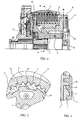
- clutch 10 is a vehicle clutch, in particular in the form of a motorcycle clutch.
- the clutch 10 has in addition to the at Conventional couplings provided parts that are not discussed here, since they are not required for the explanation of the principles of the invention, a friction system, in particular in the form of a disk pack 5, which is in operative connection with a driver 11.
- a spring 4 is provided which acts on the driver 11 via a bearing 8.
- the driver 11 is made in two parts and has an inner part or a hub 1 and an outer part 2, which is arranged rotatable relative to the inner part 1 by a defined angle of rotation.
- This twist angle is in Fig. 2 symbolized by the there drawn free space 7 between the cam of the inner part 1 and the outer part 2, wherein by way of example two cams 14 of the inner part 1 and two cams 15 of the outer part 2 are marked with the respective reference numerals.
- the spring 4 has a degressive spring characteristic.
- the storage 8 and the inner part 1 of the driver 11 are available with an over in Fig. 1 symbolized by the reference numeral 3 inclined plane or ramp arrangement in operative connection, wherein the inclined plane 3 in Fig. 3 is shown in detail.
- the inclined plane 3 has a ceremoniesnanördnung an inclined surface 12 of the bearing 8 and an inclined surface 13 of the inner part 1, as reflected by the detailed representation in Fig. 3 and detail B in Fig. 1 in detail results.
- the inclined plane or ramp arrangement 3 or its oblique surfaces 12 and 13 are in this case arranged obliquely to a plane surface, which in turn is perpendicular to the axis of rotation of the coupling 10.
- the driver 11 of the coupling 10 is designed in two parts, the inner part or the hub 1 of the driver 11 can be rotated relative to the outer part 2 by the defined angle 7 explained above.
- the off Fig. 2 apparent cams 14 and 15 of the inner and outer part 1 and 2 to each other and it can be transmitted the full clutch torque.
- the coupling 10 according to the invention is characterized by the combination of a mechanical ramp design (inclined plane 3) with the spring, in particular disk spring 4, which has a degressive characteristic.
- the pressure plate 9 of the clutch is not lifted, but the bearing 8 or the spring support of the plate spring 4 is displaced, whereby the spring 4 is further biased. Due to the degressive characteristic, however, the biasing force of the spring 4 on the pressure plate 9 and thus on the friction system 5, whereby the clutch 10 slipping easier and thus the thrust moment defined defined decreases.
- the pressure plate 9 is not moved, that is, there is no disturbing reaction to the driver's hand on the clutch lever, which has already been explained above.
- the inner part 1 is additionally or exclusively with a suitable actuator, preferably electrically or hydraulically, rotated relative to the outer part 2.
- the actuator adjusts the desired limited transmission torque over the defined angle.
- the action of the actuator may be accomplished, for example, by detecting the particular requirement, e.g. an ABS action, a throttle position, a wheel speed, etc., are initiated.
Abstract
Description
Die Erfindung betrifft eine Fahrzeugkupplung, insbesondere eine Motorradkupplung, gemäß dem Oberbegriff des Anspruches 1.The invention relates to a vehicle clutch, in particular a motorcycle clutch, according to the preamble of claim 1.
Fahrzeugdrehmomente, insbesondere von Motorrädern, sind in den letzten Jahren immer weiter angestiegen. Aus diesem Grund nehmen auch die Betätigungskräfte von Kupplungen immer weiter zu. Gleichzeitig richten sich Motorradhersteller vermehrt an weibliche Kunden, um ihren Marktanteil weiter auszubauen. Daraus ergibt sich die Notwendigkeit, mit geeigneten Maßnahmen den Komfort für den Fahrer bzw. die Fahrerin durch eine niedrige Kupplungshandkraft zu steigern.Vehicle torques, especially of motorcycles, have increased in recent years ever more. For this reason, the operating forces of clutches continue to increase. At the same time, motorcycle manufacturers are increasingly targeting female customers in order to further expand their market share. This results in the need to increase the comfort of the driver by a low clutch hand force with suitable measures.
Gleichzeitig führen die oben genannten hohen übertragbaren Momente der Kupplung zu dem Sicherheitsproblem, dass das Hinterrad im Schubbetrieb zu stempeln beginnen kann, wenn beispielsweise auf hohe Drehzahl zurückgeschaltet wird. Dies kann vom Prinzip her vermieden werden, wenn die Kupplung im Schubbetrieb geöffnet oder im Schlupf betrieben wird. Geübte Fahrer können dies durch fein dosiertes Ziehen des Kupplungshebels selbst tun. Um jedoch das Risiko für alle Fahrer zu minimieren, ist der Einsatz eines automatisch einsetzbaren Mechanismus wünschenswert, der die Kupplung im Schubbetrieb zumindest teilweise öffnet.At the same time, the above-mentioned high transmittable moments of the clutch cause the safety problem that the rear wheel can start to stamp in overrun when, for example, it is switched back to high speed. This can be avoided in principle, when the clutch is opened in overrun mode or operated in the slip. Experienced drivers can do this by finely dosed pulling the clutch lever itself. However, in order to minimize the risk for all drivers, the use of an automatically deployable mechanism is desirable, which opens the clutch in overrun at least partially.
Auf dem Markt bekannte Kupplungssysteme bringen im Schubbetrieb eine Zusatzkraft auf die Druckplatte bzw. den Kolben der Kupplung in entgegengesetzter Richtung zur Federkraft auf, um die Kupplung zu öffnen. Dabei wird durch das Abheben der Druckplatte immer eine Rückwirkung auf den Kupplungshebel erzeugt, was für den Fahrer als störend empfunden wird. Ferner arbeiten diese Kupplungssysteme mit zusätzlichen Federn, wodurch sich die Herstellkosten erhöhen.On the market known coupling systems bring in overrun an additional force on the pressure plate or the piston of the clutch in the opposite direction to the spring force to open the clutch. In this case, a reaction to the clutch lever is always generated by the lifting of the pressure plate, which is perceived as disturbing for the driver. Furthermore, these coupling systems work with additional springs, thereby increasing the manufacturing costs.
Aus der
Es ist daher Aufgabe der vorliegenden Erfindung, eine Fahrzeugkupplung, insbesondere Motorradkupplung, der im Oberbegriff des Anspruches 1 angegebenen Art zu schaffen, die auf einfache und für den Fahrer komfortbetonte Art und Weise ein zumindest teilweises Öffnen der Kupplung im Schubbetrieb ermöglicht.It is therefore an object of the present invention to provide a vehicle clutch, in particular motorcycle clutch, specified in the preamble of claim 1 way, which allows easy and comfortable for the driver way an at least partial opening of the clutch in overrun mode.
Die Lösung dieser Aufgabe erfolgt durch die Merkmale des Anspruchs 1.The solution of this object is achieved by the features of claim 1.
Erfindungsgemäß wird die degressive Federkennlinie der Kupplungsfeder in Kombination mit einer eine schiefe Ebene bildender Rampenanordnung zwischen der Lagerung der Feder und einem Innenteil des zweiteilig ausgeführten Mitnehmers genutzt, um eine Schubmomentbegrenzung ohne Rückwirkung auf die manuelle Kupplungsbetätigung zu erreichen.According to the degressive spring characteristic of the clutch spring is used in combination with an inclined plane forming ramp arrangement between the mounting of the spring and an inner part of the two-piece driver to achieve a thrust torque limit without affecting the manual clutch operation.
Zu den besonderen Vorteilen der erfindungsgemäßen Kupplung gehört eine geringe Komplexität und dadurch geringe Herstellkosten.Among the particular advantages of the coupling according to the invention is low complexity and thus low production costs.
Ferner ist ein sensibles Auslösen der Begrenzungsfunktion möglich, da die Abstützkraft mit dem Betätigungsweg abnimmt.Furthermore, a sensitive triggering of the limiting function is possible because the supporting force decreases with the actuating travel.
Schließlich wird die oben bereits erwähnte Vermeidung einer Rückwirkung auf die manuelle Betätigungskraft bzw. den Betätigungsweg erreicht.Finally, the above-mentioned avoidance of a reaction to the manual actuating force or the actuating travel is achieved.
Die Unteransprüche haben vorteilhafte Weiterbildungen der Erfindung zum Inhalt.The dependent claims have advantageous developments of the invention to the content.
Vom Prinzip her ist es möglich, zum Lösen der Kupplung das Fahrzeugschubmoment zu verwenden.In principle, it is possible to use the vehicle thrust to release the clutch.
In einer erfindungsgemäßen Variante kann die Kupplung auch parallel oder seriell aktiv umgesetzt werden Dabei ersetzt ein Aktuator das Fahrzeugschubmoment. In Verbindung mit der schiefen Ebene kann auf diese Weise jederzeit das übertragene Drehmoment minimiert werden. Z.B. ist bereits bei kleinem Fahrzeugschubmoment, welches auf glattem Untergrund bereits Probleme verursacht, eine Entkopplung unter Zuhilfenahme eines Aktuators ausreichend sicher möglich.In a variant according to the invention, the coupling can also be actively implemented in parallel or in series while being replaced an actuator the vehicle thrust moment. In conjunction with the inclined plane can be minimized in this way at any time the transmitted torque. For example, a decoupling with the aid of an actuator is sufficiently safe even at low vehicle thrust, which already causes problems on a smooth surface.
Zu den Vorteilen einer derartigen durch Aktuator erreichten aktiven Ausführung zählt ebenfalls eine geringe Komplexität und dadurch geringe Kosten.The advantages of such an active embodiment achieved by the actuator also include low complexity and thus low costs.
Auch bei diesem System wird eine Rückwirkung auf die Betätigungskraft bzw. den Betätigungsweg der Kupplung vermieden.In this system, a reaction to the operating force and the actuating travel of the clutch is avoided.
Obwohl die erfindungsgemäße Fahrzeugkupplung insbesondere bei Motorrädern besondere Vorteile zeigt, ist der Einsatz auch bei anderen durch Motoren angetriebenen Fahrzeugen (z.B. ATVs) möglich.Although the vehicle coupling according to the invention shows particular advantages, in particular in motorcycles, the use is also possible with other motor-driven vehicles (for example ATVs).
Weitere Einzelheiten, Vorteile und Merkmale der vorliegenden Erfindung ergeben sich aus nachfolgender Beschreibung der beigefügten Zeichnung anhand der Figuren. Es zeigt:
- Fig. 1
- eine Schnittdarstellung einer erfindungsgemäßen Kupplung,
- Fig. 2
- eine Schnittdarstellung der Kupplung gemäß
Fig. 1 entlang der Linie A-A inFig. 1 , und - Fig. 3
- das in
Fig. 1 angegebene Detail B der erfindungsgemäßen Kupplung.
- Fig. 1
- a sectional view of a coupling according to the invention,
- Fig. 2
- a sectional view of the coupling according to
Fig. 1 along the line AA inFig. 1 , and - Fig. 3
- this in
Fig. 1 specified detail B of the coupling according to the invention.
Die in
Ferner ist eine Feder 4 vorgesehen, die über eine Lagerung 8 auf den Mitnehmer 11 wirkt.Further, a spring 4 is provided which acts on the
Erfindungsgemäß ist der Mitnehmer 11 zweiteilig ausgeführt und weist ein Innenteil bzw. eine Nabe 1 und ein Außenteil 2 auf, das gegenüber dem Innenteil 1 um einen definierten Verdrehwinkel verdrehbar angeordnet ist. Dieser Verdrehwinkel ist in
Erfindungsgemäß weist die Feder 4 eine degressive Federkennlinie auf.According to the invention, the spring 4 has a degressive spring characteristic.
Die Lagerung 8 und das Innenteil 1 des Mitnehmers 11 stehen mit einer über in
Demgemäß weist die schiefe Ebene 3 eine Flächenanördnung einer Schrägfläche 12 der Lagerung 8 und einer Schrägfläche 13 des Innenteils 1 auf, wie sich dies durch die Detaildarstellung in
Da der Mitnehmer 11 der erfindungsgemäßen Kupplung 10 zweiteilig ausgeführt ist, kann das Innenteil bzw. die Nabe 1 des Mitnehmers 11 gegenüber dem Außenteil 2 um den zuvor erläuterten definierten Winkel 7 verdreht werden. Im Ruhezustand der Kupplung 10 und im Zugbetrieb liegen die aus
Im Schubbetrieb verdreht sich beispielsweise durch Ausnutzen des Fahrzeugschubmoments das Innenteil 1 gegenüber dem Außenteil 2 und es kommen nach Verdrehung um den definierten Verdrehwinkel 7 jeweils die Rückseiten der Nocken 14 bzw. 15 zur Anlage. Durch das Verdrehen wird über die schiefe Ebene 3 zwischen der Lagerung 8 und dem Innenteil 1 die Feder 4 mit ihrer degressiven Kennlinie weiter vorgespannt. Aufgrund der degressiven Kennlinie wird dadurch die Normalkraft der Feder 4 auf das Reibsystem 5 gesenkt, wodurch wiederum das übertragbare Schubmoment der Kupplung 10 abgesenkt wird. Dadurch kann die Kupplung 10 bereits bei niedrigen Schubmomenten rutschen. Dabei bleiben die Schnittstellen zur Betätigungseinheit, z.B. einem Nehmerzylinder 6 der Kupplung 10 unverändert, so dass sich keine Rückwirkungen auf die Fahrerhand am Kupplungshebel ergeben.In overrun operation, for example, by exploiting the vehicle thrust torque, the inner part 1 is rotated relative to the
Mit anderen Worten zeichnet sich die erfindungsgemäße Kupplung 10 durch die Verknüpfung einer mechanischen Rampenkonstruktion (schiefe Ebene 3) mit der Feder, insbesondere Tellerfeder 4, aus, die eine degressive Charakteristik hat. Dabei wird nicht die Druckplatte 9 der Kupplung abgehoben, sondern die Lagerung 8 bzw. das Federauflager der Tellerfeder 4 wird verschoben, wodurch die Feder 4 weiter vorgespannt wird. Durch die degressive Kennlinie sinkt dabei jedoch die Vorspannkraft der Feder 4 auf die Druckplatte 9 und damit auf das Reibsystem 5, wodurch die Kupplung 10 leichter durchrutschen und damit das Schubmoment definiert begrenzt werden kann.In other words, the
Zudem wird vorteilhafterweise bei der erfindungsgemäßen Kupplung 10 die Druckplatte 9 nicht bewegt, d.h., dass es keine störende Rückwirkung auf die Fahrerhand am Kupplungshebel gibt, was zuvor bereits erläutert wurde.In addition, advantageously, in the
In einer aktiven Ausführungsvariante der erfindungsgemäßen Kupplung 10, die in den Figuren nicht näher dargestellt ist, wird das Innenteil 1 zusätzlich oder ausschließlich mit einem geeigneten Aktuator, vorzugsweise elektrisch oder hydraulisch, gegenüber dem Außenteil 2 verdreht. Der Aktuator stellt dabei das gewünschte begrenzte Übertragungsmoment über den definierten Winkel ein. Die Aktion des Aktuators kann beispielsweise durch Erfassen des jeweiligen Erfordernisses, z.B. einer ABS-Aktion, einer Drosselklappenstellung, einer Raddrehzahl, usw., eingeleitet werden.In an active embodiment of the
Zur Ergänzung der Offenbarung wird neben der vorstehenden schriftlichen Beschreibung hiermit ausdrücklich auf die zeichnerische Darstellung gemäß der
- 11
- Innenteil/NabeInner part / hub
- 22
- Außenteilouter part
- 33
- Schiefe Ebene/RampenanordnungInclined plane / ramp arrangement
- 44
- Feder/TellerfederSpring / cup spring
- 55
- Reibsystemfriction system
- 66
- Nehmerzylinderslave cylinder
- 77
-
Freiraum gemäß
Fig. 2 zur Symbolisierung des DrehwinkelsFree space according toFig. 2 for symbolizing the angle of rotation - 88th
- Lagerung/FederauflagerStorage / spring support
- 99
- Druckplatteprinting plate
- 1010
- Kupplungclutch
- 1111
- Mitnehmertakeaway
- 1212
-
Schrägflächen der schiefen Ebene 3Inclined surfaces of the
inclined plane 3 - 1313
-
Schrägflächen der schiefen Ebene 3Inclined surfaces of the
inclined plane 3 - 1414
- Nockencam
- 1515
- Nockencam
Claims (8)
- A vehicle clutch (10), in particular a motorcycle clutch, comprising:- a friction system (5),- an engaging member (11) acting on the friction system (5), and- a spring (4) which is operatively connected to the engaging member (11) through a bearing (8) and which biases the friction system (5) through a pressure plate (9),characterized in that- the engaging member (11) is divided into an inner portion (1) and an outer portion (2) which may be twisted by a defined twisting angle (7) with respect to the inner portion (1),- the spring (4) has a degressive spring characteristic, and- the bearing (8) and the inner portion (1) are operatively connected by a ramp assembly (12, 13) constituting an inclined plane (3).
- The clutch of claim 1, characterized in that the inner portion (1) comprises cams (14) and the outer portion (2) comprises cams (15) which may be operatively interconnected for transmitting a clutch torque.
- The clutch of claim 2, characterized in that the cams (14, 15) abut at their front sides for fully transmitting the torque in an inoperative state and an engaged mode of the clutch.
- The clutch of claim 1 or 2, characterized in that, in an overrun condition of the clutch, the rear sides of the cams (14, 15) may abut by twisting the inner portion (1) with respect to the outer portion (2) by the defined twisting angle (7).
- The clutch of one of claims 1 to 4, characterized in that the twisting of the inner portion (1) with respect to the outer portion (2) may be generated by exploiting the overrun condition of the vehicle
- The clutch of one of claims 1 to 4, characterized in that an actuator is provided for twisting the inner portion (1) with respect to the outer portion (2).
- The clutch of claim 6, characterized in that the actuator is an electric or hydraulic actuator.
- The clutch of one of claims 1 to 7, characterized in that the spring (4) is configured as a disk spring.
Priority Applications (6)
| Application Number | Priority Date | Filing Date | Title |
|---|---|---|---|
| DE502005005638T DE502005005638D1 (en) | 2005-10-25 | 2005-10-25 | Vehicle clutch, especially motorcycle clutch |
| EP05023302A EP1780432B1 (en) | 2005-10-25 | 2005-10-25 | Vehicle clutch, in particular for motorcycle |
| AT05023302T ATE410611T1 (en) | 2005-10-25 | 2005-10-25 | VEHICLE CLUTCH, ESPECIALLY MOTORCYCLE CLUTCH |
| US11/552,308 US7753186B2 (en) | 2005-10-25 | 2006-10-24 | Vehicle clutch |
| JP2008537306A JP5129750B2 (en) | 2005-10-25 | 2006-10-30 | Vehicle clutch |
| PCT/ID2006/000006 WO2007049257A2 (en) | 2005-10-25 | 2006-10-30 | Vehicle clutch, particularly motorcycle clutch |
Applications Claiming Priority (1)
| Application Number | Priority Date | Filing Date | Title |
|---|---|---|---|
| EP05023302A EP1780432B1 (en) | 2005-10-25 | 2005-10-25 | Vehicle clutch, in particular for motorcycle |
Publications (2)
| Publication Number | Publication Date |
|---|---|
| EP1780432A1 EP1780432A1 (en) | 2007-05-02 |
| EP1780432B1 true EP1780432B1 (en) | 2008-10-08 |
Family
ID=36593763
Family Applications (1)
| Application Number | Title | Priority Date | Filing Date |
|---|---|---|---|
| EP05023302A Not-in-force EP1780432B1 (en) | 2005-10-25 | 2005-10-25 | Vehicle clutch, in particular for motorcycle |
Country Status (6)
| Country | Link |
|---|---|
| US (1) | US7753186B2 (en) |
| EP (1) | EP1780432B1 (en) |
| JP (1) | JP5129750B2 (en) |
| AT (1) | ATE410611T1 (en) |
| DE (1) | DE502005005638D1 (en) |
| WO (1) | WO2007049257A2 (en) |
Families Citing this family (9)
| Publication number | Priority date | Publication date | Assignee | Title |
|---|---|---|---|---|
| ATE410611T1 (en) * | 2005-10-25 | 2008-10-15 | Hoerbiger & Co | VEHICLE CLUTCH, ESPECIALLY MOTORCYCLE CLUTCH |
| DE502006006692D1 (en) * | 2006-02-02 | 2010-05-27 | Hoerbiger & Co | wrap spring |
| JP4785668B2 (en) * | 2006-08-02 | 2011-10-05 | 本田技研工業株式会社 | Multi-plate clutch |
| JP5183278B2 (en) * | 2008-04-03 | 2013-04-17 | 川崎重工業株式会社 | Friction clutch back torque reduction device |
| JP4929246B2 (en) * | 2008-07-31 | 2012-05-09 | 本田技研工業株式会社 | Multi-plate clutch |
| JP5680096B2 (en) | 2009-10-29 | 2015-03-04 | シェフラー テクノロジーズ アクチエンゲゼルシャフト ウント コンパニー コマンディートゲゼルシャフトSchaeffler Technologies AG & Co. KG | Wet clutch |
| EP3387281B1 (en) * | 2015-12-07 | 2020-08-26 | Norgren Automation Solutions, LLC | Anti-backlash clutch plates |
| CN105882408A (en) * | 2016-04-20 | 2016-08-24 | 常州大学 | Braking device capable of braking under condition of stepping on accelerator pedal by mistake as brake |
| CN107701613A (en) * | 2017-09-20 | 2018-02-16 | 顾梦君 | A kind of electromechanical equipment transmission clutch |
Family Cites Families (47)
| Publication number | Priority date | Publication date | Assignee | Title |
|---|---|---|---|---|
| US116396A (en) * | 1871-06-27 | Improvement in stove-grates | ||
| GB191514688A (en) | 1915-10-18 | 1916-05-04 | Humber Ltd | Improvements in Locking Mechanism for Change Speed Gearing and the like. |
| US2534034A (en) | 1941-02-20 | 1950-12-12 | Chrysler Corp | Clutch |
| GB774824A (en) | 1955-02-12 | 1957-05-15 | Vauxhall Motors Ltd | Improved interlock mechanisms for change-speed gearing |
| US3063529A (en) | 1959-09-25 | 1962-11-13 | Clark Equipment Co | Locking clutch |
| US3264894A (en) | 1963-10-04 | 1966-08-09 | Gen Motors Corp | Transmission controls |
| US3249190A (en) | 1964-05-11 | 1966-05-03 | Curtiss Wright Corp | Spring clutch with anti-fretting molybdenum coated surface |
| US3335835A (en) | 1965-05-27 | 1967-08-15 | Associated Spring Corp | Torque limiting spring clutch |
| US3444752A (en) | 1967-03-30 | 1969-05-20 | Borg Warner | Transmission shift control mechanism |
| US3424033A (en) | 1967-07-27 | 1969-01-28 | Ford Motor Co | Multiple ratio power shift transmission mechanism |
| US3527116A (en) | 1968-12-12 | 1970-09-08 | Gen Motors Corp | Transmission control |
| US3648537A (en) | 1970-11-12 | 1972-03-14 | Gen Motors Corp | Transmission control |
| DE2759188A1 (en) | 1977-12-31 | 1979-07-12 | Bosch Gmbh Robert | ELECTROMOTORIC ACTUATOR, IN PARTICULAR FOR A DEVICE FOR REGULATING THE SPEED OF A VEHICLE |
| JPS6053223A (en) * | 1983-09-01 | 1985-03-26 | Honda Motor Co Ltd | Clutch device |
| JPS60184721A (en) * | 1984-03-02 | 1985-09-20 | Suzuki Motor Co Ltd | Multiple-disc frictional clutch for motor-cycle |
| JPS60192129A (en) | 1984-03-09 | 1985-09-30 | Daikin Mfg Co Ltd | Liquid conveying device for rotary shaft |
| AT384086B (en) | 1984-09-07 | 1987-09-25 | Steyr Daimler Puch Ag | LIQUID FRICTION COUPLING |
| AT383195B (en) | 1985-07-02 | 1987-05-25 | Steyr Daimler Puch Ag | LIQUID FRICTION COUPLING |
| JPH0781594B2 (en) | 1985-08-31 | 1995-08-30 | 三菱自動車工業株式会社 | Power transmission device |
| DE3671078D1 (en) | 1985-11-26 | 1990-06-13 | Voith Gmbh J M | DISC CLUTCH. |
| US4741422A (en) | 1987-03-09 | 1988-05-03 | General Motors Corporation | Clutch assembly with a pressure balance chamber |
| JP3025008B2 (en) | 1989-06-10 | 2000-03-27 | ツァーンラトファブリク フリートリッヒシャフェン アクチエンゲゼルシャフト | Switching device for automobile transmission |
| DE9114528U1 (en) | 1991-11-22 | 1992-02-13 | Zahnradfabrik Friedrichshafen Ag, 7990 Friedrichshafen, De | |
| DE4239233C2 (en) | 1992-11-21 | 1997-05-22 | Daimler Benz Ag | Pressure fluid operated, axially engaging and disengaging friction clutch |
| JP3656270B2 (en) * | 1995-03-31 | 2005-06-08 | アイシン精機株式会社 | Connecting device |
| DE19609210C1 (en) | 1996-03-09 | 1997-07-17 | Daimler Benz Ag | Gear changing device for gearwheel variable gear |
| US6527116B1 (en) * | 1996-05-16 | 2003-03-04 | Regale Corporation | Shipping carton for glass bottles and pulp inserts for use therein and combination thereof |
| JP3291529B2 (en) | 1996-09-19 | 2002-06-10 | キヤノン株式会社 | Drive transmission device and image forming apparatus |
| DE29700807U1 (en) * | 1997-01-17 | 1997-02-27 | Joerg Schlechte Praezisionstei | Friction clutch for vehicles |
| JP3020054B2 (en) | 1998-03-25 | 2000-03-15 | 新日本ホイール工業株式会社 | Multi-plate friction clutch |
| DE19833378A1 (en) | 1998-07-24 | 1999-12-09 | Getrag Getriebe Zahnrad | Double clutch arrangement reduces the level of friction |
| DE10004195B4 (en) | 1999-09-30 | 2013-02-07 | Volkswagen Ag | Multiple clutch device |
| US6247569B1 (en) | 1999-12-15 | 2001-06-19 | Delphi Technologies, Inc. | Wrap spring clutch |
| FR2814517B1 (en) | 2000-09-22 | 2003-01-03 | Valeo | GEAR TRANSMISSION DEVICE, ESPECIALLY FOR A MOTOR VEHICLE |
| DE50001452D1 (en) | 2000-10-05 | 2003-04-17 | Ford Global Tech Inc | Double clutch for a transmission with two transmission input shafts |
| DE10109645A1 (en) | 2001-02-28 | 2002-09-05 | Volkswagen Ag | Shift lock device |
| US7014026B2 (en) * | 2001-06-07 | 2006-03-21 | Drussel Wilfley Design, L.L.C. | Manual/automatic pressure control mechanism for centrifugal clutch |
| DE10143834A1 (en) | 2001-09-07 | 2003-03-27 | Zf Sachs Ag | Multiple clutch system with wet running clutch device has hydraulic paths and operating medium paths formed in input hub |
| DE10146606A1 (en) | 2001-09-21 | 2003-04-10 | Zf Sachs Ag | Multiple clutch device with axially adjacent multi-plate clutch arrangements |
| JP2003139163A (en) | 2001-11-05 | 2003-05-14 | Nsk Warner Kk | Starting clutch |
| DE10163404B4 (en) | 2001-12-21 | 2009-06-04 | Zf Sachs Ag | Method for controlling a clutch system with at least one multi-disc clutch arrangement |
| US20040050643A1 (en) * | 2002-09-12 | 2004-03-18 | Krzesicki Richard M. | Clutch actuator |
| DE10323515A1 (en) | 2003-05-24 | 2004-12-23 | Dr.Ing.H.C. F. Porsche Ag | Coupling device and method for operating a multi-plate clutch |
| EP1630440B1 (en) | 2004-08-26 | 2008-04-09 | HOERBIGER Antriebstechnik GmbH | Hydraulic double clutch |
| DE602004024060D1 (en) | 2004-08-26 | 2009-12-24 | Hoerbiger & Co | Fluid coupling, in particular double clutch |
| ATE410611T1 (en) * | 2005-10-25 | 2008-10-15 | Hoerbiger & Co | VEHICLE CLUTCH, ESPECIALLY MOTORCYCLE CLUTCH |
| DE502006006692D1 (en) | 2006-02-02 | 2010-05-27 | Hoerbiger & Co | wrap spring |
-
2005
- 2005-10-25 AT AT05023302T patent/ATE410611T1/en not_active IP Right Cessation
- 2005-10-25 DE DE502005005638T patent/DE502005005638D1/en active Active
- 2005-10-25 EP EP05023302A patent/EP1780432B1/en not_active Not-in-force
-
2006
- 2006-10-24 US US11/552,308 patent/US7753186B2/en active Active
- 2006-10-30 JP JP2008537306A patent/JP5129750B2/en active Active
- 2006-10-30 WO PCT/ID2006/000006 patent/WO2007049257A2/en active Application Filing
Also Published As
| Publication number | Publication date |
|---|---|
| JP5129750B2 (en) | 2013-01-30 |
| DE502005005638D1 (en) | 2008-11-20 |
| JP2010508185A (en) | 2010-03-18 |
| US7753186B2 (en) | 2010-07-13 |
| US20070089961A1 (en) | 2007-04-26 |
| ATE410611T1 (en) | 2008-10-15 |
| WO2007049257A3 (en) | 2007-08-02 |
| EP1780432A1 (en) | 2007-05-02 |
| WO2007049257A2 (en) | 2007-05-03 |
Similar Documents
| Publication | Publication Date | Title |
|---|---|---|
| EP1780432B1 (en) | Vehicle clutch, in particular for motorcycle | |
| EP2912330B1 (en) | Driving pawl for a wear-compensating friction clutch | |
| DE102006024941A1 (en) | Four-wheel transmission system | |
| EP2971829B1 (en) | Clutch system | |
| DE202008016929U1 (en) | Drive for the motorized adjustment of an adjusting element of a motor vehicle | |
| DE19530873C2 (en) | Device for actuating the pressure plate on a coupling with reduced release force | |
| DE102016123777B4 (en) | Wear compensation device, clutch actuator unit having the wear compensation device, and vehicle having the clutch actuator unit | |
| EP3077689B1 (en) | Engaging/releasing system for a friction clutch | |
| EP2510260B1 (en) | Motor vehicle transmission having a controllable differential | |
| EP3665397B1 (en) | Self-reinforcing friction clutch having leaf springs | |
| EP2935927B1 (en) | Clutch device | |
| EP3755912A1 (en) | Friction clutch for a drivetrain of a motor vehicle having at least one leaf spring for boosting a pressing force of a spring device | |
| EP3123048B1 (en) | Path-controlled adjusting device for a friction clutch | |
| DE102010012627B4 (en) | Vehicle, in particular motorcycle, with a torque-limiting device | |
| DE102004032744A1 (en) | Stabilizer for a motor vehicle | |
| EP2368058B1 (en) | Starter motor disc having slip clutch | |
| EP1832772A2 (en) | Device for tolerance compensation for a coupling | |
| DE102013212429A1 (en) | Friction clutch for releasably connecting output shaft with drive train of motor car e.g. passenger car, has clutch cover comprising lid mount with which support ramp is brought into contact by actuation of clutch to relieve ramp ring | |
| WO2013167365A1 (en) | Plate spring for a friction clutch | |
| DE102017128882A1 (en) | Clutch assembly for a vehicle and vehicle with the clutch assembly | |
| DE102019133906B3 (en) | Hinge actuator for a torque coupling | |
| EP2828541B1 (en) | Lever element for a spring device of a friction clutch and corresponding friction clutch | |
| DE102020113220B4 (en) | Hinge actuator for a torque clutch | |
| DE102018108568B3 (en) | Compensation device for compensating an axial offset between an output part of a friction clutch and an input part of a transmission, and friction clutch | |
| DE102016213388A1 (en) | Coupling system for a hybrid motor vehicle powertrain with an actuating device deflecting the actuation force of a partial clutch |
Legal Events
| Date | Code | Title | Description |
|---|---|---|---|
| PUAI | Public reference made under article 153(3) epc to a published international application that has entered the european phase |
Free format text: ORIGINAL CODE: 0009012 |
|
| AK | Designated contracting states |
Kind code of ref document: A1 Designated state(s): AT BE BG CH CY CZ DE DK EE ES FI FR GB GR HU IE IS IT LI LT LU LV MC NL PL PT RO SE SI SK TR |
|
| AX | Request for extension of the european patent |
Extension state: AL BA HR MK YU |
|
| 17P | Request for examination filed |
Effective date: 20070703 |
|
| AKX | Designation fees paid |
Designated state(s): AT BE BG CH CY CZ DE DK EE ES FI FR GB GR HU IE IS IT LI LT LU LV MC NL PL PT RO SE SI SK TR |
|
| GRAP | Despatch of communication of intention to grant a patent |
Free format text: ORIGINAL CODE: EPIDOSNIGR1 |
|
| GRAS | Grant fee paid |
Free format text: ORIGINAL CODE: EPIDOSNIGR3 |
|
| GRAA | (expected) grant |
Free format text: ORIGINAL CODE: 0009210 |
|
| AK | Designated contracting states |
Kind code of ref document: B1 Designated state(s): AT BE BG CH CY CZ DE DK EE ES FI FR GB GR HU IE IS IT LI LT LU LV MC NL PL PT RO SE SI SK TR |
|
| REG | Reference to a national code |
Ref country code: GB Ref legal event code: FG4D Free format text: NOT ENGLISH |
|
| REG | Reference to a national code |
Ref country code: CH Ref legal event code: EP |
|
| REG | Reference to a national code |
Ref country code: IE Ref legal event code: FG4D Free format text: LANGUAGE OF EP DOCUMENT: GERMAN |
|
| REF | Corresponds to: |
Ref document number: 502005005638 Country of ref document: DE Date of ref document: 20081120 Kind code of ref document: P |
|
| PG25 | Lapsed in a contracting state [announced via postgrant information from national office to epo] |
Ref country code: SI Free format text: LAPSE BECAUSE OF FAILURE TO SUBMIT A TRANSLATION OF THE DESCRIPTION OR TO PAY THE FEE WITHIN THE PRESCRIBED TIME-LIMIT Effective date: 20081008 |
|
| NLV1 | Nl: lapsed or annulled due to failure to fulfill the requirements of art. 29p and 29m of the patents act | ||
| BERE | Be: lapsed |
Owner name: HOERBIGER ANTRIEBSTECHNIK G.M.B.H. Effective date: 20081031 |
|
| PG25 | Lapsed in a contracting state [announced via postgrant information from national office to epo] |
Ref country code: LT Free format text: LAPSE BECAUSE OF FAILURE TO SUBMIT A TRANSLATION OF THE DESCRIPTION OR TO PAY THE FEE WITHIN THE PRESCRIBED TIME-LIMIT Effective date: 20081008 Ref country code: BG Free format text: LAPSE BECAUSE OF FAILURE TO SUBMIT A TRANSLATION OF THE DESCRIPTION OR TO PAY THE FEE WITHIN THE PRESCRIBED TIME-LIMIT Effective date: 20090108 Ref country code: ES Free format text: LAPSE BECAUSE OF FAILURE TO SUBMIT A TRANSLATION OF THE DESCRIPTION OR TO PAY THE FEE WITHIN THE PRESCRIBED TIME-LIMIT Effective date: 20090119 |
|
| PG25 | Lapsed in a contracting state [announced via postgrant information from national office to epo] |
Ref country code: FI Free format text: LAPSE BECAUSE OF FAILURE TO SUBMIT A TRANSLATION OF THE DESCRIPTION OR TO PAY THE FEE WITHIN THE PRESCRIBED TIME-LIMIT Effective date: 20081008 Ref country code: NL Free format text: LAPSE BECAUSE OF FAILURE TO SUBMIT A TRANSLATION OF THE DESCRIPTION OR TO PAY THE FEE WITHIN THE PRESCRIBED TIME-LIMIT Effective date: 20081008 Ref country code: MC Free format text: LAPSE BECAUSE OF NON-PAYMENT OF DUE FEES Effective date: 20081031 Ref country code: PL Free format text: LAPSE BECAUSE OF FAILURE TO SUBMIT A TRANSLATION OF THE DESCRIPTION OR TO PAY THE FEE WITHIN THE PRESCRIBED TIME-LIMIT Effective date: 20081008 Ref country code: LV Free format text: LAPSE BECAUSE OF FAILURE TO SUBMIT A TRANSLATION OF THE DESCRIPTION OR TO PAY THE FEE WITHIN THE PRESCRIBED TIME-LIMIT Effective date: 20081008 Ref country code: IS Free format text: LAPSE BECAUSE OF FAILURE TO SUBMIT A TRANSLATION OF THE DESCRIPTION OR TO PAY THE FEE WITHIN THE PRESCRIBED TIME-LIMIT Effective date: 20090208 Ref country code: PT Free format text: LAPSE BECAUSE OF FAILURE TO SUBMIT A TRANSLATION OF THE DESCRIPTION OR TO PAY THE FEE WITHIN THE PRESCRIBED TIME-LIMIT Effective date: 20090218 |
|
| REG | Reference to a national code |
Ref country code: IE Ref legal event code: FD4D |
|
| PG25 | Lapsed in a contracting state [announced via postgrant information from national office to epo] |
Ref country code: DK Free format text: LAPSE BECAUSE OF FAILURE TO SUBMIT A TRANSLATION OF THE DESCRIPTION OR TO PAY THE FEE WITHIN THE PRESCRIBED TIME-LIMIT Effective date: 20081008 Ref country code: RO Free format text: LAPSE BECAUSE OF FAILURE TO SUBMIT A TRANSLATION OF THE DESCRIPTION OR TO PAY THE FEE WITHIN THE PRESCRIBED TIME-LIMIT Effective date: 20081008 Ref country code: IE Free format text: LAPSE BECAUSE OF FAILURE TO SUBMIT A TRANSLATION OF THE DESCRIPTION OR TO PAY THE FEE WITHIN THE PRESCRIBED TIME-LIMIT Effective date: 20081008 Ref country code: EE Free format text: LAPSE BECAUSE OF FAILURE TO SUBMIT A TRANSLATION OF THE DESCRIPTION OR TO PAY THE FEE WITHIN THE PRESCRIBED TIME-LIMIT Effective date: 20081008 |
|
| PLBE | No opposition filed within time limit |
Free format text: ORIGINAL CODE: 0009261 |
|
| STAA | Information on the status of an ep patent application or granted ep patent |
Free format text: STATUS: NO OPPOSITION FILED WITHIN TIME LIMIT |
|
| PG25 | Lapsed in a contracting state [announced via postgrant information from national office to epo] |
Ref country code: CZ Free format text: LAPSE BECAUSE OF FAILURE TO SUBMIT A TRANSLATION OF THE DESCRIPTION OR TO PAY THE FEE WITHIN THE PRESCRIBED TIME-LIMIT Effective date: 20081008 Ref country code: SE Free format text: LAPSE BECAUSE OF FAILURE TO SUBMIT A TRANSLATION OF THE DESCRIPTION OR TO PAY THE FEE WITHIN THE PRESCRIBED TIME-LIMIT Effective date: 20090108 |
|
| 26N | No opposition filed |
Effective date: 20090709 |
|
| PG25 | Lapsed in a contracting state [announced via postgrant information from national office to epo] |
Ref country code: SK Free format text: LAPSE BECAUSE OF FAILURE TO SUBMIT A TRANSLATION OF THE DESCRIPTION OR TO PAY THE FEE WITHIN THE PRESCRIBED TIME-LIMIT Effective date: 20081008 Ref country code: BE Free format text: LAPSE BECAUSE OF NON-PAYMENT OF DUE FEES Effective date: 20081031 |
|
| REG | Reference to a national code |
Ref country code: FR Ref legal event code: ST Effective date: 20090831 |
|
| PG25 | Lapsed in a contracting state [announced via postgrant information from national office to epo] |
Ref country code: AT Free format text: LAPSE BECAUSE OF NON-PAYMENT OF DUE FEES Effective date: 20081025 |
|
| REG | Reference to a national code |
Ref country code: CH Ref legal event code: PL |
|
| PG25 | Lapsed in a contracting state [announced via postgrant information from national office to epo] |
Ref country code: LU Free format text: LAPSE BECAUSE OF NON-PAYMENT OF DUE FEES Effective date: 20081025 Ref country code: HU Free format text: LAPSE BECAUSE OF FAILURE TO SUBMIT A TRANSLATION OF THE DESCRIPTION OR TO PAY THE FEE WITHIN THE PRESCRIBED TIME-LIMIT Effective date: 20090409 Ref country code: CY Free format text: LAPSE BECAUSE OF FAILURE TO SUBMIT A TRANSLATION OF THE DESCRIPTION OR TO PAY THE FEE WITHIN THE PRESCRIBED TIME-LIMIT Effective date: 20081008 |
|
| PG25 | Lapsed in a contracting state [announced via postgrant information from national office to epo] |
Ref country code: TR Free format text: LAPSE BECAUSE OF FAILURE TO SUBMIT A TRANSLATION OF THE DESCRIPTION OR TO PAY THE FEE WITHIN THE PRESCRIBED TIME-LIMIT Effective date: 20081008 |
|
| PG25 | Lapsed in a contracting state [announced via postgrant information from national office to epo] |
Ref country code: GR Free format text: LAPSE BECAUSE OF FAILURE TO SUBMIT A TRANSLATION OF THE DESCRIPTION OR TO PAY THE FEE WITHIN THE PRESCRIBED TIME-LIMIT Effective date: 20090109 Ref country code: LI Free format text: LAPSE BECAUSE OF NON-PAYMENT OF DUE FEES Effective date: 20091031 Ref country code: CH Free format text: LAPSE BECAUSE OF NON-PAYMENT OF DUE FEES Effective date: 20091031 |
|
| PG25 | Lapsed in a contracting state [announced via postgrant information from national office to epo] |
Ref country code: GB Free format text: LAPSE BECAUSE OF NON-PAYMENT OF DUE FEES Effective date: 20091025 |
|
| PG25 | Lapsed in a contracting state [announced via postgrant information from national office to epo] |
Ref country code: FR Free format text: LAPSE BECAUSE OF NON-PAYMENT OF DUE FEES Effective date: 20081031 |
|
| PGFP | Annual fee paid to national office [announced via postgrant information from national office to epo] |
Ref country code: IT Payment date: 20171024 Year of fee payment: 13 |
|
| PGFP | Annual fee paid to national office [announced via postgrant information from national office to epo] |
Ref country code: DE Payment date: 20171229 Year of fee payment: 13 |
|
| REG | Reference to a national code |
Ref country code: DE Ref legal event code: R119 Ref document number: 502005005638 Country of ref document: DE |
|
| PG25 | Lapsed in a contracting state [announced via postgrant information from national office to epo] |
Ref country code: DE Free format text: LAPSE BECAUSE OF NON-PAYMENT OF DUE FEES Effective date: 20190501 |
|
| PG25 | Lapsed in a contracting state [announced via postgrant information from national office to epo] |
Ref country code: IT Free format text: LAPSE BECAUSE OF NON-PAYMENT OF DUE FEES Effective date: 20181025 |