EP1832772A2 - Device for tolerance compensation for a coupling - Google Patents
Device for tolerance compensation for a coupling Download PDFInfo
- Publication number
- EP1832772A2 EP1832772A2 EP07003725A EP07003725A EP1832772A2 EP 1832772 A2 EP1832772 A2 EP 1832772A2 EP 07003725 A EP07003725 A EP 07003725A EP 07003725 A EP07003725 A EP 07003725A EP 1832772 A2 EP1832772 A2 EP 1832772A2
- Authority
- EP
- European Patent Office
- Prior art keywords
- clutch
- input
- coupling
- connecting element
- back plate
- Prior art date
- Legal status (The legal status is an assumption and is not a legal conclusion. Google has not performed a legal analysis and makes no representation as to the accuracy of the status listed.)
- Withdrawn
Links
Images


Classifications
-
- F—MECHANICAL ENGINEERING; LIGHTING; HEATING; WEAPONS; BLASTING
- F16—ENGINEERING ELEMENTS AND UNITS; GENERAL MEASURES FOR PRODUCING AND MAINTAINING EFFECTIVE FUNCTIONING OF MACHINES OR INSTALLATIONS; THERMAL INSULATION IN GENERAL
- F16D—COUPLINGS FOR TRANSMITTING ROTATION; CLUTCHES; BRAKES
- F16D23/00—Details of mechanically-actuated clutches not specific for one distinct type
- F16D23/12—Mechanical clutch-actuating mechanisms arranged outside the clutch as such
- F16D23/14—Clutch-actuating sleeves or bearings; Actuating members directly connected to clutch-actuating sleeves or bearings
- F16D23/148—Guide-sleeve receiving the clutch release bearing
-
- F—MECHANICAL ENGINEERING; LIGHTING; HEATING; WEAPONS; BLASTING
- F16—ENGINEERING ELEMENTS AND UNITS; GENERAL MEASURES FOR PRODUCING AND MAINTAINING EFFECTIVE FUNCTIONING OF MACHINES OR INSTALLATIONS; THERMAL INSULATION IN GENERAL
- F16D—COUPLINGS FOR TRANSMITTING ROTATION; CLUTCHES; BRAKES
- F16D13/00—Friction clutches
- F16D13/58—Details
- F16D13/75—Features relating to adjustment, e.g. slack adjusters
- F16D13/752—Features relating to adjustment, e.g. slack adjusters the adjusting device being located in the actuating mechanism arranged outside the clutch
-
- F—MECHANICAL ENGINEERING; LIGHTING; HEATING; WEAPONS; BLASTING
- F16—ENGINEERING ELEMENTS AND UNITS; GENERAL MEASURES FOR PRODUCING AND MAINTAINING EFFECTIVE FUNCTIONING OF MACHINES OR INSTALLATIONS; THERMAL INSULATION IN GENERAL
- F16D—COUPLINGS FOR TRANSMITTING ROTATION; CLUTCHES; BRAKES
- F16D2300/00—Special features for couplings or clutches
- F16D2300/12—Mounting or assembling
Definitions
- a clutch as eg in the DE 10 2005 003 505 A1 is typically installed between an engine and a transmission to selectively establish and interrupt power flow between the engine and the transmission.
- Both the engine and the transmission are usually installed at a fixed position in an assembly such as a vehicle, wherein a reaction plate of the clutch is connected to a crankshaft of the engine, and a clutch disc of the clutch is connected to the transmission, wherein the clutch disc at engaged clutch is pressed against the counter pressure disc.
- a flywheel such as a so-called dual-mass flywheel is arranged between the crankshaft of the engine and the counter-pressure plate.
- the tolerance compensation device is suitable for a clutch which has an input element and an output element and optionally transmits and interrupts a rotation of the input element to the output element.
- the tolerance compensation device has a connecting member coaxially rotatably supported with respect to the input member, a back plate coaxially supported on the connecting member, axially slidable along the connecting member, and an external device; in particular, a gear can be fastened, and a fixing device which fixes the back plate at an axial position with respect to the connecting member when the connecting member is rotated relative to the back plate.
- the hollow shaft 10 is made of a plastic material, and the cutting edge 20 may intersect with a forced rotation of the tubular extension 18 relative to the hollow shaft 10 in the projections 22 of the hollow shaft 10 in the circumferential direction.
- a suitable stop member (not shown) may be provided which stops the penetrating cutting edges 20 at a predetermined position in the circumferential direction.
- the recess 16 in the tab-like extension 15 of the outer race 13 of the third roller bearing 11 with the nose 17 on the hollow shaft 10 is engaged, so that a relative rotation of the hollow shaft 10 to cover 12 is prevented.
- the clutch with the integrated release system is now mounted, for example, in a vehicle, then the clutch and the release system are inserted as a unit in a clutch bell of a transmission. Then, the back plate 19 is connected to the transmission of the vehicle. Subsequently, the transmission and the clutch attached thereto are connected to the dual-mass flywheel from the crankshaft of the vehicle.
- the lug 17 of the hollow shaft 10 is sheared off by the recess 16 in the outer race 13.
- the hollow shaft 10 and the rear plate 19 connected thereto can freely rotate relative to the cover 12 via the third roller bearing 11. Even if the cutting edges 20 have cut into the projections 22, the axial position of the hollow shaft 10 with respect to the back plate 19 remains, and the biasing force in the dual-mass flywheel is maintained.
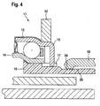
- Fig. 4 shows a detail of a device for tolerance compensation for a clutch according to a second embodiment of the present invention.
- the second embodiment differs from the first embodiment in the configuration of the fixing device.
- the same or similar components with respect to the first embodiment are provided with the same reference numerals.
- the advantage of the second embodiment over the first embodiment is that the threaded engagement between the internal thread 24 and the external thread 25 is releasable again, whereas the fixing by means of the cutting edges 20 and projections 22 in the first embodiment is irreversible.
- the first embodiment has the advantage that the tolerances and the bias of the dual mass flywheel can be set very accurately, whereas the threaded engagement between the internal thread 24 and the external thread 25 in the second embodiment allows only a displacement of the hollow shaft 10 in the thread pitch, i. with a tolerance of about 1 mm.
Abstract
Description
Die vorliegende Erfindung bezieht sich auf eine Vorrichtung zum Toleranzausgleich für eine Kupplung und auf eine Kupplung, die mit der Vorrichtung versehen ist.The present invention relates to a tolerance compensation device for a clutch and to a clutch provided with the device.
Eine Kupplung, wie sie z.B. in der
Beim Einbau der Kupplung können jedoch Verschiebungen und Toleranzen entstehen, die eine Last auf das Zweimassenschwungrad oder auch auf die Kupplungsscheibe aufbringen.However, when installing the clutch, shifts and tolerances can occur which apply a load to the dual mass flywheel or to the clutch disc.
Es ist die Aufgabe der vorliegenden Erfindung, eine Vorrichtung zum Toleranzausgleich für eine Kupplung und eine Kupplung vorzusehen, bei denen auch nach dem Einbau der Kupplung z.B. in ein Fahrzeug Toleranzen ausgeglichen werden können.It is the object of the present invention to provide a device for tolerance compensation for a clutch and a clutch in which, even after installation of the clutch, e.g. can be compensated in a vehicle tolerances.
Diese Aufgabe wird durch die Vorrichtung zum Toleranzausgleich mit den Merkmalen des Anspruchs 1 gelöst. Vorteilhafte Weiterbildungen sind in den abhängigen Ansprüchen definiert.This object is achieved by the device for tolerance compensation with the features of claim 1. Advantageous developments are defined in the dependent claims.
Die erfindungsgemäße Vorrichtung zum Toleranzausgleich ist für eine Kupplung geeignet, die ein Eingangselement und ein Ausgangselement aufweist und eine Drehung des Eingangselements zu dem Ausgangselement wahlweise überträgt und unterbricht. Die Vorrichtung zum Toleranzausgleich hat ein Verbindungselement, das hinsichtlich des Eingangselements koaxial drehbar gestützt ist, eine Rückplatte, die koaxial an dem Verbindungselement gestützt ist, axial entlang des Verbindungselements verschiebbar ist und an einer externen Vorrichtung, insbesondere ein Getriebe befestigbar ist, und eine Fixiervorrichtung, die die Rückplatte an einer axialen Position hinsichtlich des Verbindungselements fixiert, wenn das Verbindungselement relativ zu der Rückplatte verdreht wird.The tolerance compensation device according to the invention is suitable for a clutch which has an input element and an output element and optionally transmits and interrupts a rotation of the input element to the output element. The tolerance compensation device has a connecting member coaxially rotatably supported with respect to the input member, a back plate coaxially supported on the connecting member, axially slidable along the connecting member, and an external device; in particular, a gear can be fastened, and a fixing device which fixes the back plate at an axial position with respect to the connecting member when the connecting member is rotated relative to the back plate.
In vorteilhafter Weise erfordert die Vorrichtung zum Toleranzausgleich keinen zusätzlichen axialen Raum und nur einen kleinen radialen Raum. Der Vorrichtung arbeitet in vorteilhafter Weise vollautomatisch, sodass der Einbau der Kupplung erleichtert ist.Advantageously, the device for tolerance compensation requires no additional axial space and only a small radial space. The device works fully automatically in an advantageous manner, so that the installation of the coupling is facilitated.
Weitere Merkmale und Vorteile der vorliegenden Erfindung werden aus der folgenden Beschreibung von Ausführungsbeispielen ersichtlich. Dabei zeigen
- Fig. 1 schematisch eine Längsschnittansicht einer Vorrichtung zum Toleranzausgleich für eine Kupplung gemäß einem ersten Ausführungsbeispiel der vorliegenden Erfindung;
- Fig. 2 eine Einzelheit der Vorrichtung zum Toleranzausgleich für eine Kupplung gemäß der Fig. 1;
- Fig. 3 eine Querschnittsansicht der Vorrichtung zum Toleranzausgleich für eine Kupplung gemäß den Figuren 1 und 2;
- Fig. 4 eine Einzelheit einer Vorrichtung zum Toleranzausgleich für eine Kupplung gemäß einem zweiten Ausführungsbeispiel der vorliegenden Erfindung.
- Fig. 1 shows schematically a longitudinal sectional view of a device for tolerance compensation for a clutch according to a first embodiment of the present invention;
- FIG. 2 shows a detail of the device for tolerance compensation for a coupling according to FIG. 1; FIG.
- 3 shows a cross-sectional view of the device for tolerance compensation for a coupling according to FIGS. 1 and 2;
- Fig. 4 shows a detail of a device for tolerance compensation for a clutch according to a second embodiment of the present invention.
Die Fig. 1 zeigt schematisch eine Längsschnittansicht einer Vorrichtung zum Toleranzausgleich für eine Kupplung gemäß einem ersten Ausführungsbeispiel der vorliegenden Erfindung, und die Fig. 2 zeigt eine Einzelheit der Vorrichtung zum Toleranzausgleich für eine Kupplung gemäß der Fig. 1.1 shows schematically a longitudinal sectional view of a device for tolerance compensation for a clutch according to a first embodiment of the present invention, and FIG. 2 shows a detail of the device for tolerance compensation for a clutch according to FIG. 1.
Die Kupplung gemäß dem ersten Ausführungsbeispiel ist eine Reibungskupplung mit zwei Kupplungsscheiben 1, von denen in Fig. 1 nur eine Kupplungsscheibe 1 schematisch gezeigt ist. Diese Kupplungen sind auch als Doppel-Kupplungen allgemein bekannt. Im Normalzustand ist die Kupplung eingerückt, indem ein erstes und ein zweites Hebelelement 2, 3 gemäß der Fig. 1 im Gegenuhrzeigersinn in einer Einrückrichtung mittels nicht gezeigter Federn vorgespannt werden und die beiden Kupplungsscheiben 1 an ein Eingangselement in Gestalt einer Gegendruckscheibe 4 drücken. Die Gegendruckscheibe 4 ist über ihre radial äußere Seite mit einem Schwungrad (nicht gezeigt) und einer Kurbelwelle (nicht gezeigt) einer Kraftmaschine verbindbar. Das Schwungrad ist vorzugsweise als ein allgemein bekanntes Zweimassenschwungrad ausgeführt. Das Zweimassenschwungrad verfügt im Wesentlichen über eine innere Ringscheibe und eine äußere Ringscheibe, die über eine in Umfangsrichtung wirkende Feder miteinander verbunden sind. In vorteilhafter Weise hat das Schwingungssystem Kurbelwelle-Schwungrad-Kupplung dadurch einen besseren Gleichförmigkeitsgrad.The clutch according to the first embodiment is a friction clutch with two clutch plates 1, of which in Fig. 1, only one clutch disc 1 is shown schematically. These couplings are also well known as double couplings. In the normal state, the clutch is engaged by a first and a second lever element 2, 3 are biased in a direction of engagement by means of springs not shown in FIG. 1 in a counterclockwise direction and press the two clutch plates 1 to an input element in the form of a reaction plate 4. The counter-pressure disk 4 is on its radially outer side connectable to a flywheel (not shown) and a crankshaft (not shown) of an engine. The flywheel is preferably designed as a well-known dual-mass flywheel. The dual-mass flywheel essentially has an inner annular disk and an outer annular disk, which are connected to one another via a spring acting in the circumferential direction. Advantageously, the crankshaft flywheel clutch vibration system thereby has a better degree of uniformity.
Die Kupplungsscheibe 1 gelangt an ihrer radial äußeren Seite bei eingerückter Kupplung mit der Gegendruckscheibe 4 in Eingriff. Die Kupplungsscheibe 1 wiederum ist an ihrer radial inneren Seite mit einem Ausgangselement in Gestalt einer Getriebewelle 5 koppelbar. Bei eingerückter Kupplung ist somit ein Kraftfluss zwischen der Kraftmaschine und dem Getriebe hergestellt.The clutch disc 1 engages on its radially outer side with the clutch engaged with the counter-pressure disk 4 into engagement. The clutch disc 1 in turn can be coupled on its radially inner side with an output element in the form of a transmission shaft 5. When the clutch is engaged thus a power flow between the engine and the transmission is made.
Ein Ausrücksystem der Kupplung schwenkt die beiden Hebelelemente 2, 3 im Uhrzeigersinn gemäß der Fig. 1, d.h. in einer Ausrückrichtung, sodass der Eingriff zwischen der Kupplungsscheibe 1 und der Gegendruckscheibe 4 gelöst wird. Das Ausrücksystem besteht aus einer ersten Schiebehülse 6, die das erste Hebelelement 2 über ein erstes Wälzlager 8 betätigt, und einer zweiten Schiebehülse 7, die das zweite Hebelelement 3 über ein zweites Wälzlager 9 betätigt. Die erste und die zweite Schiebehülse 6, 7 sind in einer Ausrückrichtung (nach links gemäß der Fig. 1) verschiebbar, wodurch die Kupplung ausgerückt wird.A release system of the clutch pivots the two lever members 2, 3 in the clockwise direction of FIG. 1, i. in a disengaging direction, so that the engagement between the clutch disc 1 and the reaction plate 4 is released. The disengagement system consists of a first sliding
Die Vorrichtung zum Toleranzausgleich für eine Kupplung wird im Einzelnen unter Bezugnahme auf die Figuren 2 und 3 beschrieben. Ein Verbindungselement in Gestalt einer Hohlwelle 10 ist über ein drittes Wälzlager 11 drehbar an einer Abdeckung 12 gestützt, die mit der Gegendruckscheibe 4 verbunden ist und das Innere der Kupplung mit den darin angeordneten Kupplungsscheiben 1 abdeckt. Ein äußerer Laufring 13 des dritten Wälzlagers 11 ist an der Abdeckung 12 befestigt, und ein innerer Laufring 14 des dritten Wälzlagers 11 ist an der Hohlwelle 10 befestigt. Wie dies in den Figuren 2 und 3 gezeigt ist, hat der äußere Laufring 13 einen lappenartigen Fortsatz 15, der sich zu der Hohlwelle 10 erstreckt. Am Ende des lappenartigen Fortsatzes 15 ist eine Aussparung 16, die mit einer Nase 17 im Eingriff ist, die entsprechend an der Hohlwelle 10 vorgesehen ist. Die Aussparungen 16 und die Nase 17 bilden eine lösbare Drehsperre, die eine relative Drehung der Hohlwelle 10 zu der Abdeckung 12 unterbindet. Die Nase 17 hat eine bestimmte Scherfestigkeit, sodass eine relative Drehung der Hohlwelle 10 zu der Abdeckung 12 ermöglicht wird, falls die Nase 17 durch die Aussparung abgeschert wird.The device for tolerance compensation for a clutch will be described in detail with reference to Figures 2 and 3. A connecting element in the form of a
Über die Hohlwelle 10 ist eine röhrenartige Erweiterung 18 einer Rückplatte 19 geschoben. Die röhrenartige Erweiterung 18 ist axial entlang der Hohlwelle 10 verschiebbar.About the
An dem Ende der röhrenartigen Erweiterung 18 sind in mehreren Intervallen Fixiervorrichtungen in Gestalt von Schneidkanten 20 angeordnet, die radial nach innen zur Hohlwelle 10 gerichtet sind. Die Schneidkanten 20 sind in entsprechende Nuten 21 der Hohlwelle 10 axial verschiebbar angeordnet, wie dies in der Fig. 3 ersichtlich ist. Zwischen den Nuten 21 befinden sich Vorsprünge 22 der Hohlwelle 10.At the end of the
Die Hohlwelle 10 ist aus einem Kunststoff gefertigt, und die Schneidkante 20 kann sich bei einer erzwungenen Drehung der röhrenartigen Erweiterung 18 relativ zu der Hohlwelle 10 in die Vorsprünge 22 der Hohlwelle 10 in Umfangsrichtung hinein schneiden. Vorzugsweise kann ein geeignetes Stoppelement (nicht gezeigt) vorgesehen sein, das die eindringenden Schneidkanten 20 an einer vorbestimmten Position in Umfangsrichtung stoppt.The
An dem zum dritten Wälzlager 11 entgegengesetzten Ende der Hohlwelle 10 ist eine Feder 23 angeordnet, die einerseits am Ende der Hohlwelle 10 befestigt ist und andererseits mit der Rückplatte 19 im Eingriff ist. Die Feder 23 spannt die Hohlwelle 10 mit einer vorbestimmten Vorspannkraft bezüglich der Rückplatte 19 in der axialen Richtung vor, d.h. im Falle der Fig. 1 nach links. Alternativ kann die Feder 23 die Hohlwelle 10 in der axialen Richtung bezüglich der Rückplatte 19 nach rechts gemäß der Fig. 1 vorspannen. Vorzugsweise hat die Feder 23 eine relativ flach ansteigende Federkurve, d.h. die Federkraft ändert sich kaum entlang des Verstellwegs der Feder 23.At the end of the
Die Funktion der Vorrichtung bzw. des Mechanismus zum Toleranzausgleich für eine Kupplung wird nun beschrieben.The function of the device or mechanism for tolerance compensation for a clutch will now be described.
Im Auslieferungszustand der Kupplung ist die Aussparung 16 im lappenartigen Fortsatz 15 des äußeren Laufrings 13 des dritten Wälzlagers 11 mit der Nase 17 an der Hohlwelle 10 im Eingriff, sodass eine relative Drehung der Hohlwelle 10 zur Abdeckung 12 unterbunden wird. Wenn die Kupplung mit dem integrierten Ausrücksystem nun z.B. in ein Fahrzeug montiert wird, dann werden die Kupplung und das Ausrücksystem als eine Einheit in eine Kupplungsglocke eines Getriebes eingefügt. Dann wird die Rückplatte 19 mit dem Getriebe des Fahrzeugs verbunden. Anschließend werden das Getriebe und die daran befestigte Kupplung mit dem Zweimassenschwungrad seitens der Kurbelwelle des Fahrzeugs verbunden. Bei dieser Montagestufe ist die Hohlwelle 10 innerhalb der röhrenartigen Erweiterung 18 der Rückplatte 19 frei verschiebbar, wobei sich zwischen der Federkraft des Zweimassenschwungrads und der Vorspannkraft der Feder 23 ein Gleichgewicht einstellt. Der Kraftfluss der Federvorspannung verläuft von der Feder 23 über die Hohlwelle 10, das dritte Wälzlager 11, die Abdeckung 12 und die Gegendruckplatte 4 zum Zweimassenschwungrad. Somit erhält die Flexplatte eine vorbestimmte Vorspannung in der axialen Richtung entsprechend der Feder 23. Anschließend wird der Motor betrieben, und die Kurbelwelle wird gedreht, sodass sich bei eingerückter Kupplung auch die Gegendruckscheibe 4 und die damit verbundene Abdeckung 12 drehen. Da die Aussparung 16 in dem äußeren Laufring 13 des dritten Lagers 11 mit der Nase 17 der Hohlwelle 10 im Eingriff ist, wird auch die Hohlwelle 10 gedreht. Da die Rückplatte 19 bereits an dem Getriebe befestigt wurde, werden die Hohlwelle 10 und die Rückplatte 19 zueinander verdreht. Infolgedessen schneiden sich die Schneidkanten 20 der röhrenartigen Erweiterung 18 in die Vorsprünge 22 der Hohlwelle 10 hinein, bis sie durch das Stoppelement (nicht gezeigt) gestoppt werden. Dadurch wird die Hohlwelle 10 an der röhrenartigen Erweiterung 18 fixiert.In the state of delivery of the clutch, the
Wenn das zwischen der Abdeckung 12 und der Hohlwelle 10 übertragene Drehmoment schließlich eine Scherfestigkeit der Nase 17 der Hohlwelle 10 überschreitet, dann wird die Nase 17 der Hohlwelle 10 durch die Aussparung 16 im äußeren Laufring 13 abgeschert. Dadurch können sich die Hohlwelle 10 und die damit verbundene Rückplatte 19 über das dritte Wälzlager 11 relativ zu der Abdeckung 12 frei drehen. Auch wenn sich die Schneidkanten 20 in die Vorsprünge 22 hinein geschnitten haben, bleibt die axiale Position der Hohlwelle 10 bezüglich der Rückplatte 19 bestehen, und die Vorspannkraft in dem Zweimassenschwungrad wird aufrechterhalten.If the torque transmitted between the
Die Fig. 4 zeigt eine Einzelheit einer Vorrichtung zum Toleranzausgleich für eine Kupplung gemäß einem zweiten Ausführungsbeispiel der vorliegenden Erfindung. Das zweite Ausführungsbeispiel unterscheidet sich von dem ersten Ausführungsbeispiel in der Gestaltung der Fixiervorrichtung. Gleiche oder ähnliche Bauelemente hinsichtlich des ersten Ausführungsbeispieles sind mit denselben Bezugszeichen versehen.Fig. 4 shows a detail of a device for tolerance compensation for a clutch according to a second embodiment of the present invention. The second embodiment differs from the first embodiment in the configuration of the fixing device. The same or similar components with respect to the first embodiment are provided with the same reference numerals.
Während das erste Ausführungsbeispiel Schneidkanten 20 und Vorsprünge 22 aufweist, so hat das zweite Ausführungsbeispiel stattdessen ein am Ende der röhrenartigen Erweiterung 18 der Rückplatte vorgesehenes Innengewinde 24 und ein an der entsprechenden Stelle der Hohlwelle 10 vorgesehenes Außengewinde 25. Das Innengewinde 24 hat eine geringfügig unterschiedliche Gewindesteigung als das Außengewinde 25.While the first embodiment has cutting
Wenn die Hohlwelle 10 relativ zu der röhrenartigen Erweiterung 18 verdreht wird, dann gelangt das Innengewinde 24 mit dem Außengewinde 25 in einen Gewindeeingriff, wobei sich das Außengewinde 25 in dem Innengewinde 24 verklemmt, sodass die Hohlwelle 10 an der röhrenartigen Erweiterung 18 fixiert wird.When the
Der Vorteil des zweiten Ausführungsbeispieles gegenüber dem ersten Ausführungsbeispiel liegt darin, dass der Gewindeeingriff zwischen dem Innengewinde 24 und dem Außengewinde 25 wieder lösbar ist, wohingegen die Fixierung mittels der Schneidkanten 20 und Vorsprünge 22 bei dem ersten Ausführungsbeispiel irreversibel ist. Andererseits hat das erste Ausführungsbeispiel den Vorteil, dass die Toleranzen und die Vorspannung des Zweimassenschwungrads sehr genau eingestellt werden können, wohingegen der Gewindeeingriff zwischen dem Innengewinde 24 und dem Außengewinde 25 bei dem zweiten Ausführungsbeispiel nur eine Verschiebung der Hohlwelle 10 im Rahmen der Gewindesteigung ermöglicht, d.h. mit einer Toleranz von etwa 1 mm.The advantage of the second embodiment over the first embodiment is that the threaded engagement between the
Die dargestellten Ausführungsbeispiele können folgendermaßen abgewandelt werden: Die Feder 23 kann weggelassen werden, wodurch die Toleranz und ggf. eine Vorspannkraft auf das Zweimassenschwungrad manuell einstellbar sind. Die Erfindung funktioniert auch bei einer kinematischen Umkehr der Kupplung, d.h. wenn das Eingangselement und das Ausgangselement der Kupplung kinematisch vertauscht werden.The illustrated embodiments may be modified as follows: The
- 11
- Kupplungsscheibeclutch disc
- 22
- Erstes HebelelementFirst lever element
- 33
- Zweites HebelelementSecond lever element
- 44
- GegendruckscheibeReaction plate
- 55
- Getriebewellegear shaft
- 66
- Erste SchiebehülseFirst sliding sleeve
- 77
- Zweite SchiebehülseSecond sliding sleeve
- 88th
- Erstes WälzlagerFirst rolling bearing
- 99
- Zweites WälzlagerSecond rolling bearing
- 1010
- Hohlwellehollow shaft
- 1111
- Drittes WälzlagerThird rolling bearing
- 1212
- Abdeckungcover
- 1313
- Äußerer LaufringOuter race
- 1414
- Innerer LaufringInner race
- 1515
- Lappenartiger FortsatzLobe-like extension
- 1616
- Aussparungrecess
- 1717
- Nasenose
- 1818
- Röhrenartige ErweiterungTubular extension
- 1919
- Rückplattebackplate
- 2020
- Schneidkantecutting edge
- 2121
- Nutgroove
- 2222
- Vorsprunghead Start
- 2323
- Federfeather
- 2424
- Innengewindeinner thread
- 2525
- Außengewindeexternal thread
Claims (9)
gekennzeichnet durch
ein Verbindungselement (10), das hinsichtlich des Eingangselements (4) koaxial drehbar gestützt ist,
eine Rückplatte (19), die koaxial an dem Verbindungselement (10) gestützt ist, axial entlang des Verbindungselements (10) verschiebbar ist und an einer externen Vorrichtung, insbesondere ein Getriebe befestigbar ist, und
eine Fixiervorrichtung (20, 22), die die Rückplatte (19) an einer axialen Position hinsichtlich des Verbindungselements (10) fixiert, wenn das Verbindungselement (10) relativ zu der Rückplatte (19) verdreht wird.Device for tolerance compensation for a clutch, the clutch having an input element (4) and an output element (5) and selectively transmitting and interrupting rotation of the input element (4) to the output element (5),
marked by
a connecting member (10) coaxially rotatably supported with respect to the input member (4),
a back plate (19) coaxially supported on the connecting member (10), slidable axially along the connecting member (10) and attachable to an external device, in particular a gear, and
a fixing device (20, 22) fixing the back plate (19) at an axial position with respect to the connecting member (10) when the connecting member (10) is rotated relative to the back plate (19).
Applications Claiming Priority (1)
| Application Number | Priority Date | Filing Date | Title |
|---|---|---|---|
| US78121006P | 2006-03-10 | 2006-03-10 |
Publications (2)
| Publication Number | Publication Date |
|---|---|
| EP1832772A2 true EP1832772A2 (en) | 2007-09-12 |
| EP1832772A3 EP1832772A3 (en) | 2009-10-28 |
Family
ID=38080865
Family Applications (1)
| Application Number | Title | Priority Date | Filing Date |
|---|---|---|---|
| EP07003725A Withdrawn EP1832772A3 (en) | 2006-03-10 | 2007-02-23 | Device for tolerance compensation for a coupling |
Country Status (2)
| Country | Link |
|---|---|
| EP (1) | EP1832772A3 (en) |
| DE (1) | DE102007008983B4 (en) |
Cited By (2)
| Publication number | Priority date | Publication date | Assignee | Title |
|---|---|---|---|---|
| WO2008064636A2 (en) * | 2006-12-01 | 2008-06-05 | Luk Lamellen Und Kupplungsbau Beteiligungs Kg | Piston/cylinder unit |
| WO2009143337A1 (en) * | 2008-05-21 | 2009-11-26 | Caterpillar Inc. | A valve bridge having a centrally positioned hydraulic lash adjuster |
Families Citing this family (1)
| Publication number | Priority date | Publication date | Assignee | Title |
|---|---|---|---|---|
| DE102020103594A1 (en) | 2020-02-12 | 2021-08-12 | Schaeffler Technologies AG & Co. KG | Release arrangement for a friction clutch of a vehicle, slave cylinder for the release arrangement and method for compensating tolerances with the release arrangement |
Citations (2)
| Publication number | Priority date | Publication date | Assignee | Title |
|---|---|---|---|---|
| DE19857199A1 (en) * | 1997-12-18 | 1999-06-24 | Eaton Corp | Adjusting mechanism for vehicle friction clutch |
| DE102005003505A1 (en) * | 2004-02-24 | 2005-09-08 | Luk Lamellen Und Kupplungsbau Beteiligungs Kg | Friction clutch has ring-form component variable in its conicity through pivoting of lever assembly, whereby through conicity changes diameter increase and decrease of ring-form component can be produced |
Family Cites Families (2)
| Publication number | Priority date | Publication date | Assignee | Title |
|---|---|---|---|---|
| JP5023372B2 (en) * | 2000-11-22 | 2012-09-12 | シェフラー テクノロジーズ アクチエンゲゼルシャフト ウント コンパニー コマンディートゲゼルシャフト | Clutch device |
| DE10330165A1 (en) * | 2003-07-04 | 2005-01-20 | Daimlerchrysler Ag | Vehicle clutch has disks which are supported by plate spring, support spring acting in clutch release direction on base of plate spring, its force being independent of wear on disks |
-
2007
- 2007-02-23 DE DE102007008983.1A patent/DE102007008983B4/en not_active Expired - Fee Related
- 2007-02-23 EP EP07003725A patent/EP1832772A3/en not_active Withdrawn
Patent Citations (2)
| Publication number | Priority date | Publication date | Assignee | Title |
|---|---|---|---|---|
| DE19857199A1 (en) * | 1997-12-18 | 1999-06-24 | Eaton Corp | Adjusting mechanism for vehicle friction clutch |
| DE102005003505A1 (en) * | 2004-02-24 | 2005-09-08 | Luk Lamellen Und Kupplungsbau Beteiligungs Kg | Friction clutch has ring-form component variable in its conicity through pivoting of lever assembly, whereby through conicity changes diameter increase and decrease of ring-form component can be produced |
Cited By (4)
| Publication number | Priority date | Publication date | Assignee | Title |
|---|---|---|---|---|
| WO2008064636A2 (en) * | 2006-12-01 | 2008-06-05 | Luk Lamellen Und Kupplungsbau Beteiligungs Kg | Piston/cylinder unit |
| WO2008064636A3 (en) * | 2006-12-01 | 2009-07-23 | Luk Lamellen & Kupplungsbau | Piston/cylinder unit |
| WO2009143337A1 (en) * | 2008-05-21 | 2009-11-26 | Caterpillar Inc. | A valve bridge having a centrally positioned hydraulic lash adjuster |
| US8210144B2 (en) | 2008-05-21 | 2012-07-03 | Caterpillar Inc. | Valve bridge having a centrally positioned hydraulic lash adjuster |
Also Published As
| Publication number | Publication date |
|---|---|
| DE102007008983A1 (en) | 2007-09-13 |
| DE102007008983B4 (en) | 2016-02-25 |
| EP1832772A3 (en) | 2009-10-28 |
Similar Documents
| Publication | Publication Date | Title |
|---|---|---|
| EP2145118B1 (en) | Torque/rotational speed differential-dependent coupling actuation unit for motor-driven vehicles | |
| DE102007000673A1 (en) | Device for absorbing torque fluctuations | |
| DE102014100562A1 (en) | Sensor device and disc brake with a sensor device | |
| DE2739910C2 (en) | Torque transmitting arrangement | |
| EP3111102B1 (en) | Coupling device | |
| DE102007027120A1 (en) | Double clutch for use in transmission of motor vehicle, has supporting element designed as functionally effective protection element and formed to be intervened in annular groove formed in lamella carrier | |
| DE2029334A1 (en) | Friction clutch | |
| EP1664564B1 (en) | System for connecting a shaft to a joint | |
| DE102009011809A1 (en) | Mechanically actuated engagement system for double clutch in drive train of motor vehicle, has actuating elements with bearings for making joint connection with ends of fork arms of engagement lever | |
| DE102014213887A1 (en) | Friction clutch with actuator | |
| DE102017123977B4 (en) | Coupling device for a drive train of a vehicle with at least one of a pressure plate rotatably decoupled spring element | |
| EP3074653B1 (en) | Clutch device | |
| DE102007008983B4 (en) | Device for tolerance compensation for a coupling | |
| EP2875260A1 (en) | Dual clutch device | |
| DE102016219684A1 (en) | Drag torque support for a bearing of a clutch actuation system | |
| EP1870610B1 (en) | Lever system and method for its assembly | |
| EP3320222B1 (en) | Adjusting device for a disc brake | |
| DE102017130853B4 (en) | coupling device | |
| DE102006036012B4 (en) | Coupling device, in particular motor vehicle coupling device | |
| DE3410475A1 (en) | FRICTION CLUTCH | |
| EP3271600B1 (en) | Friction clutch comprising a wear adjustment device | |
| DE102014211035A1 (en) | Spindle operation for a path-controlled adjusting device and friction clutch with such an adjusting device | |
| DE102012213658A1 (en) | Coupling device for vehicle, has driving ratchet whose side portion is made to contact with tooth structure of the pinion | |
| DE102016217825A1 (en) | Friction clutch and method for adjusting an operating point of the friction clutch | |
| DE102010062325A1 (en) | Disk-shaped component for belt transmission, particularly for drive of one or multiple ancillary units of internal combustion engine, has torsion damper that is provided between input unit assigned to output shaft and output unit |
Legal Events
| Date | Code | Title | Description |
|---|---|---|---|
| PUAI | Public reference made under article 153(3) epc to a published international application that has entered the european phase |
Free format text: ORIGINAL CODE: 0009012 |
|
| AK | Designated contracting states |
Kind code of ref document: A2 Designated state(s): AT BE BG CH CY CZ DE DK EE ES FI FR GB GR HU IE IS IT LI LT LU LV MC NL PL PT RO SE SI SK TR |
|
| AX | Request for extension of the european patent |
Extension state: AL BA HR MK YU |
|
| PUAL | Search report despatched |
Free format text: ORIGINAL CODE: 0009013 |
|
| AK | Designated contracting states |
Kind code of ref document: A3 Designated state(s): AT BE BG CH CY CZ DE DK EE ES FI FR GB GR HU IE IS IT LI LT LU LV MC NL PL PT RO SE SI SK TR |
|
| AX | Request for extension of the european patent |
Extension state: AL BA HR MK RS |
|
| AKX | Designation fees paid | ||
| STAA | Information on the status of an ep patent application or granted ep patent |
Free format text: STATUS: THE APPLICATION IS DEEMED TO BE WITHDRAWN |
|
| 18D | Application deemed to be withdrawn |
Effective date: 20100429 |
|
| REG | Reference to a national code |
Ref country code: DE Ref legal event code: 8566 |
|
| P01 | Opt-out of the competence of the unified patent court (upc) registered |
Effective date: 20230524 |