EP1780120A2 - Méthodes et outillages de fabrication d'une serie d'ailes d'avions et autres structures en matériaux composites - Google Patents
Méthodes et outillages de fabrication d'une serie d'ailes d'avions et autres structures en matériaux composites Download PDFInfo
- Publication number
- EP1780120A2 EP1780120A2 EP06022491A EP06022491A EP1780120A2 EP 1780120 A2 EP1780120 A2 EP 1780120A2 EP 06022491 A EP06022491 A EP 06022491A EP 06022491 A EP06022491 A EP 06022491A EP 1780120 A2 EP1780120 A2 EP 1780120A2
- Authority
- EP
- European Patent Office
- Prior art keywords
- wing
- tool
- skin
- shape
- fiber
- Prior art date
- Legal status (The legal status is an assumption and is not a legal conclusion. Google has not performed a legal analysis and makes no representation as to the accuracy of the status listed.)
- Granted
Links
- 238000004519 manufacturing process Methods 0.000 title claims abstract description 29
- 238000000034 method Methods 0.000 title claims abstract description 28
- 239000002131 composite material Substances 0.000 title claims abstract description 25
- 239000000463 material Substances 0.000 claims abstract description 55
- 229920005989 resin Polymers 0.000 claims abstract description 53
- 239000011347 resin Substances 0.000 claims abstract description 53
- 230000008859 change Effects 0.000 claims abstract description 21
- 230000008569 process Effects 0.000 claims description 4
- 230000004044 response Effects 0.000 claims description 2
- 239000000446 fuel Substances 0.000 description 5
- 230000003466 anti-cipated effect Effects 0.000 description 3
- 230000008901 benefit Effects 0.000 description 3
- 230000012010 growth Effects 0.000 description 3
- OKTJSMMVPCPJKN-UHFFFAOYSA-N Carbon Chemical compound [C] OKTJSMMVPCPJKN-UHFFFAOYSA-N 0.000 description 2
- 239000004593 Epoxy Substances 0.000 description 2
- PXHVJJICTQNCMI-UHFFFAOYSA-N Nickel Chemical compound [Ni] PXHVJJICTQNCMI-UHFFFAOYSA-N 0.000 description 2
- 230000000712 assembly Effects 0.000 description 2
- 238000000429 assembly Methods 0.000 description 2
- 238000010276 construction Methods 0.000 description 2
- 230000006870 function Effects 0.000 description 2
- 229910000851 Alloy steel Inorganic materials 0.000 description 1
- 229910001374 Invar Inorganic materials 0.000 description 1
- 230000004308 accommodation Effects 0.000 description 1
- 229910052782 aluminium Inorganic materials 0.000 description 1
- XAGFODPZIPBFFR-UHFFFAOYSA-N aluminium Chemical compound [Al] XAGFODPZIPBFFR-UHFFFAOYSA-N 0.000 description 1
- 239000004760 aramid Substances 0.000 description 1
- 229920006231 aramid fiber Polymers 0.000 description 1
- 238000009786 automated tape laying Methods 0.000 description 1
- 229910052799 carbon Inorganic materials 0.000 description 1
- 230000002349 favourable effect Effects 0.000 description 1
- 239000011521 glass Substances 0.000 description 1
- 229910002804 graphite Inorganic materials 0.000 description 1
- 239000010439 graphite Substances 0.000 description 1
- 239000011159 matrix material Substances 0.000 description 1
- 229910052751 metal Inorganic materials 0.000 description 1
- 239000002184 metal Substances 0.000 description 1
- 150000002739 metals Chemical class 0.000 description 1
- 238000003801 milling Methods 0.000 description 1
- 229910052759 nickel Inorganic materials 0.000 description 1
- 229920000728 polyester Polymers 0.000 description 1
- 229920000642 polymer Polymers 0.000 description 1
- 229920001187 thermosetting polymer Polymers 0.000 description 1
- 229920001567 vinyl ester resin Polymers 0.000 description 1
- 230000009572 wing growth Effects 0.000 description 1
Images


Classifications
-
- B—PERFORMING OPERATIONS; TRANSPORTING
- B29—WORKING OF PLASTICS; WORKING OF SUBSTANCES IN A PLASTIC STATE IN GENERAL
- B29C—SHAPING OR JOINING OF PLASTICS; SHAPING OF MATERIAL IN A PLASTIC STATE, NOT OTHERWISE PROVIDED FOR; AFTER-TREATMENT OF THE SHAPED PRODUCTS, e.g. REPAIRING
- B29C70/00—Shaping composites, i.e. plastics material comprising reinforcements, fillers or preformed parts, e.g. inserts
- B29C70/04—Shaping composites, i.e. plastics material comprising reinforcements, fillers or preformed parts, e.g. inserts comprising reinforcements only, e.g. self-reinforcing plastics
- B29C70/28—Shaping operations therefor
- B29C70/30—Shaping by lay-up, i.e. applying fibres, tape or broadsheet on a mould, former or core; Shaping by spray-up, i.e. spraying of fibres on a mould, former or core
-
- B—PERFORMING OPERATIONS; TRANSPORTING
- B64—AIRCRAFT; AVIATION; COSMONAUTICS
- B64C—AEROPLANES; HELICOPTERS
- B64C3/00—Wings
- B64C3/24—Moulded or cast structures
-
- B—PERFORMING OPERATIONS; TRANSPORTING
- B25—HAND TOOLS; PORTABLE POWER-DRIVEN TOOLS; MANIPULATORS
- B25H—WORKSHOP EQUIPMENT, e.g. FOR MARKING-OUT WORK; STORAGE MEANS FOR WORKSHOPS
- B25H1/00—Work benches; Portable stands or supports for positioning portable tools or work to be operated on thereby
- B25H1/14—Work benches; Portable stands or supports for positioning portable tools or work to be operated on thereby with provision for adjusting the bench top
- B25H1/16—Work benches; Portable stands or supports for positioning portable tools or work to be operated on thereby with provision for adjusting the bench top in height
-
- B—PERFORMING OPERATIONS; TRANSPORTING
- B29—WORKING OF PLASTICS; WORKING OF SUBSTANCES IN A PLASTIC STATE IN GENERAL
- B29C—SHAPING OR JOINING OF PLASTICS; SHAPING OF MATERIAL IN A PLASTIC STATE, NOT OTHERWISE PROVIDED FOR; AFTER-TREATMENT OF THE SHAPED PRODUCTS, e.g. REPAIRING
- B29C33/00—Moulds or cores; Details thereof or accessories therefor
- B29C33/30—Mounting, exchanging or centering
- B29C33/307—Mould plates mounted on frames; Mounting the mould plates; Frame constructions therefor
-
- B—PERFORMING OPERATIONS; TRANSPORTING
- B29—WORKING OF PLASTICS; WORKING OF SUBSTANCES IN A PLASTIC STATE IN GENERAL
- B29C—SHAPING OR JOINING OF PLASTICS; SHAPING OF MATERIAL IN A PLASTIC STATE, NOT OTHERWISE PROVIDED FOR; AFTER-TREATMENT OF THE SHAPED PRODUCTS, e.g. REPAIRING
- B29C33/00—Moulds or cores; Details thereof or accessories therefor
- B29C33/30—Mounting, exchanging or centering
- B29C33/308—Adjustable moulds
-
- B—PERFORMING OPERATIONS; TRANSPORTING
- B64—AIRCRAFT; AVIATION; COSMONAUTICS
- B64C—AEROPLANES; HELICOPTERS
- B64C3/00—Wings
-
- B—PERFORMING OPERATIONS; TRANSPORTING
- B64—AIRCRAFT; AVIATION; COSMONAUTICS
- B64C—AEROPLANES; HELICOPTERS
- B64C3/00—Wings
- B64C3/18—Spars; Ribs; Stringers
-
- B—PERFORMING OPERATIONS; TRANSPORTING
- B64—AIRCRAFT; AVIATION; COSMONAUTICS
- B64C—AEROPLANES; HELICOPTERS
- B64C3/00—Wings
- B64C3/26—Construction, shape, or attachment of separate skins, e.g. panels
-
- B—PERFORMING OPERATIONS; TRANSPORTING
- B64—AIRCRAFT; AVIATION; COSMONAUTICS
- B64F—GROUND OR AIRCRAFT-CARRIER-DECK INSTALLATIONS SPECIALLY ADAPTED FOR USE IN CONNECTION WITH AIRCRAFT; DESIGNING, MANUFACTURING, ASSEMBLING, CLEANING, MAINTAINING OR REPAIRING AIRCRAFT, NOT OTHERWISE PROVIDED FOR; HANDLING, TRANSPORTING, TESTING OR INSPECTING AIRCRAFT COMPONENTS, NOT OTHERWISE PROVIDED FOR
- B64F5/00—Designing, manufacturing, assembling, cleaning, maintaining or repairing aircraft, not otherwise provided for; Handling, transporting, testing or inspecting aircraft components, not otherwise provided for
- B64F5/10—Manufacturing or assembling aircraft, e.g. jigs therefor
-
- B—PERFORMING OPERATIONS; TRANSPORTING
- B29—WORKING OF PLASTICS; WORKING OF SUBSTANCES IN A PLASTIC STATE IN GENERAL
- B29C—SHAPING OR JOINING OF PLASTICS; SHAPING OF MATERIAL IN A PLASTIC STATE, NOT OTHERWISE PROVIDED FOR; AFTER-TREATMENT OF THE SHAPED PRODUCTS, e.g. REPAIRING
- B29C70/00—Shaping composites, i.e. plastics material comprising reinforcements, fillers or preformed parts, e.g. inserts
- B29C70/04—Shaping composites, i.e. plastics material comprising reinforcements, fillers or preformed parts, e.g. inserts comprising reinforcements only, e.g. self-reinforcing plastics
- B29C70/28—Shaping operations therefor
- B29C70/30—Shaping by lay-up, i.e. applying fibres, tape or broadsheet on a mould, former or core; Shaping by spray-up, i.e. spraying of fibres on a mould, former or core
- B29C70/38—Automated lay-up, e.g. using robots, laying filaments according to predetermined patterns
- B29C70/386—Automated tape laying [ATL]
-
- B—PERFORMING OPERATIONS; TRANSPORTING
- B29—WORKING OF PLASTICS; WORKING OF SUBSTANCES IN A PLASTIC STATE IN GENERAL
- B29L—INDEXING SCHEME ASSOCIATED WITH SUBCLASS B29C, RELATING TO PARTICULAR ARTICLES
- B29L2031/00—Other particular articles
- B29L2031/30—Vehicles, e.g. ships or aircraft, or body parts thereof
- B29L2031/3076—Aircrafts
- B29L2031/3085—Wings
-
- Y—GENERAL TAGGING OF NEW TECHNOLOGICAL DEVELOPMENTS; GENERAL TAGGING OF CROSS-SECTIONAL TECHNOLOGIES SPANNING OVER SEVERAL SECTIONS OF THE IPC; TECHNICAL SUBJECTS COVERED BY FORMER USPC CROSS-REFERENCE ART COLLECTIONS [XRACs] AND DIGESTS
- Y02—TECHNOLOGIES OR APPLICATIONS FOR MITIGATION OR ADAPTATION AGAINST CLIMATE CHANGE
- Y02T—CLIMATE CHANGE MITIGATION TECHNOLOGIES RELATED TO TRANSPORTATION
- Y02T50/00—Aeronautics or air transport
- Y02T50/40—Weight reduction
-
- Y—GENERAL TAGGING OF NEW TECHNOLOGICAL DEVELOPMENTS; GENERAL TAGGING OF CROSS-SECTIONAL TECHNOLOGIES SPANNING OVER SEVERAL SECTIONS OF THE IPC; TECHNICAL SUBJECTS COVERED BY FORMER USPC CROSS-REFERENCE ART COLLECTIONS [XRACs] AND DIGESTS
- Y10—TECHNICAL SUBJECTS COVERED BY FORMER USPC
- Y10T—TECHNICAL SUBJECTS COVERED BY FORMER US CLASSIFICATION
- Y10T29/00—Metal working
- Y10T29/49—Method of mechanical manufacture
- Y10T29/49826—Assembling or joining
- Y10T29/49863—Assembling or joining with prestressing of part
- Y10T29/49867—Assembling or joining with prestressing of part of skin on frame member
-
- Y—GENERAL TAGGING OF NEW TECHNOLOGICAL DEVELOPMENTS; GENERAL TAGGING OF CROSS-SECTIONAL TECHNOLOGIES SPANNING OVER SEVERAL SECTIONS OF THE IPC; TECHNICAL SUBJECTS COVERED BY FORMER USPC CROSS-REFERENCE ART COLLECTIONS [XRACs] AND DIGESTS
- Y10—TECHNICAL SUBJECTS COVERED BY FORMER USPC
- Y10T—TECHNICAL SUBJECTS COVERED BY FORMER US CLASSIFICATION
- Y10T29/00—Metal working
- Y10T29/53—Means to assemble or disassemble
- Y10T29/53004—Means to assemble or disassemble with means to regulate operation by use of templet, tape, card or other replaceable information supply
-
- Y—GENERAL TAGGING OF NEW TECHNOLOGICAL DEVELOPMENTS; GENERAL TAGGING OF CROSS-SECTIONAL TECHNOLOGIES SPANNING OVER SEVERAL SECTIONS OF THE IPC; TECHNICAL SUBJECTS COVERED BY FORMER USPC CROSS-REFERENCE ART COLLECTIONS [XRACs] AND DIGESTS
- Y10—TECHNICAL SUBJECTS COVERED BY FORMER USPC
- Y10T—TECHNICAL SUBJECTS COVERED BY FORMER US CLASSIFICATION
- Y10T29/00—Metal working
- Y10T29/53—Means to assemble or disassemble
- Y10T29/53039—Means to assemble or disassemble with control means energized in response to activator stimulated by condition sensor
-
- Y—GENERAL TAGGING OF NEW TECHNOLOGICAL DEVELOPMENTS; GENERAL TAGGING OF CROSS-SECTIONAL TECHNOLOGIES SPANNING OVER SEVERAL SECTIONS OF THE IPC; TECHNICAL SUBJECTS COVERED BY FORMER USPC CROSS-REFERENCE ART COLLECTIONS [XRACs] AND DIGESTS
- Y10—TECHNICAL SUBJECTS COVERED BY FORMER USPC
- Y10T—TECHNICAL SUBJECTS COVERED BY FORMER US CLASSIFICATION
- Y10T29/00—Metal working
- Y10T29/53—Means to assemble or disassemble
- Y10T29/53313—Means to interrelatedly feed plural work parts from plural sources without manual intervention
Definitions
- the following disclosure relates generally to methods and systems for manufacturing aircraft wings and, more particularly, to methods and systems for manufacturing a family of aircraft wings.
- a tool assembly for manufacturing composite laminates in accordance with one aspect of the invention includes a tool plate carried by a movable support system.
- the tool plate has a tool surface configured to support one or more plies of fiber-reinforced resin material.
- the tool surface defines the outer mold line (OML) of the fiber-reinforced resin material.
- the movable support system is configured to respond to signals from a controller to automatically change the shape of the tool surface to alter the OML for different laminates.
- the movable support system can include a plurality of telescoping actuators operably coupled to the tool plate. Each of the telescoping actuators is extendable and retractable along a central axis to change the shape of the tool surface.
- An aircraft wing configured in accordance with another aspect of the invention includes a plurality of wing ribs extending between a first wing skin and a second wing skin.
- the first wing skin can be formed from fiber-reinforced resin material, and can include a plurality of first rib grooves positioned adjacent to a first inner surface.
- the second wing skin can also be formed from fiber-reinforced resin material, and can include a plurality of second rib grooves positioned adjacent to a second inner surface.
- each of the wing ribs that extends between the first and second wing skins includes a first portion received in one of the first ribbed grooves and a second portion received in an opposing one of the second rib grooves.
- the first wing skin can further include a first spar groove extending transverse to the plurality of first rib grooves
- the second wing skin can further include a second spar groove extending transverse to the plurality of second rib grooves.
- the aircraft wing can further include a wing spar that extends between the first and second wing skins and has a first portion received in the first spar groove and a second portion received in the second spar groove.
- a method of manufacturing aircraft wings in accordance with a further aspect of the invention includes providing a wing skin tool with a tool surface, and manufacturing a first skin for a first wing by positioning a first portion of fiber-reinforced resin material on the tool surface.
- the method can further include curing the first portion of fiber-reinforced resin material to form a first wing skin, and removing the first wing skin from the wing skin tool after curing.
- the method can additionally include manufacturing a second skin for a second wing by positioning a second portion of fiber-reinforced resin material on the tool surface, and curing the second portion of fiber-reinforced resin material to form a second wing skin.
- the first wing skin has a first tip portion spaced apart from a first root portion by a first span length
- the second wing skin has a second tip portion spaced apart from a second root portion by a second span length that is less than the first span length
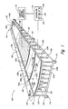
- Figure 1 is a partially schematic isometric view of a wing skin tool assembly configured in accordance with an embodiment of the invention.
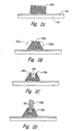
- Figures 2A-2D are a series of enlarged, cross-sectional views illustrating various stages of a method for joining a wing rib to a wing skin in accordance with an embodiment of the invention.
- Figures 3A and 3B are enlarged, cross-sectional views illustrating various stages of a method for joining a wing spar to a wing skin in accordance with an embodiment of the invention.
- Figure 4 is an isometric view of a portion of a wing box assembly configured in accordance with an embodiment of the invention.
- the following disclosure describes methods and systems for manufacturing a family of aircraft wings based on an original wing model.
- the wings can be used for a family of different aircraft, such as a family of jet transport aircraft.
- the wings can vary in a number of different dimensional aspects, including wing area, wing span, airfoil shape, twist, etc. Certain details are set forth in the following description to provide a thorough understanding of various embodiments of the invention. Other details describing well-known structures and systems often associated with aircraft and aircraft wings are not set forth below, however, to avoid unnecessarily obscuring the description of the various embodiments of the invention.
- FIG 1 is a partially schematic isometric view of a wing skin tool assembly 100 (“tool assembly 100") configured in accordance with an embodiment of the invention.
- the tool assembly 100 can include a tool plate 120 having a tool surface 122 that forms an outer mold line (OML) of a composite skin 140.
- the tool plate 120 can be formed from nickel steel alloy (Invar) or other suitable material known in the art.
- the tool surface 122 forms the OML of a wing spar box lower skin.
- the tool surface 122 has the constant-taper or trapezoidal planform of the wing spar box of the biggest wing in a family of wings.
- the tool surface 122 can have other shapes for forming other skins and/or other panels for aircraft and other structures.
- a second tool assembly (not shown) that is at least generally similar in structure and function to the tool assembly 100 can be used to form the corresponding upper skin of the wing spar box.
- the tool plate 120 of the illustrated embodiment is supported by a movable support system 126.
- the movable support system 126 includes a plurality of telescoping actuators 124 (identified individually as actuators 124a-/) which extend upwardly from a base structure 110.
- Each of the actuators 124 is operably coupled to the tool plate 120, and can extend and retract in response to signals from a controller 130 (shown schematically in Figure 1) to change the curvature of the tool surface 122 as desired.
- the controller 130 can include a processor 132 that transmits signals to the actuators 124 in accordance with computer-readable instructions stored on a memory 134.
- the computer-readable instructions can include one or more programs corresponding to different wing skin configurations for a family of aircraft wings.
- the controller 130 can further include a user interface 136 (e.g., keyboard, key pad, pointing device, etc.) for receiving a particular wing skin program selection from a user.
- the composite skin 140 can be manufactured with the tool assembly 100 in one embodiment as follows.
- a user operates the user-interface 136 on the controller 130 to select a desired wing skin configuration.
- the user may select a wing skin configuration corresponding to the largest wing in a particular family of wings.
- the processor 132 responds to this selection by transmitting a corresponding set of signals to the actuators 124 in accordance with a program stored on the memory 134.
- the actuators 124 respond to the signals by individually extending and/or retracting as needed to move the tool surface 122 into the shape associated with the particular wing selection. More specifically, the actuators 124 extend or retract as needed to provide the tool surface 122 with the correct camber, twist, angle, etc. for the particular wing selection.
- an automated tape-laying machine 170 applies fiber-reinforced resin material to the tool surface 122 to form the composite skin 140.
- the fiber-reinforced resin material can include graphite/epoxy and/or other composite materials commonly used in the manufacture of structural components, including, for example, glass, carbon, and/or aramid fibers carried in a polymer matrix of epoxy, vinylester, or polyester thermosetting plastic.
- the tape-laying machine 170 applies the fiber-reinforced resin material in a predetermined number of layers, and in a predetermined pattern and orientation that corresponds to the particular type of wing skin selected by the user. In other embodiments, however, the tape-laying machine 170 can be omitted and the composite material can be applied to the tool surface 122 by hand.
- fiber-reinforced resin material of the composite skin 140 has been applied to the tool surface 122
- additional portions of fiber-reinforced resin material e.g., composite tape
- rib built-up areas 150 identified individually as rib built-up areas 150a- i
- additional fiber-reinforced resin material can be applied to the composite skin 140 along a front spar built-up area 152 and a rear spar built-up area 154.
- the composite lay-up can be evacuated and compressed under a suitable vacuum bag system (not shown) for curing.
- the base structure 110 can include a plurality of rollers 112 so that the ply lay-up can be easily rolled into an oven, autoclave, or other suitable curing station.
- the rear spar built-up area 154, the front spar built-up area 152, and the rib built-up areas 150 can be machined or otherwise finished to facilitate attachment of a rear spar 160, a front spar 158, and a plurality of ribs 156a- i (shown in phantom in Figure 1), to the wing skin 140.
- the actuators 124 can be hydraulically actuated.
- the actuators 124 can be pneumatically actuated.
- the actuators 124 can be mechanically and/or electrically actuated.
- the actuators 124 can include position sensors (not shown) to measure extension/retraction lengths.
- the actuators 124 can further include ball-joints (not shown) for attachment to the tool plate 120. Such joints can allow rotation of the tool plate 120 to accommodate movement of the tool surface 122.
- the movable support system 126 can utilize other shape-changing devices to alter the shape of the tool surface 122.
- Such devices can include, for example, mechanical drive-screws, scissor jacks, pneumatic bladder systems, electromagnetic actuators, servomotors, rack and pinion systems, etc.
- fiber-reinforced resin material can be applied to the entire tool surface 122 from a root portion 146 to a tip portion 144 when producing a skin for the largest wing box of a particular family.
- the fiber-reinforced resin material need only be applied to that portion of the tool surface 122 corresponding to the smaller wing box.
- a smaller wing skin can be produced by applying fiber-reinforced resin material to only that portion of the tool surface 122 that extends from a first chord line 141 to the tip portion 144.
- a smaller wing skin can be produced by applying fiber-reinforced resin material to only that portion of the tool surface 122 that extends from the root portion 146 to a second chord line 142.
- the movable support system 126 can be automatically activated by the controller 130 to change the shape (e.g., the camber, twist, angle, etc.) of the tool surface 122 to accommodate the particular type of wing being built. For example, when a larger wing is being built, the controller 130 can cause the actuators 124 to extend and/or retract as necessary to give the tool surface 122 a desirable shape that provides the resulting wing with favorable aerodynamic characteristics (e.g., low drag). When a smaller wing is being produced, the controller 130 can optimize the shape of the tool surface 122 for the smaller wing. For example, the smaller wing may require less twist than the larger wing.
- the shape e.g., the camber, twist, angle, etc.
- controller 130 can also be programmed to alter the tooling surface 122 for reasons other than aerodynamics including, for example, structural, dynamic, and/or fuel load considerations. Accordingly, a further advantage of the tool assembly 100 is that it can be used to make a series of wing skins having the same, or nearly the same, planform but with different cambers, twists, and/or other dimensional characteristics.
- the actuators 124 can be "passive" devices which are extended and/or retracted by, for example, the composite material applicator 170 to move the tool surface 122 into the pre-programmed shape.
- the material applicator 170 can include a head (not shown) that realeasably attaches to selected actuators and extends or retracts the actuators as needed to provide the tool surface with the desired contour. Once in position, the actuators can self-clamp to maintain the shape of the tool surface 122.
- Figures 2A-2D are a series of enlarged, cross-sectional views taken along line 2A-2A in Figure 1. These views illustrate various stages in a method of forming a self-jigging rib foundation 260 (Figure 2C) in each of the rib built-up areas 150 shown in Figure 1.
- Figure 2C this view illustrates the rib built-up area 150b after bonding to the composite skin 140 during the co-curing process.
- a first side portion 262a and a second side portion 262b of the built-up area 150b can be removed after curing (by, e.g., a computer numerically-controlled (CNC) milling machine) to give the built-up area 150b a tapered cross section.
- CNC computer numerically-controlled
- the rib foundation 260 can have other cross-sectional shapes depending on various structural and/or cost considerations.
- a slot or groove 264 is machined or otherwise formed in the built-up area 150b as shown in Figure 2C.
- a lower portion of the wing rib 156b can then be inserted into the groove 264 and bonded to the rib foundation 260 during assembly of the wing box structure.
- Figures 3A and 3B are enlarged, cross-sectional views taken along line 3A-3A in Figure 1. These views illustrate various stages in a method of forming a self-jigging spar foundation 360 (Figure 3B) in the front spar built-up area 152 of Figure 1.
- the method is at least generally similar to the method described above for forming the wing rib foundations 260.
- Figure 3A shows the front spar built-up area 152 after bonding to the wing skin 140 during the co-curing process.
- a first side portion 362a and a second side portion 362b can be removed from the front spar built-up area 152 to give the spar foundation 360 a tapered cross-section.
- a slot or spar groove 364 can then be machined or otherwise formed in the front spar built-up area 152 to receive a lower edge of the front spar 158.
- controller 130 can control the apparatuses that lay down the composite material and/or form the slots in the built-up areas, in addition to controlling the actuators 124.
- the system that controls the application of the fiber-reinforced resin material can be programmed to address any desired geometry change resulting from a change in wing size.
- different software programs can be used to vary the ply lay-ups in different locations as required to address different load cases. In the foregoing manner, shifting from one size of wing to another, or from one aircraft model to another, only entails implementing new software programs stored on the memory 134 of the controller 130.
- Figure 4 is an exploded isometric view of a root portion of a wing box structure 480 configured in accordance with an embodiment of the invention.
- the front spar 158, the rear spar 160, and the wing ribs 156 are properly located and bonded to the lower wing skin 140 by means of the spar foundation 360 and rib foundation 260 described above.
- An upper wing skin 440 that is at least generally similar in structure and function to the lower wing skin 140 can be located and bonded to the front spar 158, the rear spar 160, and the wing ribs 156 in a similar manner to complete the wing box structure 480.
- rib and spar foundations described above can be used as self-jigging structures to automatically locate ribs and spars, respectively, during wing box construction. This feature can greatly reduce wing manufacturing time. Further, in one embodiment the rib and/or spar locations can remain constant for one or more wings in a given family of wings. Utilizing common rib and spar locations can greatly reduce the number of different parts that are required for the family of wings.
- the same basic tooling could be used for the spar box skins and foundations, but the program implemented by the controller 130 ( Figure 1) could be altered for the particular model to reflect new rib locations and other changes.
- the build process would make no distinction for new rib positions, and no new tooling would be needed.
- another method would be to place ribs at every anticipated location for each wing in the family of wings, and to adjust the strength of each rib to fit the loads for the particular model under construction. In this manner, a typical rib for a smaller wing in the family might become an engine rib for a larger wing in the family.
- a landing gear rib for a smaller wing may become a typical rib for a larger wing member. Tailoring the strength of each rib in each particular case can ensure that the total weight for each wing is at least approximately optimized.
- the tool assembly 100 can be used to form lower wing box skins, and a similar tool can be used to form the corresponding upper wing box skins.
- the tool assemblies can be sized for the largest anticipated wings of a particular family. Smaller wings could then be built by laying down fiber-reinforced resin material (i.e., composite material) over limited areas of the basic tools.
- the largest wing and fuselage combination for the heaviest aircraft in a family of aircraft can be designed first, and the smaller variants derived from this large baseline.
- This approach can ensure that adequate volume provisions exist in the fuselage and/or wings for fuel and other accommodations. Starting with the largest wing member of the family and ensuring it has adequate fuel volume can help ensure that each smaller family member also has adequate fuel volume.
- the landing gear location relative to the wing may have to change. Both inboard and outboard positional changes, as well as fore and aft changes, are likely and could cause the loads in particular ribs to differ from model to model.
- gear ribs for a particular model could designed for particular load requirements.
- generic ribs could be placed at all anticipated gear rib locations for all family members, but the thickness and other structural features could be made unique for the particular load requirements. The same approach can be used for accommodating various engine sizes and location on the wing.
Landscapes
- Engineering & Computer Science (AREA)
- Mechanical Engineering (AREA)
- Aviation & Aerospace Engineering (AREA)
- Manufacturing & Machinery (AREA)
- Chemical & Material Sciences (AREA)
- Composite Materials (AREA)
- Transportation (AREA)
- Moulding By Coating Moulds (AREA)
- Casting Or Compression Moulding Of Plastics Or The Like (AREA)
Priority Applications (1)
| Application Number | Priority Date | Filing Date | Title |
|---|---|---|---|
| EP08001329.5A EP2017051B2 (fr) | 2005-11-01 | 2006-10-27 | Procédé pour fabriquer une série d'ailes d'avion |
Applications Claiming Priority (1)
| Application Number | Priority Date | Filing Date | Title |
|---|---|---|---|
| US11/264,608 US7398586B2 (en) | 2005-11-01 | 2005-11-01 | Methods and systems for manufacturing a family of aircraft wings and other composite structures |
Related Child Applications (3)
| Application Number | Title | Priority Date | Filing Date |
|---|---|---|---|
| EP08001329.5A Division EP2017051B2 (fr) | 2005-11-01 | 2006-10-27 | Procédé pour fabriquer une série d'ailes d'avion |
| EP08001329.5A Previously-Filed-Application EP2017051B2 (fr) | 2005-11-01 | 2006-10-27 | Procédé pour fabriquer une série d'ailes d'avion |
| EP08001329.5A Division-Into EP2017051B2 (fr) | 2005-11-01 | 2006-10-27 | Procédé pour fabriquer une série d'ailes d'avion |
Publications (3)
| Publication Number | Publication Date |
|---|---|
| EP1780120A2 true EP1780120A2 (fr) | 2007-05-02 |
| EP1780120A3 EP1780120A3 (fr) | 2007-07-18 |
| EP1780120B1 EP1780120B1 (fr) | 2016-09-07 |
Family
ID=37726161
Family Applications (2)
| Application Number | Title | Priority Date | Filing Date |
|---|---|---|---|
| EP06022491.2A Active EP1780120B1 (fr) | 2005-11-01 | 2006-10-27 | Outillages de fabrication d'une serie d'ailes d'avions |
| EP08001329.5A Active EP2017051B2 (fr) | 2005-11-01 | 2006-10-27 | Procédé pour fabriquer une série d'ailes d'avion |
Family Applications After (1)
| Application Number | Title | Priority Date | Filing Date |
|---|---|---|---|
| EP08001329.5A Active EP2017051B2 (fr) | 2005-11-01 | 2006-10-27 | Procédé pour fabriquer une série d'ailes d'avion |
Country Status (7)
| Country | Link |
|---|---|
| US (2) | US7398586B2 (fr) |
| EP (2) | EP1780120B1 (fr) |
| JP (1) | JP5207616B2 (fr) |
| KR (1) | KR20070047227A (fr) |
| CN (1) | CN1982040B (fr) |
| AT (1) | ATE555011T1 (fr) |
| ES (2) | ES2386655T5 (fr) |
Cited By (19)
| Publication number | Priority date | Publication date | Assignee | Title |
|---|---|---|---|---|
| WO2011009462A1 (fr) * | 2009-07-23 | 2011-01-27 | Vestas Wind Systems A/S | Procédé de fabrication dun moule pour une pale de rotor déolienne |
| GB2473100A (en) * | 2009-08-31 | 2011-03-02 | Boeing Co | Carrier for moving aircraft structures |
| EP2316629A1 (fr) * | 2009-10-27 | 2011-05-04 | Lm Glasfiber A/S | Système de moule modulaire pour la fabrication d'une partie de coque |
| EP2402253A1 (fr) * | 2009-02-27 | 2012-01-04 | Mitsubishi Heavy Industries, Ltd. | Dispositif de fabrication d'une structure d'aéronef |
| GB2487050A (en) * | 2011-01-04 | 2012-07-11 | Vestas Wind Sys As | Automated techniques for manufacturing fibrous panels |
| ES2387857A1 (es) * | 2010-11-30 | 2012-10-02 | Gamesa Innovation & Technology S.L. | Dispositivo de regulación de las deformaciones del lecho de un molde de geometría aerodinámica y método de moldeo con dicho dispositivo |
| DE102011007487A1 (de) * | 2011-04-15 | 2012-10-18 | Bayerische Motoren Werke Aktiengesellschaft | Aufnahmevorrichtung für Faserhalbzeuge und Verfahren zum Herstellen von faserverstärkten Bauteilen |
| US8333864B2 (en) | 2008-09-30 | 2012-12-18 | The Boeing Company | Compaction of prepreg plies on composite laminate structures |
| US8505361B2 (en) | 2006-12-22 | 2013-08-13 | The Boeing Company | Leak detection in vacuum bags |
| US8568551B2 (en) * | 2007-05-22 | 2013-10-29 | The Boeing Company | Pre-patterned layup kit and method of manufacture |
| WO2012093136A3 (fr) * | 2011-01-05 | 2013-12-05 | Lm Wp Patent Holding A/S | Moule et procédé de fabrication de parties coques |
| US8707766B2 (en) | 2010-04-21 | 2014-04-29 | The Boeing Company | Leak detection in vacuum bags |
| US8752293B2 (en) | 2007-12-07 | 2014-06-17 | The Boeing Company | Method of fabricating structures using composite modules and structures made thereby |
| US8916010B2 (en) | 2007-12-07 | 2014-12-23 | The Boeing Company | Composite manufacturing method |
| US8936695B2 (en) | 2007-07-28 | 2015-01-20 | The Boeing Company | Method for forming and applying composite layups having complex geometries |
| EP2500263A3 (fr) * | 2011-03-17 | 2015-11-04 | United Technologies Corporation | Meilleure rétention de couverture de pale de ventilateur creuse |
| US9770871B2 (en) | 2007-05-22 | 2017-09-26 | The Boeing Company | Method and apparatus for layup placement |
| EP3287373A1 (fr) * | 2016-08-26 | 2018-02-28 | The Boeing Company | Ensemble outil obtenu par la fabrication additive |
| EP3715080A1 (fr) * | 2019-03-26 | 2020-09-30 | Siemens Gamesa Renewable Energy A/S | Dispositif de moulage modulaire, système de moulage et procédé de création d'un moule pour un segment de lame d'une pale d'éolienne |
Families Citing this family (73)
| Publication number | Priority date | Publication date | Assignee | Title |
|---|---|---|---|---|
| US9586699B1 (en) | 1999-08-16 | 2017-03-07 | Smart Drilling And Completion, Inc. | Methods and apparatus for monitoring and fixing holes in composite aircraft |
| US9625361B1 (en) | 2001-08-19 | 2017-04-18 | Smart Drilling And Completion, Inc. | Methods and apparatus to prevent failures of fiber-reinforced composite materials under compressive stresses caused by fluids and gases invading microfractures in the materials |
| GB2409443A (en) * | 2003-12-23 | 2005-06-29 | Airbus Uk Ltd | Rib for an aircraft and the manufacture thereof |
| US7398586B2 (en) * | 2005-11-01 | 2008-07-15 | The Boeing Company | Methods and systems for manufacturing a family of aircraft wings and other composite structures |
| FI118761B (fi) * | 2006-02-09 | 2008-03-14 | Patria Aerostructures Oy | Ilma-aluksen siipi, kiinnitysjärjestely sekä välituki |
| JP4327839B2 (ja) * | 2006-12-13 | 2009-09-09 | 本田技研工業株式会社 | アルミニウム合金製主翼の組立方法 |
| US7777165B2 (en) | 2007-02-02 | 2010-08-17 | Raytheon Company | Methods and apparatus for adjustable surfaces |
| GB0712549D0 (en) * | 2007-06-29 | 2007-08-08 | Airbus Uk Ltd | Improvements in elongate composite structural members |
| WO2009068106A1 (fr) * | 2007-11-29 | 2009-06-04 | Airbus Deutschland Gmbh | Système de positionnement et de montage d'aile |
| EP2234876B1 (fr) * | 2008-01-31 | 2016-05-25 | Raytheon Company | Procédés et appareil pour surfaces ajustables |
| US8016249B2 (en) * | 2008-05-14 | 2011-09-13 | Raytheon Company | Shape-changing structure member with embedded spring |
| US7939178B2 (en) * | 2008-05-14 | 2011-05-10 | Raytheon Company | Shape-changing structure with superelastic foam material |
| US8382042B2 (en) * | 2008-05-14 | 2013-02-26 | Raytheon Company | Structure with reconfigurable polymer material |
| DE102008029058A1 (de) * | 2008-06-18 | 2009-12-24 | GKN Aerospace Services Limited, East Cowes | Verfahren und Formwerkzeug zur Herstellung von Bauteilen aus faserverstärktem Verbundwerkstoff mit Mikrowellen |
| GB0813584D0 (en) * | 2008-07-25 | 2008-09-03 | Airbus Uk Ltd | Method of stiffening a rib |
| US20100148011A1 (en) * | 2008-11-12 | 2010-06-17 | Sanderson Terry M | Telescoping structure and method |
| US8262032B2 (en) * | 2008-11-13 | 2012-09-11 | Raytheon Company | Collapsible wing beams and method |
| US8056853B2 (en) * | 2008-11-25 | 2011-11-15 | Raytheon Company | Reconfigurable wing and method of use |
| US8387536B2 (en) | 2008-12-04 | 2013-03-05 | Raytheon Company | Interceptor vehicle with extendible arms |
| US8573535B2 (en) * | 2009-03-27 | 2013-11-05 | Raytheon Company | Shape-change material and method |
| PL2260994T3 (pl) * | 2009-06-08 | 2013-10-31 | Fibercore Ip Bv | System formy i sposób użycia systemu formy |
| EP2501532A4 (fr) * | 2009-11-17 | 2016-03-16 | Saab Ab | Outil de structure composite |
| CN104010784B (zh) * | 2011-10-19 | 2016-02-24 | 维斯塔斯风力系统有限公司 | 用于将风轮机叶片模具夹持于支承结构的支架 |
| WO2013066439A1 (fr) | 2011-11-04 | 2013-05-10 | Raytheon Company | Ailes de véhicules aériens à extension de corde |
| US9180956B1 (en) | 2012-04-11 | 2015-11-10 | The Boeing Company | Methods and apparatus for attaching an aircraft wing assembly to an aircraft body |
| ES2584557T3 (es) * | 2012-08-16 | 2016-09-28 | Airbus Operations S.L. | Estructura interna altamente integrada de un cajón de torsión de una superficie sustentadora de una aeronave y método para su producción |
| US10118686B2 (en) * | 2012-09-27 | 2018-11-06 | The Boeing Company | Wing root insert system for an aircraft family |
| CN102896482A (zh) * | 2012-10-12 | 2013-01-30 | 黑龙江建龙钢铁有限公司 | 用于冷床摇杆铜瓦更换的装置 |
| US8857765B2 (en) * | 2012-10-16 | 2014-10-14 | The Boeing Company | Method and apparatus for attaching an aircraft fuselage frame to a wing box |
| GB201220937D0 (en) * | 2012-11-21 | 2013-01-02 | Airbus Uk Ltd | Modular structural assembly |
| US9527575B2 (en) * | 2012-11-26 | 2016-12-27 | The Boeing Company | Multi-box wing spar and skin |
| CN105121138B (zh) * | 2013-02-08 | 2018-04-24 | Lm Wp 专利控股有限公司 | 用于制造物品的系统和方法 |
| JP6104730B2 (ja) | 2013-06-18 | 2017-03-29 | 三菱重工業株式会社 | 成形金型及び複合材の成形方法 |
| ES2674659T3 (es) * | 2013-09-23 | 2018-07-03 | Airbus Operations S.L. | Método para fabricar una caja de torsión aeronáutica, caja de torsión y herramienta para fabricar una caja de torsión aeronáutica |
| US10017277B2 (en) * | 2014-04-30 | 2018-07-10 | The Boeing Company | Apparatus, system, and method for supporting a wing assembly |
| US10427254B2 (en) * | 2014-04-30 | 2019-10-01 | The Boeing Company | Flexible manufacturing for aircraft structures |
| US10525524B2 (en) * | 2014-07-09 | 2020-01-07 | The Boeing Company | Dual-interface coupler |
| US10040537B2 (en) * | 2015-01-15 | 2018-08-07 | The Boeing Company | Laminate composite wing structures |
| JP6523693B2 (ja) * | 2015-01-28 | 2019-06-05 | 三菱重工業株式会社 | 航空機部品位置決め装置、航空機組立システム及び航空機組立方法 |
| GB2535497B (en) | 2015-02-18 | 2021-05-05 | Avic Beijing Aeronautical Mfg | A die mechanism, an apparatus, and a method for shaping a component for creep-age forming |
| CN104807627B (zh) * | 2015-05-05 | 2017-05-17 | 中国飞机强度研究所 | 一种中央翼试验支持装置 |
| US9963978B2 (en) * | 2015-06-09 | 2018-05-08 | Ebert Composites Corporation | 3D thermoplastic composite pultrusion system and method |
| CN105291446B (zh) * | 2015-09-11 | 2017-12-08 | 中材科技股份有限公司 | 一种控制复杂曲面缝合织物层密度及均匀性的多点加压装置 |
| CN105415714B (zh) * | 2015-11-25 | 2018-04-03 | 北京金风科创风电设备有限公司 | 合模控制装置 |
| JP6650147B2 (ja) * | 2016-02-02 | 2020-02-19 | 三菱重工業株式会社 | 航空機パネル製造方法及び航空機パネル製造システム |
| CN106312459B (zh) * | 2016-09-27 | 2018-10-12 | 晋西工业集团有限责任公司 | 一种铝制异形长薄板的加工工艺 |
| US10435178B2 (en) | 2016-09-30 | 2019-10-08 | Sikorsky Aircraft Corporation | Machine holding fixture for machining composite laminates on a rotor blade |
| US10723484B2 (en) * | 2016-11-30 | 2020-07-28 | The Boeing Company | Automated fastening machine using a compound contour vacuum track for automation of final assembly from the interior of a fuselage |
| US10710747B2 (en) | 2016-11-30 | 2020-07-14 | The Boeing Company | Compound contour vacuum track for automation of final assembly from the interior of a fuselage |
| CA2987622A1 (fr) * | 2016-12-02 | 2018-06-02 | Stephen Gleason | Composition et methode de formage d'un materiau a ame composite |
| US10830206B2 (en) | 2017-02-03 | 2020-11-10 | General Electric Company | Methods for manufacturing wind turbine rotor blades and components thereof |
| US11098691B2 (en) | 2017-02-03 | 2021-08-24 | General Electric Company | Methods for manufacturing wind turbine rotor blades and components thereof |
| US10906157B2 (en) | 2017-02-20 | 2021-02-02 | The Boeing Company | Modular tooling fixture with interchangeable panel defining a tooling surface |
| US10773464B2 (en) | 2017-11-21 | 2020-09-15 | General Electric Company | Method for manufacturing composite airfoils |
| US11390013B2 (en) | 2017-11-21 | 2022-07-19 | General Electric Company | Vacuum forming mold assembly and associated methods |
| US11668275B2 (en) | 2017-11-21 | 2023-06-06 | General Electric Company | Methods for manufacturing an outer skin of a rotor blade |
| US10920745B2 (en) | 2017-11-21 | 2021-02-16 | General Electric Company | Wind turbine rotor blade components and methods of manufacturing the same |
| US11040503B2 (en) | 2017-11-21 | 2021-06-22 | General Electric Company | Apparatus for manufacturing composite airfoils |
| US11248582B2 (en) * | 2017-11-21 | 2022-02-15 | General Electric Company | Multiple material combinations for printed reinforcement structures of rotor blades |
| US10821652B2 (en) | 2017-11-21 | 2020-11-03 | General Electric Company | Vacuum forming mold assembly and method for creating a vacuum forming mold assembly |
| US10913216B2 (en) | 2017-11-21 | 2021-02-09 | General Electric Company | Methods for manufacturing wind turbine rotor blade panels having printed grid structures |
| US10865769B2 (en) | 2017-11-21 | 2020-12-15 | General Electric Company | Methods for manufacturing wind turbine rotor blade panels having printed grid structures |
| US11035339B2 (en) | 2018-03-26 | 2021-06-15 | General Electric Company | Shear web assembly interconnected with additive manufactured components |
| US10821696B2 (en) | 2018-03-26 | 2020-11-03 | General Electric Company | Methods for manufacturing flatback airfoils for wind turbine rotor blades |
| IT201800010328A1 (it) * | 2018-11-14 | 2020-05-14 | Leonardo Spa | Procedimento per la fabbricazione di un cassone multi-centina in materiale composito con pannelli irrigiditi integrati |
| CN109583114B (zh) * | 2018-12-07 | 2022-11-01 | 江西洪都航空工业集团有限责任公司 | 一种飞机复杂型面拟合及固化方法 |
| CN110065650B (zh) * | 2019-05-24 | 2024-03-12 | 凌云(宜昌)航空装备工程有限公司 | 电动升降式飞机机头修理工作平台 |
| CN114206722A (zh) * | 2019-06-20 | 2022-03-18 | 银河有限责任公司 | 集成拉挤成型复合型材及用于制造其的方法 |
| US11352124B2 (en) * | 2019-11-01 | 2022-06-07 | The Boeing Company | Continuous skin leading edge slats |
| CN114055812A (zh) * | 2020-07-29 | 2022-02-18 | 中国航发商用航空发动机有限责任公司 | 纤维织物卷绕变形的控制方法及其成型模具 |
| US11801619B2 (en) * | 2021-10-05 | 2023-10-31 | The Boeing Company | Rapid tooling layup mandrel |
| CN113977983B (zh) * | 2021-10-15 | 2023-06-30 | 江西洪都航空工业集团有限责任公司 | 一种复合材料壁板结构件的筋条定位装置及方法 |
| CN115556052A (zh) * | 2022-11-10 | 2023-01-03 | 航宇智造(北京)工程技术有限公司 | 一种可应用于大型蒙皮agv多工位托架 |
Citations (2)
| Publication number | Priority date | Publication date | Assignee | Title |
|---|---|---|---|---|
| WO1987007233A1 (fr) | 1986-05-21 | 1987-12-03 | Goldspar Australia Pty. Limited | Procede et appareil pour former des voiles |
| US5851563A (en) | 1997-03-28 | 1998-12-22 | Mcdonnell Douglas Corporation | Reconfigure modular tooling |
Family Cites Families (57)
| Publication number | Priority date | Publication date | Assignee | Title |
|---|---|---|---|---|
| DE634884C (de) | 1936-09-05 | Hamburger Flugzeugbau G M B H | Aus etwa halbkreisfoermigen Schalen bestehender Tragholm fuer Flugzeuge | |
| US1354677A (en) * | 1918-04-08 | 1920-10-05 | Melville W Mix | Knockdown airplane-fuselage and process therefor |
| US1865964A (en) * | 1926-09-27 | 1932-07-05 | Rohrbach Patents Corp | Monoplane |
| US2001260A (en) * | 1932-07-20 | 1935-05-14 | Martin James | Construction and arrangement of aeroplane wings |
| US2370801A (en) * | 1941-05-14 | 1945-03-06 | Cons Vultee Aireraft Corp | Airplane wing structure |
| US2412778A (en) * | 1944-12-18 | 1946-12-17 | Cons Vultee Aircraft Corp | Suspension type flooring for aircraft |
| US2779558A (en) * | 1952-04-09 | 1957-01-29 | Sncase | Fuselage of aerodynes |
| US2750134A (en) * | 1952-04-17 | 1956-06-12 | Lockheed Aircraft Corp | Multiple wheel main landing gear |
| US2807437A (en) * | 1952-05-01 | 1957-09-24 | Thompson Prod Inc | Method for making intricate hollow powder metal parts |
| US2749061A (en) * | 1954-06-18 | 1956-06-05 | Wesley A Franz | Airplane wing stress compensating structure assembly |
| US3018985A (en) * | 1956-12-31 | 1962-01-30 | Martin Marietta Corp | Swept wing with unswept spar |
| DE1952279B2 (de) | 1969-10-17 | 1974-02-07 | Dornier Gmbh, 7990 Friedrichshafen | Vorrichtung zum Herstellen einer gewölbten Sandwichplatte |
| GB1425312A (en) | 1972-01-31 | 1976-02-18 | Flint M F Goater P J | Adjustable moulds |
| US4417708A (en) * | 1982-05-12 | 1983-11-29 | Grumman Aerospace Corporation | Interchangeable wing aircraft |
| DE3242949A1 (de) | 1982-11-20 | 1984-05-24 | Messerschmitt-Bölkow-Blohm GmbH, 8000 München | Verfahren zur positionierung von lagenzuschnitten aus faserverstaerkten werkstoffen (fvw) |
| FR2548577B1 (fr) | 1983-07-04 | 1986-04-18 | Hurel Dubois Avions | Procede de constitution d'une matrice adaptable, permettant de donner a un produit mince une configuration quelconque, et matrice realisee selon ce procede |
| JPS6050065A (ja) * | 1983-08-30 | 1985-03-19 | 川崎重工業株式会社 | 板材と骨材からなる構造物の組立装置とその組立方法 |
| IL77125A0 (en) † | 1984-11-23 | 1986-04-29 | Fox Brothers Ltd | Graduated aircraft design and construction method |
| GB8508419D0 (en) * | 1985-04-01 | 1985-05-09 | Short Brothers Ltd | Moulding fibre reinforced resin |
| US4731144A (en) * | 1986-07-14 | 1988-03-15 | Harris Corporation | Method of shaping an antenna panel |
| FR2614264B1 (fr) * | 1987-04-24 | 1989-07-21 | Aerospatiale | Systeme de roulement pour aeronef. |
| US4894903A (en) * | 1988-07-06 | 1990-01-23 | The Boeing Company | Assembly jig and method for making wing panels |
| US5039032A (en) * | 1988-11-07 | 1991-08-13 | The Boeing Company | High taper wing tip extension |
| US5097784A (en) * | 1990-08-21 | 1992-03-24 | North Sails Group, Inc. | Sail of one piece three dimensional laminated fabric having uninterrupted load bearing yarns |
| GB9024387D0 (en) * | 1990-11-09 | 1991-01-02 | British Aerospace | Carbon fibre composite wing manufacture |
| US5275358A (en) * | 1991-08-02 | 1994-01-04 | The Boeing Company | Wing/winglet configurations and methods for aircraft |
| US5273806A (en) * | 1991-10-03 | 1993-12-28 | Lockshaw James J | Structural element with interlocking ribbing |
| AT398064B (de) | 1992-07-01 | 1994-09-26 | Hoac Austria Flugzeugwerk Wr N | Kunststoff-verbundprofil, insbesondere flügelholm für den flugzeugbau |
| GB2268699B (en) | 1992-07-16 | 1996-09-18 | British Aerospace | Forming fibre reinforced plastics laminates |
| JPH06255587A (ja) * | 1993-03-09 | 1994-09-13 | Honda Motor Co Ltd | 航空機 |
| CN1056800C (zh) * | 1994-12-20 | 2000-09-27 | 波音公司 | 手动辅助操作层压系统 |
| JPH08216159A (ja) * | 1995-02-14 | 1996-08-27 | Hitachi Chem Co Ltd | Frp成形品用成形型 |
| US5897078A (en) * | 1995-12-15 | 1999-04-27 | The Boeing Company | Multi-service common airframe-based aircraft |
| US5746553A (en) * | 1996-04-08 | 1998-05-05 | The Boeing Company | Dual purpose lay-up tool |
| US5692703A (en) * | 1996-05-10 | 1997-12-02 | Mcdonnell Douglas Corporation | Multiple application wheel well design |
| US5909858A (en) | 1997-06-19 | 1999-06-08 | Mcdonnell Douglas Corporation | Spanwise transition section for blended wing-body aircraft |
| JP4001415B2 (ja) * | 1998-02-02 | 2007-10-31 | 櫻護謨株式会社 | リブ構造体の製造方法 |
| DE19810478B4 (de) | 1998-03-11 | 2004-10-07 | Bayerische Motoren Werke Ag | Verfahren zur Herstellung von dreidimensional verformten Bauteilen |
| WO1999046079A1 (fr) * | 1998-03-12 | 1999-09-16 | General Electro Mechanical Corporation | Systeme et procede de fixation flexible |
| JP2000006893A (ja) * | 1998-06-23 | 2000-01-11 | Fuji Heavy Ind Ltd | 複合材翼構造 |
| US6106649A (en) * | 1998-10-02 | 2000-08-22 | North Sails Group, Inc. | Continuous method of making a three dimensional sail |
| US6513757B1 (en) * | 1999-07-19 | 2003-02-04 | Fuji Jukogyo Kabushiki Kaisha | Wing of composite material and method of fabricating the same |
| AU2002232779A1 (en) * | 2000-10-19 | 2002-05-06 | Fg Products, Inc. | Bulkhead and partition systems |
| US6849150B1 (en) | 2001-01-16 | 2005-02-01 | Lockheed Martin Corporation | System and method of forming structural assemblies with 3-D woven joint pre-forms |
| US6863767B2 (en) * | 2001-08-23 | 2005-03-08 | Lockheed Martin Corporation | Paste-bond clevis joint |
| JP4574086B2 (ja) * | 2001-09-03 | 2010-11-04 | 富士重工業株式会社 | 複合材翼の製造方法および複合材翼 |
| US6649006B2 (en) | 2001-10-09 | 2003-11-18 | Lockheed Martin Corporation | Method of making a waffle stiffener |
| US6726149B2 (en) * | 2002-05-31 | 2004-04-27 | The Boeing Company | Derivative aircraft and methods for their manufacture |
| JP3632176B2 (ja) * | 2002-06-13 | 2005-03-23 | 川崎重工業株式会社 | 航空機用複合材パネルの製造方法及びその装置 |
| US6945727B2 (en) * | 2002-07-19 | 2005-09-20 | The Boeing Company | Apparatuses and methods for joining structural members, such as composite structural members |
| JP4121839B2 (ja) * | 2002-12-03 | 2008-07-23 | 富士重工業株式会社 | 複合材の成形治具 |
| JP2006123220A (ja) * | 2004-10-26 | 2006-05-18 | Matsushita Electric Works Ltd | 大型成形品生産型 |
| US7398586B2 (en) * | 2005-11-01 | 2008-07-15 | The Boeing Company | Methods and systems for manufacturing a family of aircraft wings and other composite structures |
| US7546979B1 (en) * | 2006-09-15 | 2009-06-16 | The Boeing Company | Trapezoidal panel pin joint allowing free deflection between fuselage and wing |
| FR2913400B1 (fr) * | 2007-03-07 | 2009-11-20 | Airbus France | Plancher d'aeronef et fuselage muni d'un tel plancher. |
| FR2915173B1 (fr) * | 2007-04-17 | 2009-10-23 | Airbus Sa Sa | Dispositif de fixation d'un organe de sustentation au fuselage d'un avion. |
| US7887009B2 (en) * | 2007-12-05 | 2011-02-15 | The Boeing Company | Methods and systems for attaching aircraft wings to fuselages |
-
2005
- 2005-11-01 US US11/264,608 patent/US7398586B2/en active Active
-
2006
- 2006-10-27 AT AT08001329T patent/ATE555011T1/de active
- 2006-10-27 EP EP06022491.2A patent/EP1780120B1/fr active Active
- 2006-10-27 ES ES08001329.5T patent/ES2386655T5/es active Active
- 2006-10-27 ES ES06022491.2T patent/ES2606063T3/es active Active
- 2006-10-27 EP EP08001329.5A patent/EP2017051B2/fr active Active
- 2006-10-31 JP JP2006295900A patent/JP5207616B2/ja active Active
- 2006-11-01 KR KR1020060107239A patent/KR20070047227A/ko active Search and Examination
- 2006-11-01 CN CN2006100639203A patent/CN1982040B/zh active Active
-
2008
- 2008-06-10 US US12/136,392 patent/US8146242B2/en active Active
Patent Citations (2)
| Publication number | Priority date | Publication date | Assignee | Title |
|---|---|---|---|---|
| WO1987007233A1 (fr) | 1986-05-21 | 1987-12-03 | Goldspar Australia Pty. Limited | Procede et appareil pour former des voiles |
| US5851563A (en) | 1997-03-28 | 1998-12-22 | Mcdonnell Douglas Corporation | Reconfigure modular tooling |
Cited By (37)
| Publication number | Priority date | Publication date | Assignee | Title |
|---|---|---|---|---|
| US9046437B2 (en) | 2006-12-22 | 2015-06-02 | The Boeing Company | Leak detection in vacuum bags |
| US8505361B2 (en) | 2006-12-22 | 2013-08-13 | The Boeing Company | Leak detection in vacuum bags |
| US9770871B2 (en) | 2007-05-22 | 2017-09-26 | The Boeing Company | Method and apparatus for layup placement |
| US8568551B2 (en) * | 2007-05-22 | 2013-10-29 | The Boeing Company | Pre-patterned layup kit and method of manufacture |
| US10603848B2 (en) | 2007-05-22 | 2020-03-31 | The Boeing Company | Apparatus for layup placement |
| US9500593B2 (en) | 2007-07-28 | 2016-11-22 | The Boeing Company | Leak detection in vacuum bags |
| US10052827B2 (en) | 2007-07-28 | 2018-08-21 | The Boeing Company | Method for forming and applying composite layups having complex geometries |
| US8936695B2 (en) | 2007-07-28 | 2015-01-20 | The Boeing Company | Method for forming and applying composite layups having complex geometries |
| US9764499B2 (en) | 2007-12-07 | 2017-09-19 | The Boeing Company | Structures using composite modules and structures made thereby |
| US8916010B2 (en) | 2007-12-07 | 2014-12-23 | The Boeing Company | Composite manufacturing method |
| US8752293B2 (en) | 2007-12-07 | 2014-06-17 | The Boeing Company | Method of fabricating structures using composite modules and structures made thereby |
| US8333864B2 (en) | 2008-09-30 | 2012-12-18 | The Boeing Company | Compaction of prepreg plies on composite laminate structures |
| US8613301B2 (en) | 2008-09-30 | 2013-12-24 | The Boeing Company | Compaction of prepreg plies on composite laminate structures |
| EP2402253A4 (fr) * | 2009-02-27 | 2014-06-18 | Mitsubishi Heavy Ind Ltd | Dispositif de fabrication d'une structure d'aéronef |
| US8869367B2 (en) | 2009-02-27 | 2014-10-28 | Mitsubishi Heavy Industries, Ltd. | Aircraft structure manufacturing apparatus |
| EP2402253A1 (fr) * | 2009-02-27 | 2012-01-04 | Mitsubishi Heavy Industries, Ltd. | Dispositif de fabrication d'une structure d'aéronef |
| CN102481706A (zh) * | 2009-07-23 | 2012-05-30 | 维斯塔斯风力系统有限公司 | 风轮机转子叶片所用的模具的制造方法 |
| WO2011009462A1 (fr) * | 2009-07-23 | 2011-01-27 | Vestas Wind Systems A/S | Procédé de fabrication dun moule pour une pale de rotor déolienne |
| CN102481706B (zh) * | 2009-07-23 | 2014-07-16 | 维斯塔斯风力系统有限公司 | 风轮机转子叶片所用的模具的制造方法 |
| US8539658B2 (en) | 2009-08-31 | 2013-09-24 | The Boeing Company | Autonomous carrier for continuously moving wing assembly line |
| GB2473100A (en) * | 2009-08-31 | 2011-03-02 | Boeing Co | Carrier for moving aircraft structures |
| GB2473100B (en) * | 2009-08-31 | 2012-03-14 | Boeing Co | Autonomous carrier for continously moving wing assembly line |
| US8951034B2 (en) | 2009-10-27 | 2015-02-10 | Lm Glasfiber A/S | Modular mould system for manufacturing a shell part |
| EP2316629A1 (fr) * | 2009-10-27 | 2011-05-04 | Lm Glasfiber A/S | Système de moule modulaire pour la fabrication d'une partie de coque |
| WO2011051130A1 (fr) * | 2009-10-27 | 2011-05-05 | Lm Glasfiber A/S | Système de moulage modulaire pour la fabrication d'une partie coquille |
| US8707766B2 (en) | 2010-04-21 | 2014-04-29 | The Boeing Company | Leak detection in vacuum bags |
| ES2387857A1 (es) * | 2010-11-30 | 2012-10-02 | Gamesa Innovation & Technology S.L. | Dispositivo de regulación de las deformaciones del lecho de un molde de geometría aerodinámica y método de moldeo con dicho dispositivo |
| GB2487050A (en) * | 2011-01-04 | 2012-07-11 | Vestas Wind Sys As | Automated techniques for manufacturing fibrous panels |
| WO2012093136A3 (fr) * | 2011-01-05 | 2013-12-05 | Lm Wp Patent Holding A/S | Moule et procédé de fabrication de parties coques |
| EP2500263A3 (fr) * | 2011-03-17 | 2015-11-04 | United Technologies Corporation | Meilleure rétention de couverture de pale de ventilateur creuse |
| DE102011007487A1 (de) * | 2011-04-15 | 2012-10-18 | Bayerische Motoren Werke Aktiengesellschaft | Aufnahmevorrichtung für Faserhalbzeuge und Verfahren zum Herstellen von faserverstärkten Bauteilen |
| EP3287373A1 (fr) * | 2016-08-26 | 2018-02-28 | The Boeing Company | Ensemble outil obtenu par la fabrication additive |
| EP3498612A3 (fr) * | 2016-08-26 | 2019-07-24 | The Boeing Company | Ensemble outil obtenu par la fabrication additive |
| US10392131B2 (en) | 2016-08-26 | 2019-08-27 | The Boeing Company | Additive manufactured tool assembly |
| EP3795479A1 (fr) * | 2016-08-26 | 2021-03-24 | The Boeing Company | Outil de support fabriqué de manière additive |
| EP3715080A1 (fr) * | 2019-03-26 | 2020-09-30 | Siemens Gamesa Renewable Energy A/S | Dispositif de moulage modulaire, système de moulage et procédé de création d'un moule pour un segment de lame d'une pale d'éolienne |
| US11820046B2 (en) | 2019-03-26 | 2023-11-21 | Siemens Gamesa Renewable Energy A/S | Modular molding device, molding system and method for creating a mold for a blade segment of a wind turbine blade of a wind turbine |
Also Published As
| Publication number | Publication date |
|---|---|
| US20070107189A1 (en) | 2007-05-17 |
| US20090056109A1 (en) | 2009-03-05 |
| US8146242B2 (en) | 2012-04-03 |
| CN1982040B (zh) | 2011-05-18 |
| JP2007125890A (ja) | 2007-05-24 |
| CN1982040A (zh) | 2007-06-20 |
| EP2017051A3 (fr) | 2011-04-13 |
| ES2606063T3 (es) | 2017-03-17 |
| ES2386655T5 (es) | 2015-12-14 |
| US7398586B2 (en) | 2008-07-15 |
| KR20070047227A (ko) | 2007-05-04 |
| EP2017051B2 (fr) | 2015-08-26 |
| EP1780120A3 (fr) | 2007-07-18 |
| ES2386655T3 (es) | 2012-08-24 |
| JP5207616B2 (ja) | 2013-06-12 |
| ATE555011T1 (de) | 2012-05-15 |
| EP2017051B1 (fr) | 2012-04-25 |
| EP2017051A2 (fr) | 2009-01-21 |
| EP1780120B1 (fr) | 2016-09-07 |
Similar Documents
| Publication | Publication Date | Title |
|---|---|---|
| EP1780120B1 (fr) | Outillages de fabrication d'une serie d'ailes d'avions | |
| EP3683029A2 (fr) | Longerons composites profilés | |
| EP2152574B1 (fr) | Procédé de fabrication de lisses en matériau composite | |
| EP2631062B1 (fr) | Positionnement de fibre automatisé comprenant un outil de mandrinage de superposition | |
| EP2687436B1 (fr) | Bord d'attaque hautement intégré d'une surface de portance d'un aéronef | |
| EP2735504B1 (fr) | Procédé de production d'une structure hautement intégrée comprenant des nervures de bord d'attaque et de fuite d'une surface portante d'un aéronef | |
| EP2905220A1 (fr) | Lisse I-blade stratifiée | |
| EP2789534A1 (fr) | Longeron d'aile à plusieurs carters et revêtement | |
| EP2735502B1 (fr) | Caisson de torsion optimisé pour aéronef | |
| CN108725749B (zh) | 纤维增强复合材料翼型件结构 | |
| EP1899149A1 (fr) | Procédé permettant de produire un composant présentant sensiblement une forme de coque | |
| US9701393B2 (en) | Highly integrated inner structure of a torsion box of an aircraft lifting surface | |
| EP3702142B1 (fr) | Raidisseur composite | |
| US20230063490A1 (en) | Forming apparatus, methods, and systems | |
| Sen et al. | Innovative manufacturing processes for a lightweight, affordable composite helicopter airframe |
Legal Events
| Date | Code | Title | Description |
|---|---|---|---|
| PUAI | Public reference made under article 153(3) epc to a published international application that has entered the european phase |
Free format text: ORIGINAL CODE: 0009012 |
|
| AK | Designated contracting states |
Kind code of ref document: A2 Designated state(s): AT BE BG CH CY CZ DE DK EE ES FI FR GB GR HU IE IS IT LI LT LU LV MC NL PL PT RO SE SI SK TR |
|
| AX | Request for extension of the european patent |
Extension state: AL BA HR MK YU |
|
| PUAL | Search report despatched |
Free format text: ORIGINAL CODE: 0009013 |
|
| AK | Designated contracting states |
Kind code of ref document: A3 Designated state(s): AT BE BG CH CY CZ DE DK EE ES FI FR GB GR HU IE IS IT LI LT LU LV MC NL PL PT RO SE SI SK TR |
|
| AX | Request for extension of the european patent |
Extension state: AL BA HR MK YU |
|
| 17P | Request for examination filed |
Effective date: 20080118 |
|
| AKX | Designation fees paid |
Designated state(s): AT BE BG CH CY CZ DE DK EE ES FI FR GB GR HU IE IS IT LI LT LU LV MC NL PL PT RO SE SI SK TR |
|
| 17Q | First examination report despatched |
Effective date: 20110218 |
|
| GRAP | Despatch of communication of intention to grant a patent |
Free format text: ORIGINAL CODE: EPIDOSNIGR1 |
|
| INTG | Intention to grant announced |
Effective date: 20160428 |
|
| GRAS | Grant fee paid |
Free format text: ORIGINAL CODE: EPIDOSNIGR3 |
|
| GRAA | (expected) grant |
Free format text: ORIGINAL CODE: 0009210 |
|
| AK | Designated contracting states |
Kind code of ref document: B1 Designated state(s): AT BE BG CH CY CZ DE DK EE ES FI FR GB GR HU IE IS IT LI LT LU LV MC NL PL PT RO SE SI SK TR |
|
| REG | Reference to a national code |
Ref country code: GB Ref legal event code: FG4D |
|
| REG | Reference to a national code |
Ref country code: CH Ref legal event code: EP |
|
| REG | Reference to a national code |
Ref country code: IE Ref legal event code: FG4D |
|
| REG | Reference to a national code |
Ref country code: DE Ref legal event code: R096 Ref document number: 602006050178 Country of ref document: DE |
|
| REG | Reference to a national code |
Ref country code: AT Ref legal event code: REF Ref document number: 826580 Country of ref document: AT Kind code of ref document: T Effective date: 20161015 |
|
| REG | Reference to a national code |
Ref country code: FR Ref legal event code: PLFP Year of fee payment: 11 |
|
| REG | Reference to a national code |
Ref country code: LT Ref legal event code: MG4D |
|
| REG | Reference to a national code |
Ref country code: NL Ref legal event code: MP Effective date: 20160907 |
|
| PG25 | Lapsed in a contracting state [announced via postgrant information from national office to epo] |
Ref country code: LT Free format text: LAPSE BECAUSE OF FAILURE TO SUBMIT A TRANSLATION OF THE DESCRIPTION OR TO PAY THE FEE WITHIN THE PRESCRIBED TIME-LIMIT Effective date: 20160907 Ref country code: FI Free format text: LAPSE BECAUSE OF FAILURE TO SUBMIT A TRANSLATION OF THE DESCRIPTION OR TO PAY THE FEE WITHIN THE PRESCRIBED TIME-LIMIT Effective date: 20160907 |
|
| REG | Reference to a national code |
Ref country code: AT Ref legal event code: MK05 Ref document number: 826580 Country of ref document: AT Kind code of ref document: T Effective date: 20160907 |
|
| PG25 | Lapsed in a contracting state [announced via postgrant information from national office to epo] |
Ref country code: GR Free format text: LAPSE BECAUSE OF FAILURE TO SUBMIT A TRANSLATION OF THE DESCRIPTION OR TO PAY THE FEE WITHIN THE PRESCRIBED TIME-LIMIT Effective date: 20161208 Ref country code: SE Free format text: LAPSE BECAUSE OF FAILURE TO SUBMIT A TRANSLATION OF THE DESCRIPTION OR TO PAY THE FEE WITHIN THE PRESCRIBED TIME-LIMIT Effective date: 20160907 Ref country code: LV Free format text: LAPSE BECAUSE OF FAILURE TO SUBMIT A TRANSLATION OF THE DESCRIPTION OR TO PAY THE FEE WITHIN THE PRESCRIBED TIME-LIMIT Effective date: 20160907 Ref country code: NL Free format text: LAPSE BECAUSE OF FAILURE TO SUBMIT A TRANSLATION OF THE DESCRIPTION OR TO PAY THE FEE WITHIN THE PRESCRIBED TIME-LIMIT Effective date: 20160907 Ref country code: BE Free format text: LAPSE BECAUSE OF NON-PAYMENT OF DUE FEES Effective date: 20161031 |
|
| REG | Reference to a national code |
Ref country code: ES Ref legal event code: FG2A Ref document number: 2606063 Country of ref document: ES Kind code of ref document: T3 Effective date: 20170317 |
|
| PG25 | Lapsed in a contracting state [announced via postgrant information from national office to epo] |
Ref country code: EE Free format text: LAPSE BECAUSE OF FAILURE TO SUBMIT A TRANSLATION OF THE DESCRIPTION OR TO PAY THE FEE WITHIN THE PRESCRIBED TIME-LIMIT Effective date: 20160907 Ref country code: RO Free format text: LAPSE BECAUSE OF FAILURE TO SUBMIT A TRANSLATION OF THE DESCRIPTION OR TO PAY THE FEE WITHIN THE PRESCRIBED TIME-LIMIT Effective date: 20160907 |
|
| PG25 | Lapsed in a contracting state [announced via postgrant information from national office to epo] |
Ref country code: IS Free format text: LAPSE BECAUSE OF FAILURE TO SUBMIT A TRANSLATION OF THE DESCRIPTION OR TO PAY THE FEE WITHIN THE PRESCRIBED TIME-LIMIT Effective date: 20170107 Ref country code: PL Free format text: LAPSE BECAUSE OF FAILURE TO SUBMIT A TRANSLATION OF THE DESCRIPTION OR TO PAY THE FEE WITHIN THE PRESCRIBED TIME-LIMIT Effective date: 20160907 Ref country code: PT Free format text: LAPSE BECAUSE OF FAILURE TO SUBMIT A TRANSLATION OF THE DESCRIPTION OR TO PAY THE FEE WITHIN THE PRESCRIBED TIME-LIMIT Effective date: 20170109 Ref country code: SK Free format text: LAPSE BECAUSE OF FAILURE TO SUBMIT A TRANSLATION OF THE DESCRIPTION OR TO PAY THE FEE WITHIN THE PRESCRIBED TIME-LIMIT Effective date: 20160907 Ref country code: BG Free format text: LAPSE BECAUSE OF FAILURE TO SUBMIT A TRANSLATION OF THE DESCRIPTION OR TO PAY THE FEE WITHIN THE PRESCRIBED TIME-LIMIT Effective date: 20161207 Ref country code: AT Free format text: LAPSE BECAUSE OF FAILURE TO SUBMIT A TRANSLATION OF THE DESCRIPTION OR TO PAY THE FEE WITHIN THE PRESCRIBED TIME-LIMIT Effective date: 20160907 Ref country code: CZ Free format text: LAPSE BECAUSE OF FAILURE TO SUBMIT A TRANSLATION OF THE DESCRIPTION OR TO PAY THE FEE WITHIN THE PRESCRIBED TIME-LIMIT Effective date: 20160907 Ref country code: BE Free format text: LAPSE BECAUSE OF FAILURE TO SUBMIT A TRANSLATION OF THE DESCRIPTION OR TO PAY THE FEE WITHIN THE PRESCRIBED TIME-LIMIT Effective date: 20160907 |
|
| REG | Reference to a national code |
Ref country code: CH Ref legal event code: PL |
|
| REG | Reference to a national code |
Ref country code: DE Ref legal event code: R097 Ref document number: 602006050178 Country of ref document: DE |
|
| PLBE | No opposition filed within time limit |
Free format text: ORIGINAL CODE: 0009261 |
|
| STAA | Information on the status of an ep patent application or granted ep patent |
Free format text: STATUS: NO OPPOSITION FILED WITHIN TIME LIMIT |
|
| REG | Reference to a national code |
Ref country code: IE Ref legal event code: MM4A |
|
| PG25 | Lapsed in a contracting state [announced via postgrant information from national office to epo] |
Ref country code: DK Free format text: LAPSE BECAUSE OF FAILURE TO SUBMIT A TRANSLATION OF THE DESCRIPTION OR TO PAY THE FEE WITHIN THE PRESCRIBED TIME-LIMIT Effective date: 20160907 Ref country code: LI Free format text: LAPSE BECAUSE OF NON-PAYMENT OF DUE FEES Effective date: 20161031 Ref country code: CH Free format text: LAPSE BECAUSE OF NON-PAYMENT OF DUE FEES Effective date: 20161031 |
|
| 26N | No opposition filed |
Effective date: 20170608 |
|
| PG25 | Lapsed in a contracting state [announced via postgrant information from national office to epo] |
Ref country code: SI Free format text: LAPSE BECAUSE OF FAILURE TO SUBMIT A TRANSLATION OF THE DESCRIPTION OR TO PAY THE FEE WITHIN THE PRESCRIBED TIME-LIMIT Effective date: 20160907 Ref country code: LU Free format text: LAPSE BECAUSE OF NON-PAYMENT OF DUE FEES Effective date: 20161027 |
|
| REG | Reference to a national code |
Ref country code: FR Ref legal event code: PLFP Year of fee payment: 12 |
|
| PG25 | Lapsed in a contracting state [announced via postgrant information from national office to epo] |
Ref country code: IE Free format text: LAPSE BECAUSE OF NON-PAYMENT OF DUE FEES Effective date: 20161027 |
|
| PG25 | Lapsed in a contracting state [announced via postgrant information from national office to epo] |
Ref country code: CY Free format text: LAPSE BECAUSE OF FAILURE TO SUBMIT A TRANSLATION OF THE DESCRIPTION OR TO PAY THE FEE WITHIN THE PRESCRIBED TIME-LIMIT Effective date: 20160907 Ref country code: HU Free format text: LAPSE BECAUSE OF FAILURE TO SUBMIT A TRANSLATION OF THE DESCRIPTION OR TO PAY THE FEE WITHIN THE PRESCRIBED TIME-LIMIT; INVALID AB INITIO Effective date: 20061027 |
|
| PG25 | Lapsed in a contracting state [announced via postgrant information from national office to epo] |
Ref country code: TR Free format text: LAPSE BECAUSE OF FAILURE TO SUBMIT A TRANSLATION OF THE DESCRIPTION OR TO PAY THE FEE WITHIN THE PRESCRIBED TIME-LIMIT Effective date: 20160907 Ref country code: MC Free format text: LAPSE BECAUSE OF FAILURE TO SUBMIT A TRANSLATION OF THE DESCRIPTION OR TO PAY THE FEE WITHIN THE PRESCRIBED TIME-LIMIT Effective date: 20160907 |
|
| REG | Reference to a national code |
Ref country code: FR Ref legal event code: PLFP Year of fee payment: 13 |
|
| REG | Reference to a national code |
Ref country code: DE Ref legal event code: R082 Ref document number: 602006050178 Country of ref document: DE Representative=s name: MAIER, LL.M., MICHAEL C., DE Ref country code: DE Ref legal event code: R082 Ref document number: 602006050178 Country of ref document: DE Representative=s name: BOULT WADE TENNANT LLP, DE |
|
| REG | Reference to a national code |
Ref country code: DE Ref legal event code: R082 Ref document number: 602006050178 Country of ref document: DE Representative=s name: BOULT WADE TENNANT LLP, DE |
|
| P01 | Opt-out of the competence of the unified patent court (upc) registered |
Effective date: 20230516 |
|
| PGFP | Annual fee paid to national office [announced via postgrant information from national office to epo] |
Ref country code: GB Payment date: 20231027 Year of fee payment: 18 |
|
| PGFP | Annual fee paid to national office [announced via postgrant information from national office to epo] |
Ref country code: ES Payment date: 20231102 Year of fee payment: 18 |
|
| PGFP | Annual fee paid to national office [announced via postgrant information from national office to epo] |
Ref country code: IT Payment date: 20231023 Year of fee payment: 18 Ref country code: FR Payment date: 20231025 Year of fee payment: 18 Ref country code: DE Payment date: 20231027 Year of fee payment: 18 |