EP1780071A2 - Autositz mit einer Vorrichtung zur Neigungs- und Höhenverstellung - Google Patents
Autositz mit einer Vorrichtung zur Neigungs- und Höhenverstellung Download PDFInfo
- Publication number
- EP1780071A2 EP1780071A2 EP06022579A EP06022579A EP1780071A2 EP 1780071 A2 EP1780071 A2 EP 1780071A2 EP 06022579 A EP06022579 A EP 06022579A EP 06022579 A EP06022579 A EP 06022579A EP 1780071 A2 EP1780071 A2 EP 1780071A2
- Authority
- EP
- European Patent Office
- Prior art keywords
- seat
- seat frame
- height
- adjustment device
- adjusting
- Prior art date
- Legal status (The legal status is an assumption and is not a legal conclusion. Google has not performed a legal analysis and makes no representation as to the accuracy of the status listed.)
- Granted
Links
Images

Classifications
-
- B—PERFORMING OPERATIONS; TRANSPORTING
- B60—VEHICLES IN GENERAL
- B60N—SEATS SPECIALLY ADAPTED FOR VEHICLES; VEHICLE PASSENGER ACCOMMODATION NOT OTHERWISE PROVIDED FOR
- B60N2/00—Seats specially adapted for vehicles; Arrangement or mounting of seats in vehicles
- B60N2/02—Seats specially adapted for vehicles; Arrangement or mounting of seats in vehicles the seat or part thereof being movable, e.g. adjustable
- B60N2/04—Seats specially adapted for vehicles; Arrangement or mounting of seats in vehicles the seat or part thereof being movable, e.g. adjustable the whole seat being movable
- B60N2/16—Seats specially adapted for vehicles; Arrangement or mounting of seats in vehicles the seat or part thereof being movable, e.g. adjustable the whole seat being movable height-adjustable
- B60N2/18—Seats specially adapted for vehicles; Arrangement or mounting of seats in vehicles the seat or part thereof being movable, e.g. adjustable the whole seat being movable height-adjustable the front or the rear portion of the seat being adjustable, e.g. independently of each other
- B60N2/185—Seats specially adapted for vehicles; Arrangement or mounting of seats in vehicles the seat or part thereof being movable, e.g. adjustable the whole seat being movable height-adjustable the front or the rear portion of the seat being adjustable, e.g. independently of each other characterised by the drive mechanism
- B60N2/1864—Gear wheel driven mechanism
-
- B—PERFORMING OPERATIONS; TRANSPORTING
- B60—VEHICLES IN GENERAL
- B60N—SEATS SPECIALLY ADAPTED FOR VEHICLES; VEHICLE PASSENGER ACCOMMODATION NOT OTHERWISE PROVIDED FOR
- B60N2/00—Seats specially adapted for vehicles; Arrangement or mounting of seats in vehicles
- B60N2/02—Seats specially adapted for vehicles; Arrangement or mounting of seats in vehicles the seat or part thereof being movable, e.g. adjustable
- B60N2/04—Seats specially adapted for vehicles; Arrangement or mounting of seats in vehicles the seat or part thereof being movable, e.g. adjustable the whole seat being movable
- B60N2/16—Seats specially adapted for vehicles; Arrangement or mounting of seats in vehicles the seat or part thereof being movable, e.g. adjustable the whole seat being movable height-adjustable
- B60N2/18—Seats specially adapted for vehicles; Arrangement or mounting of seats in vehicles the seat or part thereof being movable, e.g. adjustable the whole seat being movable height-adjustable the front or the rear portion of the seat being adjustable, e.g. independently of each other
- B60N2/1803—Seats specially adapted for vehicles; Arrangement or mounting of seats in vehicles the seat or part thereof being movable, e.g. adjustable the whole seat being movable height-adjustable the front or the rear portion of the seat being adjustable, e.g. independently of each other with independent front and/or rear adjustment
-
- B—PERFORMING OPERATIONS; TRANSPORTING
- B60—VEHICLES IN GENERAL
- B60N—SEATS SPECIALLY ADAPTED FOR VEHICLES; VEHICLE PASSENGER ACCOMMODATION NOT OTHERWISE PROVIDED FOR
- B60N2/00—Seats specially adapted for vehicles; Arrangement or mounting of seats in vehicles
- B60N2/02—Seats specially adapted for vehicles; Arrangement or mounting of seats in vehicles the seat or part thereof being movable, e.g. adjustable
- B60N2/04—Seats specially adapted for vehicles; Arrangement or mounting of seats in vehicles the seat or part thereof being movable, e.g. adjustable the whole seat being movable
- B60N2/16—Seats specially adapted for vehicles; Arrangement or mounting of seats in vehicles the seat or part thereof being movable, e.g. adjustable the whole seat being movable height-adjustable
- B60N2/18—Seats specially adapted for vehicles; Arrangement or mounting of seats in vehicles the seat or part thereof being movable, e.g. adjustable the whole seat being movable height-adjustable the front or the rear portion of the seat being adjustable, e.g. independently of each other
- B60N2/185—Seats specially adapted for vehicles; Arrangement or mounting of seats in vehicles the seat or part thereof being movable, e.g. adjustable the whole seat being movable height-adjustable the front or the rear portion of the seat being adjustable, e.g. independently of each other characterised by the drive mechanism
- B60N2/1853—Linear actuator, e.g. screw mechanism
Definitions
- the present invention relates to a height adjustable and tilting motor vehicle seat.
- Prior art devices for adjusting tilt and height of motor vehicle seats generally comprise linkage and spring assemblies for opposing the seat lowering action.
- the driver or the passenger of the vehicle shall try to reduce his own weight on the seat, by slightly lifting himself off the seat.
- the object of this invention is to obviate at least some of prior art drawbacks and particularly the drawbacks set out hereinbefore.
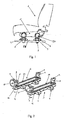
- a motor vehicle seat comprising a seat frame 11, a device 2, 3 for adjusting the tilt and height of the seat frame 11, connected with the seat frame 11, and means 4 for anchorage of the adjustment device 2, 3 to a plurality of anchorage points 5.
- the seat tilt and height adjustment device 2, 3 has rotary control members 40 and a mechanical transmission system 20.
- the adjustment device 2, 3 comprises two separate units 2, 3.
- the two separate units 2, 3 are connected to the front portion and the rear portion respectively ofthe seat frame 11, and each of these separate units 2, 3 is adapted to adjust the height of the front portion and the rear portion respectively of the seat frame 11.
- Rotation of the control means 40 provides, through the mechanical transmission system 20, selective adjustment ofthe height of the front and/or rear portion of the seat frame, hence ofthe seat tilt.
- each separate unit 2, 3 has its own rotary control member 40 and its own mechanical transmission system 20.
- each separate unit 2, 3 has its own mechanical transmission system 20, while a single rotary control member is provided, which is capable of selectively or jointly actuating the mechanical transmission systems 20 of each separate adjustment unit 2, 3.
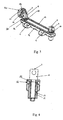
- each separate unit 2, 3 preferably comprises at least two vertically extending and axially movable adjusting pins 8.
- Each adjusting pin 8 is coupled to a rotating sleeve 12 and has a free end 9 that is hinged to the seat frame 11.
- the rotating sleeve 12 has an externally threaded portion and is in turn coupled to an internally threaded stationary bush 13.
- the adjusting pin 8 is rotably coupled to the threaded sleeve 12, that means that rotation of the rotating sleeve 12 in the stationary bush 13 does not cause rotation of the adjusting pin 8.
- the body of the adjusting pin 8 is fitted in the hole ofthe sleeve 12 with a clearance and, at its free end 9, it has a head of greater diameter than the body of the adjusting pin 8.
- rotation ofthe sleeve 12 provides adjustment of the height of the adjusting pin 8.
- the transmission means 20 of each separate unit 2, 3 preferably comprise a pulley 24 coaxial with each rotating sleeve 12 and a toothed belt 25 engaged in each pulley 24.
- Each pulley 24 is integral with the rotating sleeve 12.
- an end of the rotating sleeve 12 preferably has a not threaded portion, e.g. of polygonal shape, with a pulley 24 fitted thereon, that can transmit its rotation to the rotating sleeve 12, when coupled.
- the adjustment means 20 of each separate unit 2, 3 preferably comprise a first bevel gear 21 integral with the rotary control member 40 and a second bevel gear 22 coaxial and integral with one of the sleeves 12 of the separate unit 2, 3.
- the two bevel gears 21 and 22 are coupled with each other, so that rotation of the control member 40 is transmitted to the sleeve 12.
- the second bevel gear 22 and the pulley 24 form one single body.
- Rotation of the first sleeve 12 is in turn transmitted to the other sleeve 12 through the toothed belt 25 and pulleys 24 fitted on each sleeve 12.
- Rotation of the sleeves 12 allows synchronous axial adjustment of the adjusting pins 8 coupled thereto, and thence height adjustment of the seat frame portion 11 above the pins 8.
- the first bevel gear 21 integral with the rotary control member 40 is fitted on a horizontal mounting pin 6, which is further used to hinge the seat frame 11 to one ofthe adjusting pins 8.
- Each separate unit 2, 3 preferably comprises a metal section bar 14, which integrally houses the bushes 13 and to whom the means 4 for anchorage of the adjustment device 2, 3 to the anchorage points 5 arc connected.
- the anchorage points 5 may be directly created on the vehicle floor.
- the anchorage points 5 may be formed on sliders which are inserted in guides 55 oriented longitudinally with respect to the seat portion of the seat 11 to allow seat sliding.
- the metal section bar 14 is preferably formed of two welded channels.
- the rotary control member 40 of each separate unit 2, 3 may be a manually driven knob 50.
- the knob 50 is removably connected to the first bevel gear 21.
- the rotary control member 40 of each separate unit 2, 3 may be a rotary actuator 51, e.g. a direct current motor (not shown).
Landscapes
- Engineering & Computer Science (AREA)
- Aviation & Aerospace Engineering (AREA)
- Transportation (AREA)
- Mechanical Engineering (AREA)
- Seats For Vehicles (AREA)
- Vehicle Body Suspensions (AREA)
Applications Claiming Priority (1)
| Application Number | Priority Date | Filing Date | Title |
|---|---|---|---|
| IT002071A ITMI20052071A1 (it) | 2005-10-28 | 2005-10-28 | Sedile per autoveicolo con dispositivo di regolazione dell'assetto e dell'altezza |
Publications (3)
| Publication Number | Publication Date |
|---|---|
| EP1780071A2 true EP1780071A2 (de) | 2007-05-02 |
| EP1780071A3 EP1780071A3 (de) | 2007-11-07 |
| EP1780071B1 EP1780071B1 (de) | 2009-10-07 |
Family
ID=37736927
Family Applications (1)
| Application Number | Title | Priority Date | Filing Date |
|---|---|---|---|
| EP06022579A Not-in-force EP1780071B1 (de) | 2005-10-28 | 2006-10-30 | Autositz mit einer Vorrichtung zur Neigungs- und Höhenverstellung |
Country Status (4)
| Country | Link |
|---|---|
| EP (1) | EP1780071B1 (de) |
| AT (1) | ATE444873T1 (de) |
| DE (1) | DE602006009601D1 (de) |
| IT (1) | ITMI20052071A1 (de) |
Cited By (1)
| Publication number | Priority date | Publication date | Assignee | Title |
|---|---|---|---|---|
| EP4166386A1 (de) * | 2021-10-14 | 2023-04-19 | Ningbo Geely Automobile Research & Development Co. Ltd. | Fahrzeugsitz und verfahren zur betätigung eines fahrzeugsitzes |
Citations (4)
| Publication number | Priority date | Publication date | Assignee | Title |
|---|---|---|---|---|
| DE2006816A1 (de) * | 1970-02-14 | 1971-09-02 | Daimler Benz AG, 7000 Stuttgart Unterturkheim | Einstellbarer Sitz |
| DE2626442A1 (de) * | 1976-06-12 | 1977-12-22 | Keiper Automobiltechnik Gmbh | Hoehenverstellbarer sitz insbesondere kraftwagensitz |
| GB2141624A (en) * | 1983-06-20 | 1985-01-03 | Hammarstedt Verk Brdr | Seat adjustment device in particular for vehicle seats |
| US20010035673A1 (en) * | 2000-03-22 | 2001-11-01 | Franck Lepaule | Vehicle seat comprising a height-adjusting mechanism, and a control device for such a seat |
-
2005
- 2005-10-28 IT IT002071A patent/ITMI20052071A1/it unknown
-
2006
- 2006-10-30 EP EP06022579A patent/EP1780071B1/de not_active Not-in-force
- 2006-10-30 AT AT06022579T patent/ATE444873T1/de not_active IP Right Cessation
- 2006-10-30 DE DE602006009601T patent/DE602006009601D1/de active Active
Patent Citations (4)
| Publication number | Priority date | Publication date | Assignee | Title |
|---|---|---|---|---|
| DE2006816A1 (de) * | 1970-02-14 | 1971-09-02 | Daimler Benz AG, 7000 Stuttgart Unterturkheim | Einstellbarer Sitz |
| DE2626442A1 (de) * | 1976-06-12 | 1977-12-22 | Keiper Automobiltechnik Gmbh | Hoehenverstellbarer sitz insbesondere kraftwagensitz |
| GB2141624A (en) * | 1983-06-20 | 1985-01-03 | Hammarstedt Verk Brdr | Seat adjustment device in particular for vehicle seats |
| US20010035673A1 (en) * | 2000-03-22 | 2001-11-01 | Franck Lepaule | Vehicle seat comprising a height-adjusting mechanism, and a control device for such a seat |
Cited By (2)
| Publication number | Priority date | Publication date | Assignee | Title |
|---|---|---|---|---|
| EP4166386A1 (de) * | 2021-10-14 | 2023-04-19 | Ningbo Geely Automobile Research & Development Co. Ltd. | Fahrzeugsitz und verfahren zur betätigung eines fahrzeugsitzes |
| WO2023061331A1 (en) * | 2021-10-14 | 2023-04-20 | Ningbo Geely Automobile Research & Development Co., Ltd. | A vehicle seat and a method for operating a vehicle seat |
Also Published As
| Publication number | Publication date |
|---|---|
| DE602006009601D1 (de) | 2009-11-19 |
| EP1780071A3 (de) | 2007-11-07 |
| ITMI20052071A1 (it) | 2007-04-29 |
| ATE444873T1 (de) | 2009-10-15 |
| EP1780071B1 (de) | 2009-10-07 |
Similar Documents
| Publication | Publication Date | Title |
|---|---|---|
| DE4009127C2 (de) | Kopfstützenanordnung | |
| US20120025582A1 (en) | Seat assembly having an adjustable head restraint assembly | |
| DE10036441B4 (de) | Kopfstütze für einen Fahrzeugsitz | |
| DE102007000292B4 (de) | Sitzgerät für ein Fahrzeug | |
| DE202018102807U1 (de) | Einstellbare Kopfstützenbaugruppe | |
| EP3606823B1 (de) | Flugzeugsitzvorrichtung | |
| KR20060011935A (ko) | 시트 받침대 조정 장치 및 방법 | |
| DE602004001654T2 (de) | Vorrichtung und Methode zur Einstellung der Fahrerposition | |
| US4333627A (en) | Arrangement for moving an object | |
| DE60208858T2 (de) | Steuergerät Anordnungsstruktur für Fahrzeug | |
| DE202014105044U1 (de) | Einklemmschutzsystem für Fahrzeugsitze | |
| WO2014124630A1 (de) | Fahrzeugsitz, insbesondere für ein kraftfahrzeug | |
| DE19943707A1 (de) | Fahrzeugsitz | |
| US20020024247A1 (en) | Headrest device | |
| DE102015214297A1 (de) | Elektrisch verstellbarer Bürostuhl | |
| DE102013217918A1 (de) | Fahrzeugsitz mit einem Antrieb für Lehnen- und Kopfstützenverstellung | |
| CN112140950A (zh) | 枢转座椅总成 | |
| DE102015116480B4 (de) | Fahrzeugsitzanordnung, kraftfahrzeugsitz und befestigungsanordnung für ein fahrzeugsitzpolster | |
| DE102011016646A1 (de) | Rückenlehnenverstellvorrichtung für einen Fahrzeugsitz oder eine Fahrzeugsitzbank | |
| DE102015206759A1 (de) | Vorrichtung zum Verstellen von Rücksitz für Fahrzeug | |
| EP1780071A2 (de) | Autositz mit einer Vorrichtung zur Neigungs- und Höhenverstellung | |
| EP1147028A1 (de) | Einrichtung zur verstellung einer sitzlehne mit lastkompensation | |
| DE10146144B4 (de) | Fahrzeugsitz | |
| EP1571064B1 (de) | Einstellbarer Pedal- und Lenksäulemechanismus | |
| US6942293B2 (en) | Neck rest for the back rest of automobile seats, in particular rear seats |
Legal Events
| Date | Code | Title | Description |
|---|---|---|---|
| PUAI | Public reference made under article 153(3) epc to a published international application that has entered the european phase |
Free format text: ORIGINAL CODE: 0009012 |
|
| AK | Designated contracting states |
Kind code of ref document: A2 Designated state(s): AT BE BG CH CY CZ DE DK EE ES FI FR GB GR HU IE IS IT LI LT LU LV MC NL PL PT RO SE SI SK TR |
|
| AX | Request for extension of the european patent |
Extension state: AL BA HR MK YU |
|
| PUAL | Search report despatched |
Free format text: ORIGINAL CODE: 0009013 |
|
| AK | Designated contracting states |
Kind code of ref document: A3 Designated state(s): AT BE BG CH CY CZ DE DK EE ES FI FR GB GR HU IE IS IT LI LT LU LV MC NL PL PT RO SE SI SK TR |
|
| AX | Request for extension of the european patent |
Extension state: AL BA HR MK YU |
|
| AKX | Designation fees paid | ||
| REG | Reference to a national code |
Ref country code: DE Ref legal event code: 8566 |
|
| 17P | Request for examination filed |
Effective date: 20080722 |
|
| RBV | Designated contracting states (corrected) |
Designated state(s): AT BE BG CH CY CZ DE DK EE ES FI FR GB GR HU IE IS IT LI LT LU LV MC NL PL PT RO SE SI SK TR |
|
| 17Q | First examination report despatched |
Effective date: 20080825 |
|
| GRAP | Despatch of communication of intention to grant a patent |
Free format text: ORIGINAL CODE: EPIDOSNIGR1 |
|
| GRAS | Grant fee paid |
Free format text: ORIGINAL CODE: EPIDOSNIGR3 |
|
| GRAA | (expected) grant |
Free format text: ORIGINAL CODE: 0009210 |
|
| AK | Designated contracting states |
Kind code of ref document: B1 Designated state(s): AT BE BG CH CY CZ DE DK EE ES FI FR GB GR HU IE IS IT LI LT LU LV MC NL PL PT RO SE SI SK TR |
|
| REG | Reference to a national code |
Ref country code: GB Ref legal event code: FG4D |
|
| REG | Reference to a national code |
Ref country code: CH Ref legal event code: EP |
|
| REG | Reference to a national code |
Ref country code: IE Ref legal event code: FG4D |
|
| REF | Corresponds to: |
Ref document number: 602006009601 Country of ref document: DE Date of ref document: 20091119 Kind code of ref document: P |
|
| PG25 | Lapsed in a contracting state [announced via postgrant information from national office to epo] |
Ref country code: SI Free format text: LAPSE BECAUSE OF FAILURE TO SUBMIT A TRANSLATION OF THE DESCRIPTION OR TO PAY THE FEE WITHIN THE PRESCRIBED TIME-LIMIT Effective date: 20091007 |
|
| NLV1 | Nl: lapsed or annulled due to failure to fulfill the requirements of art. 29p and 29m of the patents act | ||
| LTIE | Lt: invalidation of european patent or patent extension |
Effective date: 20091007 |
|
| PG25 | Lapsed in a contracting state [announced via postgrant information from national office to epo] |
Ref country code: SE Free format text: LAPSE BECAUSE OF FAILURE TO SUBMIT A TRANSLATION OF THE DESCRIPTION OR TO PAY THE FEE WITHIN THE PRESCRIBED TIME-LIMIT Effective date: 20091007 Ref country code: PT Free format text: LAPSE BECAUSE OF FAILURE TO SUBMIT A TRANSLATION OF THE DESCRIPTION OR TO PAY THE FEE WITHIN THE PRESCRIBED TIME-LIMIT Effective date: 20100208 Ref country code: IS Free format text: LAPSE BECAUSE OF FAILURE TO SUBMIT A TRANSLATION OF THE DESCRIPTION OR TO PAY THE FEE WITHIN THE PRESCRIBED TIME-LIMIT Effective date: 20100207 Ref country code: FI Free format text: LAPSE BECAUSE OF FAILURE TO SUBMIT A TRANSLATION OF THE DESCRIPTION OR TO PAY THE FEE WITHIN THE PRESCRIBED TIME-LIMIT Effective date: 20091007 Ref country code: LT Free format text: LAPSE BECAUSE OF FAILURE TO SUBMIT A TRANSLATION OF THE DESCRIPTION OR TO PAY THE FEE WITHIN THE PRESCRIBED TIME-LIMIT Effective date: 20091007 Ref country code: ES Free format text: LAPSE BECAUSE OF FAILURE TO SUBMIT A TRANSLATION OF THE DESCRIPTION OR TO PAY THE FEE WITHIN THE PRESCRIBED TIME-LIMIT Effective date: 20100118 |
|
| PG25 | Lapsed in a contracting state [announced via postgrant information from national office to epo] |
Ref country code: MC Free format text: LAPSE BECAUSE OF NON-PAYMENT OF DUE FEES Effective date: 20091031 Ref country code: LV Free format text: LAPSE BECAUSE OF FAILURE TO SUBMIT A TRANSLATION OF THE DESCRIPTION OR TO PAY THE FEE WITHIN THE PRESCRIBED TIME-LIMIT Effective date: 20091007 Ref country code: PL Free format text: LAPSE BECAUSE OF FAILURE TO SUBMIT A TRANSLATION OF THE DESCRIPTION OR TO PAY THE FEE WITHIN THE PRESCRIBED TIME-LIMIT Effective date: 20091007 |
|
| PG25 | Lapsed in a contracting state [announced via postgrant information from national office to epo] |
Ref country code: BE Free format text: LAPSE BECAUSE OF FAILURE TO SUBMIT A TRANSLATION OF THE DESCRIPTION OR TO PAY THE FEE WITHIN THE PRESCRIBED TIME-LIMIT Effective date: 20091007 Ref country code: AT Free format text: LAPSE BECAUSE OF FAILURE TO SUBMIT A TRANSLATION OF THE DESCRIPTION OR TO PAY THE FEE WITHIN THE PRESCRIBED TIME-LIMIT Effective date: 20091007 |
|
| PG25 | Lapsed in a contracting state [announced via postgrant information from national office to epo] |
Ref country code: EE Free format text: LAPSE BECAUSE OF FAILURE TO SUBMIT A TRANSLATION OF THE DESCRIPTION OR TO PAY THE FEE WITHIN THE PRESCRIBED TIME-LIMIT Effective date: 20091007 Ref country code: NL Free format text: LAPSE BECAUSE OF FAILURE TO SUBMIT A TRANSLATION OF THE DESCRIPTION OR TO PAY THE FEE WITHIN THE PRESCRIBED TIME-LIMIT Effective date: 20091007 Ref country code: RO Free format text: LAPSE BECAUSE OF FAILURE TO SUBMIT A TRANSLATION OF THE DESCRIPTION OR TO PAY THE FEE WITHIN THE PRESCRIBED TIME-LIMIT Effective date: 20091007 Ref country code: BG Free format text: LAPSE BECAUSE OF FAILURE TO SUBMIT A TRANSLATION OF THE DESCRIPTION OR TO PAY THE FEE WITHIN THE PRESCRIBED TIME-LIMIT Effective date: 20100107 Ref country code: DK Free format text: LAPSE BECAUSE OF FAILURE TO SUBMIT A TRANSLATION OF THE DESCRIPTION OR TO PAY THE FEE WITHIN THE PRESCRIBED TIME-LIMIT Effective date: 20091007 |
|
| PLBE | No opposition filed within time limit |
Free format text: ORIGINAL CODE: 0009261 |
|
| STAA | Information on the status of an ep patent application or granted ep patent |
Free format text: STATUS: NO OPPOSITION FILED WITHIN TIME LIMIT |
|
| PG25 | Lapsed in a contracting state [announced via postgrant information from national office to epo] |
Ref country code: CZ Free format text: LAPSE BECAUSE OF FAILURE TO SUBMIT A TRANSLATION OF THE DESCRIPTION OR TO PAY THE FEE WITHIN THE PRESCRIBED TIME-LIMIT Effective date: 20091007 Ref country code: SK Free format text: LAPSE BECAUSE OF FAILURE TO SUBMIT A TRANSLATION OF THE DESCRIPTION OR TO PAY THE FEE WITHIN THE PRESCRIBED TIME-LIMIT Effective date: 20091007 |
|
| 26N | No opposition filed |
Effective date: 20100708 |
|
| PG25 | Lapsed in a contracting state [announced via postgrant information from national office to epo] |
Ref country code: GR Free format text: LAPSE BECAUSE OF FAILURE TO SUBMIT A TRANSLATION OF THE DESCRIPTION OR TO PAY THE FEE WITHIN THE PRESCRIBED TIME-LIMIT Effective date: 20100108 Ref country code: IE Free format text: LAPSE BECAUSE OF NON-PAYMENT OF DUE FEES Effective date: 20091030 |
|
| PG25 | Lapsed in a contracting state [announced via postgrant information from national office to epo] |
Ref country code: LU Free format text: LAPSE BECAUSE OF NON-PAYMENT OF DUE FEES Effective date: 20091030 |
|
| REG | Reference to a national code |
Ref country code: CH Ref legal event code: PL |
|
| GBPC | Gb: european patent ceased through non-payment of renewal fee |
Effective date: 20101030 |
|
| PG25 | Lapsed in a contracting state [announced via postgrant information from national office to epo] |
Ref country code: HU Free format text: LAPSE BECAUSE OF FAILURE TO SUBMIT A TRANSLATION OF THE DESCRIPTION OR TO PAY THE FEE WITHIN THE PRESCRIBED TIME-LIMIT Effective date: 20100408 |
|
| PG25 | Lapsed in a contracting state [announced via postgrant information from national office to epo] |
Ref country code: LI Free format text: LAPSE BECAUSE OF NON-PAYMENT OF DUE FEES Effective date: 20101031 Ref country code: CH Free format text: LAPSE BECAUSE OF NON-PAYMENT OF DUE FEES Effective date: 20101031 |
|
| PG25 | Lapsed in a contracting state [announced via postgrant information from national office to epo] |
Ref country code: TR Free format text: LAPSE BECAUSE OF FAILURE TO SUBMIT A TRANSLATION OF THE DESCRIPTION OR TO PAY THE FEE WITHIN THE PRESCRIBED TIME-LIMIT Effective date: 20091007 Ref country code: GB Free format text: LAPSE BECAUSE OF NON-PAYMENT OF DUE FEES Effective date: 20101030 |
|
| PG25 | Lapsed in a contracting state [announced via postgrant information from national office to epo] |
Ref country code: CY Free format text: LAPSE BECAUSE OF FAILURE TO SUBMIT A TRANSLATION OF THE DESCRIPTION OR TO PAY THE FEE WITHIN THE PRESCRIBED TIME-LIMIT Effective date: 20091007 |
|
| PGFP | Annual fee paid to national office [announced via postgrant information from national office to epo] |
Ref country code: FR Payment date: 20131029 Year of fee payment: 8 Ref country code: DE Payment date: 20131029 Year of fee payment: 8 |
|
| PGFP | Annual fee paid to national office [announced via postgrant information from national office to epo] |
Ref country code: IT Payment date: 20131030 Year of fee payment: 8 |
|
| REG | Reference to a national code |
Ref country code: DE Ref legal event code: R119 Ref document number: 602006009601 Country of ref document: DE |
|
| PG25 | Lapsed in a contracting state [announced via postgrant information from national office to epo] |
Ref country code: DE Free format text: LAPSE BECAUSE OF NON-PAYMENT OF DUE FEES Effective date: 20150501 |
|
| REG | Reference to a national code |
Ref country code: FR Ref legal event code: ST Effective date: 20150630 |
|
| PG25 | Lapsed in a contracting state [announced via postgrant information from national office to epo] |
Ref country code: IT Free format text: LAPSE BECAUSE OF NON-PAYMENT OF DUE FEES Effective date: 20141030 Ref country code: FR Free format text: LAPSE BECAUSE OF NON-PAYMENT OF DUE FEES Effective date: 20141031 |