EP1777458B1 - Improvement of the performances of a combustion chamber by multiperforating the walls - Google Patents
Improvement of the performances of a combustion chamber by multiperforating the walls Download PDFInfo
- Publication number
- EP1777458B1 EP1777458B1 EP06120816.1A EP06120816A EP1777458B1 EP 1777458 B1 EP1777458 B1 EP 1777458B1 EP 06120816 A EP06120816 A EP 06120816A EP 1777458 B1 EP1777458 B1 EP 1777458B1
- Authority
- EP
- European Patent Office
- Prior art keywords
- holes
- wall
- combustion chamber
- bores
- cooling
- Prior art date
- Legal status (The legal status is an assumption and is not a legal conclusion. Google has not performed a legal analysis and makes no representation as to the accuracy of the status listed.)
- Active
Links
Images
Classifications
-
- F—MECHANICAL ENGINEERING; LIGHTING; HEATING; WEAPONS; BLASTING
- F23—COMBUSTION APPARATUS; COMBUSTION PROCESSES
- F23R—GENERATING COMBUSTION PRODUCTS OF HIGH PRESSURE OR HIGH VELOCITY, e.g. GAS-TURBINE COMBUSTION CHAMBERS
- F23R3/00—Continuous combustion chambers using liquid or gaseous fuel
- F23R3/002—Wall structures
-
- F—MECHANICAL ENGINEERING; LIGHTING; HEATING; WEAPONS; BLASTING
- F23—COMBUSTION APPARATUS; COMBUSTION PROCESSES
- F23R—GENERATING COMBUSTION PRODUCTS OF HIGH PRESSURE OR HIGH VELOCITY, e.g. GAS-TURBINE COMBUSTION CHAMBERS
- F23R3/00—Continuous combustion chambers using liquid or gaseous fuel
- F23R3/02—Continuous combustion chambers using liquid or gaseous fuel characterised by the air-flow or gas-flow configuration
- F23R3/04—Air inlet arrangements
- F23R3/06—Arrangement of apertures along the flame tube
-
- F—MECHANICAL ENGINEERING; LIGHTING; HEATING; WEAPONS; BLASTING
- F23—COMBUSTION APPARATUS; COMBUSTION PROCESSES
- F23R—GENERATING COMBUSTION PRODUCTS OF HIGH PRESSURE OR HIGH VELOCITY, e.g. GAS-TURBINE COMBUSTION CHAMBERS
- F23R2900/00—Special features of, or arrangements for continuous combustion chambers; Combustion processes therefor
- F23R2900/03041—Effusion cooled combustion chamber walls or domes
-
- F—MECHANICAL ENGINEERING; LIGHTING; HEATING; WEAPONS; BLASTING
- F23—COMBUSTION APPARATUS; COMBUSTION PROCESSES
- F23R—GENERATING COMBUSTION PRODUCTS OF HIGH PRESSURE OR HIGH VELOCITY, e.g. GAS-TURBINE COMBUSTION CHAMBERS
- F23R2900/00—Special features of, or arrangements for continuous combustion chambers; Combustion processes therefor
- F23R2900/03042—Film cooled combustion chamber walls or domes
Definitions
- the present invention relates to the general field of turbomachine combustion chambers. It relates more particularly to an annular wall for combustion chamber cooled by a so-called "multiperforation" process.
- annular turbomachine combustion chamber is formed of an inner annular wall and an outer annular wall which are connected upstream by a transverse wall forming a chamber bottom.
- the inner and outer walls are each provided with a plurality of holes and various orifices allowing air circulating around the combustion chamber to penetrate inside thereof.
- so-called “primary” and “dilution” holes are formed in these walls to convey air inside the combustion chamber.
- the air passing through the primary holes helps to create an air / fuel mixture that is burned in the chamber, while the air from the dilution holes is intended to promote the dilution of the same air / fuel mixture.
- the inner and outer walls which are generally metallic, are subject to the high temperatures of the gases from the combustion of the air / fuel mixture.
- additional holes called multiperforation holes are also drilled through the walls over their entire surface. These multiperforation holes allow the air circulating outside the chamber to penetrate inside thereof by forming along the walls of the cooling air films.
- annular wall of turbomachine combustion chamber being provided with a plurality of primary holes and dilution holes. Cooling orifices are distributed in circumferential rows, the number of these orifices being identical in each row. A plurality of bores are disposed directly downstream of the primary holes and the dilution holes. These holes are distributed in circumferential rows. The bores of the same row have a substantially identical diameter, and are spaced a constant pitch throughout the row. Variations in inclination or frequency of said holes relative to the other cooling orifices are not discussed in the document.
- Patent documents EP 1001222 and US 5775108 describe similar annular combustion chamber walls, and there are discussed variations in number (EP) or inclination (US) of the cooling orifices.
- the main object of the present invention is therefore to overcome such drawbacks by proposing an annular wall of a combustion chamber provided with additional bores intended to cool the zones situated directly downstream of the primary and dilution holes.
- annular wall of a turbomachine combustion chamber according to claim 1.
- intrinsic characteristics of the holes we mean the number, the inclination and the diameter of these holes.
- the presence of holes having intrinsic characteristics different from those of the cooling orifices and arranged directly downstream of the primary and dilution holes makes it possible to ensure effective cooling of these areas. Any risk of formation of cracks is thus avoided.
- the specific bores are distributed in circumferential rows, have the same diameter and are spaced a constant pitch which greatly facilitates drilling operations and thus reduces the costs and manufacturing time of the wall.
- the number of holes in the same row may be different from the number of cooling orifices of the adjacent rows, and / or the inclination of the bores of the same row relative to a normal to the wall may be different from that of the cooling holes in adjacent rows.
- the diameter of the bores of the same row may be different from that of the cooling holes of the adjacent rows.
- the present invention also relates to a combustion chamber and a turbomachine (having a combustion chamber) comprising an annular wall as defined above.
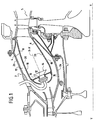
- the figure 1 illustrates a combustion chamber for a turbomachine.
- a turbomachine comprises in particular a compression section (not shown) in which air is compressed before being injected into a chamber housing 2, then into a combustion chamber 4 mounted inside thereof.
- Compressed air is introduced into the combustion chamber and mixed with fuel before being burned.
- the gases resulting from this combustion are then directed to a high-pressure turbine 5 disposed at the outlet of the combustion chamber 4.
- the combustion chamber 4 is of annular type. It is formed of an inner annular wall 6 and an outer annular wall 8 which are connected upstream by a transverse wall 10 forming a chamber bottom.
- the inner 6 and outer 8 walls extend along a longitudinal axis X-X slightly inclined relative to the longitudinal axis Y-Y of the turbomachine.
- the chamber bottom 10 is provided with a plurality of openings 12 in which fuel injectors 14 are mounted.
- the chamber casing 2 which is formed of an inner casing 2a and an outer casing 2b, furnishes with the combustion chamber 4 an annular space 16 in which compressed air for combustion is admitted to the chamber. dilution and cooling of the chamber.
- the inner 6 and outer 8 walls each have a cold side 6a, 8a disposed on the side of the annular space 16 in which the compressed air circulates and a hot side 6b, 8b facing the inside of the combustion chamber 4 ( figure 3 ).
- the combustion chamber 4 is divided into a so-called “primary” zone (or combustion zone) and a so-called “secondary” zone (or dilution zone) located downstream of the previous one (the downstream means with respect to the general direction of flow of gases from the combustion of the air / fuel mixture inside the combustion chamber).
- the air which supplies the primary zone of the combustion chamber 4 is introduced by one or more circumferential rows of primary holes 18 made in the inner and outer walls 6 of the chamber.
- the air supplying the secondary zone of the chamber it borrows a plurality of dilution holes 20 also formed in the inner 6 and outer 8 walls. These dilution holes 20 are aligned in one or more circumferential rows which are axially offset. downstream from the rows of primary holes 18.
- the primary holes 18 and the dilution holes 20 are distributed on the inner 6 and outer 8 walls in rows extending over the entire circumference of the walls.
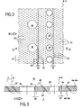
- a plurality of cooling orifices 22 are provided ( Figures 2 and 3 ).
- These orifices 22, which provide a cooling of the walls 6, 8 by multiperforation, are distributed in a plurality of circumferential rows spaced axially from each other. These rows of multiperforation holes cover almost the entire surface of the walls 6, 8 of the chamber.
- the number and the diameter d1 of the cooling orifices 22 are identical in each of the rows.
- the pitch p1 between two orifices 22 of the same row is also identical throughout the row.
- the adjacent rows of cooling orifices are arranged so that the orifices 22 are arranged in staggered rows as shown in FIG. figure 1 .
- the cooling orifices 22 generally have an angle of inclination ⁇ with respect to a normal N to the annular wall 6, 8 through which they are pierced.
- This inclination ⁇ allows the air passing through these orifices to form a film of air along the hot side 6b, 8b of the annular wall 6, 8.
- it also makes it possible to increase the surface area. of the annular wall which is cooled.
- the inclination ⁇ of the cooling orifices 22 is directed so that the film of air thus formed flows in the direction of flow of the combustion gases inside the chamber (shown schematically by the arrow on the figure 3 ).
- the diameter d 1 of the cooling orifices 22 may be between 0.3 and 1. mm, the pitch p1 between 1 and 10 mm and their inclination ⁇ between -80 ° and + 80 °.
- primary holes 18 and the dilution holes 20 have a diameter of the order of 5 to 20 mm.
- each annular wall 6, 8 of the combustion chamber further comprises a plurality of bores 24 which are arranged directly downstream of the primary holes 18 and dilution 20 and which are distributed in circumferential rows.
- the bores 24 of the same row have a substantially identical diameter d2 , are spaced at a constant pitch P2 and have intrinsic characteristics different from those of the cooling orifices 22 of adjacent rows.
- these holes 24 are thus distributed in one or more rows (for example from 1 to 3 rows) which are arranged directly downstream of said hole 18, 20.
- the intrinsic characteristics of these holes 24 are different from those of the cooling orifices 22, that is to say that the number of holes in the same row is different from that of a row of cooling orifices, and / or or the inclination of the bores of the same row with respect to a normal N to the wall 6, 8 is different from that of the cooling orifices, and / or the diameter d2 of the bores of the same row is different from that of d1 22. It should be noted that these three intrinsic characteristics of the holes 24 can be added.
- the number of bores 24 on the same row may be, over the entire circumference of the wall, of the order of 860 when the number of cooling orifices 22 is of the order of 576. .
- the inclination of the bores 24 relative to a normal to the walls 6, 8 is zero (that is to say that the holes are substantially perpendicular to the walls), while the inclination ⁇ of the cooling orifices 22 relative to at this same normal is between 30 ° and 70 °.
- the bores 24 of the same row have an identical diameter d2 and are spaced by a constant pitch p2 .
- Such holes are typically made by laser using a machine programmed according to the position of each of the holes to be made.
- the characteristics of the holes according to the invention make it possible, with respect to a localized treatment (for which the bores are made only in the direct vicinity of each of the primary and dilution holes), to considerably simplify the programming of the machine, and thus to reduce the costs and manufacturing delays.
Landscapes
- Engineering & Computer Science (AREA)
- Chemical & Material Sciences (AREA)
- Combustion & Propulsion (AREA)
- Mechanical Engineering (AREA)
- General Engineering & Computer Science (AREA)
- Turbine Rotor Nozzle Sealing (AREA)
Description
La présente invention se rapporte au domaine général des chambres de combustion de turbomachine. Elle vise plus particulièrement une paroi annulaire pour chambre de combustion refroidie par un procédé dit de « multiperforation ».The present invention relates to the general field of turbomachine combustion chambers. It relates more particularly to an annular wall for combustion chamber cooled by a so-called "multiperforation" process.
Typiquement, une chambre de combustion annulaire de turbomachine est formée d'une paroi annulaire interne et d'une paroi annulaire externe qui sont reliées en amont par une paroi transversale formant fond de chambre.Typically, an annular turbomachine combustion chamber is formed of an inner annular wall and an outer annular wall which are connected upstream by a transverse wall forming a chamber bottom.
Les parois interne et externe sont chacune pourvues d'une pluralité de trous et d'orifices divers permettant à de l'air circulant autour de la chambre de combustion de pénétrer à l'intérieur de celle-ci.The inner and outer walls are each provided with a plurality of holes and various orifices allowing air circulating around the combustion chamber to penetrate inside thereof.
Ainsi, des trous dits « primaires » et « de dilution » sont formés dans ces parois pour acheminer de l'air à l'intérieur de la chambre de combustion. L'air empruntant les trous primaires contribue à créer un mélange air/carburant qui est brûlé dans la chambre, tandis que l'air provenant des trous de dilution est destiné à favoriser la dilution de ce même mélange air/carburant.Thus, so-called "primary" and "dilution" holes are formed in these walls to convey air inside the combustion chamber. The air passing through the primary holes helps to create an air / fuel mixture that is burned in the chamber, while the air from the dilution holes is intended to promote the dilution of the same air / fuel mixture.
Les parois interne et externe, qui sont généralement métalliques, sont soumises aux températures élevées des gaz provenant de la combustion du mélange air/carburant. Afin d'assurer leur refroidissement, des orifices supplémentaires dits de multiperforation sont également percés au travers des parois sur toute leur surface. Ces orifices de multiperforation permettent à l'air circulant à l'extérieur de la chambre de pénétrer à l'intérieur de celle-ci en formant le long des parois des films d'air de refroidissement.The inner and outer walls, which are generally metallic, are subject to the high temperatures of the gases from the combustion of the air / fuel mixture. To ensure their cooling, additional holes called multiperforation holes are also drilled through the walls over their entire surface. These multiperforation holes allow the air circulating outside the chamber to penetrate inside thereof by forming along the walls of the cooling air films.
En pratique, il a été constaté que la zone des parois interne et externe qui est située directement en aval de chacun des trous primaires et de dilution bénéficie d'un faible niveau refroidissement avec le risque de formation de criques que cela implique.In practice, it has been found that the area of the inner and outer walls which is located directly downstream of each of the primary and dilution holes has a low cooling level with the risk of formation of cracks that implies.
Afin de résoudre ce problème, le document
Du document de
La présente invention a donc pour but principal de pallier de tels inconvénients en proposant une paroi annulaire de chambre de combustion munie de perçages supplémentaires destinés à refroidir les zones situées directement en aval des trous primaires et de dilution.The main object of the present invention is therefore to overcome such drawbacks by proposing an annular wall of a combustion chamber provided with additional bores intended to cool the zones situated directly downstream of the primary and dilution holes.
A cet effet, il est prévu une paroi annulaire de chambre de combustion de turbomachine. selon la revendication 1.For this purpose, there is provided an annular wall of a turbomachine combustion chamber. according to claim 1.
Par caractéristiques intrinsèques des perçages, on entend le nombre, l'inclinaison et le diamètre de ces perçages. La présence de perçages ayant des caractéristiques intrinsèques différentes de celles des orifices de refroidissement et disposés directement en aval des trous primaires et de dilution permet d'assurer un refroidissement efficace de ces zones. Tout risque de formation de criques est ainsi évité. En outre, les perçages spécifiques sont répartis selon des rangées circonférentielles, présentent un même diamètre et sont espacés d'un pas constant ce qui facilite grandement les opérations de perçage et réduit donc les coûts et les délais de fabrication de la paroi.By intrinsic characteristics of the holes, we mean the number, the inclination and the diameter of these holes. The presence of holes having intrinsic characteristics different from those of the cooling orifices and arranged directly downstream of the primary and dilution holes makes it possible to ensure effective cooling of these areas. Any risk of formation of cracks is thus avoided. In addition, the specific bores are distributed in circumferential rows, have the same diameter and are spaced a constant pitch which greatly facilitates drilling operations and thus reduces the costs and manufacturing time of the wall.
Selon l'invention, le nombre de perçages d'une même rangée peut être différent du nombre d'orifices de refroidissement des rangées adjacentes, et/ou l'inclinaison des perçages d'une même rangée par rapport à une normale à la paroi peut être différente de celle des orifices de refroidissement des rangées adjacentes.According to the invention, the number of holes in the same row may be different from the number of cooling orifices of the adjacent rows, and / or the inclination of the bores of the same row relative to a normal to the wall may be different from that of the cooling holes in adjacent rows.
Le diamètre des perçages d'une même rangée peut être différent de celui des orifices de refroidissement des rangées adjacentes.The diameter of the bores of the same row may be different from that of the cooling holes of the adjacent rows.
La présente invention a également pour objet une chambre de combustion et une turbomachine (ayant une chambre de combustion) comportant une paroi annulaire telle que définie précédemment.The present invention also relates to a combustion chamber and a turbomachine (having a combustion chamber) comprising an annular wall as defined above.
D'autres caractéristiques et avantages de la présente invention ressortiront de la description faite ci-dessous, en référence aux dessins annexés qui en illustrent un exemple de réalisation dépourvu de tout caractère limitatif. Sur les figures :
- la
figure 1 est une vue en coupe longitudinale d'une chambre de combustion de turbomachine dans son environnement ; - la
figure 2 est une vue partielle et en développé de l'une des parois annulaires de la chambre de combustion de lafigure 1 selon un mode de réalisation de l'invention ; et - la
figure 3 est une vue en coupe selon III-III de lafigure 2 .
- the
figure 1 is a longitudinal sectional view of a turbomachine combustion chamber in its environment; - the
figure 2 is a partial and developed view of one of the annular walls of the combustion chamber of thefigure 1 according to one embodiment of the invention; and - the
figure 3 is a sectional view along III-III of thefigure 2 .
La
L'air comprimé est introduit dans la chambre de combustion et mélangé à du carburant avant d'y être brûlé. Les gaz issus de cette combustion sont alors dirigés vers une turbine haute-pression 5 disposée en sortie de la chambre de combustion 4.Compressed air is introduced into the combustion chamber and mixed with fuel before being burned. The gases resulting from this combustion are then directed to a high-
La chambre de combustion 4 est de type annulaire. Elle est formée d'une paroi annulaire interne 6 et d'une paroi annulaire externe 8 qui sont réunies en amont par une paroi transversale 10 formant fond de chambre.The combustion chamber 4 is of annular type. It is formed of an inner
Les parois interne 6 et externe 8 s'étendent selon un axe longitudinal X-X légèrement incliné par rapport à l'axe longitudinal Y-Y de la turbomachine. Le fond de chambre 10 est pourvu d'une pluralité d'ouvertures 12 dans lesquelles sont montés des injecteurs de carburant 14.The inner 6 and outer 8 walls extend along a longitudinal axis X-X slightly inclined relative to the longitudinal axis Y-Y of the turbomachine. The
Le carter de chambre 2, qui est formé d'une enveloppe interne 2a et d'une enveloppe externe 2b, ménage avec la chambre de combustion 4 un espace annulaire 16 dans lequel est admis de l'air comprimé destiné à la combustion, à la dilution et au refroidissement de la chambre.The
Les parois interne 6 et externe 8 présentent chacune un côté froid 6a, 8a disposé du côté de l'espace annulaire 16 dans lequel circule l'air comprimé et un côté chaud 6b, 8b tourné vers l'intérieur de la chambre de combustion 4 (
La chambre de combustion 4 se divise en une zone dite « primaire » (ou zone de combustion) et une zone dite « secondaire » (ou zone de dilution) située en aval de la précédente (l'aval s'entend par rapport à la direction générale d'écoulement des gaz issus de la combustion du mélange air/carburant à l'intérieur de la chambre de combustion).The combustion chamber 4 is divided into a so-called "primary" zone (or combustion zone) and a so-called "secondary" zone (or dilution zone) located downstream of the previous one (the downstream means with respect to the general direction of flow of gases from the combustion of the air / fuel mixture inside the combustion chamber).
L'air qui alimente la zone primaire de la chambre de combustion 4 est introduit par une ou plusieurs rangées circonférentielles de trous primaires 18 pratiqués dans les parois interne 6 et externe 8 de la chambre. Quant à l'air alimentant la zone secondaire de la chambre, il emprunte une pluralité de trous de dilution 20 également formés dans les parois interne 6 et externe 8. Ces trous de dilution 20 sont alignés selon une ou plusieurs rangées circonférentielles qui sont décalées axialement vers l'aval par rapport aux rangées des trous primaires 18.The air which supplies the primary zone of the combustion chamber 4 is introduced by one or more circumferential rows of
Les trous primaires 18 et les trous de dilution 20 sont répartis sur les parois interne 6 et externe 8 selon des rangées s'étendant sur toute la circonférence des parois.The
Afin de refroidir les parois interne 6 et externe 8 de la chambre de combustion qui sont soumises aux températures élevées des gaz de combustion, il est prévu une pluralité d'orifices de refroidissement 22 (
Ces orifices 22, qui assurent un refroidissement des parois 6, 8 par multiperforation, sont répartis selon une pluralité de rangées circonférentielles espacées axialement les unes des autres. Ces rangées d'orifices de multiperforation couvrent presque toute la surface des parois 6, 8 de la chambre.These
Le nombre et le diamètre d1 des orifices de refroidissement 22 sont identiques dans chacune des rangées. Le pas p1 entre deux orifices 22 d'une même rangée est également identique sur toute la rangée. Par ailleurs, les rangées adjacentes d'orifices de refroidissement sont arrangées de façon à ce que les orifices 22 soient disposés en quinconce comme représenté sur la
Comme illustré sur la
En outre, l'inclinaison α des orifices de refroidissement 22 est dirigée de sorte que le film d'air ainsi formé s'écoule dans le sens d'écoulement des gaz de combustion à l'intérieur de la chambre (schématisé par la flèche sur la
A titre d'exemple, pour une paroi annulaire 6, 8 réalisée en matériau métallique ou céramique et ayant une épaisseur comprise entre 0,8 et 3,5mm, le diamètre d1 des orifices de refroidissement 22 peut être compris entre 0,3 et 1 mm, le pas p1 compris entre 1 et 10 mm et leur inclinaison α comprise entre -80° et +80°. A titre de comparaison, pour une paroi annulaire ayant les même caractéristiques, les trous primaires 18 et les trous de dilution 20 possèdent un diamètre de l'ordre de 5 à 20 mm.By way of example, for an
Selon l'invention, chaque paroi annulaire 6, 8 de la chambre de combustion comporte en outre une pluralité de perçages 24 qui sont disposés directement en aval des trous primaires 18 et de dilution 20 et qui sont répartis selon des rangées circonférentielles.According to the invention, each
Les perçages 24 d'une même rangée présentent un diamètre d2 sensiblement identique, sont espacés d'un pas p2 constant et présentent des caractéristiques intrinsèques différentes de celles des orifices de refroidissement 22 des rangées adjacentes.The
Pour chaque trou primaire 18 et de dilution 20, ces perçages 24 sont ainsi répartis selon une ou plusieurs rangées (par exemple de 1 à 3 rangées) qui sont disposées directement en aval dudit trou 18, 20.For each
Les caractéristiques intrinsèques de ces perçages 24 sont différentes de celles des orifices de refroidissement 22, c'est-à-dire que le nombre de perçages d'une même rangée est différent de celui d'une rangée d'orifices de refroidissement, et/ou l'inclinaison des perçages d'une même rangée par rapport à une normale N à la paroi 6, 8 est différente de celle des orifices de refroidissement, et/ou le diamètre d2 des perçages d'une même rangée est différent de celui d1 des orifices de refroidissement 22. Il est à noter que ces trois caractéristiques intrinsèques des perçages 24 peuvent s'additionner.The intrinsic characteristics of these
Ainsi, selon un exemple de réalisation, le nombre de perçages 24 sur une même rangée peut être, sur toute la circonférence de la paroi, de l'ordre de 860 lorsque le nombre d'orifices de refroidissement 22 est de l'ordre de 576.Thus, according to an exemplary embodiment, the number of
Selon un autre exemple de réalisation illustré sur la
Comme indiqué précédemment, les perçages 24 d'une même rangée présentent un diamètre d2 identique et sont espacés d'un pas p2 constant. De tels perçages sont typiquement réalisés au laser à l'aide d'une machine programmée en fonction de la position de chacun des perçages à réaliser. Aussi, les caractéristiques des perçages selon l'invention permettent, par rapport à un traitement localisé (pour lequel les perçages sont réalisés uniquement dans le voisinage direct de chacun des trous primaires et de dilution), de simplifier considérablement la programmation de la machine, et donc de réduire les coûts et les délais de fabrication.As indicated above, the
Claims (3)
- An annular wall (6, 8) for a combustion chamber (4) of a turbomachine, the wall having a cold side (6a, 8a) and a hot side (6b, 8b), said wall being provided:with a plurality of primary holes (18) and of dilution holes (20) for allowing the air flowing over the cold side (6a, 8a) of the wall (6, 8) to penetrate to the hot side (6b, 8b) in order respectively to enable combustion and to provide dilution of an air/fuel mixture, the primary holes (18) and the dilution holes (20) being distributed in circumferential rows;a plurality of cooling orifices (22) for enabling the air flowing over the cold side (6a, 8a) of the wall (6, 8) to penetrate to the hot side (6b, 8b) in order to form a film of cooling air along said wall, said cooling orifices (22) being distributed in a plurality of circumferential rows that are spaced apart axially from one another, the number of cooling orifices (22) being identical in each of the rows; anda plurality of bores (24) disposed immediately downstream from the primary holes (18) and from the dilution holes (20) and distributed in circumferential rows, the bores (24) in any one row presenting a substantially identical diameter (d2) and being spaced apart at a constant pitch (p2),the number of bores (24) in a given row being different from the number of cooling orifices (22) in the adjacent rows, and/orthe angle of inclination of the bores (24) in a given row relative to a normal (N) of the wall being different from the angle of the inclination of the cooling orifices (22) of the adjacent rows.
- A turbomachine combustion chamber (4) including at least one annular wall (6, 8) according to claim 1.
- A turbomachine including a combustion chamber (4) having at least one annular wall (6, 8) according to claim 1.
Applications Claiming Priority (1)
| Application Number | Priority Date | Filing Date | Title |
|---|---|---|---|
| FR0510584A FR2892180B1 (en) | 2005-10-18 | 2005-10-18 | IMPROVING THE PERFOMANCE OF A COMBUSTION CHAMBER BY MULTIPERFORATING THE WALLS |
Publications (2)
| Publication Number | Publication Date |
|---|---|
| EP1777458A1 EP1777458A1 (en) | 2007-04-25 |
| EP1777458B1 true EP1777458B1 (en) | 2015-08-12 |
Family
ID=36263914
Family Applications (1)
| Application Number | Title | Priority Date | Filing Date |
|---|---|---|---|
| EP06120816.1A Active EP1777458B1 (en) | 2005-10-18 | 2006-09-18 | Improvement of the performances of a combustion chamber by multiperforating the walls |
Country Status (4)
| Country | Link |
|---|---|
| US (1) | US7748222B2 (en) |
| EP (1) | EP1777458B1 (en) |
| FR (1) | FR2892180B1 (en) |
| RU (1) | RU2413134C2 (en) |
Families Citing this family (34)
| Publication number | Priority date | Publication date | Assignee | Title |
|---|---|---|---|---|
| US7614235B2 (en) * | 2005-03-01 | 2009-11-10 | United Technologies Corporation | Combustor cooling hole pattern |
| US8171634B2 (en) * | 2007-07-09 | 2012-05-08 | Pratt & Whitney Canada Corp. | Method of producing effusion holes |
| US7905094B2 (en) * | 2007-09-28 | 2011-03-15 | Honeywell International Inc. | Combustor systems with liners having improved cooling hole patterns |
| FR2922630B1 (en) * | 2007-10-22 | 2015-11-13 | Snecma | COMBUSTION CHAMBER WALL WITH OPTIMIZED DILUTION AND COOLING, COMBUSTION CHAMBER AND TURBOMACHINE WHILE ENHANCED |
| FR2922629B1 (en) * | 2007-10-22 | 2009-12-25 | Snecma | COMBUSTION CHAMBER WITH OPTIMIZED DILUTION AND TURBOMACHINE WHILE MUNIED |
| US8616004B2 (en) * | 2007-11-29 | 2013-12-31 | Honeywell International Inc. | Quench jet arrangement for annular rich-quench-lean gas turbine combustors |
| US8127554B2 (en) * | 2007-11-29 | 2012-03-06 | Honeywell International Inc. | Quench jet arrangement for annular rich-quench-lean gas turbine combustors |
| US8056342B2 (en) * | 2008-06-12 | 2011-11-15 | United Technologies Corporation | Hole pattern for gas turbine combustor |
| US8091367B2 (en) * | 2008-09-26 | 2012-01-10 | Pratt & Whitney Canada Corp. | Combustor with improved cooling holes arrangement |
| US8438856B2 (en) * | 2009-03-02 | 2013-05-14 | General Electric Company | Effusion cooled one-piece can combustor |
| FR2972027B1 (en) * | 2011-02-25 | 2013-03-29 | Snecma | ANNULAR TURBOMACHINE COMBUSTION CHAMBER COMPRISING IMPROVED DILUTION ORIFICES |
| FR2974162B1 (en) * | 2011-04-14 | 2018-04-13 | Safran Aircraft Engines | FLAME TUBE VIROLE IN A TURBOMACHINE COMBUSTION CHAMBER |
| FR2975465B1 (en) * | 2011-05-19 | 2018-03-09 | Safran Aircraft Engines | WALL FOR TURBOMACHINE COMBUSTION CHAMBER COMPRISING AN OPTIMIZED AIR INLET ORIFICE ARRANGEMENT |
| US9062884B2 (en) | 2011-05-26 | 2015-06-23 | Honeywell International Inc. | Combustors with quench inserts |
| FR2981733B1 (en) | 2011-10-25 | 2013-12-27 | Snecma | AIRCRAFT TURBOMACHINE COMBUSTION CHAMBER MODULE AND METHOD FOR DESIGNING THE SAME |
| FR2982008B1 (en) * | 2011-10-26 | 2013-12-13 | Snecma | ANNULAR ROOM OF COMBUSTION CHAMBER WITH IMPROVED COOLING AT THE PRIMARY HOLES AND DILUTION HOLES |
| FR2991028B1 (en) * | 2012-05-25 | 2014-07-04 | Snecma | TURBOMACHINE COMBUSTION CHAMBER VIROLE |
| US10260748B2 (en) * | 2012-12-21 | 2019-04-16 | United Technologies Corporation | Gas turbine engine combustor with tailored temperature profile |
| WO2014143209A1 (en) * | 2013-03-15 | 2014-09-18 | Rolls-Royce Corporation | Gas turbine engine combustor liner |
| WO2014149081A1 (en) * | 2013-03-15 | 2014-09-25 | Rolls-Royce Corporation | Counter swirl doublet combustor |
| US10317080B2 (en) | 2013-12-06 | 2019-06-11 | United Technologies Corporation | Co-swirl orientation of combustor effusion passages for gas turbine engine combustor |
| US20160178199A1 (en) * | 2014-12-17 | 2016-06-23 | United Technologies Corporation | Combustor dilution hole active heat transfer control apparatus and system |
| FR3035707B1 (en) * | 2015-04-29 | 2019-11-01 | Safran Aircraft Engines | COMBUSTION CHAMBER WITH TURBOMACHINE |
| US10670267B2 (en) * | 2015-08-14 | 2020-06-02 | Raytheon Technologies Corporation | Combustor hole arrangement for gas turbine engine |
| GB201518345D0 (en) * | 2015-10-16 | 2015-12-02 | Rolls Royce | Combustor for a gas turbine engine |
| JP6026028B1 (en) * | 2016-03-10 | 2016-11-16 | 三菱日立パワーシステムズ株式会社 | Combustor panel, combustor, combustion apparatus, gas turbine, and method for cooling combustor panel |
| DE102016219424A1 (en) * | 2016-10-06 | 2018-04-12 | Rolls-Royce Deutschland Ltd & Co Kg | Combustion chamber arrangement of a gas turbine and aircraft gas turbine |
| US11015529B2 (en) | 2016-12-23 | 2021-05-25 | General Electric Company | Feature based cooling using in wall contoured cooling passage |
| US20180266687A1 (en) * | 2017-03-16 | 2018-09-20 | General Electric Company | Reducing film scrubbing in a combustor |
| US10816202B2 (en) * | 2017-11-28 | 2020-10-27 | General Electric Company | Combustor liner for a gas turbine engine and an associated method thereof |
| US11255543B2 (en) | 2018-08-07 | 2022-02-22 | General Electric Company | Dilution structure for gas turbine engine combustor |
| DE102019105442A1 (en) * | 2019-03-04 | 2020-09-10 | Rolls-Royce Deutschland Ltd & Co Kg | Method for producing an engine component with a cooling duct arrangement and engine component |
| EP3848556A1 (en) * | 2020-01-13 | 2021-07-14 | Ansaldo Energia Switzerland AG | Gas turbine engine having a transition piece with inclined cooling holes |
| CN116202106B (en) * | 2023-03-08 | 2024-05-03 | 中国科学院工程热物理研究所 | Engine combustion chamber flame tube structure with coupling design of air film holes and blending holes |
Citations (1)
| Publication number | Priority date | Publication date | Assignee | Title |
|---|---|---|---|---|
| EP1632720A1 (en) * | 2004-09-03 | 2006-03-08 | General Electric Company | Adjusting airflow in turbine component by depositing an overlay metallic coating |
Family Cites Families (25)
| Publication number | Priority date | Publication date | Assignee | Title |
|---|---|---|---|---|
| FR1493144A (en) * | 1966-08-19 | 1967-08-25 | Lucas Industries Ltd | Improvements to combustion devices for gas turbine engines |
| US3572031A (en) * | 1969-07-11 | 1971-03-23 | United Aircraft Corp | Variable area cooling passages for gas turbine burners |
| GB1492049A (en) * | 1974-12-07 | 1977-11-16 | Rolls Royce | Combustion equipment for gas turbine engines |
| US4244178A (en) * | 1978-03-20 | 1981-01-13 | General Motors Corporation | Porous laminated combustor structure |
| US4180972A (en) * | 1978-06-08 | 1980-01-01 | General Motors Corporation | Combustor support structure |
| US4302940A (en) * | 1979-06-13 | 1981-12-01 | General Motors Corporation | Patterned porous laminated material |
| US4269032A (en) * | 1979-06-13 | 1981-05-26 | General Motors Corporation | Waffle pattern porous material |
| US4296606A (en) * | 1979-10-17 | 1981-10-27 | General Motors Corporation | Porous laminated material |
| SU1373045A1 (en) * | 1986-05-26 | 1996-12-20 | В.М. Кофман | Cooled housing |
| US5181379A (en) * | 1990-11-15 | 1993-01-26 | General Electric Company | Gas turbine engine multi-hole film cooled combustor liner and method of manufacture |
| US5241827A (en) * | 1991-05-03 | 1993-09-07 | General Electric Company | Multi-hole film cooled combuster linear with differential cooling |
| US5261223A (en) * | 1992-10-07 | 1993-11-16 | General Electric Company | Multi-hole film cooled combustor liner with rectangular film restarting holes |
| FR2733582B1 (en) * | 1995-04-26 | 1997-06-06 | Snecma | COMBUSTION CHAMBER COMPRISING VARIABLE AXIAL AND TANGENTIAL TILT MULTIPERFORATION |
| US6192689B1 (en) * | 1998-03-18 | 2001-02-27 | General Electric Company | Reduced emissions gas turbine combustor |
| US6474070B1 (en) * | 1998-06-10 | 2002-11-05 | General Electric Company | Rich double dome combustor |
| US6145319A (en) * | 1998-07-16 | 2000-11-14 | General Electric Company | Transitional multihole combustion liner |
| US6205789B1 (en) * | 1998-11-13 | 2001-03-27 | General Electric Company | Multi-hole film cooled combuster liner |
| RU2162194C1 (en) * | 1999-11-24 | 2001-01-20 | Общество с ограниченной ответственностью Научно-производственное предприятие "ЭСТ" | Combustion chamber |
| US6434821B1 (en) * | 1999-12-06 | 2002-08-20 | General Electric Company | Method of making a combustion chamber liner |
| US6427446B1 (en) * | 2000-09-19 | 2002-08-06 | Power Systems Mfg., Llc | Low NOx emission combustion liner with circumferentially angled film cooling holes |
| US6408629B1 (en) * | 2000-10-03 | 2002-06-25 | General Electric Company | Combustor liner having preferentially angled cooling holes |
| US6620457B2 (en) * | 2001-07-13 | 2003-09-16 | General Electric Company | Method for thermal barrier coating and a liner made using said method |
| US6513331B1 (en) * | 2001-08-21 | 2003-02-04 | General Electric Company | Preferential multihole combustor liner |
| US7093439B2 (en) * | 2002-05-16 | 2006-08-22 | United Technologies Corporation | Heat shield panels for use in a combustor for a gas turbine engine |
| US7895841B2 (en) * | 2006-07-14 | 2011-03-01 | General Electric Company | Method and apparatus to facilitate reducing NOx emissions in turbine engines |
-
2005
- 2005-10-18 FR FR0510584A patent/FR2892180B1/en not_active Expired - Lifetime
-
2006
- 2006-09-18 EP EP06120816.1A patent/EP1777458B1/en active Active
- 2006-10-10 US US11/544,554 patent/US7748222B2/en active Active
- 2006-10-17 RU RU2006136873/06A patent/RU2413134C2/en active
Patent Citations (1)
| Publication number | Priority date | Publication date | Assignee | Title |
|---|---|---|---|---|
| EP1632720A1 (en) * | 2004-09-03 | 2006-03-08 | General Electric Company | Adjusting airflow in turbine component by depositing an overlay metallic coating |
Also Published As
| Publication number | Publication date |
|---|---|
| FR2892180A1 (en) | 2007-04-20 |
| RU2413134C2 (en) | 2011-02-27 |
| RU2006136873A (en) | 2008-04-27 |
| US7748222B2 (en) | 2010-07-06 |
| FR2892180B1 (en) | 2008-02-01 |
| US20070084219A1 (en) | 2007-04-19 |
| EP1777458A1 (en) | 2007-04-25 |
Similar Documents
| Publication | Publication Date | Title |
|---|---|---|
| EP1777458B1 (en) | Improvement of the performances of a combustion chamber by multiperforating the walls | |
| EP2771618B1 (en) | Annular wall of a combustion chamber with improved cooling at the primary and/or dilution holes | |
| EP3303774B1 (en) | Annular wall of a combustion chamber with optimised cooling | |
| EP2042806B1 (en) | Combustion chamber of a turbomachine | |
| EP1644615B1 (en) | Cooling circuit for gas turbine fixed ring | |
| CA2503066C (en) | Turbine ring | |
| EP1634021B1 (en) | Annular combustion chamber for a turbomachine | |
| CA2504171C (en) | Fixed ring assembly for a gas turbine | |
| EP1818617B1 (en) | Transverse wall of a combustion chamber equipped with multi-perforation holes | |
| EP1489359B1 (en) | Annular combustion chamber for turbomachine | |
| EP2053311B1 (en) | Combustion chamber walls with optimised dilution and cooling, combustion chamber and turbomachine equipped with same | |
| FR2982009A1 (en) | Annular wall for combustion chamber of turboshaft engine, has dilution holes whose rectangular sections exhibit equal axial length and width in direction transverse to axial direction of flow of combustion gases | |
| FR3072448B1 (en) | TURBOMACHINE COMBUSTION CHAMBER | |
| FR3019270A1 (en) | ANNULAR ROOM OF COMBUSTION CHAMBER HAVING IMPROVED COOLING BODIES AT FLANGE JOINT LEVELS | |
| EP4179256B1 (en) | Annular combustion chamber for an aircraft turbomachine | |
| FR3098569A1 (en) | ANNULAR WALL FOR TURBOMACHINE COMBUSTION CHAMBER INCLUDING PRIMARY HOLES, DILUTION HOLES AND INCLINED COOLING PORTS | |
| FR3061948A1 (en) | TURBOMACHINE COMBUSTION CHAMBER WITH HIGH PERMEABILITY | |
| FR3070751A1 (en) | COMBUSTION CHAMBER HAVING AN IMPROVED DISTRIBUTION OF COOLING HOLES | |
| WO2025056848A1 (en) | Improved cooling system for a fixed ring of a gas turbine | |
| FR2893389A1 (en) | Partition for turbomachine combustion chamber has apertures for mounting fuel injectors and deflector plates which have microperforations for cooling air and larger perforations to increase air flow in zones at corners of plate | |
| FR2896304A1 (en) | TURBOMACHINE COMBUSTION CHAMBER TRANSVERSAL ANNULAR ROOF | |
| FR3033028A1 (en) | COMBUSTION CHAMBER OF TURBOMACHINE HAVING A PENETRANT PART WITH OPENING |
Legal Events
| Date | Code | Title | Description |
|---|---|---|---|
| PUAI | Public reference made under article 153(3) epc to a published international application that has entered the european phase |
Free format text: ORIGINAL CODE: 0009012 |
|
| 17P | Request for examination filed |
Effective date: 20060918 |
|
| AK | Designated contracting states |
Kind code of ref document: A1 Designated state(s): AT BE BG CH CY CZ DE DK EE ES FI FR GB GR HU IE IS IT LI LT LU LV MC NL PL PT RO SE SI SK TR |
|
| AX | Request for extension of the european patent |
Extension state: AL BA HR MK YU |
|
| AKX | Designation fees paid |
Designated state(s): DE FR GB IT |
|
| 17Q | First examination report despatched |
Effective date: 20130326 |
|
| GRAP | Despatch of communication of intention to grant a patent |
Free format text: ORIGINAL CODE: EPIDOSNIGR1 |
|
| INTG | Intention to grant announced |
Effective date: 20150410 |
|
| GRAS | Grant fee paid |
Free format text: ORIGINAL CODE: EPIDOSNIGR3 |
|
| GRAA | (expected) grant |
Free format text: ORIGINAL CODE: 0009210 |
|
| AK | Designated contracting states |
Kind code of ref document: B1 Designated state(s): DE FR GB IT |
|
| REG | Reference to a national code |
Ref country code: GB Ref legal event code: FG4D Free format text: NOT ENGLISH |
|
| REG | Reference to a national code |
Ref country code: FR Ref legal event code: PLFP Year of fee payment: 10 |
|
| REG | Reference to a national code |
Ref country code: DE Ref legal event code: R096 Ref document number: 602006046235 Country of ref document: DE |
|
| REG | Reference to a national code |
Ref country code: DE Ref legal event code: R097 Ref document number: 602006046235 Country of ref document: DE |
|
| PLBE | No opposition filed within time limit |
Free format text: ORIGINAL CODE: 0009261 |
|
| STAA | Information on the status of an ep patent application or granted ep patent |
Free format text: STATUS: NO OPPOSITION FILED WITHIN TIME LIMIT |
|
| 26N | No opposition filed |
Effective date: 20160513 |
|
| REG | Reference to a national code |
Ref country code: FR Ref legal event code: PLFP Year of fee payment: 11 |
|
| REG | Reference to a national code |
Ref country code: FR Ref legal event code: PLFP Year of fee payment: 12 |
|
| REG | Reference to a national code |
Ref country code: FR Ref legal event code: CD Owner name: SAFRAN AIRCRAFT ENGINES, FR Effective date: 20170719 |
|
| REG | Reference to a national code |
Ref country code: FR Ref legal event code: PLFP Year of fee payment: 13 |
|
| PGFP | Annual fee paid to national office [announced via postgrant information from national office to epo] |
Ref country code: DE Payment date: 20250919 Year of fee payment: 20 |
|
| PGFP | Annual fee paid to national office [announced via postgrant information from national office to epo] |
Ref country code: GB Payment date: 20250923 Year of fee payment: 20 |
|
| PGFP | Annual fee paid to national office [announced via postgrant information from national office to epo] |
Ref country code: FR Payment date: 20250924 Year of fee payment: 20 |
|
| PGFP | Annual fee paid to national office [announced via postgrant information from national office to epo] |
Ref country code: IT Payment date: 20250930 Year of fee payment: 20 |