EP1777080A2 - Schlauch für einen Fahrradreifen - Google Patents
Schlauch für einen Fahrradreifen Download PDFInfo
- Publication number
- EP1777080A2 EP1777080A2 EP06021366A EP06021366A EP1777080A2 EP 1777080 A2 EP1777080 A2 EP 1777080A2 EP 06021366 A EP06021366 A EP 06021366A EP 06021366 A EP06021366 A EP 06021366A EP 1777080 A2 EP1777080 A2 EP 1777080A2
- Authority
- EP
- European Patent Office
- Prior art keywords
- tube
- valve
- assembly
- bicycle
- length
- Prior art date
- Legal status (The legal status is an assumption and is not a legal conclusion. Google has not performed a legal analysis and makes no representation as to the accuracy of the status listed.)
- Granted
Links
- 239000000463 material Substances 0.000 claims description 4
- 230000008878 coupling Effects 0.000 claims 2
- 238000010168 coupling process Methods 0.000 claims 2
- 238000005859 coupling reaction Methods 0.000 claims 2
- 230000002093 peripheral effect Effects 0.000 claims 2
- 238000000034 method Methods 0.000 description 6
- 230000015572 biosynthetic process Effects 0.000 description 2
- 230000007246 mechanism Effects 0.000 description 2
- 239000000126 substance Substances 0.000 description 2
- 238000004073 vulcanization Methods 0.000 description 2
- 239000000853 adhesive Substances 0.000 description 1
- 230000001070 adhesive effect Effects 0.000 description 1
- 230000000712 assembly Effects 0.000 description 1
- 238000000429 assembly Methods 0.000 description 1
- 230000005540 biological transmission Effects 0.000 description 1
- 230000003993 interaction Effects 0.000 description 1
- 238000004519 manufacturing process Methods 0.000 description 1
- 238000005086 pumping Methods 0.000 description 1
Images

Classifications
-
- B—PERFORMING OPERATIONS; TRANSPORTING
- B60—VEHICLES IN GENERAL
- B60C—VEHICLE TYRES; TYRE INFLATION; TYRE CHANGING; CONNECTING VALVES TO INFLATABLE ELASTIC BODIES IN GENERAL; DEVICES OR ARRANGEMENTS RELATED TO TYRES
- B60C29/00—Arrangements of tyre-inflating valves to tyres or rims; Accessories for tyre-inflating valves, not otherwise provided for
- B60C29/04—Connection to tyres or inner tubes
-
- B—PERFORMING OPERATIONS; TRANSPORTING
- B60—VEHICLES IN GENERAL
- B60C—VEHICLE TYRES; TYRE INFLATION; TYRE CHANGING; CONNECTING VALVES TO INFLATABLE ELASTIC BODIES IN GENERAL; DEVICES OR ARRANGEMENTS RELATED TO TYRES
- B60C5/00—Inflatable pneumatic tyres or inner tubes
- B60C5/02—Inflatable pneumatic tyres or inner tubes having separate inflatable inserts, e.g. with inner tubes; Means for lubricating, venting, preventing relative movement between tyre and inner tube
- B60C5/04—Shape or construction of inflatable inserts
-
- B—PERFORMING OPERATIONS; TRANSPORTING
- B60—VEHICLES IN GENERAL
- B60C—VEHICLE TYRES; TYRE INFLATION; TYRE CHANGING; CONNECTING VALVES TO INFLATABLE ELASTIC BODIES IN GENERAL; DEVICES OR ARRANGEMENTS RELATED TO TYRES
- B60C2200/00—Tyres specially adapted for particular applications
- B60C2200/12—Tyres specially adapted for particular applications for bicycles
-
- Y—GENERAL TAGGING OF NEW TECHNOLOGICAL DEVELOPMENTS; GENERAL TAGGING OF CROSS-SECTIONAL TECHNOLOGIES SPANNING OVER SEVERAL SECTIONS OF THE IPC; TECHNICAL SUBJECTS COVERED BY FORMER USPC CROSS-REFERENCE ART COLLECTIONS [XRACs] AND DIGESTS
- Y10—TECHNICAL SUBJECTS COVERED BY FORMER USPC
- Y10S—TECHNICAL SUBJECTS COVERED BY FORMER USPC CROSS-REFERENCE ART COLLECTIONS [XRACs] AND DIGESTS
- Y10S152/00—Resilient tires and wheels
- Y10S152/11—Tubeless valves
-
- Y—GENERAL TAGGING OF NEW TECHNOLOGICAL DEVELOPMENTS; GENERAL TAGGING OF CROSS-SECTIONAL TECHNOLOGIES SPANNING OVER SEVERAL SECTIONS OF THE IPC; TECHNICAL SUBJECTS COVERED BY FORMER USPC CROSS-REFERENCE ART COLLECTIONS [XRACs] AND DIGESTS
- Y10—TECHNICAL SUBJECTS COVERED BY FORMER USPC
- Y10T—TECHNICAL SUBJECTS COVERED BY FORMER US CLASSIFICATION
- Y10T152/00—Resilient tires and wheels
- Y10T152/10—Tires, resilient
- Y10T152/10495—Pneumatic tire or inner tube
Definitions
- the present invention relates generally to the field of bicycles and, more specifically, to inner-tube assemblies for bicycle wheels.
- Modern bicycles have pneumatic tires that provide good traction and reduce the transmission of vibrations caused by a rough surface.
- An inner-tube is commonly used to contain pressurized air within the tire.
- a valve assembly is coupled to the inner-tube to provide a mechanism for inflating the inner-tube.
- the valve assembly is commonly positioned through a hole in a bicycle rim so that the free end of the valve assembly is available to receive a pump head for inflating the tire.
- a Schrader valve typically includes a rubber-coated housing 10 and a threaded tip 12.
- a moveable valve core 14 is positioned completely within the valve housing.
- a valve cap (not shown) can be threaded onto the valve tip 12 to inhibit entry of dirt and moisture into the valve housing 10.
- Fig. 2 illustrates another type of bicycle valve called a Presta valve.
- the Presta valve includes a valve housing 20 having a threaded exterior body 22 and a threaded tip 24 having threads of a different diameter and a different pitch.
- a moveable valve core 26 is positioned within the housing, and includes a valve stem 28 extending from the threaded tip 24, and a knurled locknut 30 that is used to lock the valve in the closed position.
- a threaded nut (not shown) can be threaded onto the body 22 to secure the housing 20 relative to the rim 32.
- a valve cap (not shown) can be threaded onto the valve tip 24 to inhibit entry of dirt and moisture into the valve housing 20.
- valve housings are secured to the inner-tube to facilitate the pumping of air through the valve housing and into the inner-tube.
- This process typically includes attaching a rubber patch to the lower end of the valve housing and then positioning the rubber patch over a hole in the inner-tube.
- the rubber patch is then secured to the inner-tube (e.g., using adhesive, heat, vulcanization, chemical bonding, or any other appropriate process) to seal the valve housing to the inner-tube.
- These patches are commonly oval in shape and historically have dimensions of about 30 millimeters long and 17 millimeters wide.
- inner-tubes have been made to have a thinner wall thickness. While many bicycle inner-tubes have historically been made with a wall thickness of 1 millimeter or more, many recent bicycle inner-tubes have a wall thickness of less than 1 millimeter, with some having wall thicknesses of 0.6 millimeters or less. These reduced wall thicknesses have resulted in an increased frequency of flat tires caused by air leaking through holes in the inner-tube. These holes are frequently found in the inner-tube near the valve housing.
- the present invention provides an inner-tube assembly, including a valve and an inner-tube, that is designed to decrease the occurrence of holes in the inner-tube in the area around the valve assembly.
- the valve is designed to have a valve housing including a lower portion with a part that is threaded and an upper portion with a part that is substantially unthreaded.
- the threading on the lower portion facilitates attachment of a fastener to secure the valve relative to the bicycle rim.
- the absence of threading from the part of the upper portion of the valve housing facilitates attachment of a pump head to a location of the valve housing that is free of threads, thus reducing the likelihood of damage to the pump head, and further reducing the force required to remove the pump head from the valve housing.
- valve housing can be provided with a threaded tip that facilitates attachment of a valve cap.
- valve tip has a diameter smaller than the non-threaded portion of the valve housing so that the threads on the tip are not significantly engaged by a pump head during the inflating process.
- Another aspect of the present invention involves the decrease of the aspect ratio (width/length) of the valve patch. More specifically, while a common valve patch has an aspect ratio of about 0.57 (corresponding with a width of 17 millimeters and a length of about 30 millimeters), the inner-tube of the present invention has a valve patch with an aspect ratio less than about 0.5. In one embodiment, the aspect ratio is about less than 0.45, and preferably less than about 0.40, and most preferably less than about 0.35 (e.g., corresponding with a patch having a width of about 16 millimeters and a length of about 50 millimeters).
- Fig. 1 illustrates a prior art Schrader valve
- Fig. 2 illustrates a prior art Presta valve
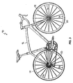
- Fig. 3 illustrates a bicycle having a wheel that includes an inner-tube embodying the present invention
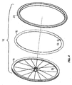
- Fig. 4 illustrates an enlarged exploded view of the wheel illustrated in Fig. 3;
- Fig. 5 is an exploded perspective view of a portion of the inner-tube illustrated in Fig. 4;
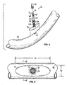
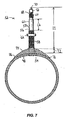
- Fig. 6 is an enlarged plane view of the valve assembly and a portion of the inner-tube illustrated in Fig. 5;
- Fig. 7 is a section view taken along line 7-7 of the inner-tube of Fig. 6.
- the bicycle 40 illustrated in Fig. 3 includes a frame 42 and two wheels 44, as is generally known in the art. As shown in Fig. 4, each of the wheels 44 includes a rim 46, an inner-tube 48 and a tire 50.
- the inner-tube 48 includes a valve assembly 52 that is positioned through a hole 53 in the rim 46 to facilitate access for inflation of the tire 50.
- the valve assembly 52 includes a valve housing 56.
- the valve housing 56 has an overall length L1 of about 50 millimeters. In other embodiments, the valve housing can have overall lengths L1 between about 30 millimeters to about 65 millimeters. The overall lengths L1 of the valve housing 56 can differ to correspond with the depth of the rim 46.
- the valve housing 56 includes a threaded lower portion 58 and an unthreaded upper portion 60.
- the unthreaded upper portion 60 has a length L2 of approximately about 13 millimeters. In other embodiments, the unthreaded upper portion 60 can have lengths L2 between about 5 millimeters and about 40 millimeters depending on the length L1 of the valve housing 56 and the depth of the rim 46.
- the absence of threading from the upper portion 60 of the valve housing 56 facilitates attachment of the pump head to a location of the valve housing 56 that is free from threads.
- the absence of threading from the upper portion 60 reduces the likelihood of damage to the pump head, and further reduces the force required to remove the pump head from the valve housing 56. Reducing the force required to remove the pump head from the valve housing 56 reduces the occurrence of the formation of holes in the inner-tube 48 in the area where the valve housing 56 attaches to the inner-tube 48.
- the threaded lower portion 58 is designed to receive a fastener 62 to secure the valve housing 56 to the rim 46. While the illustrated fastener 62 is a lock nut, it should be understood that the fastener 62 can include any suitable fastener.
- the illustrated valve housing 56 further includes a threaded tip 64 positioned adjacent to the upper portion 60. The threaded tip 60 is adapted to receive a valve cap 66 that inhibits the entry of dirt and moisture into the valve housing 56.
- the valve tip 64 has an external diameter smaller than the external diameter of the upper portion 60 of the valve housing 56 such that the threads of the tip 60 are not significantly engaged by the pump head during the inflating process.
- a valve core 68 is positioned within the valve housing 56 and is moveable between an open and a closed position. As is known in the art, the valve core 68 inhibits leakage of air from the inner-tube 48 when in the closed position, and allows entry of air into the inner-tube 48 when in the open position.
- the valve core 68 includes a stem 70 that extends from the interior of the housing 56 to the exterior of the housing 56, and a knurled lock nut 72 threaded onto the stem 70 in order to facilitate locking the valve core 68 in the closed position. While the illustrated valve assembly 52 includes the valve core 68 similar to the valve core of a Presta type valve, it should be understood that the valve assembly can include other suitable types of valve cores, such as the type of valve core used in a Schrader valve.
- a valve patch 74 is secured to the lower portion 58 of the valve housing 56 in order to facilitate attachment of the valve housing 56 to the inner-tube 48.
- the patch 74 is commonly made from a material, such as rubber, similar to or identical to the material of the inner-tube 48.
- a hole 54 is formed in the inner-tube 48, and the assembly of the patch 74 and housing 56 is positioned over the hole 54.
- the patch 74 is then secured to the exterior surface of the inner-tube 48 by any appropriate process such as vulcanization, adhesion, or chemical bonding.
- the illustrated patch 74 has a thickness T1 of approximately about 1.5 millimeters at a central portion, and the patch 74 is tapered to a thin edge 76 at its periphery. In other embodiments, the thickness T1 of the patch 74 can range from about 1 millimeter to about 2 millimeters.
- the patch 74 is dimensioned to have an aspect ratio (width divided by length) of less than about 0.35. More specifically, the illustrated patch 74 has a width W of about 16 millimeters and a length L3 of about 50 millimeters, resulting in an aspect ratio of about 0.32. In other embodiments, the patch can have an aspect ratio of less than about .50. While the mechanisms are not completely understood at this time, it has been found that reducing the aspect ratio of the patch 74 reduces the occurrence of the formation of holes in the inner-tube 48 in the area around the patch 74 and housing 56.
Applications Claiming Priority (2)
| Application Number | Priority Date | Filing Date | Title |
|---|---|---|---|
| US72868805P | 2005-10-19 | 2005-10-19 | |
| US11/334,225 US8122927B2 (en) | 2005-10-19 | 2006-01-18 | Inner-tube assembly for bicycle wheel |
Publications (3)
| Publication Number | Publication Date |
|---|---|
| EP1777080A2 true EP1777080A2 (de) | 2007-04-25 |
| EP1777080A3 EP1777080A3 (de) | 2007-05-30 |
| EP1777080B1 EP1777080B1 (de) | 2013-06-05 |
Family
ID=37622143
Family Applications (1)
| Application Number | Title | Priority Date | Filing Date |
|---|---|---|---|
| EP06021366.7A Active EP1777080B1 (de) | 2005-10-19 | 2006-10-11 | Schlauch für einen Fahrradreifen |
Country Status (3)
| Country | Link |
|---|---|
| US (1) | US8122927B2 (de) |
| EP (1) | EP1777080B1 (de) |
| TW (1) | TWI388440B (de) |
Families Citing this family (5)
| Publication number | Priority date | Publication date | Assignee | Title |
|---|---|---|---|---|
| JP4952647B2 (ja) * | 2008-04-30 | 2012-06-13 | 横浜ゴム株式会社 | タイヤ用チューブ |
| US8646477B2 (en) * | 2012-04-27 | 2014-02-11 | Yuan-Hung WEN | Structure of valve stem and frame lining |
| US20150298516A1 (en) * | 2014-02-18 | 2015-10-22 | Trek Bicycle Corp. | Pump head and valve stem assembly |
| ITUA20162810A1 (it) * | 2016-04-22 | 2017-10-22 | Barbieri S N C Di Barbieri Nadia E Kalman | Innesto e gruppo valvolare per pneumatici tubeless, e relativo procedimento di montaggio |
| US11560024B1 (en) | 2020-08-21 | 2023-01-24 | William Robert Hamilton, III | System, apparatus and method for adjusting air pressure in a tire |
Family Cites Families (31)
| Publication number | Priority date | Publication date | Assignee | Title |
|---|---|---|---|---|
| US483172A (en) * | 1892-09-27 | George h | ||
| US1313553A (en) * | 1919-08-19 | Fredekik nielsen | ||
| US589878A (en) * | 1897-09-14 | Fkiedeich veith | ||
| US634752A (en) * | 1898-03-25 | 1899-10-10 | Robert Honold | Bicycle-tire valve. |
| US928411A (en) * | 1908-05-25 | 1909-07-20 | Grace De Vigne | Valve for pneumatic tires. |
| US995961A (en) * | 1910-05-21 | 1911-06-20 | Shawmut Tire Company | Valve-base for pneumatic tires. |
| US1050942A (en) * | 1910-08-26 | 1913-01-21 | Cyrus A Haas | Check-valve for pneumatic tires. |
| US999506A (en) * | 1910-12-03 | 1911-08-01 | Morris Levrant | Air-tight valve for pneumatic tires. |
| US1395731A (en) * | 1919-10-20 | 1921-11-01 | Nathan F Rice | Valve-pad for pneumatic tires |
| US1456357A (en) * | 1921-11-12 | 1923-05-22 | Fisk Rubber Co | Valve pad for inner tubes and process of making same |
| US1479010A (en) * | 1922-10-16 | 1924-01-01 | Nathan F Rice | Valve pad for pneumatic tires |
| US1650502A (en) * | 1925-03-28 | 1927-11-22 | Erminio Guerci | Automobile tire valve for multiple air tubes |
| US1938816A (en) * | 1930-05-06 | 1933-12-12 | Morgan & Wright | Method and apparatus for uniting materials |
| US2018584A (en) | 1932-03-29 | 1935-10-22 | Watson Frank Hilliard | Valve stem |
| US1975415A (en) | 1932-11-21 | 1934-10-02 | Schraders Son Inc | Rubber headed valve stem |
| US2154254A (en) * | 1933-12-29 | 1939-04-11 | Schraders Son Inc | Valve stem |
| US2285008A (en) * | 1937-02-12 | 1942-06-02 | Dill Mfg Co | Valve stem |
| US2309061A (en) * | 1939-12-16 | 1943-01-19 | Ohio Injector Company | Inflation valve |
| CH231821A (de) | 1941-11-22 | 1944-04-15 | Hanko Ind Und Handelsgesellsch | Einrichtung zum Befestigen von Ventilen in Gummischläuchen. |
| US2731061A (en) * | 1953-11-17 | 1956-01-17 | Firestone Tire & Rubber Co | Valve |
| US3911988A (en) * | 1974-02-21 | 1975-10-14 | Eaton Corp | Pressurization control device |
| EP0349659A1 (de) | 1988-07-02 | 1990-01-10 | Dante Beretta | Universalschlauchanschlussstück für Fahrrad-, Motorrad-, und Kraftfahrzeugreifenventile |
| FR2705619A1 (fr) | 1993-05-26 | 1994-12-02 | Michelin & Cie | Valve de gonflage et procédé utilisant ladite valve pour gonflage d'un pneumatique avec anneau d'étanchéité. |
| US5433488A (en) | 1994-04-22 | 1995-07-18 | Chiago; Robert K. | Bicycle pump to Presta type valve adapter |
| US5558117A (en) | 1995-01-11 | 1996-09-24 | Mcguinness; Frank J. | Pneumatic valve assembly with dynamic annular seal flange |
| AP1017A (en) | 1995-02-03 | 2001-10-13 | Nvb Int | Valve connector. |
| US5762095A (en) * | 1996-04-22 | 1998-06-09 | Schwinn Cycling & Fitness Inc. | Combination pump head |
| US6120010A (en) | 1998-07-02 | 2000-09-19 | Schaffer; Brian J. | Air valve adapter |
| FR2787064B1 (fr) | 1998-12-14 | 2001-03-02 | Mavic Sa | Valve de gonflage pour une roue de bicyclette de type sans chambre a air |
| US6626501B2 (en) | 2000-01-19 | 2003-09-30 | Paul Davidoski | Positioning means for positioning the valve stem of an inner tube |
| EP1182061A3 (de) | 2000-08-22 | 2003-01-22 | Alligator Ventilfabrik GmbH | Reifenventil für die Felge eines Luftreifens an einem Fahrzeug |
-
2006
- 2006-01-18 US US11/334,225 patent/US8122927B2/en active Active
- 2006-03-16 TW TW095109008A patent/TWI388440B/zh active
- 2006-10-11 EP EP06021366.7A patent/EP1777080B1/de active Active
Non-Patent Citations (1)
| Title |
|---|
| None |
Also Published As
| Publication number | Publication date |
|---|---|
| TWI388440B (zh) | 2013-03-11 |
| US20070084536A1 (en) | 2007-04-19 |
| US8122927B2 (en) | 2012-02-28 |
| TW200716400A (en) | 2007-05-01 |
| EP1777080B1 (de) | 2013-06-05 |
| EP1777080A3 (de) | 2007-05-30 |
Similar Documents
| Publication | Publication Date | Title |
|---|---|---|
| JP4980621B2 (ja) | 取付パッチ構造及び空気入りタイヤ | |
| EP1777080B1 (de) | Schlauch für einen Fahrradreifen | |
| KR101137813B1 (ko) | 타이어 압력 모니터링 시스템 및 그의 타이어센서 | |
| US8245747B2 (en) | Tire valve and process for removing it | |
| US20080276995A1 (en) | Monitoring device attachment to rubber valve stems | |
| US20160001608A1 (en) | Sidewall decoration on rim guard | |
| US7775095B2 (en) | Valve stem with a connecting cap for a tire pressure detector | |
| CN110027364B (zh) | 自行车及轮胎结构 | |
| US20030192590A1 (en) | Valve stem adaptor | |
| US8038131B1 (en) | Air-cushion type shock-absorbing device for a wheeled vehicle | |
| US9701167B2 (en) | Snap-in valve for rubber wheels | |
| US11084234B2 (en) | Rapid repair of pneumatic tire with damage by cut or tear | |
| JP3173508U (ja) | チューブレスタイヤ用エアバルブ | |
| JP3973842B2 (ja) | チューブレスタイヤ用のワイヤースポークホイール | |
| JP2002240516A (ja) | 空気入りタイヤ | |
| US6568765B1 (en) | Composite wheel having a shallow rim | |
| US8109309B2 (en) | Tire with seats of unequal diameters and reverse axial offset in an inflated state | |
| JP4647369B2 (ja) | 空気入りタイヤ | |
| US3097682A (en) | Tire filler valve | |
| US20160152101A1 (en) | Tire Tool | |
| JP4457493B2 (ja) | タイヤ・ホイール組立体 | |
| US4258772A (en) | Air valve tightening construction for tire tube | |
| KR100529780B1 (ko) | 자동차용 공기입 타이어 | |
| JP2005082056A (ja) | 車両用ホイール | |
| JPS6027041Y2 (ja) | チユ−ブレスタイヤのビ−ド部脱落防止装置 |
Legal Events
| Date | Code | Title | Description |
|---|---|---|---|
| PUAI | Public reference made under article 153(3) epc to a published international application that has entered the european phase |
Free format text: ORIGINAL CODE: 0009012 |
|
| AK | Designated contracting states |
Kind code of ref document: A2 Designated state(s): AT BE BG CH CY CZ DE DK EE ES FI FR GB GR HU IE IS IT LI LT LU LV MC NL PL PT RO SE SI SK TR |
|
| AX | Request for extension of the european patent |
Extension state: AL BA HR MK YU |
|
| PUAL | Search report despatched |
Free format text: ORIGINAL CODE: 0009013 |
|
| AK | Designated contracting states |
Kind code of ref document: A3 Designated state(s): AT BE BG CH CY CZ DE DK EE ES FI FR GB GR HU IE IS IT LI LT LU LV MC NL PL PT RO SE SI SK TR |
|
| AX | Request for extension of the european patent |
Extension state: AL BA HR MK YU |
|
| RIC1 | Information provided on ipc code assigned before grant |
Ipc: B60C 5/04 20060101AFI20070129BHEP Ipc: B60C 29/04 20060101ALI20070423BHEP |
|
| 17P | Request for examination filed |
Effective date: 20070823 |
|
| AKX | Designation fees paid |
Designated state(s): DE GB IT |
|
| 17Q | First examination report despatched |
Effective date: 20121001 |
|
| GRAP | Despatch of communication of intention to grant a patent |
Free format text: ORIGINAL CODE: EPIDOSNIGR1 |
|
| GRAS | Grant fee paid |
Free format text: ORIGINAL CODE: EPIDOSNIGR3 |
|
| GRAA | (expected) grant |
Free format text: ORIGINAL CODE: 0009210 |
|
| AK | Designated contracting states |
Kind code of ref document: B1 Designated state(s): DE GB IT |
|
| REG | Reference to a national code |
Ref country code: GB Ref legal event code: FG4D |
|
| REG | Reference to a national code |
Ref country code: DE Ref legal event code: R096 Ref document number: 602006036632 Country of ref document: DE Effective date: 20130801 |
|
| PLBE | No opposition filed within time limit |
Free format text: ORIGINAL CODE: 0009261 |
|
| STAA | Information on the status of an ep patent application or granted ep patent |
Free format text: STATUS: NO OPPOSITION FILED WITHIN TIME LIMIT |
|
| 26N | No opposition filed |
Effective date: 20140306 |
|
| PG25 | Lapsed in a contracting state [announced via postgrant information from national office to epo] |
Ref country code: IT Free format text: LAPSE BECAUSE OF FAILURE TO SUBMIT A TRANSLATION OF THE DESCRIPTION OR TO PAY THE FEE WITHIN THE PRESCRIBED TIME-LIMIT Effective date: 20130605 |
|
| REG | Reference to a national code |
Ref country code: DE Ref legal event code: R097 Ref document number: 602006036632 Country of ref document: DE Effective date: 20140306 |
|
| GBPC | Gb: european patent ceased through non-payment of renewal fee |
Effective date: 20131011 |
|
| PG25 | Lapsed in a contracting state [announced via postgrant information from national office to epo] |
Ref country code: GB Free format text: LAPSE BECAUSE OF NON-PAYMENT OF DUE FEES Effective date: 20131011 |
|
| PGFP | Annual fee paid to national office [announced via postgrant information from national office to epo] |
Ref country code: DE Payment date: 20230830 Year of fee payment: 18 |