EP1776976B1 - Inhalationsgerätekompressor für eine Inhalationstherapievorrichtung - Google Patents
Inhalationsgerätekompressor für eine Inhalationstherapievorrichtung Download PDFInfo
- Publication number
- EP1776976B1 EP1776976B1 EP05022871A EP05022871A EP1776976B1 EP 1776976 B1 EP1776976 B1 EP 1776976B1 EP 05022871 A EP05022871 A EP 05022871A EP 05022871 A EP05022871 A EP 05022871A EP 1776976 B1 EP1776976 B1 EP 1776976B1
- Authority
- EP
- European Patent Office
- Prior art keywords
- compression device
- damping projections
- compressor according
- inhalation apparatus
- compressor
- Prior art date
- Legal status (The legal status is an assumption and is not a legal conclusion. Google has not performed a legal analysis and makes no representation as to the accuracy of the status listed.)
- Ceased
Links
- 238000002664 inhalation therapy Methods 0.000 title description 4
- 230000006835 compression Effects 0.000 claims description 59
- 238000007906 compression Methods 0.000 claims description 59
- 238000013016 damping Methods 0.000 claims description 43
- 239000000463 material Substances 0.000 claims description 5
- 229920002725 thermoplastic elastomer Polymers 0.000 claims description 4
- 229920002943 EPDM rubber Polymers 0.000 claims description 3
- 229920001296 polysiloxane Polymers 0.000 claims description 2
- 239000012858 resilient material Substances 0.000 claims 1
- 238000006073 displacement reaction Methods 0.000 description 16
- 230000035939 shock Effects 0.000 description 7
- 230000001133 acceleration Effects 0.000 description 2
- 230000015572 biosynthetic process Effects 0.000 description 2
- 230000000694 effects Effects 0.000 description 2
- 239000013013 elastic material Substances 0.000 description 2
- 238000003780 insertion Methods 0.000 description 2
- 230000037431 insertion Effects 0.000 description 2
- 239000006199 nebulizer Substances 0.000 description 2
- 239000002253 acid Substances 0.000 description 1
- 150000007513 acids Chemical class 0.000 description 1
- 230000032683 aging Effects 0.000 description 1
- 230000005484 gravity Effects 0.000 description 1
- 238000002663 nebulization Methods 0.000 description 1
- 238000002640 oxygen therapy Methods 0.000 description 1
- 229920002379 silicone rubber Polymers 0.000 description 1
- 239000000126 substance Substances 0.000 description 1
Images

Classifications
-
- A—HUMAN NECESSITIES
- A61—MEDICAL OR VETERINARY SCIENCE; HYGIENE
- A61M—DEVICES FOR INTRODUCING MEDIA INTO, OR ONTO, THE BODY; DEVICES FOR TRANSDUCING BODY MEDIA OR FOR TAKING MEDIA FROM THE BODY; DEVICES FOR PRODUCING OR ENDING SLEEP OR STUPOR
- A61M16/00—Devices for influencing the respiratory system of patients by gas treatment, e.g. ventilators; Tracheal tubes
- A61M16/0057—Pumps therefor
-
- A—HUMAN NECESSITIES
- A61—MEDICAL OR VETERINARY SCIENCE; HYGIENE
- A61M—DEVICES FOR INTRODUCING MEDIA INTO, OR ONTO, THE BODY; DEVICES FOR TRANSDUCING BODY MEDIA OR FOR TAKING MEDIA FROM THE BODY; DEVICES FOR PRODUCING OR ENDING SLEEP OR STUPOR
- A61M11/00—Sprayers or atomisers specially adapted for therapeutic purposes
- A61M11/02—Sprayers or atomisers specially adapted for therapeutic purposes operated by air or other gas pressure applied to the liquid or other product to be sprayed or atomised
-
- A—HUMAN NECESSITIES
- A61—MEDICAL OR VETERINARY SCIENCE; HYGIENE
- A61M—DEVICES FOR INTRODUCING MEDIA INTO, OR ONTO, THE BODY; DEVICES FOR TRANSDUCING BODY MEDIA OR FOR TAKING MEDIA FROM THE BODY; DEVICES FOR PRODUCING OR ENDING SLEEP OR STUPOR
- A61M15/00—Inhalators
-
- A—HUMAN NECESSITIES
- A61—MEDICAL OR VETERINARY SCIENCE; HYGIENE
- A61M—DEVICES FOR INTRODUCING MEDIA INTO, OR ONTO, THE BODY; DEVICES FOR TRANSDUCING BODY MEDIA OR FOR TAKING MEDIA FROM THE BODY; DEVICES FOR PRODUCING OR ENDING SLEEP OR STUPOR
- A61M16/00—Devices for influencing the respiratory system of patients by gas treatment, e.g. ventilators; Tracheal tubes
- A61M16/0057—Pumps therefor
- A61M16/0063—Compressors
-
- F—MECHANICAL ENGINEERING; LIGHTING; HEATING; WEAPONS; BLASTING
- F04—POSITIVE - DISPLACEMENT MACHINES FOR LIQUIDS; PUMPS FOR LIQUIDS OR ELASTIC FLUIDS
- F04B—POSITIVE-DISPLACEMENT MACHINES FOR LIQUIDS; PUMPS
- F04B39/00—Component parts, details, or accessories, of pumps or pumping systems specially adapted for elastic fluids, not otherwise provided for in, or of interest apart from, groups F04B25/00 - F04B37/00
- F04B39/0027—Pulsation and noise damping means
- F04B39/0044—Pulsation and noise damping means with vibration damping supports
-
- F—MECHANICAL ENGINEERING; LIGHTING; HEATING; WEAPONS; BLASTING
- F04—POSITIVE - DISPLACEMENT MACHINES FOR LIQUIDS; PUMPS FOR LIQUIDS OR ELASTIC FLUIDS
- F04B—POSITIVE-DISPLACEMENT MACHINES FOR LIQUIDS; PUMPS
- F04B39/00—Component parts, details, or accessories, of pumps or pumping systems specially adapted for elastic fluids, not otherwise provided for in, or of interest apart from, groups F04B25/00 - F04B37/00
- F04B39/14—Provisions for readily assembling or disassembling
-
- A—HUMAN NECESSITIES
- A61—MEDICAL OR VETERINARY SCIENCE; HYGIENE
- A61M—DEVICES FOR INTRODUCING MEDIA INTO, OR ONTO, THE BODY; DEVICES FOR TRANSDUCING BODY MEDIA OR FOR TAKING MEDIA FROM THE BODY; DEVICES FOR PRODUCING OR ENDING SLEEP OR STUPOR
- A61M11/00—Sprayers or atomisers specially adapted for therapeutic purposes
- A61M11/06—Sprayers or atomisers specially adapted for therapeutic purposes of the injector type
-
- A—HUMAN NECESSITIES
- A61—MEDICAL OR VETERINARY SCIENCE; HYGIENE
- A61M—DEVICES FOR INTRODUCING MEDIA INTO, OR ONTO, THE BODY; DEVICES FOR TRANSDUCING BODY MEDIA OR FOR TAKING MEDIA FROM THE BODY; DEVICES FOR PRODUCING OR ENDING SLEEP OR STUPOR
- A61M2205/00—General characteristics of the apparatus
- A61M2205/42—Reducing noise
Definitions
- the present invention relates to an inhalation device compressor for an inhalation therapy device, in particular for a compressed air-driven nozzle type inhalation therapy device.
- Nozzle nebulizers which generate the necessary for nebulization compressed air by means of a driven by an electric motor compressor.
- the compressor is usually operated at mains voltage; however, portable jet nebulizers use battery-powered compressors that are lighter in weight and therefore can be carried by the user, even during inhalation.
- the entrainment of the compressor often has a body contact result, in which make vibrations of the compressor unpleasant.
- the vibrations of the compressor can also lead to an undesirable noise.
- a relatively lightweight compressor can operate on shelf surfaces, such as a table top, when operated by self-vibration. Therefore, it is basically necessary to minimize the vibrations caused by the operation of the compressor.
- an object of the present invention is to provide an inhalation device compressor for an inhalation therapy device which is designed to attenuate both slight vibration vibration of an electric motor-driven compressor to a required degree and at the same time the driven by an electric motor compressor from damage protected by hard knocks and blows.
- an inhalation device compressor with an electric motor driven compression device and a housing with a receiving device for the compression device and a support member for supporting the compression device in the receiving device, which acts on the surface of the compression device and having a plurality of damping projections , each having such a non-linear force-displacement characteristic that the force / displacement ratio increases at a deflection of the compression device, wherein the support member encloses the compression means along at least a partial circumference attacking.
- the inhalation device compressor allows a secure seat of the compression device in a housing by a support member for supporting the compression device in the housing, wherein by the plurality of damping projections with a non-linear force-displacement characteristic is achieved that at a relatively low deflection, for example a vibration, the kinetic energy is absorbed in the damping projections, without being passed to the receiving device or the housing.
- a relatively low deflection for example a vibration
- the kinetic energy is absorbed in the damping projections, without being passed to the receiving device or the housing.
- the non-linear force-displacement characteristic that with harder shocks, the For example, occur in a fall of the inhaler compressor, relatively speaking, a lower deflection of the damping projections occurs.
- the negative acceleration experienced by the compression device is substantially less than the negative acceleration experienced by the housing.
- the inhaler compressor according to the invention is both able to dampen operational vibration for a more comfortable operation as well as to absorb hard shock in consequence of, for example, a fall and thus to protect a compression device from damage.
- the support element engaging the compressing device along at least part of its circumference permits, in addition to the damping properties for vibrations and hard impacts, positioning of the compression device, since the partial enclosure prevents a tangential displacement.
- the damping projections have extension axes, which are aligned substantially perpendicular to the surface of the compression device.
- the force usually takes place in the direction of the center of gravity, which is in a compression device in its interior.
- the force effect in a shock occurs substantially perpendicular to at least a surface portion of the compression device.
- the damping projections are thus loaded in the direction of their extension axis, so that their force-displacement curve can be adjusted correspondingly well to be able to fulfill the function of damping a hard shock well.
- the damping projections taper in a region along the extension axis in the direction of the surface of the compression device.
- the strongest deformation takes place at the most tapered areas, which advantageously abut against the surface of the compression means.
- the non-linear force-displacement characteristic is achieved by a geometric formation of the bulge.
- the support member can be made of a homogeneous material, since the non-linear force-displacement characteristic is achieved by the geometric shape.
- the most tapered regions of the damping projections are designed such that they engage the compression device.
- Such formation of the damper protrusions allows easy assembly because the damper protrusions are easiest to deform at their most tapered portion, thereby allowing easy insertion of the compression mechanism into or onto the support member.
- the damping projections are deformable in the direction of the extension axis. In this way, a recording of the kinetic energy in a movement of the compression device relative to the housing is possible.
- the damping projections are made essentially of elastic materials, preferably of one of the materials silicone, EPDM or TPE. These materials have high elasticity, chemical resistance to acids and alkalis, ease of processing and aging resistance.
- the damping projections are arranged side by side such that they are designed substantially in the form of a shaft in the direction of the circumference or partial circumference of the compression device.
- the non-linear force-displacement characteristic of the damping projections can be easily reconciled with a space-saving arrangement of the damping projections next to each other.
- wear or tearing of the support element can additionally be avoided.
- the holding elements comprise the compression device along a circumference substantially completely attacking.
- an improved positioning of the compression device can be effected in the receiving device, in which a damping in each direction can be achieved and a uniform loading of the support member occurs.
- the support member is formed integrally with a substantially circular opening and has in the opening inwardly directed damping projections.
- a support member allows a recording of the compression device such that the elasticity of the support member prevents slipping of the compression device and a loss of the support member can be avoided.
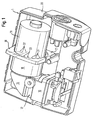
- FIG. 1 shows an embodiment of an inhalation device compressor according to the invention 1.
- the inhaler compressor 1 comprises a housing 20, of which in FIG. 1 only a lower shell is shown and in which a means of electric motor 11 driven compression device 10 is to provide compressed air for an inhalation nebulizer not shown here with nebulizer.
- the housing has a receiving device 21 to receive the compression device 10. Also of the receiving device 21 is only the part in FIG. 1 shown, which is arranged in the illustrated housing shell 20.
- the compression device 10 is not directly brought into contact with the receiving device 21, but held by means of a support member 30 in the receiving device 21.
- a support member 30 in the receiving device 21 As a housing shell in FIG. 1 is not shown, the projecting from the receiving device 21 outstanding part of the support member 30 is easy to see.
- the support member 30 engages the surface of the compression device 10 and has a plurality of damping projections 31, each having a non-linear force-displacement characteristic, so that the force / displacement ratio at a deflection of the compression device 10 increases from the rest position.
- the support member 30 engages the outer circumference of the electric motor 11 associated with the compression device 10.
- the holding element can also act on a planar surface of the compression device 10.
- FIG. 2 shows the embodiment of an inhalation device according to the invention according to compressor FIG. 1 However, for improved visibility without the means of electric motor 11 driven compression device 10. From the representation of the figure results in the possible position and position of the support members 30 for supporting the compression device 10th
- the support element designated by the reference numeral 30 engages an approximately circular periphery of an electric motor 11 belonging to the compression device 10 and comprises this approximately at its half circumference.
- a corresponding counterpart of a receiving device 21 and a support member 30 is in the in the FIGS. 1 and 2 Not shown part of the housing 20 is provided so that the provided in the housing 20 support member and provided in the cover of the housing support member 30 include the electric motor 11 almost completely.
- an embodiment is conceivable in which only a part of the circumference, for example, of the electric motor is supported, and the support members 30 attack only on sub-peripheries of belonging to the compression device 10 electric motor 11.
- a support member 30 is possible, which is made in one piece and internally has a substantially circular opening into which the damping projections 31 extend, so that, for example, an electric motor is first introduced into this opening, to then together with the support member 30 in the housing 20 to be placed.
- the damping projections 31 taper along their extension axes and, in the embodiment shown here, engage with the most tapered regions 33 on the compression device 10.
- the damping projections 31 are deformable in the direction of their extension axes 32, so that they can absorb a kinetic energy produced by a vibration or a shock and convert them into, for example, heat or kinetic energy.
- the non-linear force-displacement characteristic which leads to an increasing force / displacement ratio with a deflection of the compression device 10 with respect to the housing 20 and the receiving device 21, can be achieved solely by the geometric configuration in the form of the tapered damping projections 31 be brought about. In this way it is possible to absorb both smaller deflections in an operational vibration of the compression device 10 and to absorb the forces occurring in a shock or a fall.
- the deflection occurring with a relatively small force as a result of a vibration is absolutely lower, but relatively higher than a deflection that occurs as a result of a hard impact or a fall.
- the damping projections are advantageously made of elastic materials such as silicone, Ethylenpropylendimerisaten (EPDM) or thermoplastic elastomers (TPE). But there are others besides suitable materials conceivable that have an elastic property.
- EPDM Ethylenpropylendimerisaten
- TPE thermoplastic elastomers
- the holding element 30 may have different configurations, for example in the form of a retaining element acting on an outer circumference of, for example, a cylinder, wherein the cylinder does not necessarily have to be a circular cylinder but, for example, may also have an oval, square, rectangular or other cross-section.
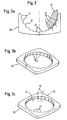
- FIG. 3 shows a more detailed view of a support member 30 which is formed so that it engages at least on a partial circumference of the compression device 10.
- FIG. 3a shows a sectional view of a support member in which the damping projections 31 extend along an extension axis 32, wherein the extension axes 32 is substantially perpendicular to the surface of the compression device 10.
- the damping projections 31 thereby taper along their extension axes 32 in the direction of the surface of the compression device 10.
- the most tapered regions 33 of the damping projections 31 are designed such that they engage the compression device 10.
- FIG. 3b shows two assembled support members 30, which may be provided, for example, when a compression device 10 is to be supported by two respectively provided in a housing part support members 30.
- Figure 3c shows a support member integrally provided with a substantially circular opening 34 is, in which the damping projections 31 are designed directed inwards.
- a mounting device 30 is preferably attached to the compression device 10 prior to insertion into an inhalation device compressor, to be disposed together with it in the receptacle or receptacles of the housing of the inhalation device compressor.
- the damping projections 31 are preferably arranged next to each other in the support element 30, so that their surface facing the compression device is configured essentially in the form of a shaft.
- a wave may, for example, have substantially the form of a sine wave, but a waveform is also conceivable which repeats periodically in the form of a triangle or sawtooth or a trapezoidal shape, so that the individual damping projection 31 is in the form of a triangle, a sine wave or a Trapezes may have, each having a non-linear force-displacement characteristic due to their geometry.
- the support surface of the damping projections 31 is small in vibration relative to a bearing surface of the surface of the compression device 10 in a hard impact or fall. This is due to the higher force effect that occurs in a fall or a hard impact compared to a vibration.
- the bearing surface does not increase linearly with the force due to the non-linear force-displacement characteristic.
Landscapes
- Health & Medical Sciences (AREA)
- Engineering & Computer Science (AREA)
- Life Sciences & Earth Sciences (AREA)
- Animal Behavior & Ethology (AREA)
- Anesthesiology (AREA)
- Biomedical Technology (AREA)
- Heart & Thoracic Surgery (AREA)
- Hematology (AREA)
- Veterinary Medicine (AREA)
- Public Health (AREA)
- General Health & Medical Sciences (AREA)
- Pulmonology (AREA)
- Emergency Medicine (AREA)
- Mechanical Engineering (AREA)
- General Engineering & Computer Science (AREA)
- Bioinformatics & Cheminformatics (AREA)
- Compressor (AREA)
Description
- Die vorliegende Erfindung betrifft einen Inhalationsgerätekompressor für eine Inhalationstherapievorrichtung, insbesondere für eine Inhalationstherapievorrichtung vom druckluftbetriebenen Düsentyp.
- Im Stand der Technik, zum Beispiel aus
EP 0 712 636 , sind Düsenvernebler bekannt, die die für die Vernebelung notwendige Druckluft mit Hilfe eines durch einen Elektromotor angetriebenen Kompressors erzeugen. Der Kompressor wird in der Regel an Netzspannung betrieben; jedoch verwenden tragbare Düsenvernebler batteriebetriebene Kompressoren, die leichter sind und deshalb vom Benutzer, auch während einer Inhalation, mitgeführt werden können. Das Mitführen des Kompressors hat häufig einen Körperkontakt zur Folge, bei dem sich Vibrationen des Kompressors unangenehm bemerkbar machen. Die Vibrationen des Kompressors können auch zu einer unerwünschten Geräuschentwicklung führen. Ferner kann ein verhältnismäßig leichter Kompressor bei einem Betrieb durch die Eigenvibration auf Ablageflächen, beispielsweise einer Tischplatte, in Bewegung geraten. Daher ist es grundsätzlich notwendig, die durch den Betrieb des Kompressors hervorgerufenen Vibrationen zu minimieren. - Andererseits ist bei tragbaren Kompressoren das Risiko erhöht, dass der Kompressor bei einem Transport beschädigt wird, beispielsweise durch einen Sturz auf den Boden. Daher ist es ebenso notwendig, den Kompressor und dessen Komponenten vor harten Schlägen und Stößen zu schützen.
- Im Bereich der Sauerstofftherapiegeräte ist aus
WO2005/035037A2 bekannt, das Gehäuse eines auf einem Transportwagen bewegbaren Geräts so auszugestalten, dass ein Kompressor auf einer oberen Oberfläche einer Kompressorhalterung ruht, die sich von einer Basis des Gehäuses nach oben erstreckt. Dabei ragt ein Antriebsmotor des Kompressors in eine Öffnung der Kompressorhalterung hinein. Zur Halterung des Kompressors sind aber Kompressorhaltereinrichtungen vorgesehen, die zwischen dem Kompressor und dem Gehäuse angeordnet sind. Diese Halteeinrichtungen sind als Spannfedern beschrieben, durch die der Kompressor in seiner Position gehaltert wird. - Vor diesem Hintergrund besteht eine Aufgabe der vorliegenden Erfindung darin, einen Inhalationsgerätekompressor für eine Inhalationstherapievorrichtung bereitzustellen, der dafür ausgelegt ist, sowohl leichte Vibrationsschwingungen eines durch einen Elektromotor angetriebenen Kompressors auf ein erforderliches Maß zu dämpfen als auch gleichzeitig den durch einen Elektromotor angetriebenen Kompressor vor einer Beschädigung durch harte Stöße und Schläge zu schützen.
- Die Aufgabe der vorliegenden Erfindung wird gelöst durch einen Inhalationsgerätekompressor mit einer mittels Elektromotor angetriebenen Kompressionseinrichtung und einem Gehäuse mit einer Aufnahmeeinrichtung für die Kompressionseinrichtung und einem Halterungselement zum Haltern der Kompressionseinrichtung in der Aufnahmeeinrichtung, das an der Oberfläche der Kompressionseinrichtung angreift und das eine Mehrzahl von Dämpfungsvorsprüngen aufweist, die jeweils eine derart nicht-lineare Kraft-Weg-Kennlinie aufweisen, dass das Kraft/Weg-Verhältnis bei einer Auslenkung der Kompressionseinrichtung zunimmt, wobei das Halterungselement die Kompressionseinrichtung entlang wenigstens eines Teilumfangs angreifend umschließt.
- Der erfindungsgemäße Inhalationsgerätekompressor erlaubt durch ein Halterungselement zum Haltern der Kompressionseinrichtung in der Aufnahmeeinrichtung einen sicheren Sitz der Kompressionseinrichtung in einem Gehäuse, wobei durch die Mehrzahl von Dämpfungsvorsprüngen mit einer nicht-linearen Kraft-Weg-Kennlinie erreicht wird, dass bei einer verhältnismäßig geringen Auslenkung, beispielsweise einer Vibration, die Bewegungsenergie in den Dämpfungsvorsprüngen aufgefangen wird, ohne an die Aufnahmeeinrichtung bzw. das Gehäuse weitergegeben zu werden. Auf der anderen Seite wird durch die nicht-lineare Kraft-Weg-Kennlinie erreicht, dass bei härteren Stößen, die beispielsweise bei einem Herunterfallen des Inhalationsgerätekompressors auftreten, relativ gesehen eine geringere Auslenkung der Dämpfungsvorsprünge auftritt. So ist bei einem harten Stoß die negative Beschleunigung, die die Kompressionseinrichtung erfährt, wesentlich geringer als die negative Beschleunigung, die das Gehäuse erfährt. Auf diese Weise ist der erfindungsgemäße Inhalationsgerätekompressor sowohl in der Lage betriebsbedingte Vibrationen für einen komfortableren Betrieb abzudämpfen als auch harte Stöße in Folge beispielsweise eines Sturzes aufzufangen und somit eine Kompressionseinrichtung vor einer Beschädigung zu schützen. Das die Kompressionseinrichtung entlang wenigstens eines Teilumfanges umschließend angreifende Halterungselement erlaubt neben den Dämpfungseigenschaften für Vibrationen und harte Stöße auch eine Positionierung der Kompressionseinrichtung, da die teilweise Umschließung eine tangentiale Verschiebung unterbindet.
- Gemäß einer vorteilhaften Ausführungsform weisen die Dämpfungsvorsprünge Erstreckungsachsen auf, die im wesentlichen senkrecht zur Oberfläche der Kompressionseinrichtung ausgerichtet sind. Bei einem Stoß oder einem Sturz erfolgt die Kraftwirkung in der Regel in Richtung des Schwerpunktes, der sich bei einer Kompressionseinrichtung in ihrem Inneren befindet. Die Kraftwirkung bei einem Stoß erfolgt im wesentlichen senkrecht zu wenigstens einem Oberflächenteil der Kompressionseinrichtung. Die Dämpfungsvorsprünge werden somit in Richtung ihrer Erstreckungsachse belastet, so dass ihre Kraft-Weg-Kennlinie entsprechend gut eingestellt werden kann, um die Funktion der Abdämpfung eines harten Stoßes gut erfüllen zu können.
- Gemäß einer weiteren vorteilhaften Ausführungsform verjüngen sich die Dämpfungsvorsprünge in einem Bereich entlang der Erstreckungsachse in Richtung der Oberfläche der Kompressionseinrichtung. Bei einer geringen Auslenkung der Kompressionseinrichtung, beispielsweise aufgrund von Vibration, erfolgt die stärkste Verformung an den am stärksten verjüngten Bereichen, die vorteilhafterweise an der Oberfläche der Kompressionseinrichtung anliegen. Durch die Verjüngung der Dämpfungsvorsprünge entlang der Erstreckungsachse in Richtung der Oberfläche wird die nicht-lineare Kraft-Weg-Kennlinie durch eine geometrische Ausformung der Auswölbung erreicht. Vorteilhafterweise kann dadurch das Halterungselement aus einem homogenen Material gefertigt werden, da die nicht-lineare Kraft-Weg-Kennlinie durch die geometrische Ausformung erreicht wird.
- Gemäß einer weiteren vorteilhaften Ausführungsform sind die am meisten verjüngten Bereiche der Dämpfungsvorsprünge derart ausgelegt, dass sie an der Kompressionseinrichtung angreifen. Eine derartige Ausformung der Dämpfungsvorsprünge erlaubt eine leichte Montage, da sich die Dämpfungsvorsprünge an ihrem am meisten verjüngten Bereich am leichtesten verformen lassen, wodurch ein einfaches Einführen der Kompressionseinrichtung in oder an das Halterungselement ermöglicht wird.
- Gemäß einer weiteren vorteilhaften Ausführungsform sind die Dämpfungsvorsprünge in Richtung der Erstreckungsachse verformbar ausgebildet. Auf diese Weise ist eine Aufnahme der Bewegungsenergie bei einer Bewegung der Kompressionseinrichtung gegenüber dem Gehäuse möglich.
- Gemäß einer weiteren vorteilhaften Ausführungsform sind die Dämpfungsvorsprünge im wesentlichen aus elastischen Materialien, vorzugsweise aus einem der Materialien Silikon, EPDM oder TPE gefertigt. Diese Materialien weisen eine hohe Elastizität, eine chemische Widerstandsfähigkeit gegenüber Säuren und Laugen, eine einfache Verarbeitbarkeit und eine gute Alterungsbeständigkeit auf.
- Gemäß einer weiteren vorteilhaften Ausführungsform sind die Dämpfungsvorsprünge derart nebeneinander angeordnet, dass sie im wesentlichen in Form einer Welle in Richtung des Umfangs bzw. Teilumfangs der Kompressionseinrichtung ausgestaltet sind. Auf diese Weise lässt sich die nicht-lineare Kraft-Weg-Kennlinie der Dämpfungsvorsprünge mit einer platzsparenden Anordnung der Dämpfungsvorsprünge nebeneinander gut vereinbaren. Bei einer Ausgestaltung in Form einer Welle ohne scharfen Kanten oder Kerben kann zusätzlich ein Verschleißen oder Einreißen des Halterungselementes vermieden werden.
- Gemäß einer weiteren vorteilhaften Ausführungsform umfassen die Halterungselemente die Kompressionseinrichtung entlang eines Umfangs im wesentlichen vollständig angreifend. Auf diese Weise kann eine verbesserte Positionierung der Kompressionseinrichtung in der Aufnahmeeinrichtung bewirkt werden, bei der eine Dämpfung in jede Richtung erreicht werden kann und eine gleichmäßige Beanspruchung des Halterungselementes auftritt.
- Gemäß einer weiteren vorteilhaften Ausführungsform ist das Halterungselement einstückig mit einer im wesentlichen kreisförmigen Öffnung ausgeführt und weist in der Öffnung nach innen gerichtete Dämpfungsvorsprünge auf. Ein derartiges Halterungselement erlaubt eine Aufnahme der Kompressionseinrichtung derart, dass die Elastizität des Halterungselementes ein Abrutschen von der Kompressionseinrichtung verhindert und ein Verlorengehen des Halterungselementes vermieden werden kann.
- Die nachfolgenden Figuren zeigen vorteilhafte Ausgestaltungen des erfindungsgemäßen Inhalationsgerätekompressors; im Einzelnen zeigt:
- Figur 1
- einen Inhalationsgerätekompressor gemäß der vorliegenden Erfindung;
- Figur 2
- einen Inhalationsgerätekompressor der vorliegenden Erfindung, bei dem die Kompressionseinrichtung entnommen ist und;
- Figur 3a bis 3c
- eine Ausführungsform eines Halterungselementes, das in dem erfindungsgemäßen Inhalationsgerätekompressor verwendet wird.
-
Figur 1 zeigt ein Ausführungsbeispiel eines erfindungsgemäßen Inhalationsgerätekompressors 1. Der Inhalationsgerätekompressor 1 weist ein Gehäuse 20 auf, von dem inFigur 1 nur eine untere Schale gezeigt ist und in dem sich eine mittels Elektromotor 11 angetriebene Kompressionseinrichtung 10 befindet, um für einen hier nicht gezeigten Inhalationsvernebler mit Verneblerdüse Druckluft bereit zu stellen. Das Gehäuse weist eine Aufnahmeeinrichtung 21 auf, um die Kompressionseinrichtung 10 aufzunehmen. Auch von der Aufnahmeeinrichtung 21 ist nur der Teil inFigur 1 gezeigt, der in der dargestellten Gehäuseschale 20 angeordnet ist. - Erfindungsgemäß wird die Kompressionseinrichtung 10 nicht unmittelbar mit der Aufnahmeeinrichtung 21 in Kontakt gebracht, sondern mittels eines Halterungselementes 30 in der Aufnahmeeinrichtung 21 gehaltert. Da eine Gehäuseschale in
Figur 1 nicht gezeigt ist, ist das aus der gezeigten Aufnahmeeinrichtung 21 herausragende Teil des Halterungselements 30 gut zu erkennen. - Das Halterungselement 30 greift an der Oberfläche der Kompressionseinrichtung 10 an und weist eine Mehrzahl von Dämpfungsvorsprüngen 31 auf, die jeweils eine nicht-lineare Kraft-Weg-Kennlinie aufweisen, so dass das Kraft/Weg-Verhältnis bei einer Auslenkung der Kompressionseinrichtung 10 aus der Ruhelage zunimmt. Das Halterungselement 30 greift an dem äußeren Umfang des zu der Kompressionseinrichtung 10 gehörenden Elektromotors 11 an. Alternativ kann das Haltungselement auch an einer planen Oberfläche der Kompressionseinrichtung 10 angreifen.
-
Figur 2 zeigt das Ausführungsbeispiel eines erfindungsgemäßen Inhalationsgerätekompressors gemäßFigur 1 , jedoch für eine verbesserte Erkennbarkeit ohne die mittels Elektromotor 11 angetriebene Kompressionseinrichtung 10. Aus der Darstellung der Figur ergibt sich die mögliche Lage und Position der Halterungselemente 30 zum Haltern der Kompressionseinrichtung 10. - In der gezeigten Ausführungsform greift das mit der Bezugsziffer 30 bezeichnete Halterungselement an einem annähernd kreisförmigen Umfang eines zu der Kompressionseinrichtung 10 gehörigen Elektromotors 11 an und umfasst diesen etwa an seinem halben Umfang. Ein entsprechendes Gegenstück einer Aufnahmeeinrichtung 21 und eines Halterungselementes 30 ist in dem in den
Figuren 1 und2 nicht gezeigten Teil des Gehäuses 20 vorgesehen, so dass das in dem Gehäuse 20 vorgesehene Halterungselement und das in dem Deckel des Gehäuses vorgesehene Halterungselement 30 den Elektromotor 11 nahezu vollständig umfassen. Alternativ ist jedoch auch eine Ausführungsform denkbar, bei der nur ein Teilumfang beispielsweise des Elektromotors gehaltert wird, und die Halterungselemente 30 nur an Teilumfängen des zu der Kompressionseinrichtung 10 gehörigen Elektromotors 11 angreifen. Ferner ist ein Halterungselement 30 möglich, das einstückig ausgeführt ist und im Inneren eine im wesentlichen kreisförmige Öffnung aufweist, in die sich die Dämpfungsvorsprünge 31 hinein erstrecken, so dass beispielsweise ein Elektromotor in diese Öffnung zunächst eingeführt wird, um dann zusammen mit dem Halterungselement 30 in dem Gehäuse 20 platziert zu werden. - Die Dämpfungsvorsprünge 31 verjüngen sich entlang ihrer Erstreckungsachsen und greifen in der hier gezeigten Ausführungsform mit den am meisten verjüngten Bereichen 33 an der Kompressionseinrichtung 10 an. Die Dämpfungsvorsprünge 31 sind in Richtung ihrer Erstreckungsachsen 32 verformbar ausgebildet, so dass sie eine durch eine Vibration oder einen Stoß entstehende Bewegungsenergie aufnehmen können und diese beispielsweise in Wärme oder in kinetische Energie umwandeln.
- Die nicht-lineare Kraft-Weg-Kennlinie, die zu einem zunehmenden Kraft/Weg- Verhältnis bei einer Auslenkung der Kompressionseinrichtung 10 in Bezug auf das Gehäuse 20 bzw. die Aufnahmeeinrichtung 21 ausführt, kann allein durch die geometrische Ausgestaltung in Form der verjüngenden Dämpfungsvorsprünge 31 herbeigeführt werden. Auf diese Weise ist es möglich, sowohl kleinere Auslenkungen bei einer betriebsbedingten Vibration der Kompressionseinrichtung 10 aufzunehmen als auch die bei einem Stoß oder einem Sturz auftretenden Kräfte aufzunehmen. Die bei einer verhältnismäßig geringen Krafteinwirkung infolge einer Vibration auftretende Auslenkung ist absolut zwar geringer, jedoch relativ gesehen höher als eine Auslenkung, die infolge eines harten Stoßes oder eines Sturzes auftritt. Dies ist im wesentliche darauf zurückzuführen, dass sich bei einer zunehmenden Auslenkung zunächst die am meisten verjüngten Bereiche der Dämpfungsvorsprünge stärker verformen, wobei sich die breiteren Bereiche der Dämpfungsvorsprünge erst bei einer größeren Krafteinwirkung stärker verformen. Auf diese Weise kann durch die geometrische Ausformung der Dämpfungsvorsprünge eine nicht lineare Kraft-Weg-Kennlinie erreicht werden.
- Die Dämpfungsvorsprünge bestehen vorteilhafterweise aus elastischen Materialien wie Silikon, Ethylenpropylendimerisaten (EPDM) oder thermoplastischen Elastomeren (TPE). Es sind jedoch darüber hinaus noch andere geeignete Materialien denkbar, die eine elastische Eigenschaft aufweisen.
- Je nach Verwendung kann das Halterungselement 30 unterschiedliche Ausgestaltung aufweisen, beispielsweise in Form eines an einem äußeren Umfang beispielsweise eines Zylinders angreifenden Halterungselements, wobei der Zylinder nicht notwendigerweise ein Kreiszylinder sein muss, sondern beispielsweise auch einen ovalen, quadratischen, rechteckigen oder andersförmigen Querschnitt aufweisen kann.
-
Figur 3 zeigt eine detailliertere Ansicht eines Halterungselementes 30, das derart ausgebildet ist, dass es zumindest an einem Teilumfang der Kompressionseinrichtung 10 angreift. -
Figur 3a zeigt eine Schnittansicht eines Halterungselementes, bei dem sich die Dämpfungsvorsprünge 31 entlang einer Erstreckungsachse 32 erstrecken, wobei sich die Erstreckungsachsen 32 im wesentlichen senkrecht zur Oberfläche der Kompressionseinrichtung 10 befindet. - Die Dämpfungsvorsprünge 31 verjüngen sich dabei entlang ihrer Erstreckungsachsen 32 in Richtung der Oberfläche der Kompressionseinrichtung 10. Dabei sind die am meisten verjüngten Bereiche 33 der Dämpfungsvorsprünge 31 so ausgelegt, dass sie an der Kompressionseinrichtung 10 angreifen.
-
Figur 3b zeigt zwei zusammengefügte Halterungselemente 30, die beispielsweise vorgesehen werden können, wenn eine Kompressionseinrichtung 10 durch zwei jeweils in einem Gehäuseteil vorgesehene Halterungselemente 30 gehaltert werden soll. -
Figur 3c zeigt ein Halterungselement, das einstückig mit einer im wesentlichen kreisförmigen Öffnung 34 vorgesehen ist, bei dem die Dämpfungsvorsprünge 31 nach innen gerichtet ausgestaltet sind. Eine derartige Halterungseinrichtung 30 wird vorzugsweise vor einem Einbringen in einem Inhalationsgerätekompressor an der Kompressionsvorrichtung 10 angebracht, um dann gemeinsam mit dieser in der Aufnahme bzw. den Aufnahmen des Gehäuses des Inhalationsgerätekompressors angeordnet zu werden. - Die Dämpfungsvorsprünge 31 sind in dem Halterungselement 30 vorzugsweise nebeneinander angeordnet, so dass ihre der Kompressionseinrichtung zugewandten Oberfläche im wesentlichen in Form einer Welle ausgestaltet sind. Eine derartige Welle kann beispielsweise im wesentlichen die Form einer Sinuswelle aufweisen, jedoch ist auch eine Wellenform denkbar, die sich in Form eines Dreiecks oder Sägezahns bzw. einer Trapezform periodisch wiederholt, so dass der einzelne Dämpfungsvorsprung 31 die Form eines Dreiecks, einer Sinuswelle oder eines Trapezes aufweisen kann, die jeweils aufgrund ihrer Geometrie eine nicht-lineare Kraft-Weg-Kennlinie aufweisen. Ferner ist es möglich einen Dämpfungsvorsprung 31 derart auszuformen, dass er die Form einer Pyramide, einer Kuppel oder eines Kegels bzw. Kegelstumpfes aufweist.
- In dem in
Figur 3 gezeigten Halterungselement 30 ist die Auflagefläche der Dämpfungsvorsprünge 31 bei einer Vibration klein im Verhältnis zu einer Auflagefläche der Oberfläche der Kompressionseinrichtung 10 bei einem harten Stoß bzw. Sturz. Dies ist auf die höhere Kraftwirkung zurückzuführen, die bei einem Sturz bzw. einem harten Stoß im Vergleich zu einer Vibration auftritt. Die Auflagefläche nimmt dabei jedoch aufgrund der nicht linearen Kraft-Weg-Kennlinie nicht linear mit der Kraft zu.
Claims (9)
- Inhalationsgerätekompressor mit- einer mittels Elektromotor (11) angetriebenen Kompressionseinrichtung (10) und- einem Gehäuse (20) mit- einer Aufnahmeeinrichtung (21) für eine Kompressionseinrichtung (10) und- einem Halterungselement (30) zum Haltern der Kompressionseinrichtung (10) in der Aufnahmeeinrichtung (21),wobei das Halterungselement (30) die Kompressionseinrichtung (10) entlang wenigstens eines Teilumfangs angreifend umschließt.o das an der Oberfläche der Kompressionseinrichtung (10) angreift undo das eine Mehrzahl von Dämpfungsvorsprüngen (31) aufweist, die jeweils eine derart nichtlineare Kraft-Weg-Kennlinie aufweisen, dass das Kraft/Weg-Verhältnis bei einer Auslenkung der Kompressionseinrichtung (10) zunimmt,
- Inhalationsgerätekompressor gemäß Anspruch 1, dadurch gekennzeichnet, dass die Dämpfungsvorsprünge (31) Erstreckungsachsen (32) aufweisen, die im wesentlichen senkrecht zur Oberfläche der Kompressionseinrichtung (10) ausgerichtet sind.
- Inhalationsgerätekompressor gemäß einem der vorangegangenen Ansprüche, dadurch gekennzeichnet, dass sich die Dämpfungsvorsprünge (31) in einem Bereich entlang ihrer Erstreckungsachse (32) in Richtung der Oberfläche der Kompressionseinrichtung (10) verjüngen.
- Inhalationsgerätekompressor gemäß einem der vorangegangenen Ansprüche, dadurch gekennzeichnet, dass die am meisten verjüngten Bereiche (33) der Dämpfungsvorsprünge (31) ausgelegt sind, an der Kompressionseinrichtung (10) anzugreifen.
- Inhalationsgerätekompressör gemäß einem der vorangegangenen Ansprüche, dadurch gekennzeichnet, dass die Dämpfungsvorsprünge (31) in Richtung ihrer Erstreckungsachse (32) verformbar ausgebildet sind.
- Inhalationsgerätekompressor gemäß einem der vorangegangenen Ansprüche, dadurch gekennzeichnet, dass die Dämpfungsvorsprünge (31) im wesentlichen aus einem elastischen Material, vorzugsweise einem der Materialen Silikon, EPDM oder TPE bestehen.
- Inhalationsgerätekompressor gemäß einem der vorangegangenen Ansprüche, dadurch gekennzeichnet, dass die Dämpfungsvorsprünge (31) derart nebeneinander angeordnet sind, dass sie im wesentlichen in Form einer Welle in Richtung des Umfangs bzw. Teilumfangs der Kompressionseinrichtung (10) ausgestaltet sind.
- Inhalationsgerätekompressor gemäß einem der vorangegangenen Ansprüche, dadurch gekennzeichnet, dass das Halterungselement (30) die Kompressionseinrichtung (10) entlang eines Umfanges im wesentlichen vollständig angreifend umfasst.
- Inhalationsgerätekompressor gemäß einem der vorangegangenen Ansprüche, dadurch gekennzeichnet, dass das Halterungselement (30) einstückig mit einer im wesentlichen kreisförmigen Öffnung (34) und mit in der Öffnung (34) angeordneten und nach innen gerichteten Dämpfungsvorsprüngen (31) ausgestaltet ist.
Priority Applications (1)
| Application Number | Priority Date | Filing Date | Title |
|---|---|---|---|
| EP05022871A EP1776976B8 (de) | 2005-10-20 | 2005-10-20 | Inhalationsgerätekompressor für eine Inhalationstherapievorrichtung |
Applications Claiming Priority (1)
| Application Number | Priority Date | Filing Date | Title |
|---|---|---|---|
| EP05022871A EP1776976B8 (de) | 2005-10-20 | 2005-10-20 | Inhalationsgerätekompressor für eine Inhalationstherapievorrichtung |
Publications (3)
| Publication Number | Publication Date |
|---|---|
| EP1776976A1 EP1776976A1 (de) | 2007-04-25 |
| EP1776976B1 true EP1776976B1 (de) | 2011-12-14 |
| EP1776976B8 EP1776976B8 (de) | 2012-03-14 |
Family
ID=35565254
Family Applications (1)
| Application Number | Title | Priority Date | Filing Date |
|---|---|---|---|
| EP05022871A Ceased EP1776976B8 (de) | 2005-10-20 | 2005-10-20 | Inhalationsgerätekompressor für eine Inhalationstherapievorrichtung |
Country Status (1)
| Country | Link |
|---|---|
| EP (1) | EP1776976B8 (de) |
Citations (1)
| Publication number | Priority date | Publication date | Assignee | Title |
|---|---|---|---|---|
| WO2005035037A2 (en) * | 2003-10-07 | 2005-04-21 | Inogen, Inc. | Portable gas fractionalization system |
Family Cites Families (6)
| Publication number | Priority date | Publication date | Assignee | Title |
|---|---|---|---|---|
| DE9418334U1 (de) | 1994-11-15 | 1995-01-26 | Paul Ritzau Pari-Werk GmbH, 82319 Starnberg | Tragbares Inhalator-Kompressorgerät |
| DE10013960C2 (de) * | 2000-03-21 | 2002-08-01 | Draeger Medical Ag | Radialgebläse zu Beatmungszwecken mit verminderter Schallemission |
| US8517012B2 (en) * | 2001-12-10 | 2013-08-27 | Resmed Limited | Multiple stage blowers and volutes therefor |
| US6705316B2 (en) * | 2002-03-11 | 2004-03-16 | Battelle Pulmonary Therapeutics, Inc. | Pulmonary dosing system and method |
| DE102004002031B4 (de) * | 2004-01-14 | 2006-05-24 | Seleon Gmbh | Pumpemodul und Beatmungsgerät |
| DE202004016317U1 (de) * | 2004-10-20 | 2004-12-30 | K-Jump Health Co., Ltd., Wugu | Verbesserte Baugruppe zur Befestigung und Halterung eines Medizinbehälters für einen medizinischen Zerstäuber |
-
2005
- 2005-10-20 EP EP05022871A patent/EP1776976B8/de not_active Ceased
Patent Citations (1)
| Publication number | Priority date | Publication date | Assignee | Title |
|---|---|---|---|---|
| WO2005035037A2 (en) * | 2003-10-07 | 2005-04-21 | Inogen, Inc. | Portable gas fractionalization system |
Also Published As
| Publication number | Publication date |
|---|---|
| EP1776976B8 (de) | 2012-03-14 |
| EP1776976A1 (de) | 2007-04-25 |
Similar Documents
| Publication | Publication Date | Title |
|---|---|---|
| EP3298278B1 (de) | Kältemittelverdichter | |
| DE102008050202B4 (de) | Elastischer Gelenkkörper | |
| DE1119997B (de) | Schwingungsisolierender Einbau von Elektromotoren | |
| DE102006024226A1 (de) | Motor | |
| EP3017738A1 (de) | Standfuss eines gerätes, insbesondere einer tisch-küchenmaschine | |
| DE102020201752B4 (de) | Schwingungsdämpfersystem für eine Lenkradanordnung eines Kraftfahrzeugs | |
| DE1092256B (de) | Schwingungsdaempfendes Lager | |
| DE102011007206A1 (de) | Motoranordnung für ein elektromotorisch angetriebenes Haushaltsgerät | |
| WO2015162073A1 (de) | Säulengestell mit schwimmender lagerung zur taumelausgleichbewegung | |
| DE112012004619T5 (de) | Messvorrichtung | |
| EP1776976A1 (de) | Inhalationsgerätekompressor für eine Inhalationstherapievorrichtung | |
| EP3698067B1 (de) | Schwingungstilger, insbesondere für einen schaltschrank | |
| DE10054556A1 (de) | Elastisches Abstützelement für die Halterung eines Elektromotors | |
| EP2901099B1 (de) | Deformationselement und verfahren zur herstellung eines deformationselements | |
| EP2410201B1 (de) | Standfuß, insbesondere für eine Tisch-Küchenmaschine | |
| EP1493357B1 (de) | Haushaltsmaschine und Standfuss für eine Haushaltsmaschine, insbesondere Waschmaschine oder Wäscheschleuder | |
| DE102010051300A1 (de) | Kältemittelkompressor | |
| WO2001018424A1 (de) | Entkopplungsvorrichtung für aktuatoren | |
| DE19958928A1 (de) | Vorrichtung zur Schwingungsdämmung | |
| DE102009034611B4 (de) | Schaltgerät mit Dämpfungsanordnung | |
| DE10233023B3 (de) | Schwingungsisolator | |
| DE202018102837U1 (de) | Schwingungsdämpfer zum Dämpfen von Turm-Oberschwingungen | |
| EP2168845B1 (de) | Verbindungselement für eine elastische Verbindung zweier Bauteile | |
| DE102008008919B4 (de) | Dentalgerät | |
| DE2708752A1 (de) | Gekapseltes motorverdichter-aggregat, insbesondere fuer kleinkaeltemaschinen |
Legal Events
| Date | Code | Title | Description |
|---|---|---|---|
| PUAI | Public reference made under article 153(3) epc to a published international application that has entered the european phase |
Free format text: ORIGINAL CODE: 0009012 |
|
| 17P | Request for examination filed |
Effective date: 20051020 |
|
| AK | Designated contracting states |
Kind code of ref document: A1 Designated state(s): AT BE BG CH CY CZ DE DK EE ES FI FR GB GR HU IE IS IT LI LT LU LV MC NL PL PT RO SE SI SK TR |
|
| AX | Request for extension of the european patent |
Extension state: AL BA HR MK YU |
|
| 17Q | First examination report despatched |
Effective date: 20070824 |
|
| AKX | Designation fees paid |
Designated state(s): DE |
|
| GRAP | Despatch of communication of intention to grant a patent |
Free format text: ORIGINAL CODE: EPIDOSNIGR1 |
|
| GRAS | Grant fee paid |
Free format text: ORIGINAL CODE: EPIDOSNIGR3 |
|
| GRAA | (expected) grant |
Free format text: ORIGINAL CODE: 0009210 |
|
| AK | Designated contracting states |
Kind code of ref document: B1 Designated state(s): DE |
|
| RIN1 | Information on inventor provided before grant (corrected) |
Inventor name: KUMMER, FRANK Inventor name: BOEHM, ANDREAS Inventor name: LUBER, MARTIN |
|
| RIN2 | Information on inventor provided after grant (corrected) |
Inventor name: KUMMER, FRANK Inventor name: BOEHM, ANDREAS Inventor name: LUBER, MARTIN |
|
| REG | Reference to a national code |
Ref country code: DE Ref legal event code: R096 Ref document number: 502005012224 Country of ref document: DE Effective date: 20120301 |
|
| PLBE | No opposition filed within time limit |
Free format text: ORIGINAL CODE: 0009261 |
|
| STAA | Information on the status of an ep patent application or granted ep patent |
Free format text: STATUS: NO OPPOSITION FILED WITHIN TIME LIMIT |
|
| 26N | No opposition filed |
Effective date: 20120917 |
|
| REG | Reference to a national code |
Ref country code: DE Ref legal event code: R097 Ref document number: 502005012224 Country of ref document: DE Effective date: 20120917 |
|
| PGFP | Annual fee paid to national office [announced via postgrant information from national office to epo] |
Ref country code: DE Payment date: 20141024 Year of fee payment: 10 |
|
| REG | Reference to a national code |
Ref country code: DE Ref legal event code: R119 Ref document number: 502005012224 Country of ref document: DE |
|
| PG25 | Lapsed in a contracting state [announced via postgrant information from national office to epo] |
Ref country code: DE Free format text: LAPSE BECAUSE OF NON-PAYMENT OF DUE FEES Effective date: 20160503 |