EP0712636A1 - Tragbares Inhalator-Kompressorgerät - Google Patents
Tragbares Inhalator-Kompressorgerät Download PDFInfo
- Publication number
- EP0712636A1 EP0712636A1 EP95116799A EP95116799A EP0712636A1 EP 0712636 A1 EP0712636 A1 EP 0712636A1 EP 95116799 A EP95116799 A EP 95116799A EP 95116799 A EP95116799 A EP 95116799A EP 0712636 A1 EP0712636 A1 EP 0712636A1
- Authority
- EP
- European Patent Office
- Prior art keywords
- compressor
- housing
- compressor housing
- energy supply
- supply part
- Prior art date
- Legal status (The legal status is an assumption and is not a legal conclusion. Google has not performed a legal analysis and makes no representation as to the accuracy of the status listed.)
- Granted
Links
Images




Classifications
-
- A—HUMAN NECESSITIES
- A61—MEDICAL OR VETERINARY SCIENCE; HYGIENE
- A61M—DEVICES FOR INTRODUCING MEDIA INTO, OR ONTO, THE BODY; DEVICES FOR TRANSDUCING BODY MEDIA OR FOR TAKING MEDIA FROM THE BODY; DEVICES FOR PRODUCING OR ENDING SLEEP OR STUPOR
- A61M15/00—Inhalators
-
- A—HUMAN NECESSITIES
- A61—MEDICAL OR VETERINARY SCIENCE; HYGIENE
- A61M—DEVICES FOR INTRODUCING MEDIA INTO, OR ONTO, THE BODY; DEVICES FOR TRANSDUCING BODY MEDIA OR FOR TAKING MEDIA FROM THE BODY; DEVICES FOR PRODUCING OR ENDING SLEEP OR STUPOR
- A61M11/00—Sprayers or atomisers specially adapted for therapeutic purposes
- A61M11/06—Sprayers or atomisers specially adapted for therapeutic purposes of the injector type
Definitions
- the subject of the invention is a portable inhaler compressor device, i.e. a compact and portable device, which contains a compressor, an air filter and a power supply, and which, together with an aerosol nebulizer, enables the portable administration of medication by inhalation.
- a portable inhaler compressor device i.e. a compact and portable device, which contains a compressor, an air filter and a power supply, and which, together with an aerosol nebulizer, enables the portable administration of medication by inhalation.
- the administration of medication in the form of an aerosol to be inhaled is a widespread form of therapy.
- an active substance so that a suspension of droplets or particles is formed in air, the mean diameter of these droplets or particles being selectively adjustable, since the size indicates where the active substance is primarily deposited in the body when inhaled; Larger particles are mainly deposited in the mouth and throat area, smaller ones penetrate into the bronchi and lungs.
- the droplets can consist directly of the liquid active substance solution to be administered, or else of solid active substance particles suspended in liquid. Finally, it is also possible to mix a powdery solid directly with air.
- a known principle of aerosol generation is the supply of air compressed by a compressor to a dispersing device, for example a nozzle, in which the air under a predetermined pressure is mixed with the liquid containing the active ingredient.
- pocket inhalers with hand pumps or with pressure cartridges have been around for a long time.
- these allow only a very rough dosage and have only a low efficiency in terms of the ratio of the amount of medication used to the usable amount, so that such inhalers are unsuitable for dose-precise therapy.
- a compact, electrically operated device that has an ultrasonic nebulizer.
- ultrasonic nebulizers have disadvantages compared to compressor-operated inhalation devices Wide range of use with different drug formulations and controllability of aerosol application.
- the shape and size of the housing of the compressor device should be adapted to the nebulizer container.
- FIG. 1 a perspective view of the compressor device 1 is shown. It consists of the compressor housing 2 and the energy supply part 3.
- the compressor housing comprises a switch button 21 and an air filter receptacle 22.
- a holder 23 is provided for receiving a nebulizer container (not shown). This enables the compressor to be operated together with various nebulizer vessels and thus gives the invention a high degree of flexibility with regard to the individual use with certain patients or with special therapies.
- FIG. 2 shows that the energy supply part 3 is preferably removable from a recess 28 in the compressor housing 2.
- This energy supply part 3 is usually a simple rechargeable battery that can be charged on an external charger and provides information about tendon operating and charging status via display elements 31.
- the energy supply part 3 can also be a mains adapter in order to connect the compressor device 1 to a mains supply if such a one is available. This does not only mean the public power supply network ( " socket"), but all possible external energy sources, such as cigarette lighter in Motor vehicles.
- a combined energy supply part 3 is also conceivable, in which the accumulator and adapter are combined in a single plug-in element. In this case, the energy supply part could then be constructed in such a way that when the device is operated with a power supply from an external network, the accumulator is simultaneously charged.
- This flexible energy supply ensures that the compressor device 1 is always ready for use and at the same time can always be operated with the external energy source which is available and protects the battery.
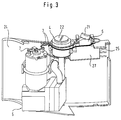
- FIGS. 3 and 4 show the internal structure of the compressor housing 2.
- An electrical connection to the energy supply part 3 is created at an energy absorption part 25 closed off with a plate 27, so that the electrical connection elements 7 connect the compressor 5 to the energy supply part 3 via the switch 6 when the energy supply part 3 is inserted.
- the switch 6 is a simple on / off switch, but a multi-stage switch can also be provided for multi-stage compressor operation.
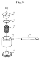
- the compressor 5 is shown. This comprises an electric motor 51 which is supplied with energy via connections 52, these connections 52 preferably via a capacitor 53 are connected. Furthermore, the compressor 5 comprises an actual compressor part 54, which contains the compression mechanism, as well as an inlet air hose 55 or an inlet air pipe 55 and an outlet hose 56 or an outlet pipe 56. The inlet air element 55 is connected to the inlet air filter 4, while the outlet element 56 for removal the compressed air is connected to the outlet port 26.
- the outlet connector 26 can have an interface (not shown) at its end facing away from the output element 56 (not shown), via which an atomizer can be connected to the compressor, but the interface can also be provided at the connection to the nebulizer (not shown) be so that the end facing away from the output element 56 is a simple opening.
- the device is preferably dimensioned so that depth (T in Fig. 1) and height (H in Fig. 1) of the compressor housing 2 and the energy supply part 3 correspond to the depth and height of the nebulizer container (not shown), so that a compact and easy-to-use inhaler is created.
- this is achieved in that the compressor 5 and the supply air filter 4 are arranged one above the other in the central region of the housing, so that space is left on one side for the nebulizer holder 24 and on the other for the energy supply part 3 .
Landscapes
- Health & Medical Sciences (AREA)
- Engineering & Computer Science (AREA)
- Bioinformatics & Cheminformatics (AREA)
- Pulmonology (AREA)
- Anesthesiology (AREA)
- Biomedical Technology (AREA)
- Heart & Thoracic Surgery (AREA)
- Hematology (AREA)
- Life Sciences & Earth Sciences (AREA)
- Animal Behavior & Ethology (AREA)
- General Health & Medical Sciences (AREA)
- Public Health (AREA)
- Veterinary Medicine (AREA)
- Compressor (AREA)
- Filtering Of Dispersed Particles In Gases (AREA)
- Medicinal Preparation (AREA)
- Nozzles (AREA)
Abstract
Description
- Gegenstand der Erfindung ist ein tragbares Inhalator-Kompressorgerät, d.h. ein kompaktes und tragbares Gerät, welches einen Kompressor, einen Luftfilter und eine Energieversorgung enthält, und welches zusammen mit einem Aerosolvernebler die ortsungebundene Durchführung einer Medikamentenverabreichung durch Inhalation ermöglicht.
- Die Verabreichung von Medikamenten in Form eines einzuatmenden Aerosols ist eine weitverbreitete Therapieform. Hierbei gilt es einen Wirkstoff so aufzubereiten, daß eine Suspension von Tröpfchen oder Teilchen in Luft entsteht, wobei der mittlere Durchmesser dieser Tröpfchen oder Teilchen gezielt einstellbar sein sollte, da die Größe angibt wo im Körper der Wirkstoff beim Inhalieren vornehmlich deponiert wird; größere Teilchen werden hauptsächlich im Mund- und Rachenraum abgeschieden, kleinere dringen bis in die Bronchien und Lungen vor. Die Tröpfchen können direkt aus der zu verabreichenden flüssigen Wirkstofflösung bestehen, oder aber auch aus in Flüssigkeit suspendierten festen Wirkstoffpartikeln. Schließlich ist es auch möglich einen pulverförmigen Feststoff direkt mit Luft zu vermischen.
- Ein bekanntes Prinzip der Aerosolerzeugung ist die Zuführung von von einem Kompressor verdichteter Luft zu einer Dispergiervorrichtung, beispielsweise einer Düse, in der die unter einem vorbestimmten Druck stehende Luft mit der den Wirkstoff enthaltenden Flüssigkeit vermischt wird.
- Die bekannten Kompressor-Inhaltionsgeräte haben jedoch den Nachteil, daß der Kompressor voluminös ist und die Abmessungen des Gesamtgerätes bestimmt. Solche bekannten Geräte sind kleinstenfalls Tisch- bzw. Koffergeräte, die zwar transportabel sind, jedoch zu groß sind um sie ständig bei sich zu führen oder an beliebigen Orten einzusetzen.
- Im Rahmen vieler Therapien ist es aber notwendig, daß ein Patient in kurzen Intervallen, d.h. mehrmals am Tag inhaliert. Dies kann seine Ursache darin haben, daß eine ständige Medikamentzufuhr nötig ist zur Beherrschung von Symptomen oder auch weil eine bestimmte Tagesgesamtdosis nicht auf einmal verabreicht werden kann. In diesem Fall ist es wünschenswert, daß der Patient ein Inhalationsgerät mit sich führen kann, so daß seine Mobilität nicht eingeschränkt wird und er damit seinem gewohnten Lebensrhythmus folgen kann.
- Zu diesem Zweck gibt es seit langem Tascheninhalatoren mit Handpumpen oder mit Druckpatronen. Diese erlauben jedoch nur eine sehr grobe Dosierung und haben nur einen geringen Wirkungsgrad was das Verhältnis von eingesetzter zu verwertbarer Medikamentmenge angeht, so daß solche Inhalatoren für eine dosisgenaue Therapie ungeeignet sind. Ebenfalls bekannt ist eine kompakte, elektrisch betriebene Vorrichtung, die einen Ultraschallvernebler aufweist. Solche Ultraschallvernebler haben jedoch Nachteile gegenüber kompressorbetriebenen Inhalationsgeräten was die Einsatzbreite mit verschiedenen Medikamentenformulierungen sowie die Steuerbarkeit der Aerosolapplikation angeht.
- Es ist die Aufgabe der vorliegenden Erfindung, das Kompressorgerät für ein tragbares, kompressorbetriebenes Inhalationsgerät zu schaffen welches von einem Patienten problemlos und bequem ständig bei sich geführt werden kann und dabei jederzeit einsetzbar ist. Das Gehäuse des Kompressorgeräts sollte dabei in Form und Größe an das Verneblergefäß angepaßt sein.
- Die Lösung dieser Aufgabe geschieht mit einer Vorrichtung gemäß des Wortlauts des ersten Schutzanspruches.
- Die Erfindung wird nun anhand von Ausführungsbeispielen und unter Bezugnahme auf die begleitenden Figuren erläutert, wobei die Zeichnungen folgendes zeigen:
- Fig. 1
- zeigt eine Perspektivansicht des erfindungsgemäßen Inhalator-Kompressorgeräts;
- Fig. 2
- zeigt das Kompressorgehäuse und den herausnehmbaren Energieversorgungsteil;
- Fig. 3
- zeigt die Anordnung des Kompressors, des Luftfilters und des elektrischen Einschalters auf dem Rückenelement des Gehäuses;
- Fig. 4
- zeigt den Zusammenbau der Teile, die zur Anordnung von Fig. 3 führen;
- Fig. 5
- zeigt den Aufbau des Kompressors;
- Fig. 6
- zeigt den Aufbau des Zuluftfilters.
- In Figur 1 ist eine Perspektivansicht des Kompressorgerätes 1 dargestellt. Es besteht aus dem Kompressorgehäuse 2 und dem Energieversorgungsteil 3. Das Kompressorgehäuse umfaßt eine Schaltertaste 21 und eine Luftfilteraufnahme 22. An dem dem Energieversorgungsteil 3 gegenüberliegenden Ende des Geräts ist eine Halterung 23 zur Aufnahme eines Verneblergefäßes (nicht abgebildet) vorgesehen. Dies ermöglicht den Betrieb des Kompressors zusammen mit verschiedenen Verneblergefäßen und gibt der Erfindung damit eine hohe Flexibilität in Bezug auf den individuellen Einsatz bei bestimmten Patienten bzw. bei speziellen Therapien.
- Figur 2 zeigt, daß das Energieversorgungsteil 3 vorzugsweise aus einer Aussparung 28 im Kompressorgehäuse 2 herausnehmbar ist. Dieses Energieversorgungsteil 3 ist gewöhnlich ein einfacher Akkumulator, der an einem externen Ladegerät aufgeladen werden kann und über Anzeigeelemente 31 Auskunft über sehnen Betriebs- und Ladezustand gibt. Das Energieversorgungsteil 3 kann jedoch auch ein Netzadapter sein um das Kompressorgerät 1 an eine Netzversorgung anzuschließen wenn eine solche zur Verfügung steht. Hierunter ist nicht nur das öffentliche Stromversorgungsnetz ("Steckdose") zu verstehen, sondern alle möglichen externen Energiequellen, wie z.B. Zigarettenanzünder in Kraftfahrzeugen. Schließlich ist auch ein kombiniertes Energieversorgungsteil 3 denkbar, in welchem Akkumulator und Adapter in einem einzigen Einsteckelement vereinigt sind. Hierbei könnte der Energieversorgungsteil dann so aufgebaut sein, daß bei Betrieb des Gerätes mit einer Energieversorgung aus einem externen Netz gleichzeitig der Akkumulator aufgeladen wird.
- Durch diese flexible Energieversorgung ist gewährleistet, daß das Kompressorgerät 1 stets einsatzbereit ist und gleichzeitig aber auch immer mit der gerade zur Verfügung stehenden, den Akkumulator schonenden externen Energiequelle betrieben werden kann.
- In den Figuren 3 und 4 ist der innere Aufbau des Kompressorgehäuses 2 dargestellt. Man erkennt einen Ansaugluftfilter 4, einen Kompressor 5, einen elektrischen Schalter 6, sowie elektrische Verbindungselemente 7, die alle zusammen auf dem Rückensegment 24 des Kompressorgehäuses 2 angeordnet sind. An einem mit einer Platte 27 abgeschlossenen Energieaufnahmeteil 25 wird eine elektrische Verbindung zum Energieversorgungsteil 3 geschaffen, so daß die elektrischen Verbindungselemente 7 den Kompressor 5 über den Schalter 6 mit dem Energieversorgungsteil 3 verbinden wenn das Energieversorgungsteil 3 eingesetzt ist. Im einfachsten Fall ist der Schalter 6 ein einfacher Ein/Aus-Schalter, es kann aber auch ein mehrstufiger Schalter vorgesehen werden zum mehrstufigen Kompressorbetrieb.
- In Figur 5 ist der Kompressor 5 dargestellt. Dieser umfaßt einen Elektromotor 51, der über Anschlüsse 52 mit Energie versorgt wird, wobei diese Anschlüsse 52 vorzugsweise über einen Kondensator 53 verbunden sind. Ferner umfaßt der Kompressor 5 einen eigentlichen Kompressorteil 54, welcher die Kompressionsmechanik enthält, sowie einen Zuluftschlauch 55 bzw. ein Zuluftrohr 55 und einen Ausgangsschlauch 56 bzw. ein Ausgangsrohr 56. Das Zuluftelement 55 ist mit dem Zuluftfilter 4 verbunden, während das Ausgangselement 56 zur Abführung der verdichteten Luft mit dem Ausgangsstutzen 26 verbunden ist. Der Ausgangsstutzen 26 kann an seinem dem Ausgangselement 56 abgewandten Ende (nicht abgebildet) über eine Schnittstelle (nicht abgebildet) verfügen, über die ein Vernebler an den Kompressor angeschlossen werden kann, die Schnittstelle kann jedoch auch an der Verbindung zum Vernebler (nicht abgebildet) vorgesehen sein, so daß das dem Ausgangselement 56 abgewandte Ende eine einfache Öffnung ist.
- Figur 6 zeigt den Aufbau des Zuluftfilters 4. Es umfaßt die Filteraufnahme 22, einen O-Ring 41, das eigentliche Filterelement 42, das Filtergehäuse 43, einen Ansaugschlauch 44 sowie den Filterboden 45. Diese werden wie in Fig. 6 angedeutet zusammengesetzt, und wie in den Figuren 3 und 4 gezeigt mit dem Kompressor 5 und dem Rückensegment 24 verbunden. Die Filteraufnahme 22 umfaßt einen Drehverschluß zum Fixieren des Filterelements 42 im Filtergehäuse 43. In die Kerbe 220 im Deckel der Filteraufnahme 22 paßt z.B. eine Münze, so daß jeder Benutzer des Geräts das Filterelement 42 durch Aufdrehen der Filteraufnahme 22 bei Bedarf wechseln kann.
- Im einfachsten Fall ist das Filterelement 42 ein einfacher Staubfilter um zu verhindern, daß der Kompressor verstopft, es ist aber auch denkbar, speziellere Filter einzusetzen, die zusätzlich bestimmte Stoffe bevorzugt filtern, wie z.B. Feuchtigkeit. Ebenfalls möglich ist das Vorsehen eines Sensors (nicht abgebildet) zur Bestimmung des Beladungszustandes, wobei ein notwendiger Wechsel des Filterelements 42 dann über ein geeignetes Anzeigeinstrument, z.B. eine Kontrolleuchte, angezeigt werden kann.
- Das Gerät ist vorzugsweise so zu dimensionieren, daß Tiefe (T in Fig. 1) und Höhe (H in Fig. 1) des Kompressorgehäuses 2 und des Energieversorgungsteils 3 der Tiefe und Höhe des Verneblergefäßes (nicht abgebildet) entsprechen, so daß ein kompaktes und leicht zu handhabendes Inhaliergerät entsteht. Dies ist bei dem in den Zeichnungen gezeigten Ausführungsbeispiel dadurch erreicht, daß der Kompressor 5 und der Zuluftfilter 4 übereinander im mittleren Bereich des Gehäuses angeordnet sind, so daß auf der einen Seite Raum gelassen wird für die Verneblerhalterung 24 und auf der anderen für das Energieversorgungsteil 3.
- In einer weiteren bevorzugten Ausführungsform ist die Form des Kompressorgehäuses in seiner Längsausdehnung (L in Fig. 1) leicht gekrümmt, wie in Figur 1 angedeutet. Dies erleichert das Tragen des Geräts am Körper, z.B. an der Hüfte mit Hilfe einer Gürteltasche oder eines Gürtelhalters. Ebenso ist das Gehäuse vorzugsweise mit einer gerippten Oberfläche zu versehen, um eine sichere Handhabung des Geräts zu gewährleisten, das heißt, daß es nicht leicht aus der Hand gleitet.
Claims (6)
- Tragbares Inhalator-Kompressorgerät (1) umfassend:- ein Kompressorgehäuse (2), in welchem ein elektrisch angetriebener Kompressor (5) und ein Zuluftfilter (4) zur Filterung der dem Kompressor (5) zugeführten Luft angeordnet sind und welches mit einer Halterung (23) zur Aufnahme eines Verneblergefäßes, dessen Breite im wesentlichen die Breite des Kompressorgehäuses bestimmt, ausgestattet ist, und- ein Energieversorgungsteil (3), welches zur Versorgung des Kompressors mit elektrischer Energie in eine Aussparung (28) im Kompressorgehäuse einführbar ist.
- Tragbares Inhalator-Kompressorgerät nach Anspruch 1, dadurch gekennzeichnet, daß der Energieversorgungsteil (3) einen Akkumulator umfaßt.
- Tragbares Inhalator-Kompressorgerät nach Anspruch 1 oder 2, dadurch gekennzeichnet, daß der Energieversorgungsteil (3) einen Netzadapter zur Versorgung des Gerätes mit Energie aus einem externen Netz umfaßt.
- Tragbares Inhalator-Kompressorgerät nach einem der Ansprüche 1 bis 3, dadurch gekennzeichnet, daß die Form des Kompressorgehäuses (2) und des Energieversorgungsteils (3) so gewählt sind, daß die Form des Inhalator-Kompressorgeräts (1) in seiner Längsausdehnung (L) gekrümmt ist.
- Tragbares Inhalator-Kompressorgerät nach einem der Ansprüche 1 bis 4,
dadurch gekennzeichnet, daß
die Halterung (23) an einem schmalseitigen Ende des Kompressorgehäuses (2) und die Aussparung (28) an dem gegenüberliegenden, schmalseitigen Ende des Kompressorgehäuses (2) angeordnet ist. - Tragbares Inhalator-Kompressorgerät nach Anspruch 5,
dadurch gekennzeichnet, daß
die Länge des Verneblergehäuses im wesentlichen die Höhe des Kompressorgehäuses (2) bestimmt.
Applications Claiming Priority (2)
| Application Number | Priority Date | Filing Date | Title |
|---|---|---|---|
| DE9418334U DE9418334U1 (de) | 1994-11-15 | 1994-11-15 | Tragbares Inhalator-Kompressorgerät |
| DE9418334U | 1994-11-15 |
Publications (2)
| Publication Number | Publication Date |
|---|---|
| EP0712636A1 true EP0712636A1 (de) | 1996-05-22 |
| EP0712636B1 EP0712636B1 (de) | 2001-07-11 |
Family
ID=6916189
Family Applications (1)
| Application Number | Title | Priority Date | Filing Date |
|---|---|---|---|
| EP95116799A Expired - Lifetime EP0712636B1 (de) | 1994-11-15 | 1995-10-25 | Tragbares Inhalator-Kompressorgerät |
Country Status (4)
| Country | Link |
|---|---|
| EP (1) | EP0712636B1 (de) |
| JP (1) | JPH08206206A (de) |
| AT (1) | ATE202943T1 (de) |
| DE (2) | DE9418334U1 (de) |
Cited By (7)
| Publication number | Priority date | Publication date | Assignee | Title |
|---|---|---|---|---|
| WO1998051361A3 (en) * | 1997-05-12 | 1999-03-18 | Emily L Cooper | Device for nasal therapeutic inhalation |
| EP1106195A1 (de) * | 1999-12-03 | 2001-06-13 | Medel, S.p.A. | Vorrichtung zum Vernebeln einer Flüssigkeit, insbesondere für medizinische Anwendungen |
| EP1721627A1 (de) * | 2005-05-13 | 2006-11-15 | PARI GmbH Spezialisten für effektive Inhalation | Inhalationstherapievorrichtung mit Verneblerdüse und Kompressor |
| WO2007036966A1 (en) * | 2005-09-30 | 2007-04-05 | Medel S.P.A. | Apparatus for aerosol therapy |
| EP1776976A1 (de) | 2005-10-20 | 2007-04-25 | PARI GmbH Spezialisten für effektive Inhalation | Inhalationsgerätekompressor für eine Inhalationstherapievorrichtung |
| CN105597202A (zh) * | 2016-02-04 | 2016-05-25 | 深圳金亿帝医疗设备股份有限公司 | 雾化器及雾化器主体 |
| ITUA20163840A1 (it) * | 2016-05-26 | 2017-11-26 | 3A Health Care S R L | Unità compressore per un apparecchio per il trattamento delle vie respiratorie |
Citations (4)
| Publication number | Priority date | Publication date | Assignee | Title |
|---|---|---|---|---|
| DE2449816A1 (de) * | 1973-10-24 | 1975-05-07 | Paul Guichard | Tragbares nasal-diffusor-geraet zum reinigen und modifizieren der atmungsluft |
| DE3043325A1 (de) * | 1980-11-17 | 1982-07-01 | Brugger, Inge, 8130 Starnberg | Inhalationsgeraet |
| US5022587A (en) * | 1989-06-07 | 1991-06-11 | Hochstein Peter A | Battery powered nebulizer |
| DE4306458A1 (de) * | 1993-03-02 | 1994-09-15 | Lindopharm Gmbh | Vernebler für therapeutsche Zwecke |
-
1994
- 1994-11-15 DE DE9418334U patent/DE9418334U1/de not_active Expired - Lifetime
-
1995
- 1995-10-25 DE DE59509403T patent/DE59509403D1/de not_active Expired - Fee Related
- 1995-10-25 EP EP95116799A patent/EP0712636B1/de not_active Expired - Lifetime
- 1995-10-25 AT AT95116799T patent/ATE202943T1/de not_active IP Right Cessation
- 1995-11-15 JP JP7330959A patent/JPH08206206A/ja not_active Withdrawn
Patent Citations (4)
| Publication number | Priority date | Publication date | Assignee | Title |
|---|---|---|---|---|
| DE2449816A1 (de) * | 1973-10-24 | 1975-05-07 | Paul Guichard | Tragbares nasal-diffusor-geraet zum reinigen und modifizieren der atmungsluft |
| DE3043325A1 (de) * | 1980-11-17 | 1982-07-01 | Brugger, Inge, 8130 Starnberg | Inhalationsgeraet |
| US5022587A (en) * | 1989-06-07 | 1991-06-11 | Hochstein Peter A | Battery powered nebulizer |
| DE4306458A1 (de) * | 1993-03-02 | 1994-09-15 | Lindopharm Gmbh | Vernebler für therapeutsche Zwecke |
Cited By (10)
| Publication number | Priority date | Publication date | Assignee | Title |
|---|---|---|---|---|
| WO1998051361A3 (en) * | 1997-05-12 | 1999-03-18 | Emily L Cooper | Device for nasal therapeutic inhalation |
| GB2340406A (en) * | 1997-05-12 | 2000-02-23 | Emily Cooper | Device for nasal therapeutic inhalation |
| US6076520A (en) * | 1997-05-12 | 2000-06-20 | Cooper; Emily L. | Device for nasal therapeutic inhalation |
| EP1106195A1 (de) * | 1999-12-03 | 2001-06-13 | Medel, S.p.A. | Vorrichtung zum Vernebeln einer Flüssigkeit, insbesondere für medizinische Anwendungen |
| US6698421B2 (en) | 1999-12-03 | 2004-03-02 | Medel S.P.A. | Apparatus for nebulizing a liquid, in particular for medical use |
| EP1721627A1 (de) * | 2005-05-13 | 2006-11-15 | PARI GmbH Spezialisten für effektive Inhalation | Inhalationstherapievorrichtung mit Verneblerdüse und Kompressor |
| WO2007036966A1 (en) * | 2005-09-30 | 2007-04-05 | Medel S.P.A. | Apparatus for aerosol therapy |
| EP1776976A1 (de) | 2005-10-20 | 2007-04-25 | PARI GmbH Spezialisten für effektive Inhalation | Inhalationsgerätekompressor für eine Inhalationstherapievorrichtung |
| CN105597202A (zh) * | 2016-02-04 | 2016-05-25 | 深圳金亿帝医疗设备股份有限公司 | 雾化器及雾化器主体 |
| ITUA20163840A1 (it) * | 2016-05-26 | 2017-11-26 | 3A Health Care S R L | Unità compressore per un apparecchio per il trattamento delle vie respiratorie |
Also Published As
| Publication number | Publication date |
|---|---|
| EP0712636B1 (de) | 2001-07-11 |
| DE9418334U1 (de) | 1995-01-26 |
| DE59509403D1 (de) | 2001-08-16 |
| ATE202943T1 (de) | 2001-07-15 |
| JPH08206206A (ja) | 1996-08-13 |
Similar Documents
| Publication | Publication Date | Title |
|---|---|---|
| EP0302958B1 (de) | Transportables Inhalationsgerät | |
| DE2849493A1 (de) | In der hand zu haltender aerosolspender | |
| EP0258637B1 (de) | Ultraschall-Taschenzerstäubergerät | |
| EP0610350B1 (de) | Handvernebler für das zerstäuben von therapeutischen flüssigkeiten | |
| DE69633645T2 (de) | Vorrichtung zum Verabreichen von Medikamenten | |
| DE69129188T2 (de) | Inhalator mit einem reservoir für mehrere dosierte inhalationsmittel, mit transportvorrichtung und mit wirbelkammer | |
| DE3787977T2 (de) | Anordnung zur selbstverabreichung physiologisch aktiver substanzen unter vorbeugung einer überdosierung. | |
| DE69822885T2 (de) | Inhalationsvorrichtung | |
| DE69616324T2 (de) | Vorrichtung für inhalator | |
| DE69608561T2 (de) | Inhaliervorrichtung und methode | |
| DE69002581T2 (de) | Multi-Dosierungsinhalierer für Medikamente in Pulverform. | |
| EP0147755B1 (de) | Inhalator | |
| EP1239905B9 (de) | Vorratssystem für arzneimittel in pulverform und damit ausgestatteter inhalator | |
| EP0545960B1 (de) | Treibgasfreies inhalationsgerät | |
| DE69511102T2 (de) | Wiederbelebungsgerät | |
| DE69909764T2 (de) | Inhalationsvorrichtung | |
| DE69918965T2 (de) | Inhalator mit dosierzähleinheit | |
| DE2537765A1 (de) | Medizinisches inhalationsgeraet zur behandlung von krankheiten der atmungswege | |
| EP0171726A2 (de) | Inhalator | |
| PT904056E (pt) | Processo e dispositivo para inalacao de medicamentos particulados | |
| EP0712636B1 (de) | Tragbares Inhalator-Kompressorgerät | |
| US20020005196A1 (en) | Portable inhalator compressor device | |
| EP0572969A1 (de) | Inhalator | |
| DE2013504A1 (de) | Anschlußschnurloser elektrischer Zerstäuber | |
| DE4306458A1 (de) | Vernebler für therapeutsche Zwecke |
Legal Events
| Date | Code | Title | Description |
|---|---|---|---|
| PUAI | Public reference made under article 153(3) epc to a published international application that has entered the european phase |
Free format text: ORIGINAL CODE: 0009012 |
|
| AK | Designated contracting states |
Kind code of ref document: A1 Designated state(s): AT BE CH DE DK ES FR GB GR IE IT LI NL PT SE |
|
| 17P | Request for examination filed |
Effective date: 19960621 |
|
| RAP1 | Party data changed (applicant data changed or rights of an application transferred) |
Owner name: PARI GMBH SPEZIALISTEN FUER EFFEKTIVE INHALATION |
|
| 17Q | First examination report despatched |
Effective date: 19990209 |
|
| GRAG | Despatch of communication of intention to grant |
Free format text: ORIGINAL CODE: EPIDOS AGRA |
|
| GRAG | Despatch of communication of intention to grant |
Free format text: ORIGINAL CODE: EPIDOS AGRA |
|
| GRAH | Despatch of communication of intention to grant a patent |
Free format text: ORIGINAL CODE: EPIDOS IGRA |
|
| GRAH | Despatch of communication of intention to grant a patent |
Free format text: ORIGINAL CODE: EPIDOS IGRA |
|
| GRAA | (expected) grant |
Free format text: ORIGINAL CODE: 0009210 |
|
| AK | Designated contracting states |
Kind code of ref document: B1 Designated state(s): AT BE CH DE DK ES FR GB GR IE IT LI NL PT SE |
|
| PG25 | Lapsed in a contracting state [announced via postgrant information from national office to epo] |
Ref country code: IE Free format text: LAPSE BECAUSE OF FAILURE TO SUBMIT A TRANSLATION OF THE DESCRIPTION OR TO PAY THE FEE WITHIN THE PRESCRIBED TIME-LIMIT Effective date: 20010711 Ref country code: GR Free format text: LAPSE BECAUSE OF NON-PAYMENT OF DUE FEES Effective date: 20010711 Ref country code: FR Free format text: LAPSE BECAUSE OF FAILURE TO SUBMIT A TRANSLATION OF THE DESCRIPTION OR TO PAY THE FEE WITHIN THE PRESCRIBED TIME-LIMIT Effective date: 20010711 |
|
| REF | Corresponds to: |
Ref document number: 202943 Country of ref document: AT Date of ref document: 20010715 Kind code of ref document: T |
|
| REG | Reference to a national code |
Ref country code: CH Ref legal event code: EP |
|
| REF | Corresponds to: |
Ref document number: 59509403 Country of ref document: DE Date of ref document: 20010816 |
|
| REG | Reference to a national code |
Ref country code: IE Ref legal event code: FG4D Free format text: GERMAN |
|
| ITF | It: translation for a ep patent filed | ||
| PG25 | Lapsed in a contracting state [announced via postgrant information from national office to epo] |
Ref country code: SE Free format text: LAPSE BECAUSE OF FAILURE TO SUBMIT A TRANSLATION OF THE DESCRIPTION OR TO PAY THE FEE WITHIN THE PRESCRIBED TIME-LIMIT Effective date: 20011011 Ref country code: PT Free format text: LAPSE BECAUSE OF FAILURE TO SUBMIT A TRANSLATION OF THE DESCRIPTION OR TO PAY THE FEE WITHIN THE PRESCRIBED TIME-LIMIT Effective date: 20011011 Ref country code: DK Free format text: LAPSE BECAUSE OF FAILURE TO SUBMIT A TRANSLATION OF THE DESCRIPTION OR TO PAY THE FEE WITHIN THE PRESCRIBED TIME-LIMIT Effective date: 20011011 |
|
| GBT | Gb: translation of ep patent filed (gb section 77(6)(a)/1977) |
Effective date: 20010926 |
|
| PG25 | Lapsed in a contracting state [announced via postgrant information from national office to epo] |
Ref country code: AT Free format text: LAPSE BECAUSE OF NON-PAYMENT OF DUE FEES Effective date: 20011025 |
|
| PGFP | Annual fee paid to national office [announced via postgrant information from national office to epo] |
Ref country code: NL Payment date: 20011031 Year of fee payment: 7 |
|
| REG | Reference to a national code |
Ref country code: CH Ref legal event code: NV Representative=s name: E. BLUM & CO. PATENTANWAELTE |
|
| PGFP | Annual fee paid to national office [announced via postgrant information from national office to epo] |
Ref country code: CH Payment date: 20011105 Year of fee payment: 7 |
|
| PGFP | Annual fee paid to national office [announced via postgrant information from national office to epo] |
Ref country code: BE Payment date: 20011119 Year of fee payment: 7 |
|
| EN | Fr: translation not filed | ||
| REG | Reference to a national code |
Ref country code: GB Ref legal event code: IF02 |
|
| PG25 | Lapsed in a contracting state [announced via postgrant information from national office to epo] |
Ref country code: ES Free format text: LAPSE BECAUSE OF FAILURE TO SUBMIT A TRANSLATION OF THE DESCRIPTION OR TO PAY THE FEE WITHIN THE PRESCRIBED TIME-LIMIT Effective date: 20020131 |
|
| PLBE | No opposition filed within time limit |
Free format text: ORIGINAL CODE: 0009261 |
|
| STAA | Information on the status of an ep patent application or granted ep patent |
Free format text: STATUS: NO OPPOSITION FILED WITHIN TIME LIMIT |
|
| 26N | No opposition filed | ||
| PGFP | Annual fee paid to national office [announced via postgrant information from national office to epo] |
Ref country code: GB Payment date: 20020913 Year of fee payment: 8 |
|
| PG25 | Lapsed in a contracting state [announced via postgrant information from national office to epo] |
Ref country code: LI Free format text: LAPSE BECAUSE OF NON-PAYMENT OF DUE FEES Effective date: 20021031 Ref country code: CH Free format text: LAPSE BECAUSE OF NON-PAYMENT OF DUE FEES Effective date: 20021031 Ref country code: BE Free format text: LAPSE BECAUSE OF NON-PAYMENT OF DUE FEES Effective date: 20021031 |
|
| BERE | Be: lapsed |
Owner name: *PARI G.M.B.H. SPEZIALISTEN FUR EFFEKTIVE INHALATI Effective date: 20021031 |
|
| PG25 | Lapsed in a contracting state [announced via postgrant information from national office to epo] |
Ref country code: NL Free format text: LAPSE BECAUSE OF NON-PAYMENT OF DUE FEES Effective date: 20030501 |
|
| REG | Reference to a national code |
Ref country code: CH Ref legal event code: PL |
|
| NLV4 | Nl: lapsed or anulled due to non-payment of the annual fee |
Effective date: 20030501 |
|
| PG25 | Lapsed in a contracting state [announced via postgrant information from national office to epo] |
Ref country code: GB Free format text: LAPSE BECAUSE OF NON-PAYMENT OF DUE FEES Effective date: 20031025 |
|
| PGFP | Annual fee paid to national office [announced via postgrant information from national office to epo] |
Ref country code: DE Payment date: 20031030 Year of fee payment: 9 |
|
| GBPC | Gb: european patent ceased through non-payment of renewal fee |
Effective date: 20031025 |
|
| PG25 | Lapsed in a contracting state [announced via postgrant information from national office to epo] |
Ref country code: DE Free format text: LAPSE BECAUSE OF NON-PAYMENT OF DUE FEES Effective date: 20050503 |
|
| PG25 | Lapsed in a contracting state [announced via postgrant information from national office to epo] |
Ref country code: IT Free format text: LAPSE BECAUSE OF NON-PAYMENT OF DUE FEES;WARNING: LAPSES OF ITALIAN PATENTS WITH EFFECTIVE DATE BEFORE 2007 MAY HAVE OCCURRED AT ANY TIME BEFORE 2007. THE CORRECT EFFECTIVE DATE MAY BE DIFFERENT FROM THE ONE RECORDED. Effective date: 20051025 |