EP1776171B1 - Improved compressor device - Google Patents
Improved compressor device Download PDFInfo
- Publication number
- EP1776171B1 EP1776171B1 EP05763965.0A EP05763965A EP1776171B1 EP 1776171 B1 EP1776171 B1 EP 1776171B1 EP 05763965 A EP05763965 A EP 05763965A EP 1776171 B1 EP1776171 B1 EP 1776171B1
- Authority
- EP
- European Patent Office
- Prior art keywords
- compressor
- blow
- air
- connecting pipe
- compressed
- Prior art date
- Legal status (The legal status is an assumption and is not a legal conclusion. Google has not performed a legal analysis and makes no representation as to the accuracy of the status listed.)
- Expired - Lifetime
Links
Images


Classifications
-
- B—PERFORMING OPERATIONS; TRANSPORTING
- B01—PHYSICAL OR CHEMICAL PROCESSES OR APPARATUS IN GENERAL
- B01D—SEPARATION
- B01D53/00—Separation of gases or vapours; Recovering vapours of volatile solvents from gases; Chemical or biological purification of waste gases, e.g. engine exhaust gases, smoke, fumes, flue gases, aerosols
- B01D53/26—Drying gases or vapours
- B01D53/261—Drying gases or vapours by adsorption
-
- Y—GENERAL TAGGING OF NEW TECHNOLOGICAL DEVELOPMENTS; GENERAL TAGGING OF CROSS-SECTIONAL TECHNOLOGIES SPANNING OVER SEVERAL SECTIONS OF THE IPC; TECHNICAL SUBJECTS COVERED BY FORMER USPC CROSS-REFERENCE ART COLLECTIONS [XRACs] AND DIGESTS
- Y10—TECHNICAL SUBJECTS COVERED BY FORMER USPC
- Y10S—TECHNICAL SUBJECTS COVERED BY FORMER USPC CROSS-REFERENCE ART COLLECTIONS [XRACs] AND DIGESTS
- Y10S55/00—Gas separation
- Y10S55/17—Compressed air water removal
Definitions
- the present invention concerns an improved compressor device.
- the invention in particular concerns a compressor device of the type which consists of a compressor with an inlet and an outlet; a compressed air line suitable for connecting the outlet of the compressor to a user network; a drier which is incorporated in the above-mentioned compressed air line and which comprises at least two air receivers which are each provided with an intake and an output and which are filled with desiccant or drying agent, which air receivers work alternately, such that while one air receiver is drying the compressed gas, the other air receiver is regenerated by heat of the gas compressed by the compressor; and a blow-off device to blow off at least a part of the gas compressed by the compressor when the compressor operates in no-load or partial load, whereby means are provided which make it possible to guide the entire non-cooled compressed gas flow coming from the outlet of the compressor, through the regenerating air receiver before at least part of this compressed gas is blown off via the blow-off device into the atmosphere.
- this entire maximum output of compressed gas is sent at the outlet of the compressor through the regenerating air receiver so as to extract moisture from the drying agent in said air receiver by making use of the heat of this compressed gas, and to thus regenerat 3 e drying agent.
- a disadvantage of such known type of compressor device is that, in partial load operation, only a part of the available output of the compressor is used to regenerate the drying agent in the regenerating air receiver, which may lead to insufficient regeneration of the drying agent under certain circumstances.
- U.S. 2003/0233941 describes a desiccant dryer regeneration system able to operate in a heating cycle, a stripping cycle and a cooling cycle.
- U.S. 6.375.722 reflates to a heat of compression dryer connected to a compressor.
- US 4.783.432 describes as method and apparatus for regenerating desiccant in an adsorption dryer using two-phase regeneration.
- US 3.205.638 relates to a method and apparatus for dehydration of gases.
- the invention aims to remedy the above-mentioned and other disadvantages by providing a compressor device whereby the entire compressor output is always used for regenerating the drying agent, irrespective of the comsumption, and thus irrespective of whether the compressor device operates in full load, in partial load or in no-load.
- the invention concerns an improved compressor device of the above-mentioned type, whereby a controller is provided, which controller is adapted to perform the method of claim 1.
- the above-mentioned means comprise one or several connecting pipes between the intakes of the above-mentioned air receivers, and the blow-off device is formed by a branch which is connected to one of these connecting pipes.
- a throttle valve is provided in the inlet of the compressor which is activated when the compressor operates in no-load, such that in no-load, the compressed air is additionally heated as a result of the throttling, and a more efficient regeneration is thus obtained.
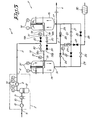
- the compressor device 1 of figure 1 mainly consists of a compressor 2 with an inlet 3 and an outlet 4; a compressed air line 5 which connects the outlet 4 of the compressor 2 to a user network 6 and a drier 7 which is incorporated in the above-mentioned compressed air line 5.
- the compressor 2 in this case mainly consists of a low pressure stage 8 and a high pressure stage 9 connected in series by means of a pressure pipe 10 in which are successively incorporated an intercooler 11 and a water separator 12.
- the drier 7 contains a first insulated air receiver 13, with an inlet 14 and an outlet 15 containing silica gel or any other drying agent whatsoever; a second insulated air receiver 16, with an inlet 17 and an outlet 18 which also comprises silica gel as a drying agent.
- Each of the outlets 15 and 18 of both air receivers 13 and 16 is connected, via a split pipe 19 and a valve 20 in each split part 19A and 19B of the pipe 19, to the compressed air line 5, whereby this compressed air line 5 is interrupted between the above-mentioned connections of the split parts 19A and 19B on the compressed air line 5.
- the inlets 14 are mutually connected by means of three connecting pipes, a first connecting pipe 21 with two stop cocks 22, a second connecting pipe 23 with non-return valves working in the opposite direction and a third connecting pipe 25 respectively, with two stop cocks 26 as well.
- the first and second connecting pipes are bridged by a cooler 27 which is connected with its inlet to the second connecting pipe 23, more particularly between the non-return valves 24 in this pipe 23, and which is connected with its outlet to the first connecting pipe 21, more particularly between the stop cocks 22 of this pipe 21.
- a blow-off device 28 for blowing off compressed gas is provided in the form of a branch which is connected to the first connecting pipe 21 between the stop cocks 22 and which opens into the atmosphere.
- blow-off device 28 In this blow-off device 28 is provided a stop cock 29, as well as a sound absorber 30 at the output of the blow-off device 28.
- the blow-off device 28 is in this case also connected to the third connecting pipe 25, more particularly between the stop cocks 26 of this pipe and downstream in relation to the stop cock 29.
- the compressor device 1 is preferably also provided with a controller, not represented in the figures, which makes it possible to set the operating conditions of the compressor 2 and to open or close the valves 20 and stop cocks 22 and 26, depending on the required operating conditions of the compressor device 1.
- the compressor device 1 can also be provided with measuring equipment to measure temperatures, pressures and, if necessary, also the dew point, which measuring equipment is connected to the above-mentioned controller to control the compressor device 1.
- valves 20 and the stop cocks 22 and 26 are represented in black when closed and in white when open, and whereby the path followed by the compressed gas is represented in bold.
- Figure 1 represents the compressor device 1 when the compressor 2 operates in full load, i.e. at its maximum capacity.
- the entire non-cooled compressed gas flow, coming from the outlet 4 of the compressor 2 is guided counterflow through the air receiver 13, namely from the outlet 15 to the inlet 14, where this gas flow will regenerate the drying agent or desiccant, for example silica gel, making use of the heat contained in the compressed gas.
- the drying agent or desiccant for example silica gel
- the compressed gas flow goes to the cooler 27 where it is cooled, to be then guided through the air receiver 16 so as to dry the compressed gas.
- the outlet 18 of the air receiver 16 is at that time connected to the user network 6 onto which are connected one or several consumers of compressed gas, not represented here.
- Figure 2 represents the compressor device 1 in partial load operation whereby the user network 6 only requires a part of the output of the compressor 2.
- the entire output of the compressor 2 will flow through the regenerating air receiver, as opposed to the known systems whereby only the output required by the network 6 was sent through the regenerating vessel 13, and the excess output was blown off directly into the atmosphere at the outlet 4 of the compressor 2 without passing first through the regenerating air receiver 13.
- a compressor device 1 according to the invention offers the advantage that, also in partial load, the drying agent in the regenerating air receiver 13 is always maximally regenerated.
- Figure 3 shows an alternative of a partial load operation, whereby the excess output which is blown off into the atmosphere via the blow-off device 28 is in this case not branched downstream but upstream in relation to the cooler 27, such that no additional energy is required for cooling than said output blown off into the atmosphere.
- Figure 4 represents the no-load operation of the compressor device 1, whereby no compressed gas is taken by the user network 6 in this case.
- the compressor 2 is made to run idle and pressureless, whereby a minimum amount of gas is sucked in, compressed and blown off into the atmosphere.
- the compressed gas is not blown off directly at the outlet 4, but it is sent through the regenerating air receiver first to be then blown off into the atmosphere via the blow-off device 28.
- the output to be blown off is branched between the air receiver 13 and the non-return valve 24 in order to prevent gas under pressure from escaping from the user network 6 via the blow-off device 28 into the atmosphere.
- the inlet 3 of the compressor 2 may optionally be provided with a throttle device which is at least activated in no-load operation.
- the compressed gas reaches higher temperatures at the outlet 4 of the compressor, as a result of which a warmer gas is sent through the regenerating air receiver and a better regeneration of the drying agent is thus obtained.
- valves 20 and the connecting pipes 21, 23 and 25 with their respective stop cocks 22, 26 and non-return valves 24, other means can be provided which make it possible to send the excess, non-used part of the compressed gas through the regenerating air receiver 13 in partial load and in no-load operation.
- blow-off 28 must not necessarily take place in the atmosphere, but in the case of medical gases, for example, the blow-off can take place in a controlled environment at a pressure which is lower than the pressure at the outlet 4 of the compressor 2.
- the compressor 2 must not necessarily be a multi-stage compressor.
- the terminology of the intakes 14-17 and of the outlets 15-18 of the air receivers 13-16 are selected as a function of the operation of the air receivers as a drying air receiver.
- the compressed gas in the given example, flows counterflow through the air receiver 13 concerned, i.e. from the outlet to the inlet.
Landscapes
- Chemical & Material Sciences (AREA)
- Engineering & Computer Science (AREA)
- Analytical Chemistry (AREA)
- General Chemical & Material Sciences (AREA)
- Oil, Petroleum & Natural Gas (AREA)
- Chemical Kinetics & Catalysis (AREA)
- Drying Of Gases (AREA)
- Compressor (AREA)
Priority Applications (1)
| Application Number | Priority Date | Filing Date | Title |
|---|---|---|---|
| PL05763965T PL1776171T3 (pl) | 2004-08-02 | 2005-07-20 | Ulepszone urządzenie sprężarki |
Applications Claiming Priority (2)
| Application Number | Priority Date | Filing Date | Title |
|---|---|---|---|
| BE2004/0376A BE1016145A3 (nl) | 2004-08-02 | 2004-08-02 | Verbeterde compressorinrichting. |
| PCT/BE2005/000120 WO2006012710A1 (en) | 2004-08-02 | 2005-07-20 | Improved compressor device |
Publications (2)
| Publication Number | Publication Date |
|---|---|
| EP1776171A1 EP1776171A1 (en) | 2007-04-25 |
| EP1776171B1 true EP1776171B1 (en) | 2013-04-17 |
Family
ID=34972883
Family Applications (1)
| Application Number | Title | Priority Date | Filing Date |
|---|---|---|---|
| EP05763965.0A Expired - Lifetime EP1776171B1 (en) | 2004-08-02 | 2005-07-20 | Improved compressor device |
Country Status (11)
| Country | Link |
|---|---|
| US (1) | US7922790B2 (enExample) |
| EP (1) | EP1776171B1 (enExample) |
| JP (1) | JP4800308B2 (enExample) |
| KR (2) | KR100989883B1 (enExample) |
| CN (1) | CN101001687B (enExample) |
| BE (1) | BE1016145A3 (enExample) |
| BR (1) | BRPI0514016B1 (enExample) |
| DK (1) | DK1776171T3 (enExample) |
| ES (1) | ES2416313T3 (enExample) |
| PL (1) | PL1776171T3 (enExample) |
| WO (1) | WO2006012710A1 (enExample) |
Families Citing this family (14)
| Publication number | Priority date | Publication date | Assignee | Title |
|---|---|---|---|---|
| BE1017002A3 (nl) * | 2006-03-17 | 2007-11-06 | Atlas Copco Airpower Nv | Inrichting voor het drogen van samengeperst gas en werkwijze daarbij toegepast. |
| FR2924357A1 (fr) * | 2007-11-30 | 2009-06-05 | Air Liquide | Procede et appareil de sechage d'un debit de gaz riche en dioxyde de carbone |
| US8137439B2 (en) * | 2008-09-03 | 2012-03-20 | Air Liquide Process & Construction, Inc. | Process and apparatus for CO2 recovery from flue gas with thermocompression |
| US8347629B2 (en) * | 2009-10-30 | 2013-01-08 | General Electric Company | System and method for reducing moisture in a compressed air energy storage system |
| US9259682B2 (en) * | 2013-06-05 | 2016-02-16 | Ingersoll-Rand Company | Heat of compression dryer system |
| US10995995B2 (en) | 2014-06-10 | 2021-05-04 | Vmac Global Technology Inc. | Methods and apparatus for simultaneously cooling and separating a mixture of hot gas and liquid |
| EP3075433B1 (en) * | 2015-04-03 | 2020-07-01 | Ingersoll-Rand Industrial U.S., Inc. | Blower purge dryer with cooling apparatus and methology |
| WO2016205902A2 (en) | 2015-06-23 | 2016-12-29 | Katholieke Universiteit Leuven Ku Leuven Research & Development | Compositions and methods for treating biofilms |
| BE1023302B1 (nl) | 2015-07-23 | 2017-01-26 | Atlas Copco Airpower Naamloze Vennootschap | Werkwijze voor het vervaardigen van een adsorptiemiddel voor het behandelen van samengeperst gas, adsorptiemiddel verkregen met zulke werkwijze en adsorptie-inrichting voorzien van zulk adsorptiemiddel |
| KR102148581B1 (ko) | 2015-08-31 | 2020-08-27 | 아틀라스 캅코 에어파워, 남로체 벤누트삽 | 압축 가스 흡착 장치 |
| US10888815B2 (en) * | 2018-07-27 | 2021-01-12 | Saudi Arabian Oil Company | Drying compressed gas |
| EP3983678A1 (en) * | 2019-06-12 | 2022-04-20 | ATLAS COPCO AIRPOWER, naamloze vennootschap | Drying device and method for drying a compressed gas |
| BE1027363B1 (nl) * | 2019-06-12 | 2021-01-20 | Atlas Copco Airpower Nv | Compressorinstallatie en werkwijze voor het leveren van samengeperst gas |
| BE1028688B1 (nl) * | 2020-10-09 | 2022-05-09 | Atlas Copco Airpower Nv | Inrichting en werkwijze voor het drogen van samengeperst gas en compressorinstallatie voorzien van dergelijke inrichting |
Family Cites Families (29)
| Publication number | Priority date | Publication date | Assignee | Title |
|---|---|---|---|---|
| US1998774A (en) * | 1931-01-19 | 1935-04-23 | Chester F Hockley | Process for purification of fluids |
| US3255586A (en) * | 1962-09-12 | 1966-06-14 | Dresser Ind | Gas turbine capable of rapidly accepting or rejecting a load with minimum speed deviation |
| US3205638A (en) | 1963-06-12 | 1965-09-14 | Phillips Petroleum Co | Method and apparatus for dehydration of gases |
| US3446479A (en) * | 1965-12-01 | 1969-05-27 | Borsig Ag | Valve with ball-shaped stop cock |
| US3737252A (en) * | 1971-02-23 | 1973-06-05 | Carrier Corp | Method of and apparatus for controlling the operation of gas compression apparatus |
| SE365720B (enExample) * | 1971-08-06 | 1974-04-01 | Atlas Copco Ab | |
| US3923479A (en) * | 1973-09-21 | 1975-12-02 | Westinghouse Air Brake Co | Multiple filter apparatus |
| US4247311A (en) * | 1978-10-26 | 1981-01-27 | Pall Corporation | Downflow or upflow adsorbent fractionator flow control system |
| JPS5741622A (en) * | 1980-08-25 | 1982-03-08 | Minolta Camera Co Ltd | Flash device with light-emission stopping circuit |
| US4342338A (en) * | 1980-09-10 | 1982-08-03 | Jack M. Mitchell | Boot for sealing ruptured gas or water mains and tool for application |
| DE3373983D1 (en) * | 1982-02-25 | 1987-11-12 | Pall Corp | Adsorbent fractionator with automatic temperature-sensing cycle control and process |
| DE3336427A1 (de) * | 1983-10-06 | 1985-04-18 | Linde Ag, 6200 Wiesbaden | Verfahren und vorrichtung zum regenerieren von adsorbern |
| SE457934B (sv) * | 1986-12-22 | 1989-02-13 | Garphyttan Haldex Ab | Saett attt styra en tryckluftstroem i en lufttorkare till ettdera av tvaa torktorn samt anordning foer genomfoerande av saettet |
| US4783432A (en) * | 1987-04-28 | 1988-11-08 | Pall Corporation | Dryer regeneration through heat of compression and pressure swing desorption |
| JPS63319019A (ja) * | 1987-06-22 | 1988-12-27 | Hitachi Ltd | 圧縮空気除湿システム |
| US4761968A (en) * | 1987-10-13 | 1988-08-09 | Pioneer Air Systems, Inc. | High efficiency air drying system |
| US4950311A (en) * | 1988-03-07 | 1990-08-21 | White Jr Donald H | Heaterless adsorption system for combined purification and fractionation of air |
| US5586429A (en) * | 1994-12-19 | 1996-12-24 | Northern Research & Engineering Corporation | Brayton cycle industrial air compressor |
| US5846295A (en) * | 1997-03-07 | 1998-12-08 | Air Products And Chemicals, Inc. | Temperature swing adsorption |
| BE1011062A3 (nl) * | 1997-03-25 | 1999-04-06 | Atlas Copco Airpower Nv | Afblaasinrichting van een compressoreenheid en daarbij gebruikte vochtafscheider. |
| US6171377B1 (en) * | 1999-07-14 | 2001-01-09 | Henderson Engineering Co., Inc. | Regenerative compressed air/gas dryer |
| US6221130B1 (en) * | 1999-08-09 | 2001-04-24 | Cooper Turbocompressor, Inc. | Method of compressing and drying a gas and apparatus for use therein |
| US6375722B1 (en) * | 2000-08-22 | 2002-04-23 | Henderson Engineering Co., Inc. | Heat of compression dryer |
| ES2267677T5 (es) * | 2001-01-25 | 2012-05-28 | Air Products And Chemicals, Inc. | Método para hacer funcionar un sistema de adsorción por oscilaciones térmicas y aparato correspondiente |
| CN2495363Y (zh) * | 2001-02-26 | 2002-06-19 | 杭州汉业气源净化设备有限公司 | 压缩空气的净化干燥装置 |
| BE1013951A3 (nl) * | 2001-03-06 | 2003-01-14 | Atlas Copco Airpower Nv | Werkwijze voor het regelen van een drooginrichting en aldus geregelde drooginrichting. |
| US6723155B2 (en) * | 2002-04-29 | 2004-04-20 | Air Products And Chemicals, Inc. | Purification of gas streams |
| US6767390B2 (en) * | 2002-06-25 | 2004-07-27 | Cooper Turbocompressor, Inc. | Energy efficient desiccant dryer regeneration system |
| JP4113751B2 (ja) * | 2002-09-24 | 2008-07-09 | 株式会社神戸製鋼所 | ドライヤ設備 |
-
2004
- 2004-08-02 BE BE2004/0376A patent/BE1016145A3/nl not_active IP Right Cessation
-
2005
- 2005-07-20 WO PCT/BE2005/000120 patent/WO2006012710A1/en not_active Ceased
- 2005-07-20 EP EP05763965.0A patent/EP1776171B1/en not_active Expired - Lifetime
- 2005-07-20 BR BRPI0514016A patent/BRPI0514016B1/pt not_active IP Right Cessation
- 2005-07-20 CN CN2005800260629A patent/CN101001687B/zh not_active Expired - Fee Related
- 2005-07-20 DK DK05763965.0T patent/DK1776171T3/da active
- 2005-07-20 US US11/658,911 patent/US7922790B2/en not_active Expired - Fee Related
- 2005-07-20 KR KR1020107007412A patent/KR100989883B1/ko not_active Expired - Fee Related
- 2005-07-20 KR KR1020077002448A patent/KR100964591B1/ko not_active Expired - Fee Related
- 2005-07-20 JP JP2007524139A patent/JP4800308B2/ja not_active Expired - Fee Related
- 2005-07-20 ES ES05763965T patent/ES2416313T3/es not_active Expired - Lifetime
- 2005-07-20 PL PL05763965T patent/PL1776171T3/pl unknown
Also Published As
| Publication number | Publication date |
|---|---|
| US7922790B2 (en) | 2011-04-12 |
| JP2008508466A (ja) | 2008-03-21 |
| KR20100040758A (ko) | 2010-04-20 |
| KR100964591B1 (ko) | 2010-06-25 |
| CN101001687A (zh) | 2007-07-18 |
| JP4800308B2 (ja) | 2011-10-26 |
| DK1776171T3 (da) | 2013-06-24 |
| BRPI0514016B1 (pt) | 2016-08-09 |
| KR20070053703A (ko) | 2007-05-25 |
| BRPI0514016A (pt) | 2008-05-27 |
| WO2006012710A1 (en) | 2006-02-09 |
| PL1776171T3 (pl) | 2013-08-30 |
| BE1016145A3 (nl) | 2006-04-04 |
| US20090049984A1 (en) | 2009-02-26 |
| ES2416313T3 (es) | 2013-07-31 |
| CN101001687B (zh) | 2011-05-18 |
| EP1776171A1 (en) | 2007-04-25 |
| KR100989883B1 (ko) | 2010-10-26 |
Similar Documents
| Publication | Publication Date | Title |
|---|---|---|
| EP1776171B1 (en) | Improved compressor device | |
| CA2641213C (en) | Device for drying compressed gas and method applied thereby | |
| US7691183B2 (en) | Method for drying compressed gas and device used thereby | |
| KR101083899B1 (ko) | 가스 건조용 방법 및 장치 | |
| JP2008508466A5 (enExample) | ||
| JPS58185990A (ja) | 圧縮機の除湿装置 | |
| AU2020290081B2 (en) | Drying device and method for drying a compressed gas | |
| KR101012782B1 (ko) | 압축 기체 건조 장치 | |
| US20130098476A1 (en) | Compressed gas drying system | |
| KR200260168Y1 (ko) | 압축열을 사용한 에어드라이어 | |
| CA2950691C (en) | Compressor aftercooler bypass with integral water separator | |
| JP7011822B2 (ja) | 除湿装置 | |
| JP2012135701A (ja) | 無給油式乾燥圧縮空気製造システム |
Legal Events
| Date | Code | Title | Description |
|---|---|---|---|
| PUAI | Public reference made under article 153(3) epc to a published international application that has entered the european phase |
Free format text: ORIGINAL CODE: 0009012 |
|
| 17P | Request for examination filed |
Effective date: 20070112 |
|
| AK | Designated contracting states |
Kind code of ref document: A1 Designated state(s): AT BE BG CH CY CZ DE DK EE ES FI FR GB GR HU IE IS IT LI LT LU LV MC NL PL PT RO SE SI SK TR |
|
| DAX | Request for extension of the european patent (deleted) | ||
| 17Q | First examination report despatched |
Effective date: 20110224 |
|
| GRAP | Despatch of communication of intention to grant a patent |
Free format text: ORIGINAL CODE: EPIDOSNIGR1 |
|
| GRAS | Grant fee paid |
Free format text: ORIGINAL CODE: EPIDOSNIGR3 |
|
| GRAA | (expected) grant |
Free format text: ORIGINAL CODE: 0009210 |
|
| AK | Designated contracting states |
Kind code of ref document: B1 Designated state(s): AT BE BG CH CY CZ DE DK EE ES FI FR GB GR HU IE IS IT LI LT LU LV MC NL PL PT RO SE SI SK TR |
|
| REG | Reference to a national code |
Ref country code: GB Ref legal event code: FG4D |
|
| REG | Reference to a national code |
Ref country code: CH Ref legal event code: EP |
|
| REG | Reference to a national code |
Ref country code: IE Ref legal event code: FG4D |
|
| REG | Reference to a national code |
Ref country code: AT Ref legal event code: REF Ref document number: 606890 Country of ref document: AT Kind code of ref document: T Effective date: 20130515 |
|
| REG | Reference to a national code |
Ref country code: DE Ref legal event code: R096 Ref document number: 602005039143 Country of ref document: DE Effective date: 20130606 |
|
| REG | Reference to a national code |
Ref country code: DK Ref legal event code: T3 |
|
| REG | Reference to a national code |
Ref country code: SE Ref legal event code: TRGR |
|
| REG | Reference to a national code |
Ref country code: NL Ref legal event code: T3 |
|
| REG | Reference to a national code |
Ref country code: PL Ref legal event code: T3 |
|
| REG | Reference to a national code |
Ref country code: LT Ref legal event code: MG4D |
|
| PG25 | Lapsed in a contracting state [announced via postgrant information from national office to epo] |
Ref country code: LT Free format text: LAPSE BECAUSE OF FAILURE TO SUBMIT A TRANSLATION OF THE DESCRIPTION OR TO PAY THE FEE WITHIN THE PRESCRIBED TIME-LIMIT Effective date: 20130417 Ref country code: SI Free format text: LAPSE BECAUSE OF FAILURE TO SUBMIT A TRANSLATION OF THE DESCRIPTION OR TO PAY THE FEE WITHIN THE PRESCRIBED TIME-LIMIT Effective date: 20130417 Ref country code: PT Free format text: LAPSE BECAUSE OF FAILURE TO SUBMIT A TRANSLATION OF THE DESCRIPTION OR TO PAY THE FEE WITHIN THE PRESCRIBED TIME-LIMIT Effective date: 20130819 Ref country code: GR Free format text: LAPSE BECAUSE OF FAILURE TO SUBMIT A TRANSLATION OF THE DESCRIPTION OR TO PAY THE FEE WITHIN THE PRESCRIBED TIME-LIMIT Effective date: 20130718 Ref country code: IS Free format text: LAPSE BECAUSE OF FAILURE TO SUBMIT A TRANSLATION OF THE DESCRIPTION OR TO PAY THE FEE WITHIN THE PRESCRIBED TIME-LIMIT Effective date: 20130817 |
|
| PG25 | Lapsed in a contracting state [announced via postgrant information from national office to epo] |
Ref country code: CY Free format text: LAPSE BECAUSE OF FAILURE TO SUBMIT A TRANSLATION OF THE DESCRIPTION OR TO PAY THE FEE WITHIN THE PRESCRIBED TIME-LIMIT Effective date: 20130417 Ref country code: LV Free format text: LAPSE BECAUSE OF FAILURE TO SUBMIT A TRANSLATION OF THE DESCRIPTION OR TO PAY THE FEE WITHIN THE PRESCRIBED TIME-LIMIT Effective date: 20130417 Ref country code: BG Free format text: LAPSE BECAUSE OF FAILURE TO SUBMIT A TRANSLATION OF THE DESCRIPTION OR TO PAY THE FEE WITHIN THE PRESCRIBED TIME-LIMIT Effective date: 20130717 |
|
| REG | Reference to a national code |
Ref country code: HU Ref legal event code: AG4A Ref document number: E017547 Country of ref document: HU |
|
| PG25 | Lapsed in a contracting state [announced via postgrant information from national office to epo] |
Ref country code: SK Free format text: LAPSE BECAUSE OF FAILURE TO SUBMIT A TRANSLATION OF THE DESCRIPTION OR TO PAY THE FEE WITHIN THE PRESCRIBED TIME-LIMIT Effective date: 20130417 Ref country code: EE Free format text: LAPSE BECAUSE OF FAILURE TO SUBMIT A TRANSLATION OF THE DESCRIPTION OR TO PAY THE FEE WITHIN THE PRESCRIBED TIME-LIMIT Effective date: 20130417 Ref country code: CZ Free format text: LAPSE BECAUSE OF FAILURE TO SUBMIT A TRANSLATION OF THE DESCRIPTION OR TO PAY THE FEE WITHIN THE PRESCRIBED TIME-LIMIT Effective date: 20130417 |
|
| PLBE | No opposition filed within time limit |
Free format text: ORIGINAL CODE: 0009261 |
|
| STAA | Information on the status of an ep patent application or granted ep patent |
Free format text: STATUS: NO OPPOSITION FILED WITHIN TIME LIMIT |
|
| PG25 | Lapsed in a contracting state [announced via postgrant information from national office to epo] |
Ref country code: MC Free format text: LAPSE BECAUSE OF FAILURE TO SUBMIT A TRANSLATION OF THE DESCRIPTION OR TO PAY THE FEE WITHIN THE PRESCRIBED TIME-LIMIT Effective date: 20130417 Ref country code: RO Free format text: LAPSE BECAUSE OF FAILURE TO SUBMIT A TRANSLATION OF THE DESCRIPTION OR TO PAY THE FEE WITHIN THE PRESCRIBED TIME-LIMIT Effective date: 20130417 |
|
| REG | Reference to a national code |
Ref country code: CH Ref legal event code: PL |
|
| 26N | No opposition filed |
Effective date: 20140120 |
|
| REG | Reference to a national code |
Ref country code: IE Ref legal event code: MM4A |
|
| PG25 | Lapsed in a contracting state [announced via postgrant information from national office to epo] |
Ref country code: LI Free format text: LAPSE BECAUSE OF NON-PAYMENT OF DUE FEES Effective date: 20130731 Ref country code: CH Free format text: LAPSE BECAUSE OF NON-PAYMENT OF DUE FEES Effective date: 20130731 |
|
| REG | Reference to a national code |
Ref country code: DE Ref legal event code: R097 Ref document number: 602005039143 Country of ref document: DE Effective date: 20140120 |
|
| PG25 | Lapsed in a contracting state [announced via postgrant information from national office to epo] |
Ref country code: IE Free format text: LAPSE BECAUSE OF NON-PAYMENT OF DUE FEES Effective date: 20130720 |
|
| PG25 | Lapsed in a contracting state [announced via postgrant information from national office to epo] |
Ref country code: TR Free format text: LAPSE BECAUSE OF FAILURE TO SUBMIT A TRANSLATION OF THE DESCRIPTION OR TO PAY THE FEE WITHIN THE PRESCRIBED TIME-LIMIT Effective date: 20130417 |
|
| REG | Reference to a national code |
Ref country code: FR Ref legal event code: PLFP Year of fee payment: 12 |
|
| REG | Reference to a national code |
Ref country code: FR Ref legal event code: PLFP Year of fee payment: 13 |
|
| REG | Reference to a national code |
Ref country code: FR Ref legal event code: PLFP Year of fee payment: 14 |
|
| PGFP | Annual fee paid to national office [announced via postgrant information from national office to epo] |
Ref country code: NL Payment date: 20190726 Year of fee payment: 15 Ref country code: LU Payment date: 20190729 Year of fee payment: 15 |
|
| PGFP | Annual fee paid to national office [announced via postgrant information from national office to epo] |
Ref country code: DK Payment date: 20190729 Year of fee payment: 15 Ref country code: IT Payment date: 20190726 Year of fee payment: 15 Ref country code: FI Payment date: 20190729 Year of fee payment: 15 Ref country code: ES Payment date: 20190801 Year of fee payment: 15 Ref country code: SE Payment date: 20190729 Year of fee payment: 15 Ref country code: FR Payment date: 20190725 Year of fee payment: 15 Ref country code: DE Payment date: 20190729 Year of fee payment: 15 |
|
| PGFP | Annual fee paid to national office [announced via postgrant information from national office to epo] |
Ref country code: BE Payment date: 20190729 Year of fee payment: 15 |
|
| PGFP | Annual fee paid to national office [announced via postgrant information from national office to epo] |
Ref country code: GB Payment date: 20190729 Year of fee payment: 15 |
|
| PGFP | Annual fee paid to national office [announced via postgrant information from national office to epo] |
Ref country code: PL Payment date: 20200714 Year of fee payment: 16 Ref country code: AT Payment date: 20200702 Year of fee payment: 16 Ref country code: HU Payment date: 20200706 Year of fee payment: 16 |
|
| REG | Reference to a national code |
Ref country code: DE Ref legal event code: R119 Ref document number: 602005039143 Country of ref document: DE |
|
| REG | Reference to a national code |
Ref country code: FI Ref legal event code: MAE |
|
| REG | Reference to a national code |
Ref country code: DK Ref legal event code: EBP Effective date: 20200731 |
|
| REG | Reference to a national code |
Ref country code: SE Ref legal event code: EUG |
|
| REG | Reference to a national code |
Ref country code: NL Ref legal event code: MM Effective date: 20200801 |
|
| GBPC | Gb: european patent ceased through non-payment of renewal fee |
Effective date: 20200720 |
|
| REG | Reference to a national code |
Ref country code: BE Ref legal event code: MM Effective date: 20200731 |
|
| PG25 | Lapsed in a contracting state [announced via postgrant information from national office to epo] |
Ref country code: FI Free format text: LAPSE BECAUSE OF NON-PAYMENT OF DUE FEES Effective date: 20200720 Ref country code: GB Free format text: LAPSE BECAUSE OF NON-PAYMENT OF DUE FEES Effective date: 20200720 Ref country code: FR Free format text: LAPSE BECAUSE OF NON-PAYMENT OF DUE FEES Effective date: 20200731 Ref country code: LU Free format text: LAPSE BECAUSE OF NON-PAYMENT OF DUE FEES Effective date: 20200720 Ref country code: NL Free format text: LAPSE BECAUSE OF NON-PAYMENT OF DUE FEES Effective date: 20200801 |
|
| PG25 | Lapsed in a contracting state [announced via postgrant information from national office to epo] |
Ref country code: BE Free format text: LAPSE BECAUSE OF NON-PAYMENT OF DUE FEES Effective date: 20200731 Ref country code: DE Free format text: LAPSE BECAUSE OF NON-PAYMENT OF DUE FEES Effective date: 20210202 Ref country code: SE Free format text: LAPSE BECAUSE OF NON-PAYMENT OF DUE FEES Effective date: 20200721 |
|
| PG25 | Lapsed in a contracting state [announced via postgrant information from national office to epo] |
Ref country code: DK Free format text: LAPSE BECAUSE OF NON-PAYMENT OF DUE FEES Effective date: 20200731 |
|
| PG25 | Lapsed in a contracting state [announced via postgrant information from national office to epo] |
Ref country code: IT Free format text: LAPSE BECAUSE OF NON-PAYMENT OF DUE FEES Effective date: 20200720 |
|
| REG | Reference to a national code |
Ref country code: ES Ref legal event code: FD2A Effective date: 20211229 |
|
| PG25 | Lapsed in a contracting state [announced via postgrant information from national office to epo] |
Ref country code: ES Free format text: LAPSE BECAUSE OF NON-PAYMENT OF DUE FEES Effective date: 20200721 |
|
| REG | Reference to a national code |
Ref country code: AT Ref legal event code: MM01 Ref document number: 606890 Country of ref document: AT Kind code of ref document: T Effective date: 20210720 |
|
| PG25 | Lapsed in a contracting state [announced via postgrant information from national office to epo] |
Ref country code: HU Free format text: LAPSE BECAUSE OF NON-PAYMENT OF DUE FEES Effective date: 20210721 Ref country code: AT Free format text: LAPSE BECAUSE OF NON-PAYMENT OF DUE FEES Effective date: 20210720 |
|
| PG25 | Lapsed in a contracting state [announced via postgrant information from national office to epo] |
Ref country code: PL Free format text: LAPSE BECAUSE OF NON-PAYMENT OF DUE FEES Effective date: 20210720 |