EP1775005A1 - Flüssigkeitsfilter, zugehöriger Entleerungsmechanismus und Entleerungsverfahren für Flüssigkeitsfilter - Google Patents
Flüssigkeitsfilter, zugehöriger Entleerungsmechanismus und Entleerungsverfahren für Flüssigkeitsfilter Download PDFInfo
- Publication number
- EP1775005A1 EP1775005A1 EP06124820A EP06124820A EP1775005A1 EP 1775005 A1 EP1775005 A1 EP 1775005A1 EP 06124820 A EP06124820 A EP 06124820A EP 06124820 A EP06124820 A EP 06124820A EP 1775005 A1 EP1775005 A1 EP 1775005A1
- Authority
- EP
- European Patent Office
- Prior art keywords
- drain
- cap
- outer peripheral
- peripheral portion
- seal
- Prior art date
- Legal status (The legal status is an assumption and is not a legal conclusion. Google has not performed a legal analysis and makes no representation as to the accuracy of the status listed.)
- Withdrawn
Links
- 239000012530 fluid Substances 0.000 title claims description 80
- 238000000034 method Methods 0.000 title description 10
- 230000002093 peripheral effect Effects 0.000 claims abstract description 139
- 238000004891 communication Methods 0.000 claims abstract description 28
- 238000007599 discharging Methods 0.000 claims description 25
- 239000003921 oil Substances 0.000 description 62
- 238000002485 combustion reaction Methods 0.000 description 11
- 239000007788 liquid Substances 0.000 description 8
- 239000000463 material Substances 0.000 description 7
- 238000007789 sealing Methods 0.000 description 7
- 230000004323 axial length Effects 0.000 description 6
- 230000006835 compression Effects 0.000 description 5
- 238000007906 compression Methods 0.000 description 5
- 230000000694 effects Effects 0.000 description 5
- 238000001914 filtration Methods 0.000 description 4
- 239000002184 metal Substances 0.000 description 4
- 239000013049 sediment Substances 0.000 description 3
- 238000012856 packing Methods 0.000 description 2
- 239000007787 solid Substances 0.000 description 2
- OKTJSMMVPCPJKN-UHFFFAOYSA-N Carbon Chemical compound [C] OKTJSMMVPCPJKN-UHFFFAOYSA-N 0.000 description 1
- 229910052799 carbon Inorganic materials 0.000 description 1
- 238000004140 cleaning Methods 0.000 description 1
- 230000006866 deterioration Effects 0.000 description 1
- 239000000446 fuel Substances 0.000 description 1
- 230000001050 lubricating effect Effects 0.000 description 1
- 239000010705 motor oil Substances 0.000 description 1
- 239000000843 powder Substances 0.000 description 1
Images


Classifications
-
- B—PERFORMING OPERATIONS; TRANSPORTING
- B01—PHYSICAL OR CHEMICAL PROCESSES OR APPARATUS IN GENERAL
- B01D—SEPARATION
- B01D35/00—Filtering devices having features not specifically covered by groups B01D24/00 - B01D33/00, or for applications not specifically covered by groups B01D24/00 - B01D33/00; Auxiliary devices for filtration; Filter housing constructions
- B01D35/14—Safety devices specially adapted for filtration; Devices for indicating clogging
- B01D35/153—Anti-leakage or anti-return valves
-
- B—PERFORMING OPERATIONS; TRANSPORTING
- B01—PHYSICAL OR CHEMICAL PROCESSES OR APPARATUS IN GENERAL
- B01D—SEPARATION
- B01D35/00—Filtering devices having features not specifically covered by groups B01D24/00 - B01D33/00, or for applications not specifically covered by groups B01D24/00 - B01D33/00; Auxiliary devices for filtration; Filter housing constructions
- B01D35/16—Cleaning-out devices, e.g. for removing the cake from the filter casing or for evacuating the last remnants of liquid
-
- B—PERFORMING OPERATIONS; TRANSPORTING
- B01—PHYSICAL OR CHEMICAL PROCESSES OR APPARATUS IN GENERAL
- B01D—SEPARATION
- B01D35/00—Filtering devices having features not specifically covered by groups B01D24/00 - B01D33/00, or for applications not specifically covered by groups B01D24/00 - B01D33/00; Auxiliary devices for filtration; Filter housing constructions
- B01D35/30—Filter housing constructions
- B01D35/31—Filter housing constructions including arrangements for environmental protection, e.g. pressure resisting features
Definitions
- the conventional drain mechanism of the fluid filter mentioned above is structured such that the drain member is provided with the male screw in the leasing end side (the upper end side) thereof, and is provided with the seal member in the lower side of the male screw, it is necessary to arrange a pair of upper and lower seal members so as to form the seal structure, and the entire structure becomes expensive and complex. Further, since the drain member and the seal surface to which a pair of upper and lower seal members are attached are comparatively long in the axial direction, there is a problem that the entire structure can not be made compact in the axial direction.
- the seal structure can be made by arranging a minimum number of (basically one) seal member, and an inexpensive, simple and axially compact structure as a whole can be achieved.
- the "cap” mentioned above is not particularly limited in a structure, a shape, a material and the like thereof as far as it is provided with a drain portion having a drain hole.
- the drain hole mentioned above is not particularly limited in a structure, a shape, a size and the like thereof as far as it is provided for discharging the fluid in the inner portion of the housing to the outer portion.
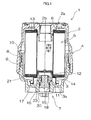
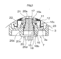
- the drain bolt 20 is screwed into the drain hole 15 of the cap 3 via the O-ring 23, and the drain hole 15 is sealed (refer to Fig. 2). Further, the oil flowing from the side of the internal combustion engine via the inflow passage 2a of the case 2 is filtrated by the filter element 5, and thereafter the filtrated oil is returned to the side of the internal combustion engine via the outflow passage 2b.
- the structure is not limited to the embodiment 2 mentioned above, and can be made as an embodiment which is variously modified within the scope of the present invention in correspondence to the object and the intended use.
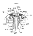
- the structure is made such that the oil is discharged from the lower end opening of the drain bolt 120 to the oil receiving plate or the like placed in the lower side of the drain bolt, however, the structure is not limited to this, and the structure may be made, for example, such that one end of an oil discharging hose (not shown) is connected to the connection portion 120e of the drain bolt 120 and the oil is discharged via the hose. Accordingly, it is possible to obtain the same performance and effects as those of the embodiment 1 mentioned above, and it is possible to prevent the oil from splashing at a time of discharging the oil.
Applications Claiming Priority (3)
| Application Number | Priority Date | Filing Date | Title |
|---|---|---|---|
| JP2002370445A JP2004195437A (ja) | 2002-12-20 | 2002-12-20 | 流体フィルタ及びそのドレン機構、並びに流体フィルタのドレン方法 |
| JP2003001419A JP2004209427A (ja) | 2003-01-07 | 2003-01-07 | 流体フィルタ及びそのドレン機構 |
| EP03029173A EP1430941B1 (de) | 2002-12-20 | 2003-12-18 | Flüssigkeitsfilter, Entleerungsvorrichtung für den Flüssigkeitsfilter und Entleerungsverfahren |
Related Parent Applications (1)
| Application Number | Title | Priority Date | Filing Date |
|---|---|---|---|
| EP03029173A Division EP1430941B1 (de) | 2002-12-20 | 2003-12-18 | Flüssigkeitsfilter, Entleerungsvorrichtung für den Flüssigkeitsfilter und Entleerungsverfahren |
Publications (1)
| Publication Number | Publication Date |
|---|---|
| EP1775005A1 true EP1775005A1 (de) | 2007-04-18 |
Family
ID=32396342
Family Applications (2)
| Application Number | Title | Priority Date | Filing Date |
|---|---|---|---|
| EP03029173A Expired - Lifetime EP1430941B1 (de) | 2002-12-20 | 2003-12-18 | Flüssigkeitsfilter, Entleerungsvorrichtung für den Flüssigkeitsfilter und Entleerungsverfahren |
| EP06124820A Withdrawn EP1775005A1 (de) | 2002-12-20 | 2003-12-18 | Flüssigkeitsfilter, zugehöriger Entleerungsmechanismus und Entleerungsverfahren für Flüssigkeitsfilter |
Family Applications Before (1)
| Application Number | Title | Priority Date | Filing Date |
|---|---|---|---|
| EP03029173A Expired - Lifetime EP1430941B1 (de) | 2002-12-20 | 2003-12-18 | Flüssigkeitsfilter, Entleerungsvorrichtung für den Flüssigkeitsfilter und Entleerungsverfahren |
Country Status (2)
| Country | Link |
|---|---|
| EP (2) | EP1430941B1 (de) |
| DE (1) | DE60311950T2 (de) |
Cited By (1)
| Publication number | Priority date | Publication date | Assignee | Title |
|---|---|---|---|---|
| US11213770B2 (en) | 2017-03-10 | 2022-01-04 | Mann+Hummel Gmbh | Filter element for a machine tool, machine tool, use, and exchange method |
Families Citing this family (2)
| Publication number | Priority date | Publication date | Assignee | Title |
|---|---|---|---|---|
| US8020580B2 (en) | 2008-07-07 | 2011-09-20 | Purolator Filters Na Llc | Drain pipe connector for fluid filters |
| DE112013005747B4 (de) | 2012-11-30 | 2019-08-22 | Mann+Hummel Gmbh | Filter, Filterelement, Filtergehäuse und Ablassvorrichtung eines Filters |
Citations (8)
| Publication number | Priority date | Publication date | Assignee | Title |
|---|---|---|---|---|
| US4440193A (en) * | 1981-11-23 | 1984-04-03 | Cummins Engine Company, Inc. | Valve assembly |
| US4470301A (en) * | 1982-09-22 | 1984-09-11 | Fram Corporation | Probe and drain assembly for fuel oil/water separator |
| US4477345A (en) * | 1983-01-10 | 1984-10-16 | Stant Inc. | Filter separator with heater |
| US4565629A (en) * | 1982-02-24 | 1986-01-21 | Parker-Hannifin Corporation | Filter assembly |
| JPS6368715A (ja) * | 1986-09-09 | 1988-03-28 | Nippon Denso Co Ltd | 自動車用ラジエ−タのドレ−ン装置 |
| US5226452A (en) * | 1991-01-31 | 1993-07-13 | Bendix Europe Services Technique | Drain plug for a hydraulic circuit |
| JPH09173716A (ja) * | 1995-12-27 | 1997-07-08 | Denso Corp | エレメント交換型フィルタ |
| JPH11104408A (ja) * | 1997-10-06 | 1999-04-20 | Tenekkusu:Kk | 液体処理用のフィルタ |
Family Cites Families (2)
| Publication number | Priority date | Publication date | Assignee | Title |
|---|---|---|---|---|
| DE3042969A1 (de) * | 1980-11-14 | 1982-07-01 | M.A.N. Maschinenfabrik Augsburg-Nürnberg AG, 8500 Nürnberg | Einrichtung zum ablassen von fluessigkeiten mittels einer loesbaren schraube |
| US5762130A (en) * | 1996-12-09 | 1998-06-09 | General Motors Corporation | Down flow, two pass radiator with air venting means |
-
2003
- 2003-12-18 EP EP03029173A patent/EP1430941B1/de not_active Expired - Lifetime
- 2003-12-18 EP EP06124820A patent/EP1775005A1/de not_active Withdrawn
- 2003-12-18 DE DE60311950T patent/DE60311950T2/de not_active Expired - Lifetime
Patent Citations (8)
| Publication number | Priority date | Publication date | Assignee | Title |
|---|---|---|---|---|
| US4440193A (en) * | 1981-11-23 | 1984-04-03 | Cummins Engine Company, Inc. | Valve assembly |
| US4565629A (en) * | 1982-02-24 | 1986-01-21 | Parker-Hannifin Corporation | Filter assembly |
| US4470301A (en) * | 1982-09-22 | 1984-09-11 | Fram Corporation | Probe and drain assembly for fuel oil/water separator |
| US4477345A (en) * | 1983-01-10 | 1984-10-16 | Stant Inc. | Filter separator with heater |
| JPS6368715A (ja) * | 1986-09-09 | 1988-03-28 | Nippon Denso Co Ltd | 自動車用ラジエ−タのドレ−ン装置 |
| US5226452A (en) * | 1991-01-31 | 1993-07-13 | Bendix Europe Services Technique | Drain plug for a hydraulic circuit |
| JPH09173716A (ja) * | 1995-12-27 | 1997-07-08 | Denso Corp | エレメント交換型フィルタ |
| JPH11104408A (ja) * | 1997-10-06 | 1999-04-20 | Tenekkusu:Kk | 液体処理用のフィルタ |
Non-Patent Citations (3)
| Title |
|---|
| PATENT ABSTRACTS OF JAPAN vol. 012, no. 292 (M - 729) 10 August 1988 (1988-08-10) * |
| PATENT ABSTRACTS OF JAPAN vol. 1997, no. 11 28 November 1997 (1997-11-28) * |
| PATENT ABSTRACTS OF JAPAN vol. 1999, no. 09 30 July 1999 (1999-07-30) * |
Cited By (1)
| Publication number | Priority date | Publication date | Assignee | Title |
|---|---|---|---|---|
| US11213770B2 (en) | 2017-03-10 | 2022-01-04 | Mann+Hummel Gmbh | Filter element for a machine tool, machine tool, use, and exchange method |
Also Published As
| Publication number | Publication date |
|---|---|
| DE60311950T2 (de) | 2007-10-31 |
| DE60311950D1 (de) | 2007-04-05 |
| EP1430941B1 (de) | 2007-02-21 |
| EP1430941A1 (de) | 2004-06-23 |
Similar Documents
| Publication | Publication Date | Title |
|---|---|---|
| EP0711196B1 (de) | Flüssigkeitsfilterpatrone mit auswechelbarem filterelement | |
| CN100355480C (zh) | 流体过滤器及其排流机构、排流用工具及排流方法 | |
| US5681461A (en) | Fluid filter having a reusable filter housing and central core and a replaceable coreless filter element | |
| US5695636A (en) | Fluid filter having a reusable filter housing and a replaceable filter element | |
| EP1419809A1 (de) | Filtrierungsvorrichtung mit Wechselfiltereinsatz und Entleerungsvorrichtung | |
| GB2145006A (en) | Filter assembly | |
| CA2845937C (en) | Enhanced filter support basket | |
| JP4887317B2 (ja) | オイルフィルタ | |
| US8020580B2 (en) | Drain pipe connector for fluid filters | |
| US5817232A (en) | Rebuildable spin-on filters | |
| JP5368079B2 (ja) | オイルフィルタ | |
| US7150828B2 (en) | Fluid filter having drain structure and drain tool | |
| US20170197162A1 (en) | Filter cartridge having separable filter components | |
| EP1430941B1 (de) | Flüssigkeitsfilter, Entleerungsvorrichtung für den Flüssigkeitsfilter und Entleerungsverfahren | |
| JP4376615B2 (ja) | ケース共回り防止機構を有するエレメント交換型オイルフィルタ | |
| JP4927772B2 (ja) | オイルフィルタ | |
| JP2004195437A (ja) | 流体フィルタ及びそのドレン機構、並びに流体フィルタのドレン方法 | |
| US20060091062A1 (en) | Filtering device | |
| JP3341642B2 (ja) | フィルタ装置 | |
| JP2009214005A (ja) | オイルフィルタ | |
| JPH08170782A (ja) | 自動車エンジン用のオイル抜き栓及びオイル抜取り装置 | |
| JP4366271B2 (ja) | 作動油タンクのサクションフィルタ固定装置 | |
| JP2004209427A (ja) | 流体フィルタ及びそのドレン機構 | |
| JP4725553B2 (ja) | 流体フィルタのドレン機構 | |
| JP4467400B2 (ja) | オイルフィルター保護金具及び該オイルフィルター保護金具を備える舶用減速逆転機 |
Legal Events
| Date | Code | Title | Description |
|---|---|---|---|
| PUAI | Public reference made under article 153(3) epc to a published international application that has entered the european phase |
Free format text: ORIGINAL CODE: 0009012 |
|
| AC | Divisional application: reference to earlier application |
Ref document number: 1430941 Country of ref document: EP Kind code of ref document: P |
|
| AK | Designated contracting states |
Kind code of ref document: A1 Designated state(s): DE FR IT |
|
| 17P | Request for examination filed |
Effective date: 20070619 |
|
| AKX | Designation fees paid |
Designated state(s): DE FR IT |
|
| STAA | Information on the status of an ep patent application or granted ep patent |
Free format text: STATUS: THE APPLICATION IS DEEMED TO BE WITHDRAWN |
|
| 18D | Application deemed to be withdrawn |
Effective date: 20090701 |