EP1774911B1 - Medizinisches Bildgebungssystem und Kollisionsschutzverfahren - Google Patents
Medizinisches Bildgebungssystem und Kollisionsschutzverfahren Download PDFInfo
- Publication number
- EP1774911B1 EP1774911B1 EP06121313A EP06121313A EP1774911B1 EP 1774911 B1 EP1774911 B1 EP 1774911B1 EP 06121313 A EP06121313 A EP 06121313A EP 06121313 A EP06121313 A EP 06121313A EP 1774911 B1 EP1774911 B1 EP 1774911B1
- Authority
- EP
- European Patent Office
- Prior art keywords
- patient
- sensor
- imaging system
- moveable part
- control device
- Prior art date
- Legal status (The legal status is an assumption and is not a legal conclusion. Google has not performed a legal analysis and makes no representation as to the accuracy of the status listed.)
- Not-in-force
Links
- 238000000034 method Methods 0.000 title claims abstract description 16
- 238000002059 diagnostic imaging Methods 0.000 title claims description 12
- 230000004224 protection Effects 0.000 title abstract description 12
- 238000003384 imaging method Methods 0.000 claims abstract description 28
- 230000003287 optical effect Effects 0.000 claims description 7
- 238000013459 approach Methods 0.000 claims description 6
- 230000005672 electromagnetic field Effects 0.000 claims description 5
- 238000001514 detection method Methods 0.000 claims description 2
- 238000002604 ultrasonography Methods 0.000 claims description 2
- 238000002583 angiography Methods 0.000 description 3
- 238000002601 radiography Methods 0.000 description 2
- 230000001133 acceleration Effects 0.000 description 1
- 230000002411 adverse Effects 0.000 description 1
- 239000003795 chemical substances by application Substances 0.000 description 1
- 238000002591 computed tomography Methods 0.000 description 1
- 230000001419 dependent effect Effects 0.000 description 1
- 238000002405 diagnostic procedure Methods 0.000 description 1
- 230000000694 effects Effects 0.000 description 1
- 210000004072 lung Anatomy 0.000 description 1
- 238000009607 mammography Methods 0.000 description 1
- 238000009206 nuclear medicine Methods 0.000 description 1
- 230000009979 protective mechanism Effects 0.000 description 1
- 230000005855 radiation Effects 0.000 description 1
- 230000035484 reaction time Effects 0.000 description 1
- 230000007704 transition Effects 0.000 description 1
Images

Classifications
-
- A—HUMAN NECESSITIES
- A61—MEDICAL OR VETERINARY SCIENCE; HYGIENE
- A61B—DIAGNOSIS; SURGERY; IDENTIFICATION
- A61B6/00—Apparatus or devices for radiation diagnosis; Apparatus or devices for radiation diagnosis combined with radiation therapy equipment
- A61B6/58—Testing, adjusting or calibrating thereof
- A61B6/589—Setting distance between source unit and patient
-
- A—HUMAN NECESSITIES
- A61—MEDICAL OR VETERINARY SCIENCE; HYGIENE
- A61B—DIAGNOSIS; SURGERY; IDENTIFICATION
- A61B6/00—Apparatus or devices for radiation diagnosis; Apparatus or devices for radiation diagnosis combined with radiation therapy equipment
- A61B6/10—Safety means specially adapted therefor
- A61B6/102—Protection against mechanical damage, e.g. anti-collision devices
-
- A—HUMAN NECESSITIES
- A61—MEDICAL OR VETERINARY SCIENCE; HYGIENE
- A61B—DIAGNOSIS; SURGERY; IDENTIFICATION
- A61B6/00—Apparatus or devices for radiation diagnosis; Apparatus or devices for radiation diagnosis combined with radiation therapy equipment
- A61B6/44—Constructional features of apparatus for radiation diagnosis
- A61B6/4429—Constructional features of apparatus for radiation diagnosis related to the mounting of source units and detector units
- A61B6/4452—Constructional features of apparatus for radiation diagnosis related to the mounting of source units and detector units the source unit and the detector unit being able to move relative to each other
-
- A—HUMAN NECESSITIES
- A61—MEDICAL OR VETERINARY SCIENCE; HYGIENE
- A61B—DIAGNOSIS; SURGERY; IDENTIFICATION
- A61B6/00—Apparatus or devices for radiation diagnosis; Apparatus or devices for radiation diagnosis combined with radiation therapy equipment
- A61B6/44—Constructional features of apparatus for radiation diagnosis
- A61B6/4429—Constructional features of apparatus for radiation diagnosis related to the mounting of source units and detector units
- A61B6/4458—Constructional features of apparatus for radiation diagnosis related to the mounting of source units and detector units the source unit or the detector unit being attached to robotic arms
-
- A—HUMAN NECESSITIES
- A61—MEDICAL OR VETERINARY SCIENCE; HYGIENE
- A61B—DIAGNOSIS; SURGERY; IDENTIFICATION
- A61B6/00—Apparatus or devices for radiation diagnosis; Apparatus or devices for radiation diagnosis combined with radiation therapy equipment
- A61B6/44—Constructional features of apparatus for radiation diagnosis
- A61B6/4429—Constructional features of apparatus for radiation diagnosis related to the mounting of source units and detector units
- A61B6/4464—Constructional features of apparatus for radiation diagnosis related to the mounting of source units and detector units the source unit or the detector unit being mounted to ceiling
-
- A—HUMAN NECESSITIES
- A61—MEDICAL OR VETERINARY SCIENCE; HYGIENE
- A61B—DIAGNOSIS; SURGERY; IDENTIFICATION
- A61B6/00—Apparatus or devices for radiation diagnosis; Apparatus or devices for radiation diagnosis combined with radiation therapy equipment
- A61B6/54—Control of apparatus or devices for radiation diagnosis
- A61B6/547—Control of apparatus or devices for radiation diagnosis involving tracking of position of the device or parts of the device
-
- A—HUMAN NECESSITIES
- A61—MEDICAL OR VETERINARY SCIENCE; HYGIENE
- A61B—DIAGNOSIS; SURGERY; IDENTIFICATION
- A61B6/00—Apparatus or devices for radiation diagnosis; Apparatus or devices for radiation diagnosis combined with radiation therapy equipment
- A61B6/54—Control of apparatus or devices for radiation diagnosis
- A61B6/548—Remote control of the apparatus or devices
-
- A—HUMAN NECESSITIES
- A61—MEDICAL OR VETERINARY SCIENCE; HYGIENE
- A61B—DIAGNOSIS; SURGERY; IDENTIFICATION
- A61B5/00—Measuring for diagnostic purposes; Identification of persons
- A61B5/0059—Measuring for diagnostic purposes; Identification of persons using light, e.g. diagnosis by transillumination, diascopy, fluorescence
- A61B5/0062—Arrangements for scanning
- A61B5/0064—Body surface scanning
-
- A—HUMAN NECESSITIES
- A61—MEDICAL OR VETERINARY SCIENCE; HYGIENE
- A61B—DIAGNOSIS; SURGERY; IDENTIFICATION
- A61B5/00—Measuring for diagnostic purposes; Identification of persons
- A61B5/103—Measuring devices for testing the shape, pattern, colour, size or movement of the body or parts thereof, for diagnostic purposes
- A61B5/11—Measuring movement of the entire body or parts thereof, e.g. head or hand tremor or mobility of a limb
- A61B5/1113—Local tracking of patients, e.g. in a hospital or private home
- A61B5/1114—Tracking parts of the body
-
- A—HUMAN NECESSITIES
- A61—MEDICAL OR VETERINARY SCIENCE; HYGIENE
- A61B—DIAGNOSIS; SURGERY; IDENTIFICATION
- A61B6/00—Apparatus or devices for radiation diagnosis; Apparatus or devices for radiation diagnosis combined with radiation therapy equipment
- A61B6/44—Constructional features of apparatus for radiation diagnosis
- A61B6/4429—Constructional features of apparatus for radiation diagnosis related to the mounting of source units and detector units
- A61B6/4435—Constructional features of apparatus for radiation diagnosis related to the mounting of source units and detector units the source unit and the detector unit being coupled by a rigid structure
- A61B6/4441—Constructional features of apparatus for radiation diagnosis related to the mounting of source units and detector units the source unit and the detector unit being coupled by a rigid structure the rigid structure being a C-arm or U-arm
Definitions
- the invention relates to a medical imaging system having a patient-traversable part, and more particularly to a system in which movement of the movable part is controlled by a controller which stops or slows the movement as the part approaches the patient, i. falls below a predeterminable minimum distance to certain surface areas of the patient or approaches.
- X-ray systems are known in the art, which are characterized by a great flexibility in the movements of the image recording devices to the patient.
- these movable parts are, in particular, the X-ray detector and the X-ray tube.
- C-arm X-ray systems in which X-ray tube and detector are respectively mounted on opposite arms of a C-arm, which can be moved around the patient, so as to allow X-ray recordings from any projection directions.
- Digital imaging methods are now playing a crucial role in medical diagnostics. While digital techniques have been used in diagnostic procedures such as computed tomography, magnetic resonance, ultrasound, and nuclear medicine techniques from the beginning, at present, particularly with the aid of flat panel detectors, "conventional" X-ray techniques such as radiography, mammography, angiography or the cardiology of the transition to digital imaging to a high degree (see, for example Spahn et al. "Digital X-ray detectors in X-ray diagnostics", Radiology 43 (2003), pages 340 to 350 ).
- AXIOM Artis z. B. defines a patient enveloping protection zone. If a C-arm approaches this protection zone, it slows down considerably to avoid the risk of a collision.
- This protection zone is the same for all patients and has approximately the shape of an ellipsoid arranged above the patient couch. Therefore, especially in thin patients, this protection zone is often far away from the actual patient surface. Therefore, it often takes an unnecessarily long time to approach a certain angulation of the C-arm.
- the devices of the company Philips are partly on the C-arms capacitive sensors, which detect the proximity of the patient and then slow down the movement of the C-arm.
- these sensors have only a short range, so that also here the movement of the C-arm should be slowed down when entering an assumed protection zone, otherwise it comes with fast movements to collision.
- both systems feature mechanical feedbacks that immediately stop the movement of the movable parts in the event of an actual patient contact (cf. EP 0 395 352 A1 which indicates a decoupling of the arm motor from the power supply in the event of a collision).
- a disadvantage of the mechanical execution of collision protection or the calculation of a protection zone is that the method either relies on contact or requires extensive computation, so that the increasingly faster movements of the movable part, the reaction time, which is thereby becoming shorter, often insufficient in order to actually prevent a collision, or it will then increasingly higher braking pulses needed to intercept the movable part.
- This in turn requires more stable mechanics and more powerful motors or braking systems, which in turn increases the cost and mass of the systems, ultimately again the brake pulses and the movement of the movable part is adversely affected.
- a medical imaging system having the features of the first part of claim 1 is made DE-A-198 55 213 known. From this it follows - mutatis mutandis - a Kollisionstikverfahen.
- the object of the invention has been found to provide a medical imaging system with a faster, more accurate and simpler collision protection system, as well as a corresponding collision protection method.
- the medical imaging system comprising a patient-displaceable part, such as a C-arm or a robotic arm, is provided with at least one sensor which detects the surface of the patient or other object, while a control device which controls the movement of the patient movable part regulates due to the calculated distances between the movable part and the surface of the patient or another object according to the movement of the movable part controls, that is, for example, stops or slows down when the part of the patient or another object approaches or This touches.
- a patient-displaceable part such as a C-arm or a robotic arm
- the control device calculates the distances between the movable part and the surface of the patient or another object that lies in the travel path and regulates the movement accordingly.
- the at least one sensor transmits the positions of individual surface areas of the patient or of another object to the control device, at the same time the control device receives the position of the movable part from a second sensor, which detects the position of the movable part and transmits it to the control device.
- the control device can determine the distances between the movable part and corresponding surface areas from the positions and regulate the speed or the travel direction of the movable part accordingly.
- the sensor for determining the surface areas may be an ultrasonic sensor, an optical sensor or an electromagnetic sensor.
- Such sensors are advantageous for particularly fast movements, such as in 3D acquisition.
- the sensors are integrated in the detector housing of the imaging device or in or on the X-ray tube or other exposed areas of the movable part.
- the second sensor can likewise be an electromagnetic sensor which comprises a first sensor part which generates an electromagnetic field in the space around the patient or around the medical imaging system and from a second sensor part, the is attached to the movable part and detects the position of the movable part in the electromagnetic field.
- the second sensor may also be an optical, an acceleration or an ultrasonic sensor, which detects the position of the movable part.
- the imaging system is an X-ray system
- the movable part is an X-ray detector or an X-ray tube.
- the imaging system is a C-X-ray arc system in which the X-ray detector and X-ray tube are attached to a large C-arm that is movable about the patient.
- a plurality of (collision) sensors are fastened at different points of the movable part.
- the coordinate system of the imaging system and that of the sensor or sensors are spatially calibrated to each other. This facilitates the calculation of the distances between the movable part and the surface areas of the external object, such as the surface of the patient.
- the imaging system may also be configured to create a 3D model of the patient from the captured surface of the patient and register it with the coordinate system of the imaging system.
- the control device can exactly predetermine the movement of the movable part.
- this 3D model is updated at regular intervals to avoid that the patient's movements are preceded by a wrong 3D model when the patient moves. All calculations can also be performed by an external processing unit, which delivers the results to the controller.
- the present invention further relates to a collision avoidance method for a medical imaging system having a patient-traversable part for preventing a collision of the traveling part with an external object such as the patient, the movement of the traveling part depending on the distance to the patient is controllable by a control device by the surface of the patient is detected by at least one sensor and the control device based on the calculated distances between the movable part and the surface of the object according to the movement of the movable part controls.
- the positions of individual surface regions of the object are detected by the at least one sensor and transmitted to the control device.
- the positions of the movable part are continuously detected by means of a second sensor and forwarded to the control device.
- the control device can then determine the distances between the movable part and the corresponding surface areas of the patient or another object and regulate the speed or the travel direction of the movable part accordingly.
- the detection of the surface is made possible by an optical sensor, wherein the coordinate system of the imaging system and that of the optical sensor are calibrated to each other before the acquisition of corresponding image data.
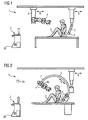
- Fig. 1 shows a medical imaging system 1 with a schematically illustrated patient 3 sitting on a table.
- a 3D tripod for the X-ray source shown on the left
- a 3D tripod for the X-ray detector Positioned on both sides of the patient, so that, for example, transillumination of the patient's lungs can be made.
- both tripods can be moved in the direction of movement B or perpendicular thereto.
- the X-ray detector can be rotated.
- This movable part 5 is provided with a sensor 4, just as the X-ray source is also equipped with a sensor 4.
- Fig. 2 shows an X-ray C-arm system, for example, for cardiology or angiography, with sensors 4 at correspondingly exposed locations of the X-ray source and the X-ray detector.
- the C-arm can also be moved in the direction of movement B, as the C-arm can rotate around the patient 3.
- the movable part 5 is in this case the C-arm 7, which rotates about the patient 3. Again, the distance data of the sensors 4 are transmitted to a control device 2.
- a second sensor 8 detects the respective position of the C-arm 7 by attaching a second part 8b of the second sensor 8 to the X-ray source and thus transmits corresponding position data to the first part 8a of the second sensor 8 or directly to the control device 2 ,
- Such position detectors are known in the art, for example, an electromagnetic system is suitable here, wherein the first sensor part 8a builds up an electromagnetic field which is correspondingly detected in the second sensor part 8b when the movable part 5 moves, so that position changes can be detected.
- Fig. 3 shows a robot arm system according to the invention with different rotating arms 6, the different rotational movements B perform can.
- the rotational movements B are carried out in all directions, in which the individual rotating arms 6 are connected by ball joints, so that the movable part is movable in all six directions of movement.
- sensors 4 are located at the exposed point of the movable part 5 and measure the distance to the patient 3. These data are also forwarded to the control device by wire or wirelessly.
- the control device 2 controls or regulates the individual robot arms 6 in accordance with the distance data of the sensors 4.
Landscapes
- Health & Medical Sciences (AREA)
- Life Sciences & Earth Sciences (AREA)
- Engineering & Computer Science (AREA)
- Medical Informatics (AREA)
- Heart & Thoracic Surgery (AREA)
- Molecular Biology (AREA)
- Biophysics (AREA)
- Nuclear Medicine, Radiotherapy & Molecular Imaging (AREA)
- Optics & Photonics (AREA)
- Pathology (AREA)
- Radiology & Medical Imaging (AREA)
- Biomedical Technology (AREA)
- Physics & Mathematics (AREA)
- High Energy & Nuclear Physics (AREA)
- Surgery (AREA)
- Animal Behavior & Ethology (AREA)
- General Health & Medical Sciences (AREA)
- Public Health (AREA)
- Veterinary Medicine (AREA)
- Automation & Control Theory (AREA)
- Robotics (AREA)
- Apparatus For Radiation Diagnosis (AREA)
- Manipulator (AREA)
- Ultra Sonic Daignosis Equipment (AREA)
Description
- Die Erfindung betrifft ein medizinisches Bildgebungssystem mit einem um einen Patienten verfahrbaren Teil und insbesondere ein System, bei welchem die Bewegung des verfahrbaren Teils durch ein Regelgerät geregelt wird, welches die Bewegung stoppt oder verlangsamt, wenn sich das Teil dem Patienten nähert, d.h. einen vorbestimmbaren Mindestabstand zu bestimmten Oberflächenbereichen des Patienten unterschreitet oder sich diesen nähert.
- Im Stand der Technik sind medizinische Bildgebungssysteme, insbesondere Röntgensysteme bekannt, die sich durch eine große Flexibilität in den Bewegungen der Bildaufnahmegeräte um den Patienten auszeichnen. Im Falle eines Röntgensystems handelt es sich bei diesen verfahrbaren Teilen insbesondere um den Röntgendetektor und die Röntgenröhre. Großer Beliebtheit erfreuen sich insbesondere die so genannten C-Bogen-Röntgensysteme, bei welchen Röntgenröhre- und Detektor jeweils an einander gegenüberliegenden Armen eines C-Bogens befestigt sind, welcher beliebig um den Patienten verfahrbar ist, um so Röntgenaufnahmen aus beliebigen Projektionsrichtungen zu ermöglichen. Durch Variation des Abstandes zwischen Röntgendetektor und Patient kann darüber hinaus die Vergrößerung verändert und die bildverrauschende Streustrahlung minimiert werden. Solche Systeme, wie z. B. das AXIOM Artis der Siemens AG, werden insbesondere als Angiographiesysteme benutzt. Zunehmend werden mit solchen Röntgengeräten auch quasi-tomographische 3D-Bilder erzeugt, bei denen der C-Bogen um ca. 180° um den Patienten verfahren wird. Bei einem solchen Durchlauf, der auch mit "DynaRun" bezeichnet wird, werden die beweglichen Teile zum Teil mit erheblicher Geschwindigkeit um den Patienten rotiert. Ein Problem derartiger Bildgebungssysteme mit verfahrbaren Teilen liegt darin, dass eine Kollision der verfahrbaren Teile mit dem Patienten möglich ist. Um Gefährdungen für den Patienten auszuschließen, müssen daher Schutzmechanismen eingeführt werden.
- Digitale Bildgebungsverfahren spielen inzwischen eine entscheidende Rolle in der medizinischen Diagnostik. Während in diagnostischen Verfahren, wie zum Beispiel der Computertomographie, der Magnetresonanz, dem Ultraschall und Verfahren der Nuklearmedizin digitale Techniken von Beginn an eingesetzt wurden, findet derzeit insbesondere mit Hilfe der Flachdetektoren in "konventionellen" Röntgenverfahren, wie der Radiographie, der Mammographie, der Angiographie oder auch der Kardiologie der Übergang zur digitalen Bildgebung in hohem Maße statt (siehe beispielsweise Spahn et al. "Digitale Röntgen-Detektoren in der Röntgendiagnostik", Radiologie 43 (2003), Seiten 340 bis 350).
- Diese neuen Verfahren erfordern immer schnellere Akquisitionen bzw. eine immer größere Anzahl von Bildern für eine dreidimensionale Bild-Akquisition, wobei beispielsweise bei einer gewöhnlichen Projektions-Radiographie inzwischen auch Roboterarme eingesetzt werden, die durch die Anwahl eines Organprogramms angesteuert werden können und selbstständig in eine neue Position verfahren. Auch hier besteht ein Interesse, das Verfahren möglichst schnell durchzuführen, um den Ablauf im Krankenhaus zu beschleunigen.
- Auch hier besteht die Gefahr, dass eine Kollision des verfahrbaren Teils, wie z.B. des Roboterarms, mit dem Patienten möglich ist. Insbesondere bei schnellen Bewegungen von mechanischen Tragarmen besteht grundsätzlich die Gefahr einer Kollision zwischen diesem Tragarm und dem Patienten oder dem Tragarm und einer anderen mechanischen Komponente, wie beispielsweise dem Tisch, einem zweiten Tragarm oder anderen medizinischen Geräten. Dabei sind verschiedene Vorrichtungen und Verfahren bekannt, um eine Kollision zu vermeiden oder um die Auswirkung einer Kollision abzuschwächen:
- Bei dem oben genannten System AXIOM Artis wird z. B. eine den Patienten umhüllende Schutzzone definiert. Nähert sich ein C-Arm an diese Schutzzone an, wird er deutlich verlangsamt, um die Gefahr einer Kollision zu vermeiden. Diese Schutzzone ist für alle Patienten gleich und hat angenähert die Form eines über der Patientenliege angeordneten Ellipsoids. Insbesondere bei dünnen Patienten liegt diese Schutzzone daher oft weit entfernt von der tatsächlichen Patientenoberfläche. Daher dauert es oft unnötig lange, um eine bestimmte Angulation des C-Bogens anzufahren.
- Bei den Geräten der Firma Philips befinden sich teilweise an den C-Armen kapazitive Sensoren, welche die Nähe des Patienten detektieren und daraufhin die Bewegung des C-Arms verlangsamen. Diese Sensoren haben jedoch nur eine geringe Reichweite, so dass auch hier die Bewegung des C-Bogens bei Eintritt in eine angenommene Schutzzone verlangsamt werden sollte, da es sonst bei schnellen Bewegungen zur Kollision kommt.
- Als letzte Sicherheit weisen beide Systeme mechanische Rückmelder auf, die bei einem tatsächlichen Patientenkontakt sofort die Bewegung der verfahrbaren Teile stoppen (vgl. auch
EP 0 395 352 A1 , die bei Kollision eine Entkopplung des Arm-Motors von der Stromversorgung offenbart). - Ein Nachteil der mechanischen Ausführung eines Kollisionsschutzes oder der Berechnung einer Schutzzone ist es, dass das Verfahren entweder auf Kontakt beruht oder umfangreiche Rechenarbeiten erfordert, so dass bei den zunehmend schneller werdenden Bewegungen des verfahrbaren Teils die Reaktionszeit, die dadurch immer kürzer wird, oft nicht ausreicht, um eine Kollision tatsächlich zu verhindern, bzw. es werden dann zunehmend höhere Bremsimpulse nötig, um das verfahrbare Teil abzufangen. Dies erfordert wiederum stabilere Mechaniken und leistungsfähigere Motoren bzw. Bremssysteme, was wiederum die Kosten und die Masse der Systeme erhöht, wodurch letztendlich erneut die Bremsimpulse und der Bewegungsablauf des verfahrbaren Teils negativ beeinflusst wird.
- Ein medizinisches Bildgebungssystem mit den Merkmalen des ersten Teils von Anspruch 1 ist aus
DE-A-198 55 213 bekannt. Hieraus folgt - mutatis mutandis- ein Kollisionsschutzverfahen. - Die Erfindung hat sich die Aufgabe gestellt, ein medizinisches Bildgebungssystem mit einem schnelleren, genaueren und einfacheren Kollisionsschutzsystem, sowie ein entsprechendes Kollisionsschutzverfahren, bereit zu stellen.
- Diese Aufgabe löst die Erfindung mit den kennzeichnenden Merkmalen der Ansprüche 1 und 10. Bevorzugte Ausführungsformen des erfindungsgemäßen Bildgebungssystems und Kollisionsschutzverfahren sind in den jeweils abhängigen Ansprüchen angegeben.
- Erfindungsgemäß wird das medizinische Bildgebungssystem, das ein relativ zum Patienten verfahrbares Teil, wie beispielsweise einen C-Bogen oder einen Roboterarm aufweist, mit mindestens einem Sensor ausgestattet, der die Oberfläche des Patienten oder eines anderen Objekts erfasst, während ein Regelgerät, das die Bewegung des verfahrbaren Teils regelt, auf Grund der berechneten Abstände zwischen dem verfahrbaren Teil und der Oberfläche des Patienten oder eines anderen Objekts entsprechend die Bewegung des verfahrbaren Teils regelt, das heißt, beispielsweise stoppt oder verlangsamt, wenn sich das Teil dem Patienten oder einem anderen Objekt nähert bzw. diese berührt.
- Das Regelgerät berechnet aus der erfassten Oberfläche des Patienten die Abstände des verfahrbaren Teils zur Oberfläche des Patienten oder eines anderen Objekts, das im Verfahrweg liegt und regelt entsprechend die Bewegung. Der mindestens eine Sensor übermittelt hierfür die Positionen einzelner Oberflächenbereiche des Patienten oder eines anderen Objekts an das Regelgerät, gleichzeitig erhält das Regelgerät die Position des verfahrbaren Teils von einem zweiten Sensor, der die Position des verfahrbaren Teils detektiert und an das Regelgerät übermittelt. Im Anschluss daran kann das Regelgerät aus den Positionen die Abstände zwischen dem verfahrbaren Teil und entsprechenden Oberflächenbereichen ermitteln und die Geschwindigkeit bzw. die Verfahrrichtung des verfahrbaren Teils entsprechend regeln.
- Der Sensor zur Ermittlung der Oberflächenbereiche kann ein Ultraschall-Sensor, ein optischer Sensor oder ein elektromagnetischer Sensor sein. Insbesondere werden keine auf Kontakt basierenden Sensoren, wie im Stand der Technik eingesetzt, sondern Sensoren, die bereits auf Distanz eine Annäherung zwischen einer Sensor-bestückten Systemkomponente, wie beispielsweise dem verfahrbaren Teil und externen Objekten, wie dem Patienten orten und angeben können. Solche Sensoren sind für besonders schnelle Bewegungen, wie beispielsweise bei der 3D-Akquisition, vorteilhaft.
- Erfindungsgemäß sind die Sensoren im Detektorgehäuse des Bildgebungsgeräts oder in bzw. an der Röntgenröhre oder anderen exponierten Bereichen des verfahrbaren Teils integriert.
- Der zweite Sensor kann - nach einer weiteren vorteilhaften Ausführungsform der Erfindung - ebenfalls ein elektromagnetischer Sensor sein, der aus einem ersten Sensorteil besteht, das ein elektromagnetisches Feld im Raum um den Patienten bzw. um das medizinische Bildgebungssystem herum generiert und aus einem zweiten Sensorteil, das am verfahrbaren Teil angebracht ist und die Position des verfahrbaren Teils im elektromagnetischen Feld detektiert. Wahlweise kann der zweite Sensor aber auch ein optischer, ein Beschleunigungs- oder ein Ultraschall-Sensor sein, der die Position des verfahrbaren Teils detektiert.
- Mit Vorteil ist das Bildgebungssystem ein Röntgensystem, und das verfahrbare Teil ist ein Röntgendetektor oder eine Röntgenröhre. Insbesondere ist das Bildgebungssystem ein C-Röntgenbogen-System, bei welchem der Röntgendetektor und die Röntgenröhre an einem großen C-Bogen befestigt sind, der um den Patienten verfahrbar ist. Dabei werden nach einer weiteren vorteilhaften Ausführungsform der Erfindung mehrere (Kollisions-)Sensoren an verschiedenen Stellen des verfahrbaren Teils befestigt.
- Mit Vorteil ist das Koordinatensystem des Bildgebungssystems und das des Sensors oder der Sensoren räumlich zueinander kalibriert. Dies erleichtert dem Regelgerät die Berechnung der Abstände zwischen dem verfahrbaren Teil und den Oberflächenbereichen des externen Objekts, wie beispielsweise der Oberfläche des Patienten. Darüber hinaus kann das Bildgebungssystem auch dazu ausgelegt sein, aus der erfassten Oberfläche des Patienten ein 3D-Modell des Patienten zu erstellen und dieses mit dem Koordinatensystem des Bildgebungssystems zu registrieren. In diesem Fall kann das Regelgerät die Bewegung des verfahrbaren Teils exakt vorherbestimmen. Mit Vorteil wird dieses 3D-Modell in regelmäßigen Abständen aktualisiert, um zu vermeiden, dass bei Bewegungen des Patienten den Vorausberechnungen des Regelgeräts ein falsches 3D-Modell zugrunde liegt. Alle Berechnungen können auch von einer externen Recheneinheit durchgeführt werden, die die Ergebnisse ans Regelgerät liefert.
- Die vorliegende Erfindung betrifft darüber hinaus ein Kollisionsschutzverfahren für ein medizinisches Bildgebungssystem, mit einem um einen Patienten verfahrbaren Teil, zur Verhinderung einer Kollision des verfahrbaren Teils mit einem externen Objekt, wie beispielsweise dem Patienten, wobei die Bewegung des verfahrbaren Teils in Abhängigkeit vom Abstand zum Patienten durch ein Regelgerät regelbar ist, indem die Oberfläche des Patienten durch mindestens einen Sensor erfasst wird und das Regelgerät auf Grund der berechneten Abstände zwischen dem verfahrbaren Teil und der Oberfläche des Objekts entsprechend die Bewegung des verfahrbaren Teils regelt.
- In dem Verfahren werden die Positionen einzelner Oberflächenbereiche des Objekts durch den mindestens einen Sensor detektiert und an das Regelgerät übermittelt. Die Positionen des verfahrbaren Teils werden fortlaufend mittels eines zweiten Sensors detektiert und an das Regelgerät weitergeleitet. Das Regelgerät kann dann die Abstände zwischen dem verfahrbaren Teil und den entsprechenden Oberflächenbereichen des Patienten bzw. eines anderen Objekts ermitteln und die Geschwindigkeit bzw. die Verfahrrichtung des verfahrbaren Teils entsprechend regeln. Nach einer bevorzugten Ausführungsform der Erfindung wird die Erfassung der Oberfläche durch einen optischen Sensor ermöglicht, wobei des Koordinatensystem des Bildgebungssystems und das des optischen Sensors vor der Aufnahme von entsprechenden Bilddaten zueinander kalibriert werden.
- Eine vorteilhafte Ausführungsform der Erfindung wird an Hand der beiliegenden Zeichnungen näher erläutert. Dabei zeigen:
- Fig. 1
- ein medizinisches Bildgebungssystem mit Kollisionssensoren an exponierten Stellen der verfahrbaren Teile,
- Fig. 2
- ein Röntgen-C-Bogen-System mit entsprechenden Kollisionssensoren , und
- Fig. 3
- ein Roboterarm-System nach der vorliegenden Erfindung mit entsprechenden Kollisionssensoren an exponierten Stellen der verfahrbaren Arme.
-
Fig. 1 zeigt ein medizinisches Bildgebungssystem 1 mit einem schematisch dargestellten Patienten 3, der auf einem Tisch sitzt. Ein 3D-Stativ für den Röntgenstrahler (links im Bild dargestellt) und ein 3D-Stativ für den Röntgendetektor werden auf beiden Seiten des Patienten positioniert, sodass beispielsweise Durchleuchtungsaufnahmen der Lunge des Patienten angefertigt werden können. Zur Justierung können beide Stative in der Bewegungsrichtung B oder senkrecht dazu verfahren werden. Darüber hinaus kann der Röntgendetektor gedreht werden. Dieses verfahrbare Teil 5 wird mit einem Sensor 4 versehen, ebenso wie der Röntgenstrahler auch mit einem Sensor 4 ausgestattet wird. Durch die zwei Sensoren 4 können entsprechende Abstände zwischen den verfahrbaren Teilen 5 und der Oberfläche des Patienten 3 detektiert und an ein Regelgerät 2 übertragen werden, das die Bewegung B der verfahrbaren Teile 5 regelt. -
Fig. 2 zeigt ein Röntgen-C-Bogen-System, beispielsweise für die Kardiologie oder auch Angiographie, mit Sensoren 4 an entsprechend exponierten Stellen des Röntgenstrahlers und des Röntgendetektors. Der C-Bogen kann ebenfalls in Bewegungsrichtung B bewegt werden, wie der C-Bogen um den Patienten 3 rotieren kann. Das verfahrbare Teil 5 ist in diesem Fall der C-Bogen 7, der um den Patienten 3 rotiert. Auch hier werden die Abstandsdaten der Sensoren 4 an ein Regelgerät 2 übertragen. - Nach der Erfindung detektiert ein zweiter Sensor 8 die jeweilige Position des C-Bogens 7, indem ein zweiter Teil 8b des zweiten Sensors 8 am Röntgenstrahler angebracht wird und so entsprechende Positionsdaten an den ersten Teil 8a des zweiten Sensors 8 oder direkt an das Regelgerät 2 übermittelt. Derartige Positionsdetektoren sind im Stand der Technik bekannt, beispielsweise eignet sich hier ein elektromagnetisches System, wobei der erste Sensorteil 8a ein elektromagnetisches Feld aufbaut, das im zweiten Sensorteil 8b bei Bewegung des verfahrbaren Teils 5 entsprechend detektiert wird, so dass Positionsänderungen festgestellt werden können.
-
Fig. 3 zeigt ein erfindungsgemäßes Roboterarm-System mit verschiedenen Dreharmen 6, die verschiedene Drehbewegungen B ausführen können. Die Drehbewegungen B werden dabei in allen Richtungen ausgeführt, in dem die einzelnen Dreharme 6 durch Kugelgelenke verbunden sind, so dass das verfahrbare Teil in allen sechs Bewegungsrichtungen verfahrbar ist. Auch hier befinden sich Sensoren 4 an exponierter Stelle des verfahrbaren Teils 5 und messen die Entfernung zum Patienten 3. Diese Daten werden ebenfalls an das Regelgerät drahtgebunden oder drahtlos weitergeleitet. Das Regelgerät 2 steuert bzw. regelt die einzelnen Roboterarme 6 entsprechend den Abstandsdaten der Sensoren 4.
Claims (11)
- Medizinisches Bildgebungssystem (1) einem Bildgebungsgerät und einer Röntgenröhre und mit einem relativ zum Patienten (3) verfahrbaren Teil (5), welches sich an einem Roboterarm-System mit verschiedenen Dreharmen (6), die verschiedene Drehbewegungen(B)ausführen können, befindet, wobei die Bewegung des verfahrbaren Teils (5) durch ein Regelgerät (2) gesteuert wird, welches die Bewegung stoppt oder verlangsamt, wenn das Teil (5) den Patienten oder ein anderes Objekt berührt oder sich annähert, dadurch gekennzeichnet, dass
mindestens ein Sensor (4) die Oberfläche des Patienten (3) oder des anderen Objekts erfasst und der mindestens eine Sensor (4) die Positionen einzelner Oberflächenbereiche des Patienten oder des anderen Objekts an das Regelgerät (2) übermittelt, das Regelgerät fortlaufend die Position des verfahrbaren Teils (5) durch einen zweiten Sensor (4, 8a, 8b) übermittelt bekommt, und das Regelgerät aus den Positionen die Abstände zwischen dem verfahrbaren Teil (5) und entsprechenden Oberflächenbereichen des Patienten (3) oder des anderen Objekts berechnet und die Geschwindigkeit und/oder die Verfahrrichtung, des verfahrbaren Teils (5) durch die Dreharme des Roboterarm-System entsprechend regelt, wobei die Sensoren (4, 8b) im Detektorgehäuse des Bildgebungsgeräts oder in bzw. an der Röntgenröhre oder anderen exponierten Bereichen des verfahrbaren Teils (5) integriert sind. - Bildgebungssystem nach einem der vorhergehenden Ansprüche, dadurch gekennzeichnet, dass der mindestens eine Sensor (4) ein Ultraschallsensor ist.
- Bildgebungssystem nach einem der Ansprüche 1 bis 3, dadurch gekennzeichnet, dass der mindestens eine Sensor (4) ein optischer Sensor, insbesondere eine Kamera ist.
- Bildgebungssystem nach einem der Ansprüche 1 bis 3, dadurch gekennzeichnet, dass der mindestens eine Sensor (4) ein elektromagnetischer Sensor, insbesondere ein Radargerät ist.
- Bildgebungssystem nach einem der vorhergehenden Ansprüche, dadurch gekennzeichnet, dass der zweite Sensor (8a, 8b) ein elektromagnetischer Sensor ist, der aus einem ersten Sensorteil (8a) besteht, das ein elektromagnetisches Feld liefert und aus einem zweiten Sensorteil (8b), das am verfahrbaren Teil (5) angebracht ist und die Position des verfahrbaren Teils (5) im elektromagnetischen Feld detektiert.
- Bildgebungssystem nach einem der vorhergehenden Ansprüche, dadurch gekennzeichnet, dass das Bildgebungssystem (1) ein Röntgensystem ist und das verfahrbare Teil (5) ein Röntgendetektor oder eine Röntgenröhre ist.
- Bildgebungssystem nach einem der vorhergehenden Ansprüche, dadurch gekennzeichnet, dass mehrere Sensoren (4) an verschiedenen Stellen des verfahrbaren Teils (5) befestigt sind.
- Bildgebungssystem nach einem der vorhergehenden Ansprüche, dadurch gekennzeichnet, dass das Koordinatensystem des Bildgebungssystems (1) und das der Sensoren (4) räumlich zueinander kalibriert sind.
- Bildgebungssystem nach einem der vorhergehenden Ansprüche, dadurch gekennzeichnet, dass das Bildgebungssystem (1) dazu ausgelegt ist, aus der erfassten Oberfläche des Patienten (3) ein 3D-Modell des Patienten (3) zu erstellen und dieses mit dem Koordinatensystem des Bildgebungssystems (1) zu registrieren.
- Kollisionsschutzverfahren für ein medizinisches Bildgebungssystem (1) mit einem um einen Patienten (3) verfahrbaren Teil (5), welches sich an einem Roboterarm-System mit verschiedenen Dreharmen (6), die verschiedene Drehbewegungen (B) ausführen können, befindet, insbesondere nach einem der vorhergehenden Ansprüche, zur Verhinderung einer Kollision des verfahrbaren Teils (5) mit einem anderen Objekt, wie z. B. dem Patienten (3), wobei die Bewegung des verfahrbaren Teils (5) in Abhängigkeit vom Abstand zum Patienten durch ein Regelgerät (2) regelbar ist, indem die Oberfläche des Patienten (3) oder eines anderen Objekts durch mindestens einen Sensor (4) erfasst wird und die Positionen einzelner Oberflächenbereiche des Patienten (3) oder des anderen Objekts an das Regelgerät (2) übermittelt werden, die Positionen des verfahrbaren Teils (5) durch einen zweiten Sensor (4, 8a, 8b) übermittelt werden und die Abstände zwischen dem verfahrbaren Teil (5) und den entsprechenden Oberflächenbereichen des Patienten (3) oder des anderen Objekts berechnet und das Regelgerät (2) aufgrund der berechneten Abstände zwischen dem verfahrbaren Teil (5) und der Oberfläche des Objekts die Geschwindigkeit und/oder die Verfahrrichtung des verfahrbaren Teils (5) durch die Dreharme des Roboterarm-System entsprechend regelt, wobei die Sensoren im Detektorgehäuse eines Bildgebungsgeräts oder in bzw. an einer Röntgenröhre oder anderen exponierten Bereichen des verfahrbaren Teils (5) integriert sind.
- Kollisionsschutzverfahren nach Anspruch 10, dadurch gekennzeichnet, dass die Oberflächenerfassung durch einen optischen Sensor erfolgt und dass das Koordinatensystem des Bildgebungssystems (1) und das des optischen Sensors vor der Aufnahme von Bilddaten zueinander kalibriert werden.
Applications Claiming Priority (1)
| Application Number | Priority Date | Filing Date | Title |
|---|---|---|---|
| DE102005049106A DE102005049106A1 (de) | 2005-10-13 | 2005-10-13 | Medizinisches Bildgebungssystem und Kollisionsschutzverfahren mit regelbarem Arm |
Publications (2)
| Publication Number | Publication Date |
|---|---|
| EP1774911A1 EP1774911A1 (de) | 2007-04-18 |
| EP1774911B1 true EP1774911B1 (de) | 2009-11-04 |
Family
ID=37496835
Family Applications (1)
| Application Number | Title | Priority Date | Filing Date |
|---|---|---|---|
| EP06121313A Not-in-force EP1774911B1 (de) | 2005-10-13 | 2006-09-27 | Medizinisches Bildgebungssystem und Kollisionsschutzverfahren |
Country Status (4)
| Country | Link |
|---|---|
| US (1) | US8767920B2 (de) |
| EP (1) | EP1774911B1 (de) |
| AT (1) | ATE447364T1 (de) |
| DE (2) | DE102005049106A1 (de) |
Families Citing this family (37)
| Publication number | Priority date | Publication date | Assignee | Title |
|---|---|---|---|---|
| JP5356241B2 (ja) | 2006-11-11 | 2013-12-04 | アミール・ベルソン | X線透視技術者防護装置 |
| DE102007021769B4 (de) * | 2007-05-09 | 2015-06-25 | Siemens Aktiengesellschaft | Angiographiegerät und zugehöriges Aufnahmeverfahren mit einem Mechansimus zur Kollisionsvermeidung |
| DE102007032533B4 (de) * | 2007-07-12 | 2015-07-02 | Siemens Aktiengesellschaft | Verfahren zum Betreiben eines Medizinischen Diagnose- und/oder Therapiegeräts und Medizinisches Diagnose- und/oder Therapiegerät |
| DE102007032538B4 (de) | 2007-07-12 | 2015-03-26 | Siemens Aktiengesellschaft | Medizinisches Diagnose- und/oder Interventionsgerät |
| DE102007041107B4 (de) | 2007-08-30 | 2009-10-29 | Siemens Ag | Röntgengerät |
| US7695192B2 (en) * | 2007-09-13 | 2010-04-13 | Henderson Toby D | Imaging positioning system having robotically positioned D-arm |
| DE102008006711A1 (de) | 2008-01-30 | 2009-08-13 | Siemens Aktiengesellschaft | Medizinische Diagnose- oder Therapieeinheit und Verfahren zur Verbesserung von Untersuchungs- bzw. Behandlungsabläufen mit einer medizinischen Diagnose- oder Therapieeinheit |
| DE102008033137A1 (de) | 2008-07-15 | 2010-02-04 | Siemens Aktiengesellschaft | Verfahren und Vorrichtung zur Einstellung einer dynamisch anpassbaren Position eines bildgebenden Systems |
| DE102010010875A1 (de) * | 2010-03-10 | 2011-09-15 | Siemens Aktiengesellschaft | Verfahren zum Überwachen der räumlichen Umgebung eines bewegbaren Geräts, insbesondere eines medizinischen Geräts |
| EP2446820A1 (de) * | 2010-10-29 | 2012-05-02 | General Electric Company | Röntgenstrahlbildgebungsvorrichtung mit einem C-Arm und einer Kollisionsschutzeinheit |
| KR20120058826A (ko) * | 2010-11-30 | 2012-06-08 | 삼성전자주식회사 | 의료 장비의 제어 방법 |
| WO2013072810A1 (en) * | 2011-11-14 | 2013-05-23 | Koninklijke Philips Electronics N.V. | Positioning distance control for x-ray imaging systems |
| DE102012207910B4 (de) * | 2012-05-11 | 2021-09-23 | Siemens Healthcare Gmbh | Erweiterung der Trajektorie zur 3D Rekonstruktion |
| KR101566198B1 (ko) * | 2013-06-28 | 2015-11-05 | 삼성전자주식회사 | 초음파 진단 장치의 디스플레이 이동 방법 및 초음파 진단 장치 |
| DE102013215043A1 (de) * | 2013-07-31 | 2015-02-05 | Siemens Aktiengesellschaft | Verfahren zur Bildgebung mittels eines Röntgengeräts und Röntgengerät |
| DE102014210897B4 (de) * | 2014-06-06 | 2022-01-13 | Siemens Healthcare Gmbh | Verfahren und Vorrichtung zur Strahlerpositionierung |
| DE102014219077A1 (de) * | 2014-09-22 | 2016-03-24 | Siemens Aktiengesellschaft | Mobiles medizinisches Gerät |
| DE102015215820A1 (de) * | 2015-08-19 | 2017-02-23 | Siemens Healthcare Gmbh | Steuern eines medizintechnischen Geräts |
| KR102663563B1 (ko) | 2015-11-09 | 2024-05-03 | 레디액션 엘티디. | 방사선 차폐 장치 및 그 적용 |
| CN105749425B (zh) * | 2016-02-05 | 2018-08-03 | 沈阳东软医疗系统有限公司 | 一种防护设备 |
| DE102016221222A1 (de) * | 2016-10-27 | 2018-05-03 | Siemens Healthcare Gmbh | Verfahren zum Betrieb eines Kollisionsschutzsystems für eine medizinische Operationseinrichtung, medizinische Operationseinrichtung, Computerprogramm und Datenträger |
| EP3534795B1 (de) * | 2016-11-04 | 2021-01-13 | Hologic, Inc. | Medizinische bildgebungsvorrichtung |
| DE102016013315B4 (de) * | 2016-11-08 | 2024-07-11 | RayScan Technologies GmbH | Messsystem und Verfahren zum Betreiben eines Messsystems |
| KR101901447B1 (ko) * | 2017-07-17 | 2018-09-27 | 삼성전자주식회사 | 의료 장비의 제어 방법 |
| EP3461415A1 (de) * | 2017-09-27 | 2019-04-03 | Koninklijke Philips N.V. | System und verfahren zur positionierung eines mobilen medizinischen bildgebungssystems |
| JP6743980B2 (ja) * | 2017-09-27 | 2020-08-19 | 株式会社島津製作所 | 放射線撮影装置 |
| IT201800007817A1 (it) * | 2018-08-03 | 2020-02-03 | De Gotzen Srl | Apparato per l’imaging digitale di una regione della testa del paziente |
| ES3058856T3 (en) | 2019-01-02 | 2026-03-13 | Radiaction Ltd | Radiation protection apparatus and materials therefor |
| CN113939228B (zh) * | 2019-01-02 | 2025-02-25 | 瑞迪艾森有限公司 | 用于医学成像仪的补充碰撞检测和防止系统 |
| ES3031116T3 (en) | 2019-01-02 | 2025-07-04 | Radiaction Ltd | Patient head protection device |
| KR102586361B1 (ko) | 2019-02-26 | 2023-10-11 | 고쿠리츠 다이가꾸 호우진 시즈오까 다이가꾸 | X선 촬상 장치 |
| JP7291323B2 (ja) * | 2019-02-26 | 2023-06-15 | 国立大学法人静岡大学 | コンピュータ断層撮像装置 |
| WO2021003191A1 (en) | 2019-07-02 | 2021-01-07 | Yifat Jonathan | Deployable radiation shield cover |
| CN110559095B (zh) * | 2019-09-26 | 2024-11-05 | 雅客智慧(北京)科技有限公司 | 种植牙机器人系统及其种牙方法 |
| JP7619781B2 (ja) * | 2020-10-08 | 2025-01-22 | 富士フイルム株式会社 | 画像診断装置 |
| DE102021110883A1 (de) | 2021-04-28 | 2022-11-03 | Bayerische Motoren Werke Aktiengesellschaft | Vorrichtung und Verfahren zur computertomographischen Prüfung eines Prüfobjekts |
| DE102024000861A1 (de) * | 2024-03-15 | 2025-09-18 | Ziehm Imaging Gmbh | Röntgengeräte mit integrierten Sensoren zur Strahlungsverminderung oder -verhinderung |
Citations (1)
| Publication number | Priority date | Publication date | Assignee | Title |
|---|---|---|---|---|
| DE19855213A1 (de) * | 1998-11-30 | 2000-06-29 | Siemens Ag | Röntgenaufnahmeeinrichtung |
Family Cites Families (16)
| Publication number | Priority date | Publication date | Assignee | Title |
|---|---|---|---|---|
| US4987583A (en) | 1989-04-25 | 1991-01-22 | General Electric Company | Automatic backout control for a motorized positioning X-ray apparatus |
| DE4335301C1 (de) * | 1993-10-15 | 1994-12-08 | Siemens Ag | Medizinische Anlage |
| US5654997A (en) * | 1995-10-02 | 1997-08-05 | General Electric Company | Ultrasonic ranging system for radiation imager position control |
| DE19743500A1 (de) * | 1997-10-01 | 1999-04-29 | Siemens Ag | Medizinische Einrichtung mit einer Vorrichtung zum Erfassen der Position zumindest eines sich in einem Raum befindenden Objektes |
| DE19958864A1 (de) * | 1999-12-07 | 2001-06-13 | Philips Corp Intellectual Pty | Röntgeneinrichtung |
| US6814489B2 (en) * | 2001-11-23 | 2004-11-09 | Ge Medical Systems Global Technology Company, Llc | 3D reconstruction system and method utilizing a variable X-ray source to image distance |
| DE10317137A1 (de) * | 2003-04-14 | 2004-11-18 | Siemens Ag | Röntgeneinrichtung und Verfahren zum Herstellen eines Oberflächenbildes |
| WO2005013828A1 (en) * | 2003-08-07 | 2005-02-17 | Xoran Technologies, Inc. | Intraoperative imaging system |
| JP4157455B2 (ja) * | 2003-10-08 | 2008-10-01 | 株式会社東芝 | X線診断装置及び撮像系移動制御方法 |
| US7034492B2 (en) * | 2003-10-28 | 2006-04-25 | Ge Medical Systems Global Technology Company, Llc | Methods and systems for reducing unintentional collisions |
| DE10352800A1 (de) * | 2003-11-12 | 2005-06-23 | Robert Bosch Gmbh | Vorrichtung zur Detektion von bewegten Objekten |
| JP3841220B2 (ja) * | 2004-01-30 | 2006-11-01 | 船井電機株式会社 | 自律走行ロボットクリーナー |
| FR2867374B1 (fr) * | 2004-03-15 | 2007-04-13 | Ge Med Sys Global Tech Co Llc | Guidage en positionnement de patient dans un faisceau d'acquisition d'imagerie medicale |
| US7046765B2 (en) * | 2004-03-31 | 2006-05-16 | Accuray, Inc. | Radiosurgery x-ray system with collision avoidance subsystem |
| DE102004042790A1 (de) * | 2004-09-03 | 2006-03-09 | Siemens Ag | Röntgeneinrichtung |
| DE102005023165A1 (de) * | 2005-05-19 | 2006-11-23 | Siemens Ag | Medizinisches Bildgebungssystem mit einem um einen Patienten verfahrbaren Teil und Kollisionsschutzverfahren |
-
2005
- 2005-10-13 DE DE102005049106A patent/DE102005049106A1/de not_active Withdrawn
-
2006
- 2006-09-27 EP EP06121313A patent/EP1774911B1/de not_active Not-in-force
- 2006-09-27 AT AT06121313T patent/ATE447364T1/de active
- 2006-09-27 DE DE502006005282T patent/DE502006005282D1/de active Active
- 2006-10-13 US US11/580,768 patent/US8767920B2/en active Active
Patent Citations (1)
| Publication number | Priority date | Publication date | Assignee | Title |
|---|---|---|---|---|
| DE19855213A1 (de) * | 1998-11-30 | 2000-06-29 | Siemens Ag | Röntgenaufnahmeeinrichtung |
Also Published As
| Publication number | Publication date |
|---|---|
| ATE447364T1 (de) | 2009-11-15 |
| EP1774911A1 (de) | 2007-04-18 |
| DE102005049106A1 (de) | 2007-04-19 |
| US8767920B2 (en) | 2014-07-01 |
| US20070086570A1 (en) | 2007-04-19 |
| DE502006005282D1 (de) | 2009-12-17 |
Similar Documents
| Publication | Publication Date | Title |
|---|---|---|
| EP1774911A1 (de) | Medizinisches Bildgebungssystem und Kollisionsschutzverfahren | |
| EP3558599B1 (de) | Verfahren zum kalibrieren eines manipulators eines diagnostischen und/oder therapeutischen manipulatorsystems | |
| EP2309925B1 (de) | Röntgenbild-aufnahmesystem und röntgenbild-aufnahmeverfahren zur aufnahme von bilddaten mit röntgengeräten für eine volumenrekonstruktion | |
| DE102008016414B4 (de) | Röntgenvorrichtung und medizinischer Arbeitsplatz | |
| EP3476358B1 (de) | System zum nachverfolgen einer position eines zielobjekts | |
| DE102004004604B4 (de) | Verfahren und Bildgebungssystem zur Kompensation von Patientenbewegungen bei Serienaufnahmen in der medizinischen Bildgebung | |
| DE68916287T2 (de) | Röntgenuntersuchungsapparat mit drei Rotationsachsen. | |
| DE102007021769A1 (de) | Angiographiegerät und zugehöriges Aufnahmeverfahren mit einem Mechansimus zur Kollisionsvermeidung | |
| EP1854425A1 (de) | Medizintechnische Positionsbestimmung mit redundanten Positionserfassungseinrichtungen und Prioritätsgewichtung für die Positionserfassungseinrichtungen | |
| DE102008046345B4 (de) | Verfahren und Vorrichtung zum Überwachen der räumlichen Umgebung eines bewegbaren Geräts, insbesondere eines medizinischen Geräts | |
| DE102005023165A1 (de) | Medizinisches Bildgebungssystem mit einem um einen Patienten verfahrbaren Teil und Kollisionsschutzverfahren | |
| DE102006024242A1 (de) | Verfahren zur Detektierung einer Abweichung eines Röntgensystems in Bezug auf eine Soll-Position | |
| DE102019209543A1 (de) | Verfahren zum Bereitstellen einer Kollisionsinformation und medizinische Bildgebungsvorrichtung | |
| WO2019149400A1 (de) | Verfahren zur positionsplanung eines aufnahmesystems eines medizinischen bildgebenden geräts und medizinisches bildgebendes gerät | |
| DE102010040634A1 (de) | Verfahren zur 2D/3D-Registrierung | |
| DE102022210350B4 (de) | Medizintechnikeinrichtung, Verfahren zum Betrieb einer Medizintechnikeinrichtung, Computerprogramm und elektronisch lesbarer Datenträger | |
| DE102005055653B4 (de) | Verfahren und Vorrichtung zur Röntgendiagnose eines Untersuchungsobjekts | |
| WO2022268760A1 (de) | Computertomographieanordnung und verfahren zum betreiben einer computertomographieanordnung | |
| DE102008049038A1 (de) | Vorrichtung und Verfahren zur Bestimmung der Position einer Bildaufnahmeeinrichtung einer Röntgendiagnostikeinrichtung | |
| DE102011083634A1 (de) | Vorrichtung und Verfahren für eine Bilddarstellung | |
| DE102006011235A1 (de) | Verfahren zur Erfassung von Projektionsdatensätzen eines Untersuchungsobjekts | |
| US20160206262A1 (en) | Extended volume imaging | |
| DE102007023556A1 (de) | Vorrichtung und Verfahren zur Kollisionsvermeidung einer medizinischen Bildaufnahmeeinheit | |
| DE10139500C1 (de) | Verfahren und Vorrichtung zur Bestimmung der Position des Fokuspunktes einer Röntgenstrahlenquelle | |
| DE102011081730B4 (de) | Verfahren zum Vergleich von Flussgeschwindigkeiten |
Legal Events
| Date | Code | Title | Description |
|---|---|---|---|
| PUAI | Public reference made under article 153(3) epc to a published international application that has entered the european phase |
Free format text: ORIGINAL CODE: 0009012 |
|
| AK | Designated contracting states |
Kind code of ref document: A1 Designated state(s): AT BE BG CH CY CZ DE DK EE ES FI FR GB GR HU IE IS IT LI LT LU LV MC NL PL PT RO SE SI SK TR |
|
| AX | Request for extension of the european patent |
Extension state: AL BA HR MK YU |
|
| 17P | Request for examination filed |
Effective date: 20071018 |
|
| AKX | Designation fees paid |
Designated state(s): AT BE BG CH CY CZ DE DK EE ES FI FR GB GR HU IE IS IT LI LT LU LV MC NL PL PT RO SE SI SK TR |
|
| 17Q | First examination report despatched |
Effective date: 20090120 |
|
| GRAP | Despatch of communication of intention to grant a patent |
Free format text: ORIGINAL CODE: EPIDOSNIGR1 |
|
| GRAS | Grant fee paid |
Free format text: ORIGINAL CODE: EPIDOSNIGR3 |
|
| GRAA | (expected) grant |
Free format text: ORIGINAL CODE: 0009210 |
|
| AK | Designated contracting states |
Kind code of ref document: B1 Designated state(s): AT BE BG CH CY CZ DE DK EE ES FI FR GB GR HU IE IS IT LI LT LU LV MC NL PL PT RO SE SI SK TR |
|
| REG | Reference to a national code |
Ref country code: GB Ref legal event code: FG4D Free format text: NOT ENGLISH |
|
| REG | Reference to a national code |
Ref country code: CH Ref legal event code: EP |
|
| REG | Reference to a national code |
Ref country code: IE Ref legal event code: FG4D |
|
| REF | Corresponds to: |
Ref document number: 502006005282 Country of ref document: DE Date of ref document: 20091217 Kind code of ref document: P |
|
| REG | Reference to a national code |
Ref country code: SE Ref legal event code: TRGR |
|
| LTIE | Lt: invalidation of european patent or patent extension |
Effective date: 20091104 |
|
| PG25 | Lapsed in a contracting state [announced via postgrant information from national office to epo] |
Ref country code: PT Free format text: LAPSE BECAUSE OF FAILURE TO SUBMIT A TRANSLATION OF THE DESCRIPTION OR TO PAY THE FEE WITHIN THE PRESCRIBED TIME-LIMIT Effective date: 20100304 Ref country code: FI Free format text: LAPSE BECAUSE OF FAILURE TO SUBMIT A TRANSLATION OF THE DESCRIPTION OR TO PAY THE FEE WITHIN THE PRESCRIBED TIME-LIMIT Effective date: 20091104 Ref country code: LT Free format text: LAPSE BECAUSE OF FAILURE TO SUBMIT A TRANSLATION OF THE DESCRIPTION OR TO PAY THE FEE WITHIN THE PRESCRIBED TIME-LIMIT Effective date: 20091104 Ref country code: IS Free format text: LAPSE BECAUSE OF FAILURE TO SUBMIT A TRANSLATION OF THE DESCRIPTION OR TO PAY THE FEE WITHIN THE PRESCRIBED TIME-LIMIT Effective date: 20100304 Ref country code: ES Free format text: LAPSE BECAUSE OF FAILURE TO SUBMIT A TRANSLATION OF THE DESCRIPTION OR TO PAY THE FEE WITHIN THE PRESCRIBED TIME-LIMIT Effective date: 20100215 |
|
| REG | Reference to a national code |
Ref country code: IE Ref legal event code: FD4D |
|
| PG25 | Lapsed in a contracting state [announced via postgrant information from national office to epo] |
Ref country code: PL Free format text: LAPSE BECAUSE OF FAILURE TO SUBMIT A TRANSLATION OF THE DESCRIPTION OR TO PAY THE FEE WITHIN THE PRESCRIBED TIME-LIMIT Effective date: 20091104 Ref country code: SI Free format text: LAPSE BECAUSE OF FAILURE TO SUBMIT A TRANSLATION OF THE DESCRIPTION OR TO PAY THE FEE WITHIN THE PRESCRIBED TIME-LIMIT Effective date: 20091104 Ref country code: LV Free format text: LAPSE BECAUSE OF FAILURE TO SUBMIT A TRANSLATION OF THE DESCRIPTION OR TO PAY THE FEE WITHIN THE PRESCRIBED TIME-LIMIT Effective date: 20091104 Ref country code: CY Free format text: LAPSE BECAUSE OF FAILURE TO SUBMIT A TRANSLATION OF THE DESCRIPTION OR TO PAY THE FEE WITHIN THE PRESCRIBED TIME-LIMIT Effective date: 20091104 |
|
| PG25 | Lapsed in a contracting state [announced via postgrant information from national office to epo] |
Ref country code: RO Free format text: LAPSE BECAUSE OF FAILURE TO SUBMIT A TRANSLATION OF THE DESCRIPTION OR TO PAY THE FEE WITHIN THE PRESCRIBED TIME-LIMIT Effective date: 20091104 Ref country code: BG Free format text: LAPSE BECAUSE OF FAILURE TO SUBMIT A TRANSLATION OF THE DESCRIPTION OR TO PAY THE FEE WITHIN THE PRESCRIBED TIME-LIMIT Effective date: 20100204 Ref country code: DK Free format text: LAPSE BECAUSE OF FAILURE TO SUBMIT A TRANSLATION OF THE DESCRIPTION OR TO PAY THE FEE WITHIN THE PRESCRIBED TIME-LIMIT Effective date: 20091104 Ref country code: IE Free format text: LAPSE BECAUSE OF FAILURE TO SUBMIT A TRANSLATION OF THE DESCRIPTION OR TO PAY THE FEE WITHIN THE PRESCRIBED TIME-LIMIT Effective date: 20091104 Ref country code: EE Free format text: LAPSE BECAUSE OF FAILURE TO SUBMIT A TRANSLATION OF THE DESCRIPTION OR TO PAY THE FEE WITHIN THE PRESCRIBED TIME-LIMIT Effective date: 20091104 |
|
| PG25 | Lapsed in a contracting state [announced via postgrant information from national office to epo] |
Ref country code: SK Free format text: LAPSE BECAUSE OF FAILURE TO SUBMIT A TRANSLATION OF THE DESCRIPTION OR TO PAY THE FEE WITHIN THE PRESCRIBED TIME-LIMIT Effective date: 20091104 Ref country code: CZ Free format text: LAPSE BECAUSE OF FAILURE TO SUBMIT A TRANSLATION OF THE DESCRIPTION OR TO PAY THE FEE WITHIN THE PRESCRIBED TIME-LIMIT Effective date: 20091104 |
|
| PLBE | No opposition filed within time limit |
Free format text: ORIGINAL CODE: 0009261 |
|
| STAA | Information on the status of an ep patent application or granted ep patent |
Free format text: STATUS: NO OPPOSITION FILED WITHIN TIME LIMIT |
|
| 26N | No opposition filed |
Effective date: 20100805 |
|
| PG25 | Lapsed in a contracting state [announced via postgrant information from national office to epo] |
Ref country code: GR Free format text: LAPSE BECAUSE OF FAILURE TO SUBMIT A TRANSLATION OF THE DESCRIPTION OR TO PAY THE FEE WITHIN THE PRESCRIBED TIME-LIMIT Effective date: 20100205 |
|
| BERE | Be: lapsed |
Owner name: SIEMENS A.G. Effective date: 20100930 |
|
| PG25 | Lapsed in a contracting state [announced via postgrant information from national office to epo] |
Ref country code: MC Free format text: LAPSE BECAUSE OF NON-PAYMENT OF DUE FEES Effective date: 20100930 |
|
| REG | Reference to a national code |
Ref country code: CH Ref legal event code: PL |
|
| PG25 | Lapsed in a contracting state [announced via postgrant information from national office to epo] |
Ref country code: LI Free format text: LAPSE BECAUSE OF NON-PAYMENT OF DUE FEES Effective date: 20100930 Ref country code: CH Free format text: LAPSE BECAUSE OF NON-PAYMENT OF DUE FEES Effective date: 20100930 Ref country code: BE Free format text: LAPSE BECAUSE OF NON-PAYMENT OF DUE FEES Effective date: 20100930 |
|
| PG25 | Lapsed in a contracting state [announced via postgrant information from national office to epo] |
Ref country code: LU Free format text: LAPSE BECAUSE OF NON-PAYMENT OF DUE FEES Effective date: 20100927 Ref country code: HU Free format text: LAPSE BECAUSE OF FAILURE TO SUBMIT A TRANSLATION OF THE DESCRIPTION OR TO PAY THE FEE WITHIN THE PRESCRIBED TIME-LIMIT Effective date: 20100505 |
|
| PG25 | Lapsed in a contracting state [announced via postgrant information from national office to epo] |
Ref country code: TR Free format text: LAPSE BECAUSE OF FAILURE TO SUBMIT A TRANSLATION OF THE DESCRIPTION OR TO PAY THE FEE WITHIN THE PRESCRIBED TIME-LIMIT Effective date: 20091104 |
|
| PGFP | Annual fee paid to national office [announced via postgrant information from national office to epo] |
Ref country code: GB Payment date: 20120917 Year of fee payment: 7 Ref country code: SE Payment date: 20120911 Year of fee payment: 7 |
|
| REG | Reference to a national code |
Ref country code: AT Ref legal event code: MM01 Ref document number: 447364 Country of ref document: AT Kind code of ref document: T Effective date: 20110927 |
|
| PGFP | Annual fee paid to national office [announced via postgrant information from national office to epo] |
Ref country code: FR Payment date: 20121002 Year of fee payment: 7 Ref country code: IT Payment date: 20120926 Year of fee payment: 7 |
|
| PG25 | Lapsed in a contracting state [announced via postgrant information from national office to epo] |
Ref country code: AT Free format text: LAPSE BECAUSE OF NON-PAYMENT OF DUE FEES Effective date: 20110927 |
|
| PGFP | Annual fee paid to national office [announced via postgrant information from national office to epo] |
Ref country code: NL Payment date: 20120911 Year of fee payment: 7 |
|
| REG | Reference to a national code |
Ref country code: NL Ref legal event code: V1 Effective date: 20140401 |
|
| REG | Reference to a national code |
Ref country code: SE Ref legal event code: EUG |
|
| PG25 | Lapsed in a contracting state [announced via postgrant information from national office to epo] |
Ref country code: SE Free format text: LAPSE BECAUSE OF NON-PAYMENT OF DUE FEES Effective date: 20130928 |
|
| GBPC | Gb: european patent ceased through non-payment of renewal fee |
Effective date: 20130927 |
|
| REG | Reference to a national code |
Ref country code: FR Ref legal event code: ST Effective date: 20140530 |
|
| PG25 | Lapsed in a contracting state [announced via postgrant information from national office to epo] |
Ref country code: GB Free format text: LAPSE BECAUSE OF NON-PAYMENT OF DUE FEES Effective date: 20130927 |
|
| PG25 | Lapsed in a contracting state [announced via postgrant information from national office to epo] |
Ref country code: IT Free format text: LAPSE BECAUSE OF NON-PAYMENT OF DUE FEES Effective date: 20130927 Ref country code: FR Free format text: LAPSE BECAUSE OF NON-PAYMENT OF DUE FEES Effective date: 20130930 Ref country code: NL Free format text: LAPSE BECAUSE OF NON-PAYMENT OF DUE FEES Effective date: 20140401 |
|
| REG | Reference to a national code |
Ref country code: DE Ref legal event code: R081 Ref document number: 502006005282 Country of ref document: DE Owner name: SIEMENS HEALTHCARE GMBH, DE Free format text: FORMER OWNER: SIEMENS AKTIENGESELLSCHAFT, 80333 MUENCHEN, DE |
|
| PGFP | Annual fee paid to national office [announced via postgrant information from national office to epo] |
Ref country code: DE Payment date: 20220620 Year of fee payment: 17 |
|
| REG | Reference to a national code |
Ref country code: DE Ref legal event code: R119 Ref document number: 502006005282 Country of ref document: DE |
|
| PG25 | Lapsed in a contracting state [announced via postgrant information from national office to epo] |
Ref country code: DE Free format text: LAPSE BECAUSE OF NON-PAYMENT OF DUE FEES Effective date: 20240403 |